EP3358092B1 - Umlenkbogen - Google Patents
Umlenkbogen Download PDFInfo
- Publication number
- EP3358092B1 EP3358092B1 EP17154661.7A EP17154661A EP3358092B1 EP 3358092 B1 EP3358092 B1 EP 3358092B1 EP 17154661 A EP17154661 A EP 17154661A EP 3358092 B1 EP3358092 B1 EP 3358092B1
- Authority
- EP
- European Patent Office
- Prior art keywords
- guide line
- section
- bend
- deflecting
- cross
- Prior art date
- Legal status (The legal status is an assumption and is not a legal conclusion. Google has not performed a legal analysis and makes no representation as to the accuracy of the status listed.)
- Active
Links
Images










Classifications
-
- E—FIXED CONSTRUCTIONS
- E03—WATER SUPPLY; SEWERAGE
- E03C—DOMESTIC PLUMBING INSTALLATIONS FOR FRESH WATER OR WASTE WATER; SINKS
- E03C1/00—Domestic plumbing installations for fresh water or waste water; Sinks
- E03C1/12—Plumbing installations for waste water; Basins or fountains connected thereto; Sinks
- E03C1/122—Pipe-line systems for waste water in building
-
- F—MECHANICAL ENGINEERING; LIGHTING; HEATING; WEAPONS; BLASTING
- F15—FLUID-PRESSURE ACTUATORS; HYDRAULICS OR PNEUMATICS IN GENERAL
- F15D—FLUID DYNAMICS, i.e. METHODS OR MEANS FOR INFLUENCING THE FLOW OF GASES OR LIQUIDS
- F15D1/00—Influencing flow of fluids
- F15D1/02—Influencing flow of fluids in pipes or conduits
-
- F—MECHANICAL ENGINEERING; LIGHTING; HEATING; WEAPONS; BLASTING
- F15—FLUID-PRESSURE ACTUATORS; HYDRAULICS OR PNEUMATICS IN GENERAL
- F15D—FLUID DYNAMICS, i.e. METHODS OR MEANS FOR INFLUENCING THE FLOW OF GASES OR LIQUIDS
- F15D1/00—Influencing flow of fluids
- F15D1/02—Influencing flow of fluids in pipes or conduits
- F15D1/04—Arrangements of guide vanes in pipe elbows or duct bends; Construction of pipe conduit elements for elbows with respect to flow, e.g. for reducing losses of flow
-
- E—FIXED CONSTRUCTIONS
- E03—WATER SUPPLY; SEWERAGE
- E03C—DOMESTIC PLUMBING INSTALLATIONS FOR FRESH WATER OR WASTE WATER; SINKS
- E03C1/00—Domestic plumbing installations for fresh water or waste water; Sinks
- E03C1/12—Plumbing installations for waste water; Basins or fountains connected thereto; Sinks
- E03C2001/1206—Pipes with specific features for influencing flow characteristics
Definitions
- the present invention relates to a deflection bend for deflecting a waste water flow
- Deflection bends have become known from the prior art.
- deflection bends are typically a limiting factor with regard to the discharge capacity, because a stratified flow in a pipe running essentially in the horizontal direction has to be converted into a vertical ring flow in a pipe running in the vertical plane.
- large flow losses occur, which requires the selection of a larger diameter.
- tubular fittings as part of a complex system of pipes are in the document US1197395 , US1186280 or DE2414130 disclosed.
- the US 1197395 a pipe section with a main pipe section and a lateral pipe section which opens into the main pipe section, the lateral pipe section having a region of curvature.
- the object of the present invention is to specify a deflection bend which has an improved drainage capacity.
- the first guideline of the first pipe section is at an angle of inclination in the range from 90 ° to 100 ° to the second guideline of the second pipe section.
- the first and the second guideline span a vertical plane.
- An inclination plane is spanned by the first guideline and a reference axis.
- the reference axis intersects the first guideline at right angles and is at right angles to the second guideline and at right angles to the vertical plane.
- the deflection section is formed from several subsections, which subsections each have assigned guideline sections of the third guideline. At least one of the subsections allows the guideline of the deflection section to be deflected out of said vertical plane.
- the deflection is such that the wastewater from the first pipeline section is set in rotation about the third guideline as it flows through said subsection and can be fed to the second pipeline section in rotation.
- the wastewater can be set in a targeted and controlled rotation, so that the wastewater rotates along the walls of the second pipe section and is transferred into rotation of a pipe adjoining the second pipe section.
- the controlled setting of the wastewater flow in rotation can increase the discharge capacity of the deflection bend.
- the guidelines mentioned herein are to be understood as geometric guidelines, the corresponding sections, that is to say the first pipeline section, the deflection section and the second pipeline section, being extruded geometrically along these guidelines. This means that the sections extend along these guidelines in the sense of geometric extrusion.
- the guidelines are preferably located in the interior of the two pipeline sections and of the deflection section.
- the deflection section is preferably designed in such a way that the waste water flowing through the deflection section experiences a rotation about a direction which is identical to the direction of the first deflection by the deflection section.
- the wastewater in the deflection section always rotates in the same direction with respect to a rotation about the guidelines.
- Said subsection which allows the guideline of the deflection section to be deflected laterally out of the said vertical plane, is preferably also deflected out of the plane of inclination in the direction of the second pipeline section.
- the deflection from the plane of inclination is preferably such that the end point of the guideline of said subsection, starting from the plane of inclination, lies below the plane of inclination in the direction of the second pipeline section.
- Said at least one section preferably has a first section in the form of an elbow with a guide line in the shape of a circular arc.
- the pipe bend is part of the deflection section.
- the arcuate guideline of the pipe bend connects tangentially to the first guideline of the first pipe section.
- the end area of the first pipe section and the starting area of said pipe bend lie in a reference plane that is parallel to a first reference plane, the reference plane being spanned by the end face of the first pipe section, and at right angles to the first guide line.
- the circular arc-shaped guideline lies in a reference plane which, with respect to a plane of inclination, is pivoted by a pivot angle of 10 ° to 70 °, in particular 30 °, about the first guideline towards the second pipeline section.
- the pipe bend has an arc angle of 10 ° to 80 °, in particular of 30 °.
- the circular arc-shaped guideline lies in a reference plane which, with respect to a plane of inclination, is pivoted by an angle of 10 ° to 70 °, in particular 30 °, around the first guideline to the second pipe section and the pipe bend has an arc angle from 10 ° to 80 °, in particular from 30 °.
- arc angle is understood to mean the opening angle of the pipe bend.
- the first section is preferably followed by a second section in the form of a second pipe bend with an arcuate guide line, the arcuate guide line of the second pipe bend tangentially adjoining the arcuate guide line of the first pipe bend.
- the arcuate guide line of the second pipe bend preferably lies in a reference plane which, with respect to the reference plane of the first pipe bend, extends by a pivot angle of 10 ° to 80 °, in particular 75 °, around a guide line in the said reference plane and tangential to the arcuate guide line of the first pipe bend Pivot axis is pivoted towards the second pipeline section.
- Said reference plane is spanned by the end region of the first pipe bend and the circular arc-shaped guideline of the first pipe bend meets the reference plane at right angles.
- the second pipe bend has an arc angle of 45 ° to 90 °, in particular from 72 °.
- the end region of the second pipe bend of the second subsection is preferably located in a plane which runs essentially at right angles to the vertical plane, the plane preferably being closer to the first pipe section than to the second pipe section.
- a third subsection preferably adjoins the second subsection, which third subsection provides a connection between the second subsection and the second pipeline section.
- the guideline of the third subsection is preferably a polynomial train which is connected tangentially to the guideline of the second subsection and which meets the guideline of the second pipeline section tangentially.
- the guideline of the deflection section is made up of the three guideline sections.
- the deflection section particularly preferably consists of the three named subsections. That is, between the first pipeline section and the second pipeline section, only the three subsections mentioned are present in the corresponding order.
- the cross section of the two pipeline sections is preferably circular with a constant diameter. This means that the two pipeline sections extend in a circular-cylindrical manner along the two guidelines.
- the guidelines are the central axes of the two pipe sections.
- the cross section of the deflecting section can be designed in various ways.
- the cross section of the deflection section runs essentially constant circular and corresponds to the cross section of the two pipeline sections, the guideline on the center line running centrally through the sections runs.
- the cross-section of the deflection section is enlarged in sections by an increase in cross-section, such that the cross-sectional area of the deflection section is enlarged with respect to the first and the second pipeline section.
- the cross-sectional enlargement preferably extends, starting from the geometric circular cross-section of the deflecting section, exclusively beyond a partial area of the circular cross-section, so that, seen in cross-section, a cross-sectional area with the original circular cross-section and a cross-sectional area with the cross-sectional enlargement are created, the third guideline extending through the geometric centers of the original circular cross-section extends therethrough. This means that the position of the third guideline extends through the geometric centers of the original circular cross-section.
- the third guideline is made up of the corresponding guideline sections, depending on the existence of the individual subsections of the deflection section.
- the cross-sectional enlargement increases the radius of the circular cross-section by 5% to 20% or by 10% to 20%.
- the cross-sectional enlargement preferably extends onto the side into which the partial section of the deflection section is deflected.
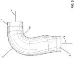
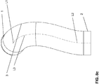
- the deflection bend shown in the figures serves to deflect a wastewater jet A in a downpipe system or in a downpipe delay. Wastewater A is fed to the deflection bend in the horizontal H and is then deflected into the vertical V by the deflection bend. The waste water A enters the deflection bend via the first pipe section 1, then passes the deflection section 3 and then the second pipe section 2, via which the waste water passes the deflection bend again leaves, forwarded.
- the deflection bend is designed in such a way that the water is set in rotation on the inner wall 15 of the deflection bend.
- the deflection bend comprises a first pipe section 1, a deflection section 3 and a second pipe section 2.
- the first pipe section 1 is directly and directly connected to the deflection section 3 and the deflection section 3 is immediately and directly connected to the second pipe section 2.
- the deflection section 3 thus connects the first pipeline section 1 to the second pipeline section 2.
- the first pipeline section 1 extends along a first guideline L1 designed as a straight line.
- the second pipeline section 2 extends along a second guideline L2, which is also designed as a straight line.
- the deflection section 3 extends along a third guideline L3, which third guideline L3 connects the first guideline L1 with the second guideline L2.
- the guidelines L1, L2, L3 mentioned herein or the sections L4, L5, L6 of the guideline L3 are to be understood as geometric guidelines, the first pipeline section 1, the deflection section 3 and the second pipeline section 2 being extruded geometrically along these guidelines. That is, the sections 1, 2, 3 extend along these guidelines in the sense of geometric extrusion.
- the first guideline L1 and the second guideline L2 span a vertical plane VE.
- the vertical plane VE is for example in the Figure 5a drawn. From a geometrical perspective, the vertical plane VE passes through the first guideline L1 and the second guideline L2.
- the first guideline L1 of the first pipe section 1 is at an angle of inclination ⁇ in the range from 90 ° to 100 ° to the second guideline L2 of the second pipe section 2.
- the second guideline L2 is essentially vertical and the first guideline L1 is depending on Angle ⁇ in the horizontal or inclined at an angle to the horizontal.
- An inclination plane NE is defined by the first guideline L1 and a reference axis R. stretched.
- the reference axis R intersects the first guideline L1 at right angles and is at right angles to the second guide line L2 and at right angles to the vertical plane VE.
- the deflection section 3 is formed from a plurality of subsections.
- the subsections in the figures bear the reference numerals 4, 5, 6.
- Each of the subsections 4, 5, 6 has a guideline section L4, L5, L6 assigned to the subsection 4, 5, 6.
- the guideline sections L4, L5, L6 are part of the third guideline L3, along which the deflecting section 3 extends.
- the third guideline L3 is accordingly defined by the guideline sections L4, L5, L6.
- At least one of the subsections 4, 5, 6 is designed in such a way that it allows the guideline L3 of the deflection section 3 to be deflected from the said vertical plane VE.
- the deflection is such that the wastewater A from the first pipe section 1 is set in rotation around the third guideline L3 as it flows through the said subsection 4, 5, 6 and can be fed to the second pipe section 2 in rotation.
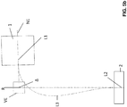
- the wastewater with the reference symbol A flows in the first pipe section 1 essentially as a horizontal stratified flow in the direction of the deflection section 3.
- a stratified flow is understood to mean that water and possibly solids flow in the lower area of the first pipeline section 1, while there is air in the upper area .
- the flow is represented by the flow lines AS.
- the wastewater A is led away from the vertical plane VE through at least one of the subsections 4, 5, 6.
- the wastewater A is thus deflected in such a way that a rotation about the guideline L3 of the deflection section 3 results.
- the wastewater A is set in rotation in the deflection section 3 and then also fed to the second pipeline section 2 in rotation.
- the deflection section 3 is designed in such a way that the waste water A flowing through the deflection section 3 experiences a rotation in a direction which is identical to the direction of the first deflection by the deflection section 3.
- the Figures 4a / 4b the wastewater is diverted to the left as seen in the direction of flow along the first guideline L1.
- the rotation then also takes place in the same direction, namely counterclockwise around the guidelines L3, L2.
- the "Left" direction is in the Figure 4a symbolized by the arrow on the left.
- the counterclockwise direction of rotation is represented by the reference symbol GUZ.
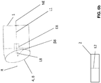
- This deflection is in the Figures 6a to 6d shown. The deflection is such that the end point of the guideline L4 of said subsection 4, starting from the inclination plane NE, comes to lie below the inclination plane NE in the direction of the second pipeline section 2.
- Said at least one section 4, 5, 6, which allows the guiding line L3 of the deflection section 3 to be deflected from the said vertical plane VE, is preferably a first section 4 in the form of a pipe bend 8.
- the pipe bend 8 extends along an arcuate guideline L4.
- the circular guideline L4 of the pipe bend 8 extends tangentially to the first guideline L1 of the first pipeline section 1. That is, the guideline L4 connects tangentially to the first guideline L1.
- the end area 1b of the first pipe section 1 and the starting area 8a of the said pipe bend 8 lie in a reference plane BE.
- the reference plane BE is a geometric reference plane. Depending on the design of the cross section of the deflecting section 3, only parts of the end region 1b or of the starting region 8a lie on the reference plane BE.
- the reference plane BE lies parallel to and at a distance from a first reference plane RE.
- the reference plane RE is spanned by the end face 1a of the first pipe section and is at right angles to the first guideline L1.
- the circular arc-shaped guideline L4 lies in a reference plane E8.
- the reference plane E8 is pivoted with respect to the inclination plane NE by a pivot angle ⁇ 8 of 10 ° to 70 °, here by 30 ° around the first guideline L1 to the second pipe section 2.
- the pipe bend 8 also has a bend angle ⁇ 8 of 10 ° to 80 °, here of 30 °.
- the bend angle ⁇ 8 is understood to mean that the pipe bend 8 and its guide line L4 extend over an opening angle.
- the first section 4 is followed by a second section 5.
- the geometric design of the second section 5 is explained in more detail.
- the second section 5 has the shape of a second pipe bend 9 which extends along a circular arc-shaped guideline L5.
- the arcuate guideline L5 of the second pipe bend 9 adjoins the arcuate guide line L4 of the first pipe bend 8 tangentially.
- the arcuate guideline L5 lies in one Reference plane E9. This means that the circular arc-shaped guideline L5 extends in the reference plane E9 or that the circular arc-shaped guideline L5 spans the reference plane E9.
- the reference plane E9 is with respect to the reference plane E8 of the first pipe bend 8 by a pivot angle ⁇ 9 of 10 ° to 80 °, in particular of 75 °, about a pivot axis S9 running in the said reference plane E8 and tangential to the circular arc-shaped guide line L8 of the first pipe bend 8 to the second Pipeline section 2 pivoted towards.
- Said reference plane R9 is spanned by the end region 8b of the first pipe bend 8.
- the circular arc-shaped guideline L8 of the first pipe bend 8 meets the reference plane R9 at right angles.
- the second pipe bend 9 also has a bend angle ⁇ 9 of 45 ° to 90 °, here of 72 °.
- the bend angle ⁇ 9 is understood to mean that the pipe bend 9 and its guide line L5 extend over an opening angle.
- the end region 9b of the second pipe bend 9 of the second subsection 5 lies in a plane E9 '.
- the plane E9 ' runs essentially at right angles to the vertical plane VE.
- the plane E9 ′ is preferably closer to the first pipe section 1 than to the second pipe section 2. This means that the two pipe bends 8, 9 lie in the first half of the total length of the guideline L3 through the deflection section.
- the second subsection is followed by a third subsection 6.
- the third subsection 6 provides a connection between the second subsection 5 and the second pipeline section 2.
- the third subsection 6 extends along a guideline L6.
- the guideline L6 is a polynomial train which tangentially connects to the guideline L5 of the second subsection 5 and which meets the guideline L2 of the second pipeline section 2 tangentially.
- the deflection section particularly preferably consists of the three named subsections. That is, between the first pipeline section and the second pipeline section, only the three subsections mentioned are present in the corresponding sequence.
- the cross section of the two pipeline sections 1, 2 is preferably circular with a constant diameter. This means that the two pipeline sections 1, 2 extend in a circular-cylindrical manner along the two guidelines L1, L2.
- the guidelines L1, L2 are the central axes of the two pipeline sections 1, 2.
- the cross section of the deflection section 3 can be designed in various ways.
- the cross section of the deflection section 3 is essentially constant circular and essentially corresponds to the cross section of the two pipeline sections 1, 2.
- the guideline L3 runs on the center line running centrally through the deflection section 3. This means that the guideline L3 extends through the geometric center points of the deflection section 3.
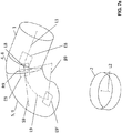
- the cross section of the deflection section 3 is enlarged in sections by an enlarged cross section 13.
- the cross-sectional enlargement 13 is such that the cross-sectional area of the deflection section 3 is enlarged with respect to the first and the second pipeline section 1, 2, respectively.
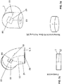
- This cross-sectional enlargement can be seen particularly well by the cross-sections Q1, Q2 and Q3 shown.
- the extension is such that, seen in cross section, a cross-sectional area with the original circular cross-section 14 and a cross-sectional area with the cross-sectional enlargement 13 are created.
- the guideline L3 extends through the geometric centers of the original circular cross-section 14.
- the cross-sectional enlargement 14 preferably increases the radius of the circular cross-section by 5% to 20% or by 10% to 20%.
- the enlarged cross-section extends to the side into which the section 4 of the deflection section 3 is deflected.
- the Figure 9a shows a cross section which lies on the reference plane R9. It can be clearly seen here that the guideline lies in the center of the original circular cross-section 14 and that the enlarged cross-section extends laterally outward.
- the Figure 9b shows the cross-section on the plane E9 'and the Figure 9c shows the cross-section on a plane normal to the guideline section L6 of the third subsection.
- the position of the guideline is also shown in these figures.
- REFERENCE LIST 1 first pipe section BE Reference plane 1a Face E8 Reference plane 1b End area E9 Reference plane 2 second pipe section R9 Reference plane 3 Deflection section S9 Swivel axis 4th first section E9 ' level 5 second section VE Vertical plane 6th third section NE Slope plane 8th first elbow HE Horizontal plane 8a Starting area A. sewage 8b End area GUZ Counter clockwise 9 second elbow AS Flow lines 9b End of the second pipe bend R.
- Reference axis 13 Cross-sectional enlargement ⁇ 8 Swivel angle between 14th circular cross-section Inclination level NE and 15th Inner wall Reference plane E8 L1 first guideline ⁇ 8 Elbow elbow 8 L2 second guideline L3 third guideline ⁇ 9 Swivel angle between reference plane E9 and reference plane E8 L4 Guideline section of the first subsection or of the pipe bend 8 ⁇ 9 Elbow elbow 9 L5 Guideline section of the second subsection ⁇ Angle between first guideline and second guideline L6 Guideline section of the third subsection H horizontal V vertical
Landscapes
- Engineering & Computer Science (AREA)
- Physics & Mathematics (AREA)
- General Engineering & Computer Science (AREA)
- Mechanical Engineering (AREA)
- Fluid Mechanics (AREA)
- Life Sciences & Earth Sciences (AREA)
- Public Health (AREA)
- Water Supply & Treatment (AREA)
- Hydrology & Water Resources (AREA)
- Health & Medical Sciences (AREA)
- Environmental & Geological Engineering (AREA)
- Structural Engineering (AREA)
- Rigid Pipes And Flexible Pipes (AREA)
- Sink And Installation For Waste Water (AREA)
- Branch Pipes, Bends, And The Like (AREA)
- Pipe Accessories (AREA)
- Undergarments, Swaddling Clothes, Handkerchiefs Or Underwear Materials (AREA)
Priority Applications (9)
| Application Number | Priority Date | Filing Date | Title |
|---|---|---|---|
| DK17154661.7T DK3358092T3 (da) | 2017-02-03 | 2017-02-03 | Afledningsbøjning |
| EP17154661.7A EP3358092B1 (de) | 2017-02-03 | 2017-02-03 | Umlenkbogen |
| RS20201359A RS61075B1 (sr) | 2017-02-03 | 2017-02-03 | Luk za preusmeravanje |
| CN201880009519.2A CN110234818B (zh) | 2017-02-03 | 2018-01-11 | 偏转弯头 |
| AU2018215123A AU2018215123B2 (en) | 2017-02-03 | 2018-01-11 | Deflecting bend |
| IL268410A IL268410B (en) | 2017-02-03 | 2018-01-11 | Deflecting bend |
| RU2019126382A RU2748804C2 (ru) | 2017-02-03 | 2018-01-11 | Отклоняющее колено |
| PCT/EP2018/050645 WO2018141525A1 (de) | 2017-02-03 | 2018-01-11 | Umlenkbogen |
| ZA2019/04856A ZA201904856B (en) | 2017-02-03 | 2019-07-24 | Deflecting bend |
Applications Claiming Priority (1)
| Application Number | Priority Date | Filing Date | Title |
|---|---|---|---|
| EP17154661.7A EP3358092B1 (de) | 2017-02-03 | 2017-02-03 | Umlenkbogen |
Publications (2)
| Publication Number | Publication Date |
|---|---|
| EP3358092A1 EP3358092A1 (de) | 2018-08-08 |
| EP3358092B1 true EP3358092B1 (de) | 2020-09-23 |
Family
ID=58094154
Family Applications (1)
| Application Number | Title | Priority Date | Filing Date |
|---|---|---|---|
| EP17154661.7A Active EP3358092B1 (de) | 2017-02-03 | 2017-02-03 | Umlenkbogen |
Country Status (9)
| Country | Link |
|---|---|
| EP (1) | EP3358092B1 (da) |
| CN (1) | CN110234818B (da) |
| AU (1) | AU2018215123B2 (da) |
| DK (1) | DK3358092T3 (da) |
| IL (1) | IL268410B (da) |
| RS (1) | RS61075B1 (da) |
| RU (1) | RU2748804C2 (da) |
| WO (1) | WO2018141525A1 (da) |
| ZA (1) | ZA201904856B (da) |
Families Citing this family (3)
| Publication number | Priority date | Publication date | Assignee | Title |
|---|---|---|---|---|
| CN114593303B (zh) * | 2020-12-07 | 2025-08-01 | 山西泫氏实业集团有限公司 | 一种用于排水立管水平偏置旋式衡压弯头 |
| DE102021113249B4 (de) * | 2021-05-21 | 2023-04-27 | Naber Holding Gmbh & Co. Kg | Rohrbogen für einen Abluftkanal einer Dunstabzugshaube |
| NL2036976B1 (en) * | 2024-02-06 | 2025-08-18 | Wavin Bv | A Deflecting Pipe Bend for Transporting a Multi-Phase Flow Medium |
Family Cites Families (9)
| Publication number | Priority date | Publication date | Assignee | Title |
|---|---|---|---|---|
| US1186280A (en) * | 1914-07-21 | 1916-06-06 | Harry Y Carson | Fitting for plumbing systems. |
| US1197395A (en) * | 1915-10-18 | 1916-09-05 | Louis E Politsky | Pipe-fitting. |
| US3346887A (en) * | 1965-02-11 | 1967-10-17 | Anaconda American Brass Co | Sanitary drain system, method, and fittings therefor |
| FR1572138A (da) * | 1967-02-08 | 1969-06-27 | ||
| DE2414130A1 (de) * | 1974-03-23 | 1975-10-09 | Tore Roesrud | Verbesserte abwasserrohrleitung |
| RU2457014C2 (ru) * | 2010-09-07 | 2012-07-27 | Федеральное государственное образовательное учреждение высшего профессионального образования "Кубанский государственный аграрный университет" | Устройство для изменения направления движения потоков жидкостей и газов |
| DE202011110778U1 (de) * | 2011-05-19 | 2016-05-11 | Geberit International Ag | Leitungszweigstück für Fallleitungen |
| CN202081475U (zh) * | 2011-05-27 | 2011-12-21 | 辽宁金禾实业有限公司 | 排水立管接头 |
| CN203346965U (zh) * | 2013-07-12 | 2013-12-18 | 徐水县兴华铸造有限公司 | 切入式管件及排水系统 |
-
2017
- 2017-02-03 EP EP17154661.7A patent/EP3358092B1/de active Active
- 2017-02-03 RS RS20201359A patent/RS61075B1/sr unknown
- 2017-02-03 DK DK17154661.7T patent/DK3358092T3/da active
-
2018
- 2018-01-11 IL IL268410A patent/IL268410B/en unknown
- 2018-01-11 WO PCT/EP2018/050645 patent/WO2018141525A1/de not_active Ceased
- 2018-01-11 RU RU2019126382A patent/RU2748804C2/ru active
- 2018-01-11 AU AU2018215123A patent/AU2018215123B2/en active Active
- 2018-01-11 CN CN201880009519.2A patent/CN110234818B/zh active Active
-
2019
- 2019-07-24 ZA ZA2019/04856A patent/ZA201904856B/en unknown
Non-Patent Citations (1)
| Title |
|---|
| None * |
Also Published As
| Publication number | Publication date |
|---|---|
| EP3358092A1 (de) | 2018-08-08 |
| ZA201904856B (en) | 2021-01-27 |
| CN110234818B (zh) | 2021-12-24 |
| IL268410A (en) | 2019-09-26 |
| DK3358092T3 (da) | 2020-12-21 |
| IL268410B (en) | 2022-07-01 |
| RU2748804C2 (ru) | 2021-05-31 |
| AU2018215123B2 (en) | 2022-11-24 |
| WO2018141525A1 (de) | 2018-08-09 |
| AU2018215123A1 (en) | 2019-07-18 |
| CN110234818A (zh) | 2019-09-13 |
| RS61075B1 (sr) | 2020-12-31 |
| RU2019126382A3 (da) | 2021-03-17 |
| RU2019126382A (ru) | 2021-03-03 |
Similar Documents
| Publication | Publication Date | Title |
|---|---|---|
| EP2281138B1 (de) | Strömungsoptimierter rohrbogen | |
| EP2525128B1 (de) | Übergangsstück | |
| EP3358092B1 (de) | Umlenkbogen | |
| WO2015185460A1 (de) | Umlenkbogen | |
| EP0898139A2 (de) | Wärmetauscher, insbesondere für eine Heiz- und Kühlanordnung eines Extruderrohres | |
| EP0121158B1 (de) | Kühlvorrichtung für aus einem Folienblaskopf extrudierte Kunststoffschlauchfolien | |
| DE3725389A1 (de) | Auslaufrohr | |
| DE102015009528B3 (de) | Stufenlos einstellbare Kalibrierhülse für extrudierte Kunststoffrohre | |
| EP1882786B1 (de) | Umlenkbogen für eine Falleitung | |
| DE102005028087B4 (de) | Vorrichtung zur Abdichtung eines Vakuumtankes | |
| DE102015003859A1 (de) | Ausbläser | |
| EP1091463B1 (de) | Kabelführungsrohr | |
| EP3304035B1 (de) | Messdüse zur bestimmung der dehnviskosität von polymerschmelzen | |
| EP2447424A1 (de) | Leitungszweigstück für Fallleitungen | |
| DE202011110778U1 (de) | Leitungszweigstück für Fallleitungen | |
| DE102006018374A1 (de) | Wellrohr aus thermoplastischem Kunststoff | |
| DE10306425B4 (de) | Einrichtung zur Abdichtung des Ein- oder Auslasses einer Behandlungsstrecke | |
| DE3614631C2 (da) | ||
| DE2913757C2 (de) | Verbindungsanordnung für die beiden Enden von zwei Rohren, insbesondere Kühlrohren einer Industrieofenwand | |
| EP0309820A2 (de) | Lüftungskanal-Versteifung | |
| EP2648884B1 (de) | Folienblaskopf | |
| WO2025012110A1 (de) | Umlenkrohrstück | |
| EP1499826B1 (de) | Rohrabzweigung für eine innen liegende zirkulation | |
| DE974109C (de) | UEberwachungseinrichtung fuer Dampfwasserableiter | |
| EP3366969A1 (de) | Rohranbohrarmatur |
Legal Events
| Date | Code | Title | Description |
|---|---|---|---|
| PUAI | Public reference made under article 153(3) epc to a published international application that has entered the european phase |
Free format text: ORIGINAL CODE: 0009012 |
|
| STAA | Information on the status of an ep patent application or granted ep patent |
Free format text: STATUS: THE APPLICATION HAS BEEN PUBLISHED |
|
| AK | Designated contracting states |
Kind code of ref document: A1 Designated state(s): AL AT BE BG CH CY CZ DE DK EE ES FI FR GB GR HR HU IE IS IT LI LT LU LV MC MK MT NL NO PL PT RO RS SE SI SK SM TR |
|
| AX | Request for extension of the european patent |
Extension state: BA ME |
|
| STAA | Information on the status of an ep patent application or granted ep patent |
Free format text: STATUS: REQUEST FOR EXAMINATION WAS MADE |
|
| 17P | Request for examination filed |
Effective date: 20190111 |
|
| RBV | Designated contracting states (corrected) |
Designated state(s): AL AT BE BG CH CY CZ DE DK EE ES FI FR GB GR HR HU IE IS IT LI LT LU LV MC MK MT NL NO PL PT RO RS SE SI SK SM TR |
|
| REG | Reference to a national code |
Ref country code: DE Ref legal event code: R079 Ref document number: 502017007358 Country of ref document: DE Free format text: PREVIOUS MAIN CLASS: E03C0001122000 Ipc: F15D0001040000 |
|
| GRAP | Despatch of communication of intention to grant a patent |
Free format text: ORIGINAL CODE: EPIDOSNIGR1 |
|
| STAA | Information on the status of an ep patent application or granted ep patent |
Free format text: STATUS: GRANT OF PATENT IS INTENDED |
|
| RIC1 | Information provided on ipc code assigned before grant |
Ipc: F15D 1/04 20060101AFI20191030BHEP Ipc: E03C 1/12 20060101ALI20191030BHEP Ipc: E03C 1/122 20060101ALI20191030BHEP |
|
| INTG | Intention to grant announced |
Effective date: 20191119 |
|
| GRAJ | Information related to disapproval of communication of intention to grant by the applicant or resumption of examination proceedings by the epo deleted |
Free format text: ORIGINAL CODE: EPIDOSDIGR1 |
|
| STAA | Information on the status of an ep patent application or granted ep patent |
Free format text: STATUS: REQUEST FOR EXAMINATION WAS MADE |
|
| INTC | Intention to grant announced (deleted) | ||
| GRAP | Despatch of communication of intention to grant a patent |
Free format text: ORIGINAL CODE: EPIDOSNIGR1 |
|
| STAA | Information on the status of an ep patent application or granted ep patent |
Free format text: STATUS: GRANT OF PATENT IS INTENDED |
|
| INTG | Intention to grant announced |
Effective date: 20200515 |
|
| GRAS | Grant fee paid |
Free format text: ORIGINAL CODE: EPIDOSNIGR3 |
|
| GRAA | (expected) grant |
Free format text: ORIGINAL CODE: 0009210 |
|
| STAA | Information on the status of an ep patent application or granted ep patent |
Free format text: STATUS: THE PATENT HAS BEEN GRANTED |
|
| AK | Designated contracting states |
Kind code of ref document: B1 Designated state(s): AL AT BE BG CH CY CZ DE DK EE ES FI FR GB GR HR HU IE IS IT LI LT LU LV MC MK MT NL NO PL PT RO RS SE SI SK SM TR |
|
| REG | Reference to a national code |
Ref country code: GB Ref legal event code: FG4D Free format text: NOT ENGLISH |
|
| REG | Reference to a national code |
Ref country code: CH Ref legal event code: EP |
|
| REG | Reference to a national code |
Ref country code: IE Ref legal event code: FG4D Free format text: LANGUAGE OF EP DOCUMENT: GERMAN |
|
| REG | Reference to a national code |
Ref country code: AT Ref legal event code: REF Ref document number: 1316653 Country of ref document: AT Kind code of ref document: T Effective date: 20201015 Ref country code: DE Ref legal event code: R096 Ref document number: 502017007358 Country of ref document: DE |
|
| REG | Reference to a national code |
Ref country code: CH Ref legal event code: NV Representative=s name: ISLER AND PEDRAZZINI AG, CH |
|
| REG | Reference to a national code |
Ref country code: NL Ref legal event code: FP |
|
| REG | Reference to a national code |
Ref country code: SE Ref legal event code: TRGR |
|
| REG | Reference to a national code |
Ref country code: FI Ref legal event code: FGE |
|
| REG | Reference to a national code |
Ref country code: DK Ref legal event code: T3 Effective date: 20201217 |
|
| PG25 | Lapsed in a contracting state [announced via postgrant information from national office to epo] |
Ref country code: BG Free format text: LAPSE BECAUSE OF FAILURE TO SUBMIT A TRANSLATION OF THE DESCRIPTION OR TO PAY THE FEE WITHIN THE PRESCRIBED TIME-LIMIT Effective date: 20201223 Ref country code: GR Free format text: LAPSE BECAUSE OF FAILURE TO SUBMIT A TRANSLATION OF THE DESCRIPTION OR TO PAY THE FEE WITHIN THE PRESCRIBED TIME-LIMIT Effective date: 20201224 Ref country code: HR Free format text: LAPSE BECAUSE OF FAILURE TO SUBMIT A TRANSLATION OF THE DESCRIPTION OR TO PAY THE FEE WITHIN THE PRESCRIBED TIME-LIMIT Effective date: 20200923 |
|
| REG | Reference to a national code |
Ref country code: NO Ref legal event code: T2 Effective date: 20200923 |
|
| PG25 | Lapsed in a contracting state [announced via postgrant information from national office to epo] |
Ref country code: LV Free format text: LAPSE BECAUSE OF FAILURE TO SUBMIT A TRANSLATION OF THE DESCRIPTION OR TO PAY THE FEE WITHIN THE PRESCRIBED TIME-LIMIT Effective date: 20200923 |
|
| REG | Reference to a national code |
Ref country code: LT Ref legal event code: MG4D |
|
| PG25 | Lapsed in a contracting state [announced via postgrant information from national office to epo] |
Ref country code: SM Free format text: LAPSE BECAUSE OF FAILURE TO SUBMIT A TRANSLATION OF THE DESCRIPTION OR TO PAY THE FEE WITHIN THE PRESCRIBED TIME-LIMIT Effective date: 20200923 Ref country code: CZ Free format text: LAPSE BECAUSE OF FAILURE TO SUBMIT A TRANSLATION OF THE DESCRIPTION OR TO PAY THE FEE WITHIN THE PRESCRIBED TIME-LIMIT Effective date: 20200923 Ref country code: PT Free format text: LAPSE BECAUSE OF FAILURE TO SUBMIT A TRANSLATION OF THE DESCRIPTION OR TO PAY THE FEE WITHIN THE PRESCRIBED TIME-LIMIT Effective date: 20210125 Ref country code: RO Free format text: LAPSE BECAUSE OF FAILURE TO SUBMIT A TRANSLATION OF THE DESCRIPTION OR TO PAY THE FEE WITHIN THE PRESCRIBED TIME-LIMIT Effective date: 20200923 Ref country code: LT Free format text: LAPSE BECAUSE OF FAILURE TO SUBMIT A TRANSLATION OF THE DESCRIPTION OR TO PAY THE FEE WITHIN THE PRESCRIBED TIME-LIMIT Effective date: 20200923 Ref country code: EE Free format text: LAPSE BECAUSE OF FAILURE TO SUBMIT A TRANSLATION OF THE DESCRIPTION OR TO PAY THE FEE WITHIN THE PRESCRIBED TIME-LIMIT Effective date: 20200923 |
|
| PG25 | Lapsed in a contracting state [announced via postgrant information from national office to epo] |
Ref country code: PL Free format text: LAPSE BECAUSE OF FAILURE TO SUBMIT A TRANSLATION OF THE DESCRIPTION OR TO PAY THE FEE WITHIN THE PRESCRIBED TIME-LIMIT Effective date: 20200923 Ref country code: IS Free format text: LAPSE BECAUSE OF FAILURE TO SUBMIT A TRANSLATION OF THE DESCRIPTION OR TO PAY THE FEE WITHIN THE PRESCRIBED TIME-LIMIT Effective date: 20210123 Ref country code: AL Free format text: LAPSE BECAUSE OF FAILURE TO SUBMIT A TRANSLATION OF THE DESCRIPTION OR TO PAY THE FEE WITHIN THE PRESCRIBED TIME-LIMIT Effective date: 20200923 Ref country code: ES Free format text: LAPSE BECAUSE OF FAILURE TO SUBMIT A TRANSLATION OF THE DESCRIPTION OR TO PAY THE FEE WITHIN THE PRESCRIBED TIME-LIMIT Effective date: 20200923 |
|
| REG | Reference to a national code |
Ref country code: DE Ref legal event code: R097 Ref document number: 502017007358 Country of ref document: DE |
|
| PG25 | Lapsed in a contracting state [announced via postgrant information from national office to epo] |
Ref country code: SK Free format text: LAPSE BECAUSE OF FAILURE TO SUBMIT A TRANSLATION OF THE DESCRIPTION OR TO PAY THE FEE WITHIN THE PRESCRIBED TIME-LIMIT Effective date: 20200923 |
|
| PLBE | No opposition filed within time limit |
Free format text: ORIGINAL CODE: 0009261 |
|
| STAA | Information on the status of an ep patent application or granted ep patent |
Free format text: STATUS: NO OPPOSITION FILED WITHIN TIME LIMIT |
|
| PG25 | Lapsed in a contracting state [announced via postgrant information from national office to epo] |
Ref country code: SI Free format text: LAPSE BECAUSE OF FAILURE TO SUBMIT A TRANSLATION OF THE DESCRIPTION OR TO PAY THE FEE WITHIN THE PRESCRIBED TIME-LIMIT Effective date: 20200923 |
|
| 26N | No opposition filed |
Effective date: 20210624 |
|
| PG25 | Lapsed in a contracting state [announced via postgrant information from national office to epo] |
Ref country code: MC Free format text: LAPSE BECAUSE OF FAILURE TO SUBMIT A TRANSLATION OF THE DESCRIPTION OR TO PAY THE FEE WITHIN THE PRESCRIBED TIME-LIMIT Effective date: 20200923 |
|
| PG25 | Lapsed in a contracting state [announced via postgrant information from national office to epo] |
Ref country code: LU Free format text: LAPSE BECAUSE OF NON-PAYMENT OF DUE FEES Effective date: 20210203 |
|
| PG25 | Lapsed in a contracting state [announced via postgrant information from national office to epo] |
Ref country code: IE Free format text: LAPSE BECAUSE OF NON-PAYMENT OF DUE FEES Effective date: 20210203 Ref country code: FR Free format text: LAPSE BECAUSE OF NON-PAYMENT OF DUE FEES Effective date: 20210228 |
|
| P01 | Opt-out of the competence of the unified patent court (upc) registered |
Effective date: 20230516 |
|
| PG25 | Lapsed in a contracting state [announced via postgrant information from national office to epo] |
Ref country code: CY Free format text: LAPSE BECAUSE OF FAILURE TO SUBMIT A TRANSLATION OF THE DESCRIPTION OR TO PAY THE FEE WITHIN THE PRESCRIBED TIME-LIMIT Effective date: 20200923 |
|
| PG25 | Lapsed in a contracting state [announced via postgrant information from national office to epo] |
Ref country code: HU Free format text: LAPSE BECAUSE OF FAILURE TO SUBMIT A TRANSLATION OF THE DESCRIPTION OR TO PAY THE FEE WITHIN THE PRESCRIBED TIME-LIMIT; INVALID AB INITIO Effective date: 20170203 |
|
| PG25 | Lapsed in a contracting state [announced via postgrant information from national office to epo] |
Ref country code: MK Free format text: LAPSE BECAUSE OF FAILURE TO SUBMIT A TRANSLATION OF THE DESCRIPTION OR TO PAY THE FEE WITHIN THE PRESCRIBED TIME-LIMIT Effective date: 20200923 |
|
| REG | Reference to a national code |
Ref country code: NL Ref legal event code: PD Owner name: GEBERIT HOLDING AG; CH Free format text: DETAILS ASSIGNMENT: CHANGE OF OWNER(S), MERGE; FORMER OWNER NAME: GEBERIT INTERNATIONAL AG Effective date: 20240604 Ref country code: NL Ref legal event code: HC Owner name: GEBERIT INTERNATIONAL AG; CH Free format text: DETAILS ASSIGNMENT: CHANGE OF OWNER(S), CHANGE OF OWNER(S) NAME; FORMER OWNER NAME: GEBERIT HOLDING AG Effective date: 20240604 |
|
| REG | Reference to a national code |
Ref country code: BE Ref legal event code: PD Owner name: GEBERIT HOLDING AG; CH Free format text: DETAILS ASSIGNMENT: CHANGE OF OWNER(S), MERGE; FORMER OWNER NAME: GEBERIT INTERNATIONAL AG Effective date: 20240528 Ref country code: BE Ref legal event code: HC Owner name: GEBERIT INTERNATIONAL AG; CH Free format text: DETAILS ASSIGNMENT: CHANGE OF OWNER(S), CHANGE OF OWNER(S) NAME; FORMER OWNER NAME: GEBERIT HOLDING AG Effective date: 20240528 |
|
| PG25 | Lapsed in a contracting state [announced via postgrant information from national office to epo] |
Ref country code: MT Free format text: LAPSE BECAUSE OF FAILURE TO SUBMIT A TRANSLATION OF THE DESCRIPTION OR TO PAY THE FEE WITHIN THE PRESCRIBED TIME-LIMIT Effective date: 20200923 |
|
| REG | Reference to a national code |
Ref country code: AT Ref legal event code: PC Ref document number: 1316653 Country of ref document: AT Kind code of ref document: T Owner name: GEBERIT INTERNATIONAL AG, CH Effective date: 20241118 |
|
| REG | Reference to a national code |
Ref country code: CH Ref legal event code: U11 Free format text: ST27 STATUS EVENT CODE: U-0-0-U10-U11 (AS PROVIDED BY THE NATIONAL OFFICE) Effective date: 20260301 |
|
| PGFP | Annual fee paid to national office [announced via postgrant information from national office to epo] |
Ref country code: NL Payment date: 20260218 Year of fee payment: 10 |
|
| PGFP | Annual fee paid to national office [announced via postgrant information from national office to epo] |
Ref country code: SE Payment date: 20260218 Year of fee payment: 10 |
|
| PGFP | Annual fee paid to national office [announced via postgrant information from national office to epo] |
Ref country code: GB Payment date: 20260219 Year of fee payment: 10 |
|
| PGFP | Annual fee paid to national office [announced via postgrant information from national office to epo] |
Ref country code: DE Payment date: 20260218 Year of fee payment: 10 Ref country code: NO Payment date: 20260220 Year of fee payment: 10 Ref country code: DK Payment date: 20260220 Year of fee payment: 10 |
|
| PGFP | Annual fee paid to national office [announced via postgrant information from national office to epo] |
Ref country code: AT Payment date: 20260219 Year of fee payment: 10 |
|
| PGFP | Annual fee paid to national office [announced via postgrant information from national office to epo] |
Ref country code: BE Payment date: 20260218 Year of fee payment: 10 Ref country code: FI Payment date: 20260226 Year of fee payment: 10 Ref country code: IT Payment date: 20260219 Year of fee payment: 10 |
|
| PGFP | Annual fee paid to national office [announced via postgrant information from national office to epo] |
Ref country code: RS Payment date: 20260123 Year of fee payment: 10 |
|
| PGFP | Annual fee paid to national office [announced via postgrant information from national office to epo] |
Ref country code: TR Payment date: 20260128 Year of fee payment: 10 |
|
| PGFP | Annual fee paid to national office [announced via postgrant information from national office to epo] |
Ref country code: CH Payment date: 20260301 Year of fee payment: 10 |