EP3358087B2 - Arbeitsgerät, insbesondere für baustelle, und steuerverfahren eines solchen geräts - Google Patents
Arbeitsgerät, insbesondere für baustelle, und steuerverfahren eines solchen geräts Download PDFInfo
- Publication number
- EP3358087B2 EP3358087B2 EP18152866.2A EP18152866A EP3358087B2 EP 3358087 B2 EP3358087 B2 EP 3358087B2 EP 18152866 A EP18152866 A EP 18152866A EP 3358087 B2 EP3358087 B2 EP 3358087B2
- Authority
- EP
- European Patent Office
- Prior art keywords
- arm
- bucket
- control
- holder
- vehicle
- Prior art date
- Legal status (The legal status is an assumption and is not a legal conclusion. Google has not performed a legal analysis and makes no representation as to the accuracy of the status listed.)
- Active
Links
Images

Classifications
-
- E—FIXED CONSTRUCTIONS
- E02—HYDRAULIC ENGINEERING; FOUNDATIONS; SOIL SHIFTING
- E02F—DREDGING; SOIL-SHIFTING
- E02F3/00—Dredgers; Soil-shifting machines
- E02F3/04—Dredgers; Soil-shifting machines mechanically-driven
- E02F3/28—Dredgers; Soil-shifting machines mechanically-driven with digging tools mounted on a dipper- or bucket-arm, i.e. there is either one arm or a pair of arms, e.g. dippers, buckets
- E02F3/283—Dredgers; Soil-shifting machines mechanically-driven with digging tools mounted on a dipper- or bucket-arm, i.e. there is either one arm or a pair of arms, e.g. dippers, buckets with a single arm pivoted directly on the chassis
- E02F3/286—Dredgers; Soil-shifting machines mechanically-driven with digging tools mounted on a dipper- or bucket-arm, i.e. there is either one arm or a pair of arms, e.g. dippers, buckets with a single arm pivoted directly on the chassis telescopic or slidable
-
- E—FIXED CONSTRUCTIONS
- E02—HYDRAULIC ENGINEERING; FOUNDATIONS; SOIL SHIFTING
- E02F—DREDGING; SOIL-SHIFTING
- E02F9/00—Component parts of dredgers or soil-shifting machines, not restricted to one of the kinds covered by groups E02F3/00 - E02F7/00
- E02F9/20—Drives; Control devices
- E02F9/2004—Control mechanisms, e.g. control levers
- E02F9/2012—Setting the functions of the control levers, e.g. changing assigned functions among operations levers, setting functions dependent on the operator or seat orientation
Definitions
- the invention relates to a work machine, in particular a construction site machine, as well as a method for controlling such a machine.
- Such a work machine is known as illustrated in the patent EP 2.805.910 .
- the driver of the machine controls the elevation of the bucket-carrying arm to bring the base of the bucket into a position in which it extends parallel to the plane of the bottom of the skip and above the skip.
- the bucket holder is then driven in a pivoting movement towards the dumping position.
- the driver of the machine actuates the bucket holder movement drive control member generally formed by a joystick.
- this pivoting movement there is a risk that the bucket will hit the wall of the skip and damage it if the bucket has not been sufficiently moved away from the top of the skip.
- An aim of the invention is to propose a work machine and a method for controlling said machine, the designs of which make it possible to reduce the risks of damage to a skip during operations of dumping material into the skip.
- the invention relates to a work machine according to claim 1.
- control unit is configured to, in the second operating mode, control the second and third actuators as a function at least of the data provided by the first control member to allow, in the requested state of said first control member, in parallel with a pivoting movement of the bucket holder, a relative movement of the arm sections.
- the control unit is therefore configured to, in the second operating mode, control in parallel the second and third actuators from the first control member forming a control member common to the first and second actuators to allow, in the coupled state of the bucket to the bucket holder, a rotation of the bucket, in particular of the leading edge of the bucket around a substantially constant instantaneous center of rotation.
- control unit is configured to, in the second operating mode, in the requested state of said first control member corresponding to the positioned state of said first control member in said first control zone, control at least the second and third actuators from and as a function of the data provided by said first control member forming a control member common to the second and third actuators.
- this design allows, in the coupled state of the bucket to the bucket holder, a rotation of the bucket and, in particular, of the leading edge of the bucket, around a substantially constant instantaneous center of rotation.
- the machine comprises an interface for inputting or selecting data relating to the size of the bucket and the control unit is configured to, in the second operating mode, control at least the second and third actuators as a function at least of the data provided by said first control member and of the size of the bucket.
- the size of the bucket makes it possible, within the framework of a possibility of mounting buckets of different sizes on the machine, to guarantee again, in the coupled state of the bucket to the bucket holder, a rotation of the bucket and, in particular, of the leading edge of the bucket, around a substantially constant instantaneous center of rotation.
- the machine comprises at least one sensor for measuring a parameter representative of the angular position of the bucket holder relative to the arm, and the control unit is configured to, in the second operating mode, control the second and third actuators as a function at least of the data provided by said first control member and of the angular position of the bucket holder.
- the or at least one of the sensors for measuring a parameter representative of the angular position of the bucket holder relative to the arm is a sensor for measuring the angle formed between the bucket holder and the arm or a sensor for measuring the stroke of the third actuator.
- control unit is configured to, in the second operating mode, control the first, second and third actuators as a function at least of the data provided by said first control member, in the positioned state of said first control member in said first control zone.
- control unit is configured to, in the second operating mode, control the first, second and third actuators at least from and as a function of the data provided by the first control member, this first control member forming a member common to the first, second and third actuators to allow, in parallel with a pivoting movement of the bucket holder, a relative movement of the arm sections and a rising and lowering movement of the arm.
- the machine comprises at least one sensor for measuring a parameter representative of the angular position of the arm. relative to the chassis, and the control unit is configured to, in the second operating mode, control the first, second and third actuators as a function at least of the data provided by said first control member and of the angular position of the arm.
- the or at least one of the sensors for measuring a parameter representative of the angular position of the arm relative to the chassis is a sensor for measuring the angle formed between the arm and the ground support plane of the chassis or a sensor for measuring the stroke of the first actuator.
- the machine comprises at least one sensor for measuring a parameter representative of the length of the arm
- the control unit is configured to, in the second operating mode, control at least the second and third actuators as a function at least of the data provided by said first control member and of the length of the arm.
- the first and second operating modes of the machine can be selectively activated by means of an activation member such as a button that can be actuated by the driver of the machine.
- the invention also relates to a method for controlling a work machine, in particular a construction site machine of the aforementioned type, the bucket holder of said machine being coupled to a bucket, characterized in that said method comprises, in the activated state of the second operating mode of the machine, by actuation by the driver of the machine of the first control member, a step of driving the arm sections in relative movement, preferably in the direction of an extension of the arm and of driving the bucket holder in pivoting movement towards the dumping position.
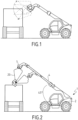
- the invention relates to a work machine 1, in particular a construction site machine, such as a hydraulic mechanical shovel, also called an excavator machine or bucket machine as shown.
- This machine 1 comprises a rolling chassis 2 equipped with a machine control cabin and a powertrain group 3 for driving the machine while moving on the ground.
- the powertrain group 3 comprises a heat engine, itself associated with a hydraulic pump capable of supplying fluid to a plurality of actuators which will be described below.
- the machine 1 also includes an arm 4 carried by the chassis 2.
- This arm 4 is a pivoting arm pivotally mounted about a so-called horizontal axis, orthogonal to the longitudinal axis of the arm 4, and parallel to the ground support plane of the machine 1, in the configuration of use of the machine 1 for the passage of the arm 4 from a low position to a high position and vice versa, using an actuator, such as a jack, called first actuator 5 and arranged between the arm 4 and the rolling chassis 2.
- an actuator such as a jack, called first actuator 5 and arranged between the arm 4 and the rolling chassis 2.
- a single double-acting jack is shown, supplied with fluid by the hydraulic pump.
- a pair of parallel single-acting jacks supplied in turn with fluid could have been used in an equivalent manner.
- This arm 4 is a telescopic arm formed, in the example shown, of two arm sections 41, 42 mounted with sliding interlocking, and driven in relative movement by an actuator, called second actuator 6, for the passage of the arm from a retracted position to an extended position and vice versa.
- This second actuator 6 is formed by a hydraulic cylinder whose body is mounted integrally with one arm section and the rod, with the other arm section.
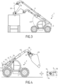
- the arm 4 is equipped at its free end with a bucket holder 7 itself intended to carry a bucket 20.
- This bucket holder 7 is mounted by means of an actuator, called third actuator 8, pivotable about a so-called horizontal axis, orthogonal to the longitudinal axis of the arm 4 between a digging position and a dumping position.
- the dumping position corresponds to the extreme position of pivoting towards the ground of the bucket holder 7, while the digging position corresponds to a position of pivoting towards the top of the bucket holder 7 and the associated bucket 20.
- the third actuator 8 is arranged between the bucket holder 7 and the arm 4 and can again consist of a double-acting hydraulic cylinder or a pair of single-acting cylinders.
- the pivoting movement drive of the bucket holder takes place about an axis parallel to the pivot axis of the arm.
- the machine 1 also comprises, arranged inside the driver's cabin, a first member 9 for controlling the movement of the arm 4 and the bucket holder 7, which can be actuated by the driver of the machine, and a second member 10 for controlling the movement of the arm 4 between a retracted position and an extended position, which can be actuated by the driver of the machine.
- the machine 1 also comprises a control unit 11 configured to control the first, second and third actuators according to the data provided by the control members 9 and 10.
- the fluid supply of the actuators using the hydraulic pump is controlled according to the control signals provided by the control unit 11.
- These control signals are themselves a function of the input data received by the control unit 11.
- the control unit comprises for example a microcontroller or a microprocessor associated with a memory.
- control signals provided by the control unit 11 generally act on members, such as distributors or valves, arranged on the connection between the pump and the actuator, to allow an appropriate supply of fluid to the actuators, in a manner known per se.
- the first control member 9 is a control lever also called a joystick.
- This first control member 9 is equipped at its base with two encoders to allow the transmission of two position signals of said first control member to the control unit 11, in a manner known per se.
- An example of such a control member is for example described in the patent FR 2 858 861 .
- This first control member 9 can thus be moved forward, backward, to the left, or to the right of the machine.
- the movements, towards the front and rear of the machine, of the first control member 9 control the upward and downward movement of the arm 4, while the movements, towards the left and to the right of the machine, of the first control member 9 control the pivoting movement of the bucket holder, as illustrated in the figures where the figure 4 illustrates a movement to the right of the first control member 9 and the positioning of the bucket holder in the dumping position.
- These forward/rearward and left/right directions correspond to the main directions, and the first control member can be driven in an infinite number of directions, the movement of the first control member in any direction corresponding to a combined action, proportional to the position of the first control member relative to the main directions.
- this first control member 9 is returned by a spring to the neutral position, i.e. in an intermediate position between right/left and front/rear, in the unstressed state.
- the position information sent to the control unit is therefore generally information relating to the angular position of the first control member, relative to the position it occupies in the neutral position.
- the first control member In this neutral position, when the first control member is moved angularly to the right within a predetermined angular sector, it controls the pivoting movement of the bucket holder in the direction of dumping of the bucket holder and the associated bucket.
- This first angular sector is called the first control zone 13.
- the first control member When the first control member is, from the neutral position, moved angularly to the left within a predetermined angular sector, it controls the pivoting movement of the bucket holder in the direction of digging of the bucket holder and the associated bucket.
- the second control member 10 is formed by a wheel positioned on the first control member 9. Actuation of this wheel allows the arm to be moved between a retracted position and an extended position. In fact, rotation of the wheel carried by the first control member 9 in one direction allows the arm to be extended by sliding movement, in the direction of extension of the arm, of the second arm section, and rotation of the wheel carried by the first control member 9 in an opposite direction allows the arm to be retracted.
- the control unit 11 controls the supply of hydraulic fluid to the first, second and third actuators as a function of the position data. provided by the first and second control members.
- the first, second and third actuators are each arranged on a hydraulic circuit equipped with at least one valve or distributor controllable by the control unit 1.
- This control unit 11 is here produced in the form of a controller or microprocessor in which computer instruction sets have been implemented to perform the functions of the control unit.
- the functions of the control unit 11 can be performed by dedicated electronic components or FPGA or ASIC type components. It is also possible to combine computer parts and electronic parts.
- Computer programs or computer instructions may be contained in program storage devices, such as computer-readable digital data storage media or executable programs. Programs or instructions may also be executed from program storage devices.
- a control unit 11 is configured to receive the position signals addressed to it by the first and second control members and to emit output signals to the valves or distributors equipping the hydraulic circuits of the first, second and third actuators, generally via solenoids equipping said valves or distributors.
- the first, second and third actuators control, depending on their hydraulic flow supply, a movement of the arm for the first and second actuators, or a movement of the bucket holder for the third actuator.
- the machine 1 comprises two selectively activatable operating modes.
- these two operating modes are selectively activatable by means of an activation member 12 formed here by a button actuated by the driver of the machine.
- This button is arranged in the cabin of the machine, at the dashboard.
- the machine is in the first operating mode.
- the first control member 9 sends signals to the control unit 11.
- This control unit 11 is configured to, from the signals received from the first control member, as a function of said signals, act on the power supply circuit of the first and/or third actuator, and thus control the lifting or lowering of the arm and/or the pivoting movement of the bucket holder in one direction or the other, as a function of the position signals sent by the first control member to the control unit 11.
- the second control member 10 formed by the wheel arranged on the joystick sends signals to the control unit 11.
- the control unit 11 is configured to, from the signals received from the second control member 10, act on the power supply circuit of the second actuator and thus control the retraction or extension of the arm.
- the first control member 9 When the second operating mode is activated, for example by pressing the button 12 by the driver of the machine, in the state requested by the driver of the machine, that is to say in the state driven in movement out of its neutral position, the first control member 9 sends signals to the control unit 11.
- This control unit 11 is configured to, from the signals received from the first control member, as a function of said signals, act on the supply circuit at least of the second and third actuators, to thus allow, in parallel, a pivoting movement of the bucket holder and a variation in the length of the arm.
- the control unit 11 is configured to, in the second operating mode, in the requested state of the first control member 9 corresponding to the positioned state of the first control member in the first control zone 13, control at least the second and third actuators, as a function of the data provided by the first control member 9.
- the control unit 11 is, in these circumstances, configured to control the second actuator 6 in the direction of an extension of the arm 4 and the third actuator 8 in the direction of a pivoting movement of the bucket holder 7 towards the dumping position.
- the extension length of the arm 4 and the pivot angle of the bucket holder 7 for a given position of the first control member 9 within the first control zone 13 are defined in correspondence.
- the machine 1 comprises an interface 14 for inputting or selecting data relating to the dimension of the bucket 20, and the control unit 11 is configured to, in the second operating mode, control the second and third actuators according to the data provided by said first control member 9 and the dimension of the bucket 20.
- the above formula is applied with L, a function of the dimension selected or entered by the driver of the machine.
- This interface can comprise a simple touch screen on which the different dimensions of the bucket can be displayed, the driver of the machine selecting the dimension corresponding to the bucket equipping the machine.
- the machine 1 comprises a sensor 15 for measuring a parameter representative of the angular position of the bucket holder 7 relative to the arm 4, and the control unit is configured to, in the second operating mode, control the second and third actuators as a function of the data provided by the first control member 9 and the angular position of the bucket holder.
- This sensor 15 for measuring a parameter representative of the angular position of the bucket holder 7 relative to the arm 4 may be a sensor for measuring the angle formed between the bucket holder 7 and the arm 4, or a sensor for measuring the stroke of the third actuator 8.
- the hydraulic flow rate inside the hydraulic supply circuits of the second and third actuators can vary in an undesirable manner, because the hydraulic source of the machine is requested by other parts of the machine such as the brakes, the steering, the fan or others.
- the presence of a sensor makes it possible to avoid a drift in the movements between extension of the arm and pivoting movement of the bucket holder.
- control unit 11 can be configured to, in the second operating mode, control in synchronism and in parallel not only the second and third actuators, but also the first actuator, depending on the data provided by the first control member in the positioned state of the first control member in the first control zone 13.
- control unit 11 in the second operating mode, in the positioned state of the first control member 9 in said first control zone 13, the control unit 11 is configured to control the first actuator in the direction of lifting the arm, the second actuator in the direction of extending the arm and the third actuator in the direction of pivoting movement of the bucket holder towards the dumping position, the extension length of the arm and the pivot angles of the arm and the bucket holder being, for a given position of the first control member 9 within the first control zone 13, defined correspondingly.
- the objective is always to obtain, at the level of the leading edge of the bucket, a rotation of the latter around a quasi-constant instantaneous center of rotation.
- the machine comprises a sensor 16 for measuring a parameter representative of the angular position of the arm 4 relative to the chassis 2, and the control unit 11 is configured to, in the second operating mode, control the first, second and third actuators according to the data provided by the first control member 9 and the angular position of the arm.
- This sensor 16 for measuring a parameter representative of the angular position of the arm relative to the chassis may be a sensor for measuring the angle formed between the arm and the ground support plane of the chassis, or a sensor for measuring the stroke of the first actuator 5. Additional sensors may be provided to refine the settings and control the movements in synchronism, according to the data provided by said sensors.
- the machine can also comprise a sensor 17 for measuring a parameter representative of the length of the arm 4, and the control unit 11 can be configured to, in the second operating mode, control the second and third actuators as a function of the data provided by the first control member 9 and the length of the arm 4.
Landscapes
- Engineering & Computer Science (AREA)
- Mining & Mineral Resources (AREA)
- Civil Engineering (AREA)
- General Engineering & Computer Science (AREA)
- Structural Engineering (AREA)
- Mechanical Engineering (AREA)
- Operation Control Of Excavators (AREA)
Claims (10)
- Arbeitsgerät (1), insbesondere für Baustelle, umfassend:ein Fahrgestell (2), das mit einem Motorantriebsaggregat ausgestattet ist,einen Arm (4), der von dem Fahrgestell (2) getragen wird und mittels einer ersten Betätigungsvorrichtung (5) montiert ist, die zwischen einer oberen und einer unteren Position schwenkbeweglich ist, wobei der Arm (4), der aus mindestens zwei Armabschnitten (41, 42) gebildet ist, ein teleskopischer Arm mit einer Länge ist, die zwischen einer eingefahrenen Position und einer ausgezogenen Position des Arms (4) mit Hilfe einer Betätigungsvorrichtung zur relativen Bewegung der Armabschnitte, genannt zweite Betätigungsvorrichtung (6), eingestellt werden kann,einen Schaufelarm (7), der an dem freien Ende des Arms (4) angeordnet ist, eine Schaufel (20), die dazu bestimmt ist, von dem Schaufelarm (7) getragen zu werden, wobei der Schaufelarm (7), der an der Schaufel (20) koppelbar ist, mittels einer Betätigungsvorrichtung, bezeichnet als dritte Betätigungsvorrichtung (8), schwenkbeweglich um eine orthogonale Achse zu der Längsachse des Arms (4) zwischen einer Aushubposition und einer Entleerungsposition montiert ist, wobei die Entleerungsposition der Endposition des Schwenkens hin zum Boden des Schaufelarms (7) entspricht, ein erstes Organ (9), wie z. B. ein Joystick, zum Steuern des Bewegungsantriebs des Arms (4) und des Schaufelarms (7), das von dem Fahrer der Maschine betätigt werden kann,ein zweites Steuerorgan (10) für den Bewegungsantrieb des Arms (4) zwischen einer eingezogenen Position und einer ausgezogenen Position, das von dem Fahrer des Geräts betätigt werden kann,eine Führungseinheit (11), die konfiguriert ist, um die erste (5), die zweite (6) und die dritte (8) Betätigungsvorrichtung abhängig von den Daten zu steuern, die von den Steuerorganen (9, 10) bereitgestellt werden,das Gerät (1) umfassend mindestens einen ersten und einen zweiten selektiv aktivierbaren Betriebsmodus,wobei die Führungseinheit (11) konfiguriert ist, um in dem ersten Betriebsmodus die dritte Betätigungsvorrichtung (8) abhängig von mindestens den Daten, die von dem ersten Steuerorgan (9) bereitgestellt werden, und die zweite Betätigungsvorrichtung (6) abhängig von mindestens den Daten, die von dem zweiten Steuerorgan (10) bereitgestellt werden, zu steuern, dadurch gekennzeichnet, dass das erste Steuerorgan (9), das von dem Fahrer des Geräts betätigt werden kann, beweglich zwischen einer neutralen Position und einem Steuerbereich zur schwenkenden Bewegung (7) im Sinne einer Entleerung montiert ist und als erster Steuerbereich (13) bezeichnet wird,dass die Führungseinheit (11) konfiguriert ist, um in dem zweiten Betriebsmodus bei dem angeforderten Zustand des ersten Steuerorgans (9), der dem positionierten Zustand des ersten Steuerorgans (9) in dem ersten Steuerbereich (13) entspricht, die zweite (6) und die dritte (8) Betätigungsvorrichtung abhängig von zumindest den Daten zu steuern, die von dem ersten Steuerorgan (9) bereitgestellt werden, wobei die Führungseinheit (11) konfiguriert ist, um in diesem zweiten Betriebsmodus bei dem positionierten Zustand des ersten Steuerorgans (9) in dem ersten Steuerbereich (13), die zweite Betätigungsvorrichtung (6) in Richtung einer Verlängerung des Arms (4) und die dritte Betätigungsvorrichtung (8) in Richtung einer Schwenkbewegung des Schaufelarms (7) in Richtung der Entleerungsposition zu steuern, wobei die Länge der Verlängerung des Arms (4) und der Schwenkwinkel des Schaufelarms (7) für eine gegebene Position des ersten Steuerorgans (9) im Inneren des ersten Steuerbereichs (13) entsprechend definiert sind, um eine Schwenkbewegung des Schaufelarms (7) und der assoziierten Schaufel (20) um ein nahezu konstantes momentanes Drehzentrum zu gewährleisten, das auf der Höhe der Vorderkante der Schaufel (20) angeordnet ist.
- Arbeitsgerät (1) nach dem vorhergehenden Anspruch,
dadurch gekennzeichnet, dass das Gerät (1) eine Schnittstelle (14) zu dem Eingang oder zu der Auswahl von Daten mit Bezug auf die Abmessung der Schaufel (20) umfasst, und dadurch, dass die Führungseinheit (11) konfiguriert ist, um in dem zweiten Betriebsmodus mindestens die zweite (6) und dritte (8) Betätigungsvorrichtung je nach mindestens den Daten zu steuern, die von dem ersten Steuerorgan (9) und der Abmessung der Schaufel (20) bereitgestellt werden. - Arbeitsgerät (1) nach einem der vorhergehenden Ansprüche,
dadurch gekennzeichnet, dass das Gerät (1) mindestens einen Sensor (15) zum Messen eines Parameters umfasst, der repräsentativ für die Winkelposition des Schaufelarms (7) in Bezug auf den Arm (4) ist, und dadurch, dass die Führungseinheit (11) konfiguriert ist, um in dem zweiten Betriebsmodus die zweite (6) und dritte (8) Betätigungsvorrichtung je nach mindestens den Daten zu steuern, die von dem ersten Steuerorgan (9) und der Winkelposition des Schaufelarms (7) bereitgestellt werden. - Arbeitsgerät (1) nach dem vorhergehenden Anspruch,
dadurch gekennzeichnet, dass der oder mindestens einer der Sensoren (15) zum Messen eines Parameters, der repräsentativ für die Winkelposition des Schaufelarms (7) in Bezug auf den Arm (4) ist, ein Sensor zum Messen des Winkels, der zwischen dem Schaufelarm (7) und dem Arm (4) gebildet ist, oder ein Sensor zum Messen des Wegs der dritten Betätigungsvorrichtung (8) ist. - Arbeitsgerät (1) nach einem der vorhergehenden Ansprüche,
dadurch gekennzeichnet, dass die Führungseinheit (11) konfiguriert ist, um in dem zweiten Betriebsmodus die erste (5), die zweite (6) und die dritte (8) Betätigungsvorrichtung je nach mindestens den Daten, die von dem ersten Steuerorgan (9) bereitgestellt werden, in den positionierten Zustand des ersten Steuerorgans (9) in dem ersten Steuerbereich (13) zu steuern. - Arbeitsgerät (1) nach dem vorhergehenden Anspruch,
dadurch gekennzeichnet, dass das Gerät (1) mindestens einen Sensor (16) zum Messen eines Parameters umfasst, der repräsentativ für die Winkelposition des Arms (4) in Bezug auf das Fahrgestell (2) ist, und dadurch, dass die Führungseinheit (11) konfiguriert ist, um in dem zweiten Betriebsmodus die erste (5), die zweite (6) und die dritte (8) Betätigungsvorrichtung je nach mindestens den Daten zu steuern, die von dem ersten Steuerorgan (9) und der Winkelposition des Schaufelarms (4) bereitgestellt werden. - Arbeitsgerät (1) nach dem vorhergehenden Anspruch,
dadurch gekennzeichnet, dass der oder mindestens einer der Sensoren (16) zum Messen eines Parameters, der repräsentativ für die Winkelposition des Arms (4) mit Bezug auf das Fahrgestell (2) ist, ein Sensor (16) zum Messen des Winkels, der zwischen dem Arm (4) und der Auflageebene des Fahrgestells (2) auf dem Boden gebildet ist, oder ein Sensor (16) zum Messen des Wegs der ersten Betätigungsvorrichtung (5) ist. - Arbeitsgerät (1) nach einem der vorhergehenden Ansprüche,
dadurch gekennzeichnet, dass das Gerät (1) mindestens einen Sensor (17) zum Messen eines Parameters umfasst, der repräsentativ für die Länge des Arms (4) ist, und dadurch, dass die Führungseinheit (11) konfiguriert ist, um in dem zweiten Betriebsmodus mindestens die zweite (6) und die dritte (8) Betätigungsvorrichtung je nach mindestens den Daten zu steuern, die von dem ersten Steuerorgan (9) und der Länge des Arms (4) bereitgestellt werden. - Arbeitsgerät (1) nach einem der vorhergehenden Ansprüche, dadurch gekennzeichnet, dass der erste und der zweite Betriebsmodus des Geräts (1) selektiv mittels eines Aktivierungsorgans (12) wie beispielsweise einem Knopf, der von dem Fahrer des Geräts betätigt werden kann, aktiviert werden können.
- Verfahren zum Steuern eines Arbeitsgeräts (1), insbesondere für Baustelle, nach einem der vorhergehenden Ansprüche, wobei der Schaufelarm (7) des Geräts (1) mit einer Schaufel (20) gekoppelt ist,
dadurch gekennzeichnet, dass das Verfahren in dem aktivierten Zustand des zweiten Betriebsmodus der Geräts (1) durch Betätigung durch den Fahrer des Geräts des ersten Steuerorgans (9) einen Schritt eines relativen Bewegens der Abschnitte (41, 42) des Arms (4), vorzugsweise in dem Sinne einer Verlängerung des Arms (4) und der schwenkenden Bewegung des Schaufelarms (7) hin in die Entleerungsposition umfasst.
Applications Claiming Priority (1)
| Application Number | Priority Date | Filing Date | Title |
|---|---|---|---|
| FR1750901A FR3062662B1 (fr) | 2017-02-03 | 2017-02-03 | Engin de travaux, notamment de chantier, et procede de commande d'un tel engin |
Publications (3)
| Publication Number | Publication Date |
|---|---|
| EP3358087A1 EP3358087A1 (de) | 2018-08-08 |
| EP3358087B1 EP3358087B1 (de) | 2019-08-14 |
| EP3358087B2 true EP3358087B2 (de) | 2024-12-18 |
Family
ID=58547692
Family Applications (1)
| Application Number | Title | Priority Date | Filing Date |
|---|---|---|---|
| EP18152866.2A Active EP3358087B2 (de) | 2017-02-03 | 2018-01-23 | Arbeitsgerät, insbesondere für baustelle, und steuerverfahren eines solchen geräts |
Country Status (2)
| Country | Link |
|---|---|
| EP (1) | EP3358087B2 (de) |
| FR (1) | FR3062662B1 (de) |
Families Citing this family (6)
| Publication number | Priority date | Publication date | Assignee | Title |
|---|---|---|---|---|
| CA3081344C (en) * | 2017-11-01 | 2023-10-17 | Clark Equipment Company | Control system for power machine |
| FR3096698B1 (fr) | 2019-06-03 | 2021-04-30 | Manitou Bf | Engin de manutention de charge |
| DE102021210113A1 (de) * | 2021-09-14 | 2023-03-16 | Robert Bosch Gesellschaft mit beschränkter Haftung | Verfahren zur Steuerung einer Ausrüstungsdrehung einer Arbeitsausrüstung einer Arbeitsmaschine und Arbeitsmaschine |
| JP2023051204A (ja) * | 2021-09-30 | 2023-04-11 | 株式会社小松製作所 | 作業機械を制御するためのシステム、方法およびプログラム |
| US12234624B2 (en) * | 2022-01-20 | 2025-02-25 | Doosan Bobcat North America, Inc. | Motor control for electrically powered power machine |
| GB2619080A (en) * | 2022-05-27 | 2023-11-29 | Bamford Excavators Ltd | A working machine |
Citations (1)
| Publication number | Priority date | Publication date | Assignee | Title |
|---|---|---|---|---|
| EP1081292A1 (de) † | 1999-08-31 | 2001-03-07 | Komatsu Ltd. | Ladegerät |
Family Cites Families (12)
| Publication number | Priority date | Publication date | Assignee | Title |
|---|---|---|---|---|
| US2762518A (en) | 1954-03-03 | 1956-09-11 | Union Metal Mfg Co | Scoop attachment for power lift trucks |
| CA2001760C (en) | 1989-10-30 | 1993-01-05 | Roland Badder | All terrain transporter bucket for a forklift |
| DE4030954C2 (de) | 1990-09-29 | 1994-08-04 | Danfoss As | Verfahren zur Steuerung der Bewegung eines hydraulisch bewegbaren Arbeitsgeräts und Bahnsteuereinrichtung zur Durchführung des Verfahrens |
| US6200083B1 (en) | 1999-04-08 | 2001-03-13 | Richard Hein | Articulated bucket adapted for a fork-lift truck |
| US6435289B1 (en) | 1999-09-22 | 2002-08-20 | Komatsu Ltd. | Apparatus for altering operation apparatus and actuator combinations, and operation lever apparatus |
| US6434437B1 (en) | 1999-12-02 | 2002-08-13 | Caterpillar Inc. | Boom extension and boom angle control for a machine |
| JP4244104B2 (ja) | 2000-10-25 | 2009-03-25 | 株式会社小松製作所 | 操作装置とアクチュエータの組合せ変更装置 |
| FR2858861B1 (fr) | 2003-08-11 | 2007-06-22 | Manitou Bf | Dispositif de commande par interaction avec la main d'un operateur |
| US7093383B2 (en) | 2004-03-26 | 2006-08-22 | Husco International Inc. | Automatic hydraulic load leveling system for a work vehicle |
| US20060064221A1 (en) | 2004-09-21 | 2006-03-23 | Sporer Mark A | Operator selectable control pattern |
| US7270046B2 (en) * | 2005-12-12 | 2007-09-18 | Husco International, Inc. | Integrated valve assembly and computer controller for a distributed hydraulic control system |
| GB2514346B (en) * | 2013-05-20 | 2017-02-08 | Jc Bamford Excavators Ltd | Working machine and control system |
-
2017
- 2017-02-03 FR FR1750901A patent/FR3062662B1/fr active Active
-
2018
- 2018-01-23 EP EP18152866.2A patent/EP3358087B2/de active Active
Patent Citations (1)
| Publication number | Priority date | Publication date | Assignee | Title |
|---|---|---|---|---|
| EP1081292A1 (de) † | 1999-08-31 | 2001-03-07 | Komatsu Ltd. | Ladegerät |
Also Published As
| Publication number | Publication date |
|---|---|
| EP3358087B1 (de) | 2019-08-14 |
| EP3358087A1 (de) | 2018-08-08 |
| FR3062662A1 (fr) | 2018-08-10 |
| FR3062662B1 (fr) | 2019-03-15 |
Similar Documents
| Publication | Publication Date | Title |
|---|---|---|
| EP3358087B2 (de) | Arbeitsgerät, insbesondere für baustelle, und steuerverfahren eines solchen geräts | |
| JP6702999B2 (ja) | 作業車両 | |
| CN108699803B (zh) | 机动平路机的控制方法以及机动平路机 | |
| FR3089487A1 (fr) | engin moteur flottant | |
| FR2612363A1 (fr) | Dispositif de coupe de vegetation | |
| US20230304252A1 (en) | Compact utility loader with synchronized lift and extension of working tool attachment | |
| CN117255880A (zh) | 作业机械及用于控制作业机械的方法 | |
| JP6850078B2 (ja) | モータグレーダ | |
| CN108699804B (zh) | 机动平路机的控制方法以及机动平路机 | |
| JP2017006080A (ja) | 草刈機 | |
| CN114423912B (zh) | 用于循环时间管理的系统和方法 | |
| JP6598292B2 (ja) | 草刈機 | |
| EP4493507B1 (de) | Handhabungsmaschine mit einer handbedienbaren steuereinrichtung | |
| EP3976891B1 (de) | Lasthandhabungsfahrzeug | |
| FR2909084A1 (fr) | Nacelle elevatrice, procede de commande et support d'enregistrement pour cette nacelle. | |
| EP4452822B1 (de) | Handhabungsmaschine mit einem hubarm mit gelenkwerkzeug und verfahren zur steuerung einer derartigen handhabungsmaschine | |
| JP6026143B2 (ja) | 旋回作業機 | |
| EP4041667B1 (de) | Lastförderfahrzeug mit wärmekraftmaschine und verfahren zur regelung der drehzahl des verbrennungsmotors eines solchen fahrzeugs | |
| FR3079246A1 (fr) | Engin de travaux, notamment de chantier, comprenant un bras et un porte-godet | |
| FR3000481A1 (fr) | Procede de reglage d'une machine de manutention, et machine de manutention correspondante | |
| US11066809B2 (en) | Motor grader saddle positioning system and method thereof | |
| WO2023073320A1 (fr) | Machine de manutention à bras télescopique comprenant un dispositif de commande dudit bras | |
| JP5785703B2 (ja) | 高所作業車 | |
| FR3153314A3 (fr) | Engin de manutention de charge et son procédé de commande | |
| FR2942369A1 (fr) | Machine de fauchage/debroussaillage et d'elagage a bras de deport avant reglable |
Legal Events
| Date | Code | Title | Description |
|---|---|---|---|
| PUAI | Public reference made under article 153(3) epc to a published international application that has entered the european phase |
Free format text: ORIGINAL CODE: 0009012 |
|
| STAA | Information on the status of an ep patent application or granted ep patent |
Free format text: STATUS: THE APPLICATION HAS BEEN PUBLISHED |
|
| AK | Designated contracting states |
Kind code of ref document: A1 Designated state(s): AL AT BE BG CH CY CZ DE DK EE ES FI FR GB GR HR HU IE IS IT LI LT LU LV MC MK MT NL NO PL PT RO RS SE SI SK SM TR |
|
| AX | Request for extension of the european patent |
Extension state: BA ME |
|
| STAA | Information on the status of an ep patent application or granted ep patent |
Free format text: STATUS: REQUEST FOR EXAMINATION WAS MADE |
|
| 17P | Request for examination filed |
Effective date: 20180821 |
|
| RBV | Designated contracting states (corrected) |
Designated state(s): AL AT BE BG CH CY CZ DE DK EE ES FI FR GB GR HR HU IE IS IT LI LT LU LV MC MK MT NL NO PL PT RO RS SE SI SK SM TR |
|
| GRAP | Despatch of communication of intention to grant a patent |
Free format text: ORIGINAL CODE: EPIDOSNIGR1 |
|
| STAA | Information on the status of an ep patent application or granted ep patent |
Free format text: STATUS: GRANT OF PATENT IS INTENDED |
|
| INTG | Intention to grant announced |
Effective date: 20190403 |
|
| GRAS | Grant fee paid |
Free format text: ORIGINAL CODE: EPIDOSNIGR3 |
|
| GRAA | (expected) grant |
Free format text: ORIGINAL CODE: 0009210 |
|
| STAA | Information on the status of an ep patent application or granted ep patent |
Free format text: STATUS: THE PATENT HAS BEEN GRANTED |
|
| AK | Designated contracting states |
Kind code of ref document: B1 Designated state(s): AL AT BE BG CH CY CZ DE DK EE ES FI FR GB GR HR HU IE IS IT LI LT LU LV MC MK MT NL NO PL PT RO RS SE SI SK SM TR |
|
| REG | Reference to a national code |
Ref country code: GB Ref legal event code: FG4D Free format text: NOT ENGLISH |
|
| REG | Reference to a national code |
Ref country code: CH Ref legal event code: EP Ref country code: AT Ref legal event code: REF Ref document number: 1167185 Country of ref document: AT Kind code of ref document: T Effective date: 20190815 |
|
| REG | Reference to a national code |
Ref country code: IE Ref legal event code: FG4D Free format text: LANGUAGE OF EP DOCUMENT: FRENCH |
|
| REG | Reference to a national code |
Ref country code: DE Ref legal event code: R096 Ref document number: 602018000390 Country of ref document: DE |
|
| REG | Reference to a national code |
Ref country code: NL Ref legal event code: FP |
|
| REG | Reference to a national code |
Ref country code: LT Ref legal event code: MG4D |
|
| PG25 | Lapsed in a contracting state [announced via postgrant information from national office to epo] |
Ref country code: PT Free format text: LAPSE BECAUSE OF FAILURE TO SUBMIT A TRANSLATION OF THE DESCRIPTION OR TO PAY THE FEE WITHIN THE PRESCRIBED TIME-LIMIT Effective date: 20191216 Ref country code: SE Free format text: LAPSE BECAUSE OF FAILURE TO SUBMIT A TRANSLATION OF THE DESCRIPTION OR TO PAY THE FEE WITHIN THE PRESCRIBED TIME-LIMIT Effective date: 20190814 Ref country code: NO Free format text: LAPSE BECAUSE OF FAILURE TO SUBMIT A TRANSLATION OF THE DESCRIPTION OR TO PAY THE FEE WITHIN THE PRESCRIBED TIME-LIMIT Effective date: 20191114 Ref country code: FI Free format text: LAPSE BECAUSE OF FAILURE TO SUBMIT A TRANSLATION OF THE DESCRIPTION OR TO PAY THE FEE WITHIN THE PRESCRIBED TIME-LIMIT Effective date: 20190814 Ref country code: HR Free format text: LAPSE BECAUSE OF FAILURE TO SUBMIT A TRANSLATION OF THE DESCRIPTION OR TO PAY THE FEE WITHIN THE PRESCRIBED TIME-LIMIT Effective date: 20190814 Ref country code: BG Free format text: LAPSE BECAUSE OF FAILURE TO SUBMIT A TRANSLATION OF THE DESCRIPTION OR TO PAY THE FEE WITHIN THE PRESCRIBED TIME-LIMIT Effective date: 20191114 Ref country code: LT Free format text: LAPSE BECAUSE OF FAILURE TO SUBMIT A TRANSLATION OF THE DESCRIPTION OR TO PAY THE FEE WITHIN THE PRESCRIBED TIME-LIMIT Effective date: 20190814 |
|
| REG | Reference to a national code |
Ref country code: AT Ref legal event code: MK05 Ref document number: 1167185 Country of ref document: AT Kind code of ref document: T Effective date: 20190814 |
|
| PG25 | Lapsed in a contracting state [announced via postgrant information from national office to epo] |
Ref country code: IS Free format text: LAPSE BECAUSE OF FAILURE TO SUBMIT A TRANSLATION OF THE DESCRIPTION OR TO PAY THE FEE WITHIN THE PRESCRIBED TIME-LIMIT Effective date: 20191214 Ref country code: ES Free format text: LAPSE BECAUSE OF FAILURE TO SUBMIT A TRANSLATION OF THE DESCRIPTION OR TO PAY THE FEE WITHIN THE PRESCRIBED TIME-LIMIT Effective date: 20190814 Ref country code: RS Free format text: LAPSE BECAUSE OF FAILURE TO SUBMIT A TRANSLATION OF THE DESCRIPTION OR TO PAY THE FEE WITHIN THE PRESCRIBED TIME-LIMIT Effective date: 20190814 Ref country code: GR Free format text: LAPSE BECAUSE OF FAILURE TO SUBMIT A TRANSLATION OF THE DESCRIPTION OR TO PAY THE FEE WITHIN THE PRESCRIBED TIME-LIMIT Effective date: 20191115 Ref country code: AL Free format text: LAPSE BECAUSE OF FAILURE TO SUBMIT A TRANSLATION OF THE DESCRIPTION OR TO PAY THE FEE WITHIN THE PRESCRIBED TIME-LIMIT Effective date: 20190814 Ref country code: LV Free format text: LAPSE BECAUSE OF FAILURE TO SUBMIT A TRANSLATION OF THE DESCRIPTION OR TO PAY THE FEE WITHIN THE PRESCRIBED TIME-LIMIT Effective date: 20190814 |
|
| PG25 | Lapsed in a contracting state [announced via postgrant information from national office to epo] |
Ref country code: TR Free format text: LAPSE BECAUSE OF FAILURE TO SUBMIT A TRANSLATION OF THE DESCRIPTION OR TO PAY THE FEE WITHIN THE PRESCRIBED TIME-LIMIT Effective date: 20190814 |
|
| PG25 | Lapsed in a contracting state [announced via postgrant information from national office to epo] |
Ref country code: RO Free format text: LAPSE BECAUSE OF FAILURE TO SUBMIT A TRANSLATION OF THE DESCRIPTION OR TO PAY THE FEE WITHIN THE PRESCRIBED TIME-LIMIT Effective date: 20190814 Ref country code: PL Free format text: LAPSE BECAUSE OF FAILURE TO SUBMIT A TRANSLATION OF THE DESCRIPTION OR TO PAY THE FEE WITHIN THE PRESCRIBED TIME-LIMIT Effective date: 20190814 Ref country code: DK Free format text: LAPSE BECAUSE OF FAILURE TO SUBMIT A TRANSLATION OF THE DESCRIPTION OR TO PAY THE FEE WITHIN THE PRESCRIBED TIME-LIMIT Effective date: 20190814 Ref country code: AT Free format text: LAPSE BECAUSE OF FAILURE TO SUBMIT A TRANSLATION OF THE DESCRIPTION OR TO PAY THE FEE WITHIN THE PRESCRIBED TIME-LIMIT Effective date: 20190814 Ref country code: EE Free format text: LAPSE BECAUSE OF FAILURE TO SUBMIT A TRANSLATION OF THE DESCRIPTION OR TO PAY THE FEE WITHIN THE PRESCRIBED TIME-LIMIT Effective date: 20190814 |
|
| REG | Reference to a national code |
Ref country code: DE Ref legal event code: R026 Ref document number: 602018000390 Country of ref document: DE |
|
| PLBI | Opposition filed |
Free format text: ORIGINAL CODE: 0009260 |
|
| PG25 | Lapsed in a contracting state [announced via postgrant information from national office to epo] |
Ref country code: CZ Free format text: LAPSE BECAUSE OF FAILURE TO SUBMIT A TRANSLATION OF THE DESCRIPTION OR TO PAY THE FEE WITHIN THE PRESCRIBED TIME-LIMIT Effective date: 20190814 Ref country code: SM Free format text: LAPSE BECAUSE OF FAILURE TO SUBMIT A TRANSLATION OF THE DESCRIPTION OR TO PAY THE FEE WITHIN THE PRESCRIBED TIME-LIMIT Effective date: 20190814 Ref country code: IS Free format text: LAPSE BECAUSE OF FAILURE TO SUBMIT A TRANSLATION OF THE DESCRIPTION OR TO PAY THE FEE WITHIN THE PRESCRIBED TIME-LIMIT Effective date: 20200224 Ref country code: SK Free format text: LAPSE BECAUSE OF FAILURE TO SUBMIT A TRANSLATION OF THE DESCRIPTION OR TO PAY THE FEE WITHIN THE PRESCRIBED TIME-LIMIT Effective date: 20190814 |
|
| PLAX | Notice of opposition and request to file observation + time limit sent |
Free format text: ORIGINAL CODE: EPIDOSNOBS2 |
|
| 26 | Opposition filed |
Opponent name: J.C. BAMFORD EXCAVATORS LIMITED Effective date: 20200514 |
|
| PG2D | Information on lapse in contracting state deleted |
Ref country code: IS |
|
| PG25 | Lapsed in a contracting state [announced via postgrant information from national office to epo] |
Ref country code: MC Free format text: LAPSE BECAUSE OF FAILURE TO SUBMIT A TRANSLATION OF THE DESCRIPTION OR TO PAY THE FEE WITHIN THE PRESCRIBED TIME-LIMIT Effective date: 20190814 Ref country code: SI Free format text: LAPSE BECAUSE OF FAILURE TO SUBMIT A TRANSLATION OF THE DESCRIPTION OR TO PAY THE FEE WITHIN THE PRESCRIBED TIME-LIMIT Effective date: 20190814 |
|
| PLBB | Reply of patent proprietor to notice(s) of opposition received |
Free format text: ORIGINAL CODE: EPIDOSNOBS3 |
|
| REG | Reference to a national code |
Ref country code: CH Ref legal event code: PL |
|
| PG25 | Lapsed in a contracting state [announced via postgrant information from national office to epo] |
Ref country code: CH Free format text: LAPSE BECAUSE OF NON-PAYMENT OF DUE FEES Effective date: 20210131 Ref country code: LI Free format text: LAPSE BECAUSE OF NON-PAYMENT OF DUE FEES Effective date: 20210131 |
|
| APBM | Appeal reference recorded |
Free format text: ORIGINAL CODE: EPIDOSNREFNO |
|
| APBP | Date of receipt of notice of appeal recorded |
Free format text: ORIGINAL CODE: EPIDOSNNOA2O |
|
| APAH | Appeal reference modified |
Free format text: ORIGINAL CODE: EPIDOSCREFNO |
|
| APBQ | Date of receipt of statement of grounds of appeal recorded |
Free format text: ORIGINAL CODE: EPIDOSNNOA3O |
|
| PG25 | Lapsed in a contracting state [announced via postgrant information from national office to epo] |
Ref country code: MT Free format text: LAPSE BECAUSE OF FAILURE TO SUBMIT A TRANSLATION OF THE DESCRIPTION OR TO PAY THE FEE WITHIN THE PRESCRIBED TIME-LIMIT Effective date: 20190814 Ref country code: CY Free format text: LAPSE BECAUSE OF FAILURE TO SUBMIT A TRANSLATION OF THE DESCRIPTION OR TO PAY THE FEE WITHIN THE PRESCRIBED TIME-LIMIT Effective date: 20190814 |
|
| PG25 | Lapsed in a contracting state [announced via postgrant information from national office to epo] |
Ref country code: MK Free format text: LAPSE BECAUSE OF FAILURE TO SUBMIT A TRANSLATION OF THE DESCRIPTION OR TO PAY THE FEE WITHIN THE PRESCRIBED TIME-LIMIT Effective date: 20190814 |
|
| P01 | Opt-out of the competence of the unified patent court (upc) registered |
Effective date: 20230621 |
|
| PGFP | Annual fee paid to national office [announced via postgrant information from national office to epo] |
Ref country code: NL Payment date: 20240119 Year of fee payment: 7 |
|
| PGFP | Annual fee paid to national office [announced via postgrant information from national office to epo] |
Ref country code: LU Payment date: 20240119 Year of fee payment: 7 |
|
| PGFP | Annual fee paid to national office [announced via postgrant information from national office to epo] |
Ref country code: IE Payment date: 20240119 Year of fee payment: 7 |
|
| PGFP | Annual fee paid to national office [announced via postgrant information from national office to epo] |
Ref country code: BE Payment date: 20240119 Year of fee payment: 7 |
|
| APBU | Appeal procedure closed |
Free format text: ORIGINAL CODE: EPIDOSNNOA9O |
|
| PUAH | Patent maintained in amended form |
Free format text: ORIGINAL CODE: 0009272 |
|
| STAA | Information on the status of an ep patent application or granted ep patent |
Free format text: STATUS: PATENT MAINTAINED AS AMENDED |
|
| 27A | Patent maintained in amended form |
Effective date: 20241218 |
|
| AK | Designated contracting states |
Kind code of ref document: B2 Designated state(s): AL AT BE BG CH CY CZ DE DK EE ES FI FR GB GR HR HU IE IS IT LI LT LU LV MC MK MT NL NO PL PT RO RS SE SI SK SM TR |
|
| REG | Reference to a national code |
Ref country code: DE Ref legal event code: R102 Ref document number: 602018000390 Country of ref document: DE |
|
| PGFP | Annual fee paid to national office [announced via postgrant information from national office to epo] |
Ref country code: DE Payment date: 20250130 Year of fee payment: 8 |
|
| PG25 | Lapsed in a contracting state [announced via postgrant information from national office to epo] |
Ref country code: NL Free format text: LAPSE BECAUSE OF FAILURE TO SUBMIT A TRANSLATION OF THE DESCRIPTION OR TO PAY THE FEE WITHIN THE PRESCRIBED TIME-LIMIT Effective date: 20190814 |
|
| PGFP | Annual fee paid to national office [announced via postgrant information from national office to epo] |
Ref country code: FR Payment date: 20250130 Year of fee payment: 8 |
|
| PGFP | Annual fee paid to national office [announced via postgrant information from national office to epo] |
Ref country code: IT Payment date: 20250130 Year of fee payment: 8 Ref country code: GB Payment date: 20250130 Year of fee payment: 8 |
|
| PG25 | Lapsed in a contracting state [announced via postgrant information from national office to epo] |
Ref country code: LU Free format text: LAPSE BECAUSE OF NON-PAYMENT OF DUE FEES Effective date: 20250123 |
|
| PG25 | Lapsed in a contracting state [announced via postgrant information from national office to epo] |
Ref country code: BE Free format text: LAPSE BECAUSE OF NON-PAYMENT OF DUE FEES Effective date: 20250131 |
|
| REG | Reference to a national code |
Ref country code: BE Ref legal event code: MM Effective date: 20250131 |