EP3357800B1 - Véhicule automobile doté d'une jupe arrière - Google Patents
Véhicule automobile doté d'une jupe arrière Download PDFInfo
- Publication number
- EP3357800B1 EP3357800B1 EP18155579.8A EP18155579A EP3357800B1 EP 3357800 B1 EP3357800 B1 EP 3357800B1 EP 18155579 A EP18155579 A EP 18155579A EP 3357800 B1 EP3357800 B1 EP 3357800B1
- Authority
- EP
- European Patent Office
- Prior art keywords
- air
- guiding
- rear apron
- motor vehicle
- guiding device
- Prior art date
- Legal status (The legal status is an assumption and is not a legal conclusion. Google has not performed a legal analysis and makes no representation as to the accuracy of the status listed.)
- Active
Links
- 230000005540 biological transmission Effects 0.000 description 13
- 238000000926 separation method Methods 0.000 description 4
- 230000007704 transition Effects 0.000 description 3
- 230000015572 biosynthetic process Effects 0.000 description 2
- 238000010276 construction Methods 0.000 description 1
- 230000006866 deterioration Effects 0.000 description 1
- 230000000694 effects Effects 0.000 description 1
- 230000002349 favourable effect Effects 0.000 description 1
Images

Classifications
-
- B—PERFORMING OPERATIONS; TRANSPORTING
- B62—LAND VEHICLES FOR TRAVELLING OTHERWISE THAN ON RAILS
- B62D—MOTOR VEHICLES; TRAILERS
- B62D35/00—Vehicle bodies characterised by streamlining
- B62D35/007—Rear spoilers
-
- B—PERFORMING OPERATIONS; TRANSPORTING
- B62—LAND VEHICLES FOR TRAVELLING OTHERWISE THAN ON RAILS
- B62D—MOTOR VEHICLES; TRAILERS
- B62D37/00—Stabilising vehicle bodies without controlling suspension arrangements
- B62D37/02—Stabilising vehicle bodies without controlling suspension arrangements by aerodynamic means
-
- Y—GENERAL TAGGING OF NEW TECHNOLOGICAL DEVELOPMENTS; GENERAL TAGGING OF CROSS-SECTIONAL TECHNOLOGIES SPANNING OVER SEVERAL SECTIONS OF THE IPC; TECHNICAL SUBJECTS COVERED BY FORMER USPC CROSS-REFERENCE ART COLLECTIONS [XRACs] AND DIGESTS
- Y02—TECHNOLOGIES OR APPLICATIONS FOR MITIGATION OR ADAPTATION AGAINST CLIMATE CHANGE
- Y02T—CLIMATE CHANGE MITIGATION TECHNOLOGIES RELATED TO TRANSPORTATION
- Y02T10/00—Road transport of goods or passengers
- Y02T10/80—Technologies aiming to reduce greenhouse gasses emissions common to all road transportation technologies
- Y02T10/82—Elements for improving aerodynamics
Definitions
- the invention relates to a motor vehicle with a rear apron, the contour of which can be changed by means of an air guiding device, according to the preamble of claim 1. It also relates to an arrangement for use in such a motor vehicle and a rear apron for such a motor vehicle and / or for an arrangement with a such air guiding device.
- the air flowing around the motor vehicle while driving a motor vehicle generates turbulences at the rear of the motor vehicle when the flow is released, in which energy that was previously applied by the drive of the vehicle is converted into kinetic energy of the air flowing around useless for propulsion. From an aerodynamic and energetic point of view, it is therefore desirable that the air flowing around the motor vehicle is detached from the vehicle contour as favorably as possible in terms of energy.
- Such a rear diffuser is known, which can be moved from a rest position located under the rear of the vehicle into a downwardly extended working position towards the roadway and which in this working position can also be pivoted about a transverse axis.
- a solution reduces the ground clearance of the motor vehicle in its rear area.
- An air vane which, in a rest position, rests against the rear lower area of the rear apron of the motor vehicle and which, in a first step, can be swiveled away from the rear apron from this rest position about a pivot axis extending parallel to the transverse axis of the vehicle, which is provided in the lower area of the air guide vane .
- this swiveled-out air guide wing can then be extended downwards in the direction of the roadway, so that in this working position it is below the rear apron and at a distance from it.
- This design also lowers the ground clearance of the vehicle in the rear area and in particular reduces its rear ramp angle.
- FIG DE 10 2008 012 238 A1 A similar construction, which has an air guide vane provided on the underside of the rear apron, is from FIG DE 10 2008 012 238 A1 known.
- a rear diffuser arrangement is created by slightly moving the air guide wing, with a translational movement of the rear diffuser being effected by a swivel arm kinematics.
- a motor vehicle with a rear diffuser which is attached to the underside of a rear apron and about a pivot axis running parallel to the vehicle transverse axis from a rest position integrated into the lower contour of the rear diffuser into a rear section that is swiveled against the direction of travel, i.e. from the original
- the contour of the rear diffuser can be moved downward in the pivoted position.
- the US 6,196,620 B1 discloses a rear spoiler system which consists of a spoiler arrangement that extends transversely over the rear of the vehicle in the lower region of the rear apron and that can be folded out downwards, as well as one lateral spoiler arrangement that can be folded out downwards from the rear contour.
- This entire rear spoiler arrangement forms guide devices and separation edges for the air flow flowing along under the vehicle. In this vehicle, too, a separation of the lateral air flow leading to the formation of vortices can occur on the vehicle sides.
- the object of the present invention is to improve a generic motor vehicle in such a way that an optimal flow around the rear of the vehicle is achieved even at higher speeds, and to provide the corresponding components for such a motor vehicle.
- This motor vehicle is provided with a rear apron, the contour of which can be changed by means of an air guiding device, the air guiding device being movable by means of at least one drive device between a rest position adjacent to the rear apron or integrated into the contour of the rear apron and a working position protruding beyond the contour of the rear apron.
- the air guiding device has at least one base section on the underside of the rear apron facing the roadway and a left side section as seen in the direction of travel and a right side section on the left side or on the right side of the rear apron, the side sections with the at least one Base section are connected, so that in the working position a U-shaped extension of the contour of the rear apron directed against the direction of travel is formed.
- the at least one drive device has a transmission device which is designed so that when moving from the rest position into the working position, the side sections are first moved away from the rear apron and then the at least one air guiding device takes place to the rear against the direction of travel.
- This configuration with such an air guiding device improves the aerodynamics of the rear of the motor vehicle very effectively, with a significant reduction in vortex formation being achieved.
- the side sections raised on the sides of the vehicle bring about an energetically more favorable flow separation.
- the air guiding device is preferably designed to be divided in the area of the longitudinal center plane of the vehicle and has an air guiding device part on the left when viewed in the direction of travel and a right air guiding device part when viewed in the direction of travel, and the respective air guiding device part has a lower base section which merges on its outside into the associated side section. This creates a closed contour in the area of the transition from the lower to the side air guiding device part.
- the air guiding device according to the invention is not limited to a one-piece or two-piece design; it can also be designed in three parts or in some other way in several parts. For example, between the left and right air guiding device parts, at least one further air guiding device part can be provided, which essentially has only a lower base section and no raised side section and which can be moved in the longitudinal direction of the vehicle by the at least one drive device.
- the respective air guiding device part is assigned an independent drive device, each with a gear device.
- the respective transmission device is preferably designed in such a way that the air guiding device part acted on by it executes a pivoting movement, in which primarily the side section is initially moved away from the rear apron transversely to the longitudinal center plane of the vehicle and in which then predominantly a movement of the air guiding device part backwards counter to the direction of travel he follows.
- a pivoting movement has the advantage over a translational movement that the associated actuation mechanism is less prone to errors, in particular since it is arranged in an area of the vehicle that is particularly easily soiled.
- the respective air guiding device parts and the transmission device assigned to them are designed in such a way that the air guiding device part acted on by it again moves towards the vehicle longitudinal center plane towards the end of the pivoting movement, so that the side section with its front edge in the direction of travel at least partially in contact with the rear apron. In this way, in the completely swiveled-out state, a substantially interference-free transition from the vehicle exterior to the side section of the air guiding device part is created.
- the respective air guiding device parts and the gear device assigned to them are preferably designed so that the air guiding device part acted on by it moves towards the vehicle longitudinal center plane again towards the end of the pivoting movement, so that the two air guiding device parts come into mutual contact with their edges facing the vehicle longitudinal center plane .
- This arrangement according to the invention for use in a motor vehicle has at least one lower base section and in each case a left and right side section connected to the base section, the side sections being connected to the at least one base section in such a way that the air guiding device has an essentially U-shaped contour.
- the air guiding device is divided in the area of its longitudinal center plane and has a left air guiding device part and a right air guiding device part and if the respective air guiding device part has a lower base section which merges on its outside into the associated side section.
- the invention is also directed to a rear apron for a motor vehicle according to the invention and / or for an arrangement according to the invention.
- FIG. 1 A motor vehicle 1 is shown with a rear apron 10 which is formed on the motor vehicle 1 in the lower rear region of the motor vehicle 1.
- the rear apron 10 is equipped with an air guiding device 2 which, in the example shown, has a left air guiding device part 20 and a right air guiding device part 20 ′, as seen in the direction of travel F.
- Each of the two air guiding device parts 20, 20 ′ has a lower base section 22, 22 ′, which is provided in the lower region of the rear apron 10.
- the air guiding device 2 has a base running essentially parallel to the roadway with two base sections 22, 22 ', which in FIG in Fig. 1 rest position shown on the underside of the rear apron 10 facing the roadway rests against the rear apron 10 or is integrated into the outer contour of the rear apron 10, as shown in FIG Fig. 1 is shown.
- the respective left side section 24 and the right side section 24 ' are provided on the left outside and on the right outside of the rear apron 10, respectively, and in the rest position also rest against the rear apron 10 or are there, as in FIG Fig. 1 is shown, integrated into the outer contour of the rear apron 10.
- Fig. 1 it can be seen that the two base sections 22, 22 'with their edges 23, 23' facing the vehicle longitudinal center plane XZ are laterally spaced from one another in the rest position and lie against a lower center web 11 of the rear apron 10.
- Fig. 2 In the fully extended working position shown, the inner edges 23, 23 'of the air guiding device parts 20, 20' pointing towards the vehicle longitudinal center plane XZ lie against one another, so that the two air guiding device parts 20, 20 'in the extended state of the working position have a U-shaped cross-section when viewed in the direction of travel form a cohesive basis.
- Each air guiding device part 20, 20 ' is coupled to at least one drive device 3, 3'.
- the respective drive device 3, 3 ' has at least one electrically, pneumatically, magnetically or hydraulically actuated actuator 30, 30', for example a drive motor, and a transmission device 32, 32 ', which is driven by the associated actuator 30, 30' with a rotary or pivoting movement is applied.
- an actuator can be assigned to each transmission device, but one actuator can also act on several transmission devices, which then form a common drive transmission.
- the extension and retraction of the air guiding device parts 20, 20 ' is shown and described by means of a pivoting movement, translational movement movements are of course also included in the invention. It is also possible to provide a single drive device with, for example, only one actuator, with which all air guide device parts can be actuated.
- each air guiding device part 20, 20' is assigned to each air guiding device part 20, 20'.
- the respective transmission device 32, 32 ' is designed as an articulated transmission, the articulation axes z 1 , z 2 , z 3 , z 4 , z 5 , z 6 of which run essentially parallel to the vertical axis Z of the vehicle.
- the respective articulated transmission has an articulated lever 33, 33 'which is pivotably mounted on the one hand on the rear apron 10 or another part fixed to the vehicle and on the other hand is articulated to the base section 22, 22' of the associated air guiding device part 20, 20 '.
- the respective actuator 30, 30 ' which is fixed to the vehicle, acts on the articulated lever (s) 33, 33' assigned to it, in order to pivot this (s).
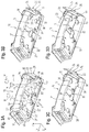
- the actuators 30, 30 ' are operated synchronously, as shown in FIG Figure 3A is symbolized by the curved double arrows M, so that all articulated levers 33, 33 'are pivoted synchronously.
- FIG 3B is this pivoting from the in Figure 3A
- the rest position shown takes place through a pivoting angle of approx. 20 °.
- the side section 24 of the left air guiding device part 20 was shifted predominantly in the direction of the vehicle transverse axis Y and slightly in the direction of the vehicle longitudinal axis X.
- the side section 24 has moved out of its parking position in a recess 13 formed by a side pocket 12 of the rear apron 10 in the lateral outer wall of the rear apron 10 to the side and slightly backwards against the direction of travel F.
- a rear apron 10 of a motor vehicle 1 is created which, when driving, especially at higher driving speeds, causes an aerodynamically effective and self-contained U-shaped extension of the contour of the vehicle rear both in the underbody area and on the sides of the vehicle.
- a robust kinematic solution is described that performs pivoting movements instead of translatory movements.
- the device according to the invention can also assume other forms of embodiment than those described above.
- the device can in particular have features that represent a combination of the respective individual features of the claims.
Claims (9)
- Véhicule automobile comprenant une jupe arrière (10) dont le contour peut être modifié au moyen d'un dispositif de guidage d'air (2), le dispositif de guidage d'air (2) pouvant être déplacé au moyen d'au moins une unité d'entraînement (3, 3') entre une position de repos en appui sur la jupe arrière (10) ou intégrée dans le contour de la jupe arrière (10) et une position de travail en saillie du contour de la jupe arrière (10), le dispositif de guidage d'air (2) comportant au moins une portion de base (22, 22') sur le côté inférieur de la jupe arrière (10) qui est dirigé vers la chaussée et une portion latérale gauche (24), vue dans le sens de roulement, et une portion latérale droite (24') sur le côté gauche, respectivement sur le côté droit, de la jupe arrière (10), les portions latérales (24, 24') étant reliées à l'au moins une portion de base (22, 22') de sorte que, dans la position de travail, une extension en forme de U du contour de la jupe arrière (10) soit formée dont le sens est opposé au sens de déplacement (F), caractérisé en ce que
l'au moins un dispositif d'entraînement (3, 3') comporte un dispositif de transmission (32, 32') qui est conçu de telle sorte que, lors d'un déplacement de la position de repos à la position de travail, les portions latérales (24, 24') soient écartées de la jupe arrière (10) et que l'au moins un dispositif de guidage d'air (2) effectue ensuite un déplacement vers l'arrière dans le sens opposé au sens de roulement (F). - Véhicule automobile selon la revendication 1, caractérisé en ce que
le dispositif de guidage d'air (2) est conçu pour être divisé dans la zone du plan médian longitudinal (XZ) du véhicule et comporte une partie gauche (20), vue dans le sens de roulement (F) et une partie droite (20') et en ce que
la partie respective (20, 20') du dispositif de guidage d'air comporte une portion de base inférieure (22, 22') qui se transforme, sur son côté extérieur (21, 21'), en la portion latérale associée (24.24'). - Véhicule automobile selon la revendication 2, caractérisé en ce que
la partie (20, 20') du dispositif de guidage d'air respective est associée à un dispositif d'entraînement indépendant (3, 3') pourvu à chaque fois d'un dispositif de transmission (32, 32'). - Véhicule automobile selon la revendication 3, caractérisé en ce que
le dispositif de transmission respectif (32, 32') est conçu de telle sorte que la partie (20, 20') du dispositif de guidage d'air sur laquelle il agit exécute un mouvement de pivotement lors duquel la portion latérale (24, 24') est d'abord principalement écartée de la jupe arrière (10) transversalement au plan médian longitudinal (XZ) du véhicule et lors duquel la partie (20, 20') du dispositif de guidage d'air effectue principalement un mouvement dans le sens opposé au sens de roulement (F). - Véhicule automobile selon la revendication 4, caractérisé en ce que
les parties respectives (20, 20') du dispositif de guidage d'air et le dispositif de transmission (32, 32') qui est associé à chacune d'elles sont conçus de telle sorte que la partie (20, 20') du dispositif de guidage d'air sur laquelle ledit dispositif de transmission agit effectue à nouveau un mouvement en direction du plan médian longitudinal (XZ) du véhicule vers la fin du mouvement de pivotement de sorte que la portion latérale (24, 24') vienne en contact, avec son bord avant (26, 26') en référence au sens de roulement (F), au moins par portions avec la jupe arrière (10). - Véhicule automobile selon la revendication 4 ou 5, caractérisé en ce que
les parties respectives (20, 20') du dispositif de guidage d'air et le dispositif de transmission (32, 32') qui est associé à chacune d'elles sont conçus de telle sorte que la partie (20, 20') du dispositif de guidage d'air sur laquelle ledit dispositif de transmission agit effectue à nouveau un mouvement en direction du plan médian longitudinal (XZ) du véhicule vers la fin du mouvement de pivotement de telle sorte que les deux parties (20, 20') du dispositif de guidage d'air viennent en appui l'une sur l'autre au niveau de leurs bords (23, 23') dirigés vers le plan médian longitudinal (XZ) du véhicule. - Ensemble destiné à être utilisé dans un véhicule automobile, l'ensemble comprenant un dispositif de guidage d'air (2), une jupe arrière (10) et au moins un dispositif d'entraînement (3, 3'), le contour de la jupe arrière (10) pouvant être modifié au moyen du dispositif de guidage d'air (2), le dispositif de guidage d'air (2) pouvant être déplacé au moyen de l'au moins un dispositif d'entraînement (3, 3') entre une position de repos en appui sur la jupe arrière (10) ou intégrée dans le contour de la jupe arrière (10) et une position de travail saillant du contour de la jupe arrière (10), le dispositif de guidage d'air (2) comportant au moins une portion de base inférieure (22, 22') et pour chacune d'elles, une portion latérale gauche respectivement droite (24, 24') reliée à la portion de base (22, 22'), les portions latérales (24, 24') étant reliées à l'au moins une portion de base (22, 22') de telle sorte que le dispositif de guidage d'air (2) comporte un contour sensiblement en forme de U,
caractérisé en ce que
l'au moins un dispositif d'entraînement (3, 3') comporte un dispositif de transmission (32, 32') qui est conçu de telle sorte que, lors d'un mouvement de la position de repos à la position de travail, les portions latérales (24, 24') sont d'abord écartées de la jupe arrière (10), et en ce que l'au moins un dispositif de guidage d'air (2) effectue ensuite un mouvement vers l'arrière dans le sens opposé au sens de roulement (F). - Ensemble selon la revendication 7,
caractérisé en ce que
le dispositif de guidage d'air (2) est conçu pour être divisé dans la zone de son plan médian longitudinal (XZ) et comporte une partie gauche (20) et une partie droite (20') et en ce que
la partie respective (20, 20') du dispositif de guidage d'air comporte une portion de base inférieure (22, 22') qui se transforme, sur son côté extérieur (21, 21'), en la portion latérale associée (24.24'). - Jupe arrière destinée à un véhicule automobile selon l'une des revendications 1 à 6 et/ou destinée à un ensemble selon la revendication 7 ou 8.
Applications Claiming Priority (1)
| Application Number | Priority Date | Filing Date | Title |
|---|---|---|---|
| DE102017201860.7A DE102017201860A1 (de) | 2017-02-07 | 2017-02-07 | Kraftfahrzeug mit einer Heckschürze |
Publications (2)
| Publication Number | Publication Date |
|---|---|
| EP3357800A1 EP3357800A1 (fr) | 2018-08-08 |
| EP3357800B1 true EP3357800B1 (fr) | 2020-12-23 |
Family
ID=61187201
Family Applications (1)
| Application Number | Title | Priority Date | Filing Date |
|---|---|---|---|
| EP18155579.8A Active EP3357800B1 (fr) | 2017-02-07 | 2018-02-07 | Véhicule automobile doté d'une jupe arrière |
Country Status (2)
| Country | Link |
|---|---|
| EP (1) | EP3357800B1 (fr) |
| DE (1) | DE102017201860A1 (fr) |
Families Citing this family (5)
| Publication number | Priority date | Publication date | Assignee | Title |
|---|---|---|---|---|
| DE102019104504A1 (de) * | 2019-02-22 | 2020-08-27 | Dr. Ing. H.C. F. Porsche Aktiengesellschaft | Kraftfahrzeug |
| DE102020103605A1 (de) | 2020-02-12 | 2021-08-12 | Bayerische Motoren Werke Aktiengesellschaft | Aufblasbares Fahrzeugkarosserieelement |
| EP4091920A1 (fr) * | 2021-05-18 | 2022-11-23 | Blue Technologies BV | Automobile ayant un élément mobile de guidage du vent |
| DE102021117255A1 (de) | 2021-07-05 | 2023-01-05 | Dr. Ing. H.C. F. Porsche Aktiengesellschaft | Kraftfahrzeug-Seitenspoileranordnung |
| DE102021117237A1 (de) | 2021-07-05 | 2023-01-05 | Dr. Ing. H.C. F. Porsche Aktiengesellschaft | Kraftfahrzeug-Seitenspoileranordnung |
Family Cites Families (8)
| Publication number | Priority date | Publication date | Assignee | Title |
|---|---|---|---|---|
| FR2028674A1 (fr) | 1969-01-17 | 1970-10-16 | Dumestre Andre | |
| US6196620B1 (en) | 1999-03-19 | 2001-03-06 | William H. Haraway, Jr. | Aerodynamically responsive vehicular undercarriage safety spoiler system |
| FR2880323B1 (fr) | 2004-12-31 | 2008-08-01 | Peugeot Citroen Automobiles Sa | Dispositif aerodynamique pour un vehicule automobile et vehicule automobile equipe d'un tel dispositif aerodynamique |
| DE102008012238A1 (de) | 2008-03-03 | 2009-09-10 | GM Global Technology Operations, Inc., Detroit | Heckdiffusoranordnung |
| JP2010143522A (ja) * | 2008-12-22 | 2010-07-01 | Toyota Motor Corp | 車体後部構造 |
| DE102010054686A1 (de) | 2010-12-16 | 2012-06-21 | GM Global Technology Operations LLC | Vorrichtung zum Einstellen aerodynamischer Eigenschaften eines Kraftfahrzeugs |
| DE102013101296A1 (de) | 2013-02-11 | 2014-08-14 | Dr. Ing. H.C. F. Porsche Aktiengesellschaft | Kraftfahrzeug mit einem heckseitigen Luftleitflügel |
| DE102013105842B4 (de) | 2013-06-06 | 2022-03-10 | Dr. Ing. H.C. F. Porsche Aktiengesellschaft | Kraftfahrzeug mit einem Heckdiffusor |
-
2017
- 2017-02-07 DE DE102017201860.7A patent/DE102017201860A1/de not_active Withdrawn
-
2018
- 2018-02-07 EP EP18155579.8A patent/EP3357800B1/fr active Active
Non-Patent Citations (1)
| Title |
|---|
| None * |
Also Published As
| Publication number | Publication date |
|---|---|
| EP3357800A1 (fr) | 2018-08-08 |
| DE102017201860A1 (de) | 2018-08-09 |
Similar Documents
| Publication | Publication Date | Title |
|---|---|---|
| EP3357800B1 (fr) | Véhicule automobile doté d'une jupe arrière | |
| EP2208655B1 (fr) | Arrangement de volet pour un véhicule ferroviaire, notamment pour un train à grande vitesse | |
| EP1840016B1 (fr) | Déflecteur aérodynamique pour véhicule | |
| EP2018289B1 (fr) | Entrainement pour deplacer un deflecteur d'air sur un cabriolet | |
| EP2765064B1 (fr) | Dispositif de guidage d'écoulement pour un véhicule ainsi que véhicule, en particulier poids lourd, semi-remorque de poids lourd, remorque de poids lourd ou fourgonnette | |
| DE102008024892B4 (de) | Luftleiteinrichtung | |
| DE102013106400A1 (de) | Spoiler für ein Kraftfahrzeug | |
| DE102005030203A1 (de) | Luftleitvorrichtung für ein Fahrzeug | |
| DE102016105994A1 (de) | Heckseitige Luftleiteinrichtung für ein Kraftfahrzeug | |
| DE102011011102A1 (de) | Luftleitanordnung | |
| DE102008011179A1 (de) | Heckspoileranordnung | |
| DE102011085933B4 (de) | Unterbodenverkleidung für ein Kraftfahrzeug mit beweglichen Teilen | |
| DE102006036453A1 (de) | Verfahrbares Dachelement für einen Personenkraftwagen | |
| DE102010032225B4 (de) | Aerodynamischer Körper mit Zusatzklappe | |
| DE102020103140A1 (de) | Luftleitvorrichtung für ein Kraftfahrzeug und Verfahren für eine Luftleitvorrichtung | |
| DE102008039480A1 (de) | Luftleitvorrichtung | |
| DE102010055231A1 (de) | Luftleitvorrichtung für ein Fahrzeug | |
| DE102014017518A1 (de) | Kraftfahrzeug | |
| DE102009057656A1 (de) | Luftführungseinrichtung an einem Personenkraftwagen sowie Verfahren zum Betreiben einer solchen Luftführungseinrichtung | |
| DE102019006675B4 (de) | Luftleiteinrichtung im Unterbodenbereich eines Kraftwagens | |
| EP2623390B1 (fr) | Elément de carrosserie pour une zone d'extrémité d'un véhicule sur rail et véhicule sur rail correspondant | |
| DE102010032224A1 (de) | Aerodynamischer Körper mit Zusatzklappe | |
| DE102012018465A1 (de) | Windleiteinrichtung | |
| WO2022089877A1 (fr) | Dispositif de guidage d'air pour voiture particulière, et voiture particulière | |
| DE102015012895B4 (de) | Verkleidungseinrichtung für ein Frontende eines Personenkraftwagens |
Legal Events
| Date | Code | Title | Description |
|---|---|---|---|
| PUAI | Public reference made under article 153(3) epc to a published international application that has entered the european phase |
Free format text: ORIGINAL CODE: 0009012 |
|
| STAA | Information on the status of an ep patent application or granted ep patent |
Free format text: STATUS: THE APPLICATION HAS BEEN PUBLISHED |
|
| AK | Designated contracting states |
Kind code of ref document: A1 Designated state(s): AL AT BE BG CH CY CZ DE DK EE ES FI FR GB GR HR HU IE IS IT LI LT LU LV MC MK MT NL NO PL PT RO RS SE SI SK SM TR |
|
| AX | Request for extension of the european patent |
Extension state: BA ME |
|
| STAA | Information on the status of an ep patent application or granted ep patent |
Free format text: STATUS: REQUEST FOR EXAMINATION WAS MADE |
|
| 17P | Request for examination filed |
Effective date: 20190208 |
|
| RBV | Designated contracting states (corrected) |
Designated state(s): AL AT BE BG CH CY CZ DE DK EE ES FI FR GB GR HR HU IE IS IT LI LT LU LV MC MK MT NL NO PL PT RO RS SE SI SK SM TR |
|
| STAA | Information on the status of an ep patent application or granted ep patent |
Free format text: STATUS: EXAMINATION IS IN PROGRESS |
|
| 17Q | First examination report despatched |
Effective date: 20190917 |
|
| GRAP | Despatch of communication of intention to grant a patent |
Free format text: ORIGINAL CODE: EPIDOSNIGR1 |
|
| STAA | Information on the status of an ep patent application or granted ep patent |
Free format text: STATUS: GRANT OF PATENT IS INTENDED |
|
| INTG | Intention to grant announced |
Effective date: 20200826 |
|
| GRAS | Grant fee paid |
Free format text: ORIGINAL CODE: EPIDOSNIGR3 |
|
| GRAA | (expected) grant |
Free format text: ORIGINAL CODE: 0009210 |
|
| STAA | Information on the status of an ep patent application or granted ep patent |
Free format text: STATUS: THE PATENT HAS BEEN GRANTED |
|
| AK | Designated contracting states |
Kind code of ref document: B1 Designated state(s): AL AT BE BG CH CY CZ DE DK EE ES FI FR GB GR HR HU IE IS IT LI LT LU LV MC MK MT NL NO PL PT RO RS SE SI SK SM TR |
|
| REG | Reference to a national code |
Ref country code: GB Ref legal event code: FG4D Free format text: NOT ENGLISH |
|
| RIN1 | Information on inventor provided before grant (corrected) |
Inventor name: SEITZ, CHRISTIAN Inventor name: HUCK, OLIVER Inventor name: SCHLEMMER, ANNA Inventor name: PROF. DR.SCHUETZ, THOMAS Inventor name: GALITZ, MARKUS |
|
| REG | Reference to a national code |
Ref country code: DE Ref legal event code: R096 Ref document number: 502018003367 Country of ref document: DE |
|
| REG | Reference to a national code |
Ref country code: AT Ref legal event code: REF Ref document number: 1347447 Country of ref document: AT Kind code of ref document: T Effective date: 20210115 |
|
| REG | Reference to a national code |
Ref country code: IE Ref legal event code: FG4D Free format text: LANGUAGE OF EP DOCUMENT: GERMAN |
|
| PG25 | Lapsed in a contracting state [announced via postgrant information from national office to epo] |
Ref country code: RS Free format text: LAPSE BECAUSE OF FAILURE TO SUBMIT A TRANSLATION OF THE DESCRIPTION OR TO PAY THE FEE WITHIN THE PRESCRIBED TIME-LIMIT Effective date: 20201223 Ref country code: FI Free format text: LAPSE BECAUSE OF FAILURE TO SUBMIT A TRANSLATION OF THE DESCRIPTION OR TO PAY THE FEE WITHIN THE PRESCRIBED TIME-LIMIT Effective date: 20201223 Ref country code: NO Free format text: LAPSE BECAUSE OF FAILURE TO SUBMIT A TRANSLATION OF THE DESCRIPTION OR TO PAY THE FEE WITHIN THE PRESCRIBED TIME-LIMIT Effective date: 20210323 Ref country code: GR Free format text: LAPSE BECAUSE OF FAILURE TO SUBMIT A TRANSLATION OF THE DESCRIPTION OR TO PAY THE FEE WITHIN THE PRESCRIBED TIME-LIMIT Effective date: 20210324 |
|
| REG | Reference to a national code |
Ref country code: NL Ref legal event code: MP Effective date: 20201223 |
|
| PG25 | Lapsed in a contracting state [announced via postgrant information from national office to epo] |
Ref country code: BG Free format text: LAPSE BECAUSE OF FAILURE TO SUBMIT A TRANSLATION OF THE DESCRIPTION OR TO PAY THE FEE WITHIN THE PRESCRIBED TIME-LIMIT Effective date: 20210323 Ref country code: LV Free format text: LAPSE BECAUSE OF FAILURE TO SUBMIT A TRANSLATION OF THE DESCRIPTION OR TO PAY THE FEE WITHIN THE PRESCRIBED TIME-LIMIT Effective date: 20201223 Ref country code: SE Free format text: LAPSE BECAUSE OF FAILURE TO SUBMIT A TRANSLATION OF THE DESCRIPTION OR TO PAY THE FEE WITHIN THE PRESCRIBED TIME-LIMIT Effective date: 20201223 |
|
| PG25 | Lapsed in a contracting state [announced via postgrant information from national office to epo] |
Ref country code: HR Free format text: LAPSE BECAUSE OF FAILURE TO SUBMIT A TRANSLATION OF THE DESCRIPTION OR TO PAY THE FEE WITHIN THE PRESCRIBED TIME-LIMIT Effective date: 20201223 Ref country code: NL Free format text: LAPSE BECAUSE OF FAILURE TO SUBMIT A TRANSLATION OF THE DESCRIPTION OR TO PAY THE FEE WITHIN THE PRESCRIBED TIME-LIMIT Effective date: 20201223 |
|
| REG | Reference to a national code |
Ref country code: LT Ref legal event code: MG9D |
|
| PG25 | Lapsed in a contracting state [announced via postgrant information from national office to epo] |
Ref country code: LT Free format text: LAPSE BECAUSE OF FAILURE TO SUBMIT A TRANSLATION OF THE DESCRIPTION OR TO PAY THE FEE WITHIN THE PRESCRIBED TIME-LIMIT Effective date: 20201223 Ref country code: CZ Free format text: LAPSE BECAUSE OF FAILURE TO SUBMIT A TRANSLATION OF THE DESCRIPTION OR TO PAY THE FEE WITHIN THE PRESCRIBED TIME-LIMIT Effective date: 20201223 Ref country code: EE Free format text: LAPSE BECAUSE OF FAILURE TO SUBMIT A TRANSLATION OF THE DESCRIPTION OR TO PAY THE FEE WITHIN THE PRESCRIBED TIME-LIMIT Effective date: 20201223 Ref country code: SM Free format text: LAPSE BECAUSE OF FAILURE TO SUBMIT A TRANSLATION OF THE DESCRIPTION OR TO PAY THE FEE WITHIN THE PRESCRIBED TIME-LIMIT Effective date: 20201223 Ref country code: RO Free format text: LAPSE BECAUSE OF FAILURE TO SUBMIT A TRANSLATION OF THE DESCRIPTION OR TO PAY THE FEE WITHIN THE PRESCRIBED TIME-LIMIT Effective date: 20201223 Ref country code: PT Free format text: LAPSE BECAUSE OF FAILURE TO SUBMIT A TRANSLATION OF THE DESCRIPTION OR TO PAY THE FEE WITHIN THE PRESCRIBED TIME-LIMIT Effective date: 20210423 Ref country code: SK Free format text: LAPSE BECAUSE OF FAILURE TO SUBMIT A TRANSLATION OF THE DESCRIPTION OR TO PAY THE FEE WITHIN THE PRESCRIBED TIME-LIMIT Effective date: 20201223 |
|
| PG25 | Lapsed in a contracting state [announced via postgrant information from national office to epo] |
Ref country code: PL Free format text: LAPSE BECAUSE OF FAILURE TO SUBMIT A TRANSLATION OF THE DESCRIPTION OR TO PAY THE FEE WITHIN THE PRESCRIBED TIME-LIMIT Effective date: 20201223 |
|
| REG | Reference to a national code |
Ref country code: DE Ref legal event code: R097 Ref document number: 502018003367 Country of ref document: DE |
|
| PG25 | Lapsed in a contracting state [announced via postgrant information from national office to epo] |
Ref country code: MC Free format text: LAPSE BECAUSE OF FAILURE TO SUBMIT A TRANSLATION OF THE DESCRIPTION OR TO PAY THE FEE WITHIN THE PRESCRIBED TIME-LIMIT Effective date: 20201223 Ref country code: IS Free format text: LAPSE BECAUSE OF FAILURE TO SUBMIT A TRANSLATION OF THE DESCRIPTION OR TO PAY THE FEE WITHIN THE PRESCRIBED TIME-LIMIT Effective date: 20210423 |
|
| REG | Reference to a national code |
Ref country code: BE Ref legal event code: MM Effective date: 20210228 |
|
| PG25 | Lapsed in a contracting state [announced via postgrant information from national office to epo] |
Ref country code: AL Free format text: LAPSE BECAUSE OF FAILURE TO SUBMIT A TRANSLATION OF THE DESCRIPTION OR TO PAY THE FEE WITHIN THE PRESCRIBED TIME-LIMIT Effective date: 20201223 Ref country code: CH Free format text: LAPSE BECAUSE OF NON-PAYMENT OF DUE FEES Effective date: 20210228 Ref country code: LI Free format text: LAPSE BECAUSE OF NON-PAYMENT OF DUE FEES Effective date: 20210228 Ref country code: LU Free format text: LAPSE BECAUSE OF NON-PAYMENT OF DUE FEES Effective date: 20210207 |
|
| PLBE | No opposition filed within time limit |
Free format text: ORIGINAL CODE: 0009261 |
|
| STAA | Information on the status of an ep patent application or granted ep patent |
Free format text: STATUS: NO OPPOSITION FILED WITHIN TIME LIMIT |
|
| PG25 | Lapsed in a contracting state [announced via postgrant information from national office to epo] |
Ref country code: DK Free format text: LAPSE BECAUSE OF FAILURE TO SUBMIT A TRANSLATION OF THE DESCRIPTION OR TO PAY THE FEE WITHIN THE PRESCRIBED TIME-LIMIT Effective date: 20201223 |
|
| 26N | No opposition filed |
Effective date: 20210924 |
|
| PG25 | Lapsed in a contracting state [announced via postgrant information from national office to epo] |
Ref country code: ES Free format text: LAPSE BECAUSE OF FAILURE TO SUBMIT A TRANSLATION OF THE DESCRIPTION OR TO PAY THE FEE WITHIN THE PRESCRIBED TIME-LIMIT Effective date: 20201223 Ref country code: IE Free format text: LAPSE BECAUSE OF NON-PAYMENT OF DUE FEES Effective date: 20210207 |
|
| PG25 | Lapsed in a contracting state [announced via postgrant information from national office to epo] |
Ref country code: SI Free format text: LAPSE BECAUSE OF FAILURE TO SUBMIT A TRANSLATION OF THE DESCRIPTION OR TO PAY THE FEE WITHIN THE PRESCRIBED TIME-LIMIT Effective date: 20201223 |
|
| PG25 | Lapsed in a contracting state [announced via postgrant information from national office to epo] |
Ref country code: IS Free format text: LAPSE BECAUSE OF FAILURE TO SUBMIT A TRANSLATION OF THE DESCRIPTION OR TO PAY THE FEE WITHIN THE PRESCRIBED TIME-LIMIT Effective date: 20210423 |
|
| PG25 | Lapsed in a contracting state [announced via postgrant information from national office to epo] |
Ref country code: BE Free format text: LAPSE BECAUSE OF NON-PAYMENT OF DUE FEES Effective date: 20210228 |
|
| PGFP | Annual fee paid to national office [announced via postgrant information from national office to epo] |
Ref country code: FR Payment date: 20230220 Year of fee payment: 6 |
|
| PGFP | Annual fee paid to national office [announced via postgrant information from national office to epo] |
Ref country code: IT Payment date: 20230228 Year of fee payment: 6 Ref country code: GB Payment date: 20230221 Year of fee payment: 6 Ref country code: DE Payment date: 20230214 Year of fee payment: 6 |
|
| P01 | Opt-out of the competence of the unified patent court (upc) registered |
Effective date: 20230502 |
|
| PG25 | Lapsed in a contracting state [announced via postgrant information from national office to epo] |
Ref country code: CY Free format text: LAPSE BECAUSE OF FAILURE TO SUBMIT A TRANSLATION OF THE DESCRIPTION OR TO PAY THE FEE WITHIN THE PRESCRIBED TIME-LIMIT Effective date: 20201223 |
|
| PG25 | Lapsed in a contracting state [announced via postgrant information from national office to epo] |
Ref country code: HU Free format text: LAPSE BECAUSE OF FAILURE TO SUBMIT A TRANSLATION OF THE DESCRIPTION OR TO PAY THE FEE WITHIN THE PRESCRIBED TIME-LIMIT; INVALID AB INITIO Effective date: 20180207 |
|
| REG | Reference to a national code |
Ref country code: AT Ref legal event code: MM01 Ref document number: 1347447 Country of ref document: AT Kind code of ref document: T Effective date: 20230207 |