EP3356587B1 - Verfahren und vorrichtung zur herstellung einer schlauchförmigen gestrickten textilstruktur - Google Patents
Verfahren und vorrichtung zur herstellung einer schlauchförmigen gestrickten textilstruktur Download PDFInfo
- Publication number
- EP3356587B1 EP3356587B1 EP16787488.2A EP16787488A EP3356587B1 EP 3356587 B1 EP3356587 B1 EP 3356587B1 EP 16787488 A EP16787488 A EP 16787488A EP 3356587 B1 EP3356587 B1 EP 3356587B1
- Authority
- EP
- European Patent Office
- Prior art keywords
- tubular
- loom
- textile structure
- producing
- needle bed
- Prior art date
- Legal status (The legal status is an assumption and is not a legal conclusion. Google has not performed a legal analysis and makes no representation as to the accuracy of the status listed.)
- Active
Links
Images

Classifications
-
- D—TEXTILES; PAPER
- D04—BRAIDING; LACE-MAKING; KNITTING; TRIMMINGS; NON-WOVEN FABRICS
- D04B—KNITTING
- D04B23/00—Flat warp knitting machines
- D04B23/12—Flat warp knitting machines with provision for incorporating unlooped wefts extending from selvedge to selvedge
Definitions
- the present invention falls within the field of the production of tubular textile structures, produced by knitting, using the so-called "warp knit” technology. It also relates to a device implementing this method.
- the textiles obtained due to the diagonal arrangement of the threads, have a certain extensibility and a diameter that is not perfectly defined.
- This diameter is, in addition, determined by that of the loom. Changing the diameter requires choosing another machine, without allowing intermediate adjustments to be made.
- the diameter of the resulting tubular structure is only approximately controlled, and moreover, there is always a greater or lesser possibility of radial extension of said structure. In addition, the mechanical properties always remain limited in this radial direction.
- the braiding technique requires a choice of constituents of materials of the same nature, thereby limiting the possible combinations and, consequently, the applications likely to result from such tubular structures.
- the objective sought by the present invention is to allow the production of such a tubular textile structure developing a controlled extensibility of its diameter, therefore in the radial direction, and capable in addition of developing mechanical properties impossible to achieve with the techniques of the prior art.
- the method of the invention consists in producing a 3D structure by using a double-bed knitting machine, typically a Rachel machine, using known technology called warp knitting, then in weaving the resulting 3D structure using a continuous weft, the continuity of the weft yarn making it possible in particular to effectively control the strength and elongation properties of the tubular structure.
- the properties are thus directly identical or in any case very close to the characteristics of the weft yarn, with the wefting being almost zero.
- this process makes it possible to vary the choice of materials used and in particular to differentiate the threads constituting the structure obtained on the double-bed Rachel loom and the weft thread, thus making it possible to multiply the possible applications of the tubular structure and, consequently, its properties, in particular physical or mechanical.
- the method of the invention makes it possible to obtain a tubular structure whose mechanical properties are controlled in two directions.
- multi-tubular structure is meant the production of structures having not one but several tubes extending substantially parallel to each other, said tubes being capable of being separated from each other after their production.
- the joining of the two plies can take place at their lateral edges, with a view to eventually forming a tubular structure. But this joining can also take place in the intermediate zone, so as to produce a multi-tubular structure.
- This joining is carried out using threads called in the field considered by "pile threads". These are the usual connecting threads distributed on a single or on several bars of a double-bed loom. These threads pass alternately through the movement of the loom from one bed to the other to create a textile having a thickness.
- the person skilled in the art will know how to apply without difficulty the different possible connections to stiffen this connection as required and possibly keep it completely homogeneous with the weave of each of the two faces. It is also possible to choose a thread of different count or even of different nature in order to obtain the appropriate resistance.
- the invention also relates to devices allowing the production of such a knitted tubular structure in accordance with the aforementioned method, according to claims 8 and 9.
- the device according to the invention uses a rotary wefter describing rotations around the double needle bed, in order to insert a weft thread in a helix on the 3D structure, in a continuous manner.
- the nature of the threads constituting the 3D structure is identical or different from that of the weft thread.
- the weft yarn supply spool is mounted on a circular crown in the center of which the double needle bed is mounted, the circular crown being rotated by any means, such as in particular by gear with toothed pinions on a toothing arranged on the external periphery of the crown.
- the weft yarn supply bobbin is mounted on a carriage guided on guide means surrounding the double needle bed, said carriage being moved on said guide means by any means such as a toothed belt or rack and pinions.
- the invention also relates to any tubular knitted textile structure obtained using the process in accordance with the invention.
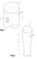
- this tubular structure results from a 3D structure 2 obtained by warp knitting technology on a double-bed Rachel loom, made from a binding based on chains combined with sectional wefts or a binding of the simple knitting, double knitting or other type, depending on the texture and the mechanical performances (strength, elongation) desired, and this, in a known manner.
- the tubular structure also comprises a continuous helical weft 3, here shown with a constant pitch 4.
- Both the pitch and the inclination or obliquity of the helix of the weft can be programmed to vary along the textile structure depending on the applications envisaged.
- This continuous frame 3 makes it possible to limit, or even prohibit, depending on the nature of the wire which constitutes it, any extensibility of the structure in the radial direction, that is to say any expansion of the diameter of the tube.
- Rachel looms can be equipped with different gauges, that is to say, with a greater or lesser number of needles and knitting elements, allowing a great variability of performance adjustment, but also permeabilities by the rate of opening of the stitches.
- One of the essential elements of the invention lies in the continuous nature of the weft thread, which is therefore inserted over the entire circumference of the 3D textile structure manufactured on the double-bed type Rachel loom and thus making it possible to reinforce its mechanical resistance because it is free from any interruption resulting from the cutting of the weft threads observed in the technologies of the prior art.
- the two zones A and C each have a constant but different diameter, by playing on the binding and control of the flow rates of the 3D structure or the weft thread and their tension.
- These two zones are connected to each other continuously by zone B.
- the weft thread is also present but can be programmed with a different “pitch” if necessary.
- the pitch of the helix formed by the weft thread 3 can vary from zone A to zone C, so as to give these two zones different properties, for example mechanical properties.
- FIGS. 3a and 3b illustrate different variants of the tubular structure of the invention.
- the Figure 3a illustrates a tubular structure, provided with two lateral tabs 25, 26, resulting from the joining of the two textile faces obtained by the double-bed Rachel loom. These tabs are capable of constituting reinforced zones suitable for allowing the tubular structure to be fixed depending on the applications envisaged.
- the continuous weft again runs around the entire circumference of the textile structure, including at the level of these tabs.
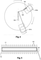
- the supply reel 7 for weft thread 3 is arranged in a plane perpendicular to that receiving the double beds and passing at the level of the cooperation zone of the needles and the guides of said beds.
- the rotary movement of the bobbin 7 around the two needle beds is obtained by any means, and in any event, by a mechanism synchronized with the cycle of formation of the stitches on the double needle bed loom.
- This bobbin 7 delivers the weft thread 3 after passing through a braking device 8, in order to ensure correct tension of the weft thread.
- This braking is carried out either directly on the weft thread, or on the bobbin itself.
- Such braking systems are known per se. They can be in particular of a mechanical, electrical or even electromagnetic nature.
- the programming of the helix pitch resulting from the insertion of this weft thread can in particular be a direct consequence of the sequences of introduction of the weft in question into the knitting program of the 3D background structure.
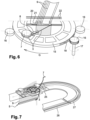
- This double bed has also been schematically represented in a top view on the figure 5 .
- the front 10 and rear 11 needle beds have thus been materialized, at the level of which the knitting threads 9 of the 3D support structure appear, as well as the schematic arrangement of the weft thread 3 inserted by means of the device which is the subject of the present invention.
- the feed reel 7 for weft yarn 3 is mounted on a circular crown 15.
- This circular crown is therefore mounted around the double-bed loom 5. It is rotated by means of toothed pinions 16 whose rotation axis 17 is actuated by electric motors (not shown). These toothed pinions 16 mesh with the toothed peripheral edge 18 of said crown 15.
- the management of the electric motor(s) actuating the toothed pinions 16 is synchronized with the operating cycle of the double-bed loom, so as to introduce the weft yarn 3 at the appropriate time at each of the beds.
- the weft thread 3 performs a revolution, and in the example described a rotation, around the needle beds in the area where the 3D textile structure obtained by the play of the knitting members mounted on needle beds, respectively needles 20 and guides 21, is produced.
- the guides are themselves moved on support bars 22, according to the selected thread binding program.
- This figure also shows the braking device 8 positioned at the outlet of the bobbin, for the purpose of regulating the tension of the weft thread.
- the supply reel 7 of weft thread 3 is mounted on a carriage 25 guided according to a guidance system, in this case, in the form of a racetrack, and typically consisting of rectilinear portions 26 and curvilinear portions 27, suitable for constituting a continuous path for said carriage 25, and consequently for the reel 7.
- the carriage 25 also ensures revolutions around the double-bed loom, like the embodiment previously described.
- the carriage 25 is secured to a toothed belt or any other equivalent device, cooperating with a suitable roller (not shown), or any other means capable of ensuring its progression on the guide path 26, 27.
- the weft reel support carriage is then released at the end of the rectilinear travel 26 to be taken over by another means of transport on the crown 27.
- This embodiment is particularly advantageous for the production of tubular textile structures of great width or large diameter, allowing in particular the use of linear motors or motors with high speed control by appropriate electronics.
- the invention also relates to the tubular textile structures obtained by the process described above.
Landscapes
- Engineering & Computer Science (AREA)
- Textile Engineering (AREA)
- Knitting Machines (AREA)
- Looms (AREA)
- Woven Fabrics (AREA)
Claims (9)
- Verfahren zur Herstellung einer schlauchförmigen gestrickten Textilstruktur (1), das aus folgenden Schritten besteht:- zunächst auf einer Doppelbett-Raschelmaschine (5) zwei Lagen mittels Kettenwirkverfahren herzustellen, die durch Verbindungsfäden miteinander verbunden sind, die durch die Bewegung der Maschine abwechselnd von einem Nadelbett zum anderen laufen, um ein Textil zu schaffen, das eine Dicke aufweist, die eine 3D-Struktur (2) bildet, um schließlich eine schlauchförmige oder mehrfach schlauchförmige Struktur zu definieren, das heißt eine Struktur, die mehrere zueinander im Wesentlichen parallele Schläuche aufweist, wobei die Schläuche nach ihrer Herstellung voneinander getrennt werden können;- und einen fortlaufenden Schuss (3) im Bereich des Doppelbetts einzufügen, der in die Maschen an den beiden Lagen mit Versatz in Produktionsrichtung eingefügt wird, wobei der fortlaufende Schuss im Bereich der Nadelbetten durch Umlaufen um die Nadelbetten herum geführt wird.
- Verfahren zur Herstellung einer schlauchförmigen gestrickten Textilstruktur (1) nach Anspruch 1, dadurch gekennzeichnet, dass die Verbindung der beiden Lagen im Hinblick auf die spätere Bildung einer schlauchförmigen oder mehrfach schlauchförmigen Struktur mithilfe von Verbindungsfäden erfolgt, die über Zwischenpunkte zum Einsatz kommen.
- Verfahren zur Herstellung einer schlauchförmigen gestrickten Textilstruktur (1) nach einem der Ansprüche 1 oder 2, dadurch gekennzeichnet, dass der Schuss (3) innerhalb der 3D-Struktur helikal in Bezug auf die Produktionsrichtung der Struktur eingefügt wird.
- Verfahren zur Herstellung einer schlauchförmigen gestrickten Textilstruktur (1) nach Anspruch 3, dadurch gekennzeichnet, dass die Helixsteigung (4) konstant ist.
- Verfahren zur Herstellung einer schlauchförmigen gestrickten Textilstruktur (1) nach Anspruch 3, dadurch gekennzeichnet, dass die Helixsteigung (4) einstellbar ist und während der Herstellung der Textilstruktur veränderbar ist.
- Verfahren zur Herstellung einer schlauchförmigen gestrickten Textilstruktur (1) nach einem der Ansprüche 1 bis 5, dadurch gekennzeichnet, dass die Art der die 3D-Struktur (2) bildenden Fäden mit der des Schussfadens (3) identisch oder von dieser verschieden ist.
- Gestrickte schlauchförmige Textilstruktur (1), die nach dem Verfahren gemäß einem der Ansprüche 1 bis 6 erhalten wird.
- Vorrichtung zur Herstellung einer schlauchförmigen gestrickten Textilstruktur (1) nach Anspruch 7, umfassend:- eine Doppelbett-Rachelmaschine (5), der Fäden (9) zugeführt werden, so dass eine 3D-Textilstruktur (2) erzeugt wird,- eine Spule (7) zum Zuführen des Schussfadens (3) der auf der Doppelbett-Rachelmaschine hergestellten 3D-Struktur, wobei die Spule gleichzeitig mit der Herstellung der 3D-Textilstruktur einer Bewegung vom Typ Umlauf um die Doppelbettmaschine (5) unterzogen wird, so dass sie mit den Strickorganen (20, 21) der beiden Nadelbetten zusammenwirkt, wobei die Spule (7) auf einem kreisförmigen Kranz (15) montiert ist, in dessen Mitte die Doppelbettmaschine (5) montiert ist, wobei der kreisförmige Kranz (15) durch beliebige Mittel in Drehung versetzt wird, wie beispielsweise insbesondere durch ein Getriebe mit Zahnrädern (16), die in eine am Außenumfang des Kranzes ausgebildete Verzahnung (18) eingreifen.
- Vorrichtung zur Herstellung einer schlauchförmigen gestrickten Textilstruktur (1) nach Anspruch 7, umfassend:- eine Doppelbett-Rachelmaschine (5), der Fäden (9) zugeführt werden, so dass eine 3D-Textilstruktur (2) erzeugt wird,- eine Spule (7) zum Zuführen des Schussfadens (3) der auf der Doppelbett-Rachelmaschine hergestellten 3D-Struktur, wobei die Spule gleichzeitig mit der Herstellung der 3D-Textilstruktur einer Bewegung vom Typ Umlauf um die Doppelbettmaschine (5) unterzogen wird, so dass sie mit den Strickorganen (20, 21) der beiden Nadelbetten zusammenwirkt, wobei die Spule (7) auf einem Schlitten (25) montiert ist, der auf einer Führungsbahn (26, 27) geführt wird, die die Doppelbettmaschine (5) umgibt, wobei der Schlitten auf der Führungsbahn durch beliebige Mittel wie Zahnriemen oder Zahnstange und Zahnräder verschoben wird.
Applications Claiming Priority (2)
| Application Number | Priority Date | Filing Date | Title |
|---|---|---|---|
| FR1559096A FR3041663B1 (fr) | 2015-09-28 | 2015-09-28 | Procede et dispositif pour la realisation d'une structure textile tricotee tubulaire |
| PCT/FR2016/052433 WO2017055722A1 (fr) | 2015-09-28 | 2016-09-26 | Procede et dispositif pour la realisation d'une structure textile tricotee tubulaire |
Publications (3)
| Publication Number | Publication Date |
|---|---|
| EP3356587A1 EP3356587A1 (de) | 2018-08-08 |
| EP3356587C0 EP3356587C0 (de) | 2025-02-12 |
| EP3356587B1 true EP3356587B1 (de) | 2025-02-12 |
Family
ID=54707980
Family Applications (1)
| Application Number | Title | Priority Date | Filing Date |
|---|---|---|---|
| EP16787488.2A Active EP3356587B1 (de) | 2015-09-28 | 2016-09-26 | Verfahren und vorrichtung zur herstellung einer schlauchförmigen gestrickten textilstruktur |
Country Status (3)
| Country | Link |
|---|---|
| EP (1) | EP3356587B1 (de) |
| FR (1) | FR3041663B1 (de) |
| WO (1) | WO2017055722A1 (de) |
Families Citing this family (2)
| Publication number | Priority date | Publication date | Assignee | Title |
|---|---|---|---|---|
| US11530501B1 (en) * | 2017-10-02 | 2022-12-20 | Apple Inc. | Tubular warp knit spacer fabric |
| FR3071716B1 (fr) * | 2017-10-04 | 2023-02-24 | Mdb Texinov | Insert textile a finalite medicale et son procede de fabrication |
Family Cites Families (4)
| Publication number | Priority date | Publication date | Assignee | Title |
|---|---|---|---|---|
| US2560311A (en) * | 1951-07-10 | Mechanism for the manufacture of | ||
| GB1183890A (en) * | 1967-12-20 | 1970-03-11 | Mayer Textilmaschf | Seamless Net Tube |
| US4100770A (en) * | 1976-10-28 | 1978-07-18 | E. I. Du Pont De Nemours And Company | Process and nonraveling knit tubular products having axial stretch |
| WO1991005595A1 (fr) * | 1989-10-13 | 1991-05-02 | Mitsubishi Rayon Co., Ltd. | Procede et appareil de production d'articles tricotes en film de fil creux |
-
2015
- 2015-09-28 FR FR1559096A patent/FR3041663B1/fr not_active Expired - Fee Related
-
2016
- 2016-09-26 WO PCT/FR2016/052433 patent/WO2017055722A1/fr not_active Ceased
- 2016-09-26 EP EP16787488.2A patent/EP3356587B1/de active Active
Also Published As
| Publication number | Publication date |
|---|---|
| FR3041663B1 (fr) | 2018-04-27 |
| FR3041663A1 (fr) | 2017-03-31 |
| EP3356587C0 (de) | 2025-02-12 |
| EP3356587A1 (de) | 2018-08-08 |
| WO2017055722A1 (fr) | 2017-04-06 |
Similar Documents
| Publication | Publication Date | Title |
|---|---|---|
| EP2791403B1 (de) | Webstuhl mit optimierter kettenwebung | |
| EP1163385B1 (de) | Schräges gewebe, verfahren und webmaschine zur kontinuierlichen herstellung eines solchen gewebes | |
| FR3062659A1 (fr) | Appel de preforme dans un metier a tisser du type jacquard | |
| EP3356587B1 (de) | Verfahren und vorrichtung zur herstellung einer schlauchförmigen gestrickten textilstruktur | |
| CH648880A5 (fr) | Predelivreur-mesureur de trame pour machine a tisser sans navette. | |
| FR1465855A (fr) | Tissu à bouclettes de poil sur les deux faces | |
| EP0045758B1 (de) | Vorrichtung zum heben der kettfäden in einem webstuhl und mit einer solchen vorrichtung ausgerüsteter webstuhl | |
| WO2017149252A1 (fr) | Installation et procede pour la fabrication d'une texture fibreuse en forme de bande presentant en section transversale un profil evolutif | |
| EP0530120B1 (de) | Textile schlauchförmige Bewehrung für Materialverstärkung und Vorrichtung zu ihrer Herstellung | |
| EP0230803A1 (de) | Mehrschichtiger, textiler Gegenstand für die Herstellung von Schichtmaterialien, Verfahren und Vorrichtung zur Herstellung desselben | |
| EP0082794B1 (de) | Vorrichtung zur Herstellung eines aus parallelen Fäden gebildeten Vlieses und Verfahren zur Herstellung von verschiedenen zusammengesetzten, ein solches Vlies enthaltenden Produkten | |
| FR2785914A1 (fr) | Dispositif d'amenee d'une couche de fils multicouche, multi-axiale a l'emplacement de tricotage d'un metier a tricoter chaine | |
| FR2684696A1 (fr) | Procede pour la realisation d'un article tricote a base de fils metalliques et nouveau type de tricot ainsi realise. | |
| EP1918432B1 (de) | Verfahren zur Behandlung von Garnen durch Knit-Deknit-Strukturierung | |
| EP1598460B1 (de) | Vorrichting zum Antrieb von Stricknadeln und Webmaschine mit einer solchen Vorrichtung | |
| FR2884836A1 (fr) | Tresseuse circulaire multicouche | |
| EP1857579B1 (de) | Verfahren zur Herstellung eines Textilartikels zur Verstärkung, mit diesem Verfahren erhaltener Textilartikel und Maschine zur Herstellung eines solchen Artikels | |
| FR2899603A1 (fr) | Fil reliefe, et procede de fabrication | |
| WO2006035169A1 (fr) | Materiau plan textile notamment pour ecran lumineux et son procede de fabrication | |
| FR2921676A1 (fr) | Dispositif de formation d'un non-tisse. | |
| BE637625A (de) | ||
| FR2549103A1 (fr) | Machine pour la fabrication de tissus a mailles et a tissage | |
| FR2932063A1 (fr) | Filet pre-assemble et procede de pre-assemblage des mailles d'un filet | |
| BE386210A (de) | ||
| BE341300A (de) |
Legal Events
| Date | Code | Title | Description |
|---|---|---|---|
| STAA | Information on the status of an ep patent application or granted ep patent |
Free format text: STATUS: UNKNOWN |
|
| STAA | Information on the status of an ep patent application or granted ep patent |
Free format text: STATUS: THE INTERNATIONAL PUBLICATION HAS BEEN MADE |
|
| PUAI | Public reference made under article 153(3) epc to a published international application that has entered the european phase |
Free format text: ORIGINAL CODE: 0009012 |
|
| STAA | Information on the status of an ep patent application or granted ep patent |
Free format text: STATUS: REQUEST FOR EXAMINATION WAS MADE |
|
| 17P | Request for examination filed |
Effective date: 20180123 |
|
| AK | Designated contracting states |
Kind code of ref document: A1 Designated state(s): AL AT BE BG CH CY CZ DE DK EE ES FI FR GB GR HR HU IE IS IT LI LT LU LV MC MK MT NL NO PL PT RO RS SE SI SK SM TR |
|
| AX | Request for extension of the european patent |
Extension state: BA ME |
|
| DAV | Request for validation of the european patent (deleted) | ||
| DAX | Request for extension of the european patent (deleted) | ||
| STAA | Information on the status of an ep patent application or granted ep patent |
Free format text: STATUS: EXAMINATION IS IN PROGRESS |
|
| 17Q | First examination report despatched |
Effective date: 20211014 |
|
| GRAP | Despatch of communication of intention to grant a patent |
Free format text: ORIGINAL CODE: EPIDOSNIGR1 |
|
| STAA | Information on the status of an ep patent application or granted ep patent |
Free format text: STATUS: GRANT OF PATENT IS INTENDED |
|
| GRAS | Grant fee paid |
Free format text: ORIGINAL CODE: EPIDOSNIGR3 |
|
| INTG | Intention to grant announced |
Effective date: 20241205 |
|
| GRAA | (expected) grant |
Free format text: ORIGINAL CODE: 0009210 |
|
| STAA | Information on the status of an ep patent application or granted ep patent |
Free format text: STATUS: THE PATENT HAS BEEN GRANTED |
|
| AK | Designated contracting states |
Kind code of ref document: B1 Designated state(s): AL AT BE BG CH CY CZ DE DK EE ES FI FR GB GR HR HU IE IS IT LI LT LU LV MC MK MT NL NO PL PT RO RS SE SI SK SM TR |
|
| REG | Reference to a national code |
Ref country code: GB Ref legal event code: FG4D Free format text: NOT ENGLISH |
|
| REG | Reference to a national code |
Ref country code: CH Ref legal event code: EP |
|
| REG | Reference to a national code |
Ref country code: DE Ref legal event code: R096 Ref document number: 602016091201 Country of ref document: DE |
|
| REG | Reference to a national code |
Ref country code: IE Ref legal event code: FG4D Free format text: LANGUAGE OF EP DOCUMENT: FRENCH |
|
| U01 | Request for unitary effect filed |
Effective date: 20250212 |
|
| U07 | Unitary effect registered |
Designated state(s): AT BE BG DE DK EE FI FR IT LT LU LV MT NL PT RO SE SI Effective date: 20250218 |
|
| PG25 | Lapsed in a contracting state [announced via postgrant information from national office to epo] |
Ref country code: RS Free format text: LAPSE BECAUSE OF FAILURE TO SUBMIT A TRANSLATION OF THE DESCRIPTION OR TO PAY THE FEE WITHIN THE PRESCRIBED TIME-LIMIT Effective date: 20250512 |
|
| PG25 | Lapsed in a contracting state [announced via postgrant information from national office to epo] |
Ref country code: PL Free format text: LAPSE BECAUSE OF FAILURE TO SUBMIT A TRANSLATION OF THE DESCRIPTION OR TO PAY THE FEE WITHIN THE PRESCRIBED TIME-LIMIT Effective date: 20250212 |
|
| PG25 | Lapsed in a contracting state [announced via postgrant information from national office to epo] |
Ref country code: ES Free format text: LAPSE BECAUSE OF FAILURE TO SUBMIT A TRANSLATION OF THE DESCRIPTION OR TO PAY THE FEE WITHIN THE PRESCRIBED TIME-LIMIT Effective date: 20250212 |
|
| PG25 | Lapsed in a contracting state [announced via postgrant information from national office to epo] |
Ref country code: IS Free format text: LAPSE BECAUSE OF FAILURE TO SUBMIT A TRANSLATION OF THE DESCRIPTION OR TO PAY THE FEE WITHIN THE PRESCRIBED TIME-LIMIT Effective date: 20250612 Ref country code: NO Free format text: LAPSE BECAUSE OF FAILURE TO SUBMIT A TRANSLATION OF THE DESCRIPTION OR TO PAY THE FEE WITHIN THE PRESCRIBED TIME-LIMIT Effective date: 20250512 |
|
| PG25 | Lapsed in a contracting state [announced via postgrant information from national office to epo] |
Ref country code: HR Free format text: LAPSE BECAUSE OF FAILURE TO SUBMIT A TRANSLATION OF THE DESCRIPTION OR TO PAY THE FEE WITHIN THE PRESCRIBED TIME-LIMIT Effective date: 20250212 |
|
| PG25 | Lapsed in a contracting state [announced via postgrant information from national office to epo] |
Ref country code: GR Free format text: LAPSE BECAUSE OF FAILURE TO SUBMIT A TRANSLATION OF THE DESCRIPTION OR TO PAY THE FEE WITHIN THE PRESCRIBED TIME-LIMIT Effective date: 20250513 |
|
| PG25 | Lapsed in a contracting state [announced via postgrant information from national office to epo] |
Ref country code: SM Free format text: LAPSE BECAUSE OF FAILURE TO SUBMIT A TRANSLATION OF THE DESCRIPTION OR TO PAY THE FEE WITHIN THE PRESCRIBED TIME-LIMIT Effective date: 20250212 |
|
| PG25 | Lapsed in a contracting state [announced via postgrant information from national office to epo] |
Ref country code: CZ Free format text: LAPSE BECAUSE OF FAILURE TO SUBMIT A TRANSLATION OF THE DESCRIPTION OR TO PAY THE FEE WITHIN THE PRESCRIBED TIME-LIMIT Effective date: 20250212 |
|
| PG25 | Lapsed in a contracting state [announced via postgrant information from national office to epo] |
Ref country code: SK Free format text: LAPSE BECAUSE OF FAILURE TO SUBMIT A TRANSLATION OF THE DESCRIPTION OR TO PAY THE FEE WITHIN THE PRESCRIBED TIME-LIMIT Effective date: 20250212 |
|
| PLBE | No opposition filed within time limit |
Free format text: ORIGINAL CODE: 0009261 |
|
| STAA | Information on the status of an ep patent application or granted ep patent |
Free format text: STATUS: NO OPPOSITION FILED WITHIN TIME LIMIT |