EP3356079B1 - Karosseriebauteil mit tabbinglasche zur vorfixierung - Google Patents
Karosseriebauteil mit tabbinglasche zur vorfixierung Download PDFInfo
- Publication number
- EP3356079B1 EP3356079B1 EP16766904.3A EP16766904A EP3356079B1 EP 3356079 B1 EP3356079 B1 EP 3356079B1 EP 16766904 A EP16766904 A EP 16766904A EP 3356079 B1 EP3356079 B1 EP 3356079B1
- Authority
- EP
- European Patent Office
- Prior art keywords
- body component
- tab
- edge
- vehicle frame
- transverse direction
- Prior art date
- Legal status (The legal status is an assumption and is not a legal conclusion. Google has not performed a legal analysis and makes no representation as to the accuracy of the status listed.)
- Active
Links
Images
Classifications
-
- B—PERFORMING OPERATIONS; TRANSPORTING
- B23—MACHINE TOOLS; METAL-WORKING NOT OTHERWISE PROVIDED FOR
- B23K—SOLDERING OR UNSOLDERING; WELDING; CLADDING OR PLATING BY SOLDERING OR WELDING; CUTTING BY APPLYING HEAT LOCALLY, e.g. FLAME CUTTING; WORKING BY LASER BEAM
- B23K37/00—Auxiliary devices or processes, not specially adapted for a procedure covered by only one of the other main groups of this subclass
- B23K37/04—Auxiliary devices or processes, not specially adapted for a procedure covered by only one of the other main groups of this subclass for holding or positioning work
- B23K37/047—Auxiliary devices or processes, not specially adapted for a procedure covered by only one of the other main groups of this subclass for holding or positioning work moving work to adjust its position between soldering, welding or cutting steps
-
- B—PERFORMING OPERATIONS; TRANSPORTING
- B62—LAND VEHICLES FOR TRAVELLING OTHERWISE THAN ON RAILS
- B62D—MOTOR VEHICLES; TRAILERS
- B62D65/00—Designing, manufacturing, e.g. assembling, facilitating disassembly, or structurally modifying motor vehicles or trailers, not otherwise provided for
- B62D65/02—Joining sub-units or components to, or positioning sub-units or components with respect to, body shell or other sub-units or components
-
- F—MECHANICAL ENGINEERING; LIGHTING; HEATING; WEAPONS; BLASTING
- F16—ENGINEERING ELEMENTS AND UNITS; GENERAL MEASURES FOR PRODUCING AND MAINTAINING EFFECTIVE FUNCTIONING OF MACHINES OR INSTALLATIONS; THERMAL INSULATION IN GENERAL
- F16B—DEVICES FOR FASTENING OR SECURING CONSTRUCTIONAL ELEMENTS OR MACHINE PARTS TOGETHER, e.g. NAILS, BOLTS, CIRCLIPS, CLAMPS, CLIPS OR WEDGES; JOINTS OR JOINTING
- F16B5/00—Joining sheets or plates, e.g. panels, to one another or to strips or bars parallel to them
- F16B5/06—Joining sheets or plates, e.g. panels, to one another or to strips or bars parallel to them by means of clamps or clips
- F16B5/0607—Joining sheets or plates, e.g. panels, to one another or to strips or bars parallel to them by means of clamps or clips joining sheets or plates to each other
- F16B5/0614—Joining sheets or plates, e.g. panels, to one another or to strips or bars parallel to them by means of clamps or clips joining sheets or plates to each other in angled relationship
-
- F—MECHANICAL ENGINEERING; LIGHTING; HEATING; WEAPONS; BLASTING
- F16—ENGINEERING ELEMENTS AND UNITS; GENERAL MEASURES FOR PRODUCING AND MAINTAINING EFFECTIVE FUNCTIONING OF MACHINES OR INSTALLATIONS; THERMAL INSULATION IN GENERAL
- F16B—DEVICES FOR FASTENING OR SECURING CONSTRUCTIONAL ELEMENTS OR MACHINE PARTS TOGETHER, e.g. NAILS, BOLTS, CIRCLIPS, CLAMPS, CLIPS OR WEDGES; JOINTS OR JOINTING
- F16B5/00—Joining sheets or plates, e.g. panels, to one another or to strips or bars parallel to them
- F16B5/06—Joining sheets or plates, e.g. panels, to one another or to strips or bars parallel to them by means of clamps or clips
- F16B5/0607—Joining sheets or plates, e.g. panels, to one another or to strips or bars parallel to them by means of clamps or clips joining sheets or plates to each other
- F16B5/0621—Joining sheets or plates, e.g. panels, to one another or to strips or bars parallel to them by means of clamps or clips joining sheets or plates to each other in parallel relationship
- F16B5/0664—Joining sheets or plates, e.g. panels, to one another or to strips or bars parallel to them by means of clamps or clips joining sheets or plates to each other in parallel relationship at least one of the sheets or plates having integrally formed or integrally connected snap-in-features
Definitions
- the invention relates to a body component with a pre-fixing device formed on its side edge, by way of which the body component can be prefixed to a vehicle frame.
- the US 5,199,156 discloses a body component according to the preamble of claim 1.
- tabbing tabs are used, which preposition and fix the assemblies in front of the welding station on the previously constructed state of the body shell.
- the prefixing components When the prefixing components have been brought into the desired abutting position, they are fastened together by the tabbing tabs in a separate station by bending the tabs formed on the one component by 60-180 ° and around the edge of the adjacent component.
- the tabbing tabs grip around the edge and hold the components in position. Since tabbing tabs can be provided on all sides, a relative movement of the components to each other in all directions can be prevented.
- variants of the tabbing tab are possible with an “S” impact.
- “S-blow” means that the tabbing tab is bent twice to pass through an opening on the component to be fixed (first bend) and then be brought into abutment with the component (second bend in the opposite direction).
- upstream bending operations of 90 ° or -90 ° are required.
- the invention is therefore based on the object to provide a body component which has a Vorfixier worn with tabbing straps, which are less heavily loaded.
- a body component with a side edge extending in a longitudinal direction on which at least one prefixing device is formed, which has a section projecting in a transverse direction relative to the side edge, on which a tab (tabbing tab) pointing to the side edge is formed.
- the tab is in a vertical direction perpendicular to the longitudinal direction bendable and designed to be able to engage behind a frame edge of a vehicle frame part prefixing.
- the arrangement of the tab in the protruding portion and the rearward extent to the side edge of the body part and the frame edge of the vehicle frame part is achieved that the necessary bending angle is significantly reduced. It is already sufficient to bend the tab only so far that it forms a stop in a relative movement of the body component relative to the vehicle frame part.
- the tab is bent at least in sections in the vertical direction with respect to a plane parallel to a surface of the body component and the protruding portion by an angle of 15-40 °, preferably 15-30 °.
- the angled design allows the tab to taper at an angle in the direction of the side edges of the body part and vehicle frame part, the tab coming into contact with the frame edge of the vehicle frame part during a relative movement of the two components and preventing relative advancement.
- the slight bend in only one direction is therefore sufficient to ensure the rear grip during the relative movement and to form the stop.
- the protruding portion is annular and has an opening into which protrudes the tab.
- the tab is preferably formed integrally with the annular projecting portion.
- the projecting portion is preferably formed integrally on the body component.
- the tab in the transverse direction has a width corresponding to 20-70% of a width of the protruding portion in the transverse direction.
- the tab thickness in the vertical direction is preferably greater than or equal to 1.2 mm.
- the shape of the tab is also favorable to make their free end rounded.
- the free end is directed towards the side edge of the body component and vehicle frame part. In a relative movement, the tab and the components may touch. A rounded shape is therefore preferred.
- a distance in the transverse direction between the side edge and the free end of the tab is at least 2 mm. This distance allows application of the body part and vehicle frame part without constant prefixing. Rather, the tab engages only behind the frame edge of the vehicle frame part when the components move relative to each other, for example during transport to the welding station. For the otherwise loose pre-fixing a game of components is guaranteed to each other.
- the tab is formed of the same material as the body component. Since hot or cold-formed steels are preferably used for the body component, the tab is given sufficient strength.
- the invention also includes the method of movably prefixing the above-described body panel to the vehicle frame portion, wherein the body panel is applied to the vehicle frame portion such that the side edge of the body panel is parallel to the frame edge and the protruding portion is spaced transversely from the frame edge, wherein Has tab in the direction of the frame edge and at least partially in the vertical direction with respect to a plane parallel to a surface of the body component and the protruding portion is bent by an angle of 15-40 °, so that the tab at a relative movement between the body component and the vehicle frame in the transverse direction engages behind the frame edge.
- the free end of the tab is spaced from the vehicle frame during application of the body component to the vehicle frame. This distance allows the above-described application of the body part and vehicle frame part without permanent prefixing and the rear grip of the tab behind the side edge of the vehicle frame part only in the case when the components move relative to each other.
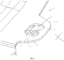
- FIG. 1 an embodiment of a Vorfixier raised is shown on a body component 1, wherein the body component 1 is brought to a vehicle frame part 6 for conditioning.
- the extending in the longitudinal direction L side edge 2 of the body part 1 and the frame edge 5 of the vehicle frame part 6 are parallel and substantially flush.
- the tab 4 is bent in the embodiment shown in the vertical direction with respect to the plane parallel to the surface of the body component 1 and the protruding portion 3 by an angle ⁇ of 30 °. The bend is done by, for example achieved pneumatic punching tools or other bending devices.
- the tab 4 is 10 mm long in the transverse direction Q in the exemplary embodiment shown, and 5 mm in the longitudinal direction L. In the vertical direction, it has a thickness of 1.6 mm. Your side edge 2 facing free end is rounded.
- Corresponding protruding portions 3 with tabs 4 spaced longitudinally are repeatedly arranged on the body component 1 in order to distribute the load over a plurality of tabs 4.
- corresponding Vorfixier wornen along an edge perpendicular to the side edge 2 edge can be provided.
- the invention is not limited in its execution to the above-mentioned preferred embodiments. Rather, a number of variants is conceivable, which makes use of the illustrated solution even with fundamentally different types of use. For example, several tabs can be arranged side by side.
Landscapes
- Engineering & Computer Science (AREA)
- Mechanical Engineering (AREA)
- Manufacturing & Machinery (AREA)
- Chemical & Material Sciences (AREA)
- Combustion & Propulsion (AREA)
- Transportation (AREA)
- Physics & Mathematics (AREA)
- Optics & Photonics (AREA)
- Body Structure For Vehicles (AREA)
- Connection Of Plates (AREA)
- Insertion Pins And Rivets (AREA)
Description
- Die Erfindung betrifft ein Karosseriebauteil mit einer an seiner Seitenkante ausgebildeten Vorfixiereinrichtung, über die das Karosseriebauteil an einem Fahrzeugrahmen vorfixierbar ist. Die
US 5,199,156 offenbart ein Karosseriebauteil nach dem Oberbegriff des Anspruchs 1. - Im Automobilbau ist bekannt, Karosseriebauteile an Fahrzeugrahmenteilen, beispielsweise der Bodengruppe, in einen Zwischenzustand der Rohkarosserie vorzufixieren. Hierzu werden sogenannte Tabbinglaschen verwendet, welche die Zusammenbauten vor der Schweißstation an dem bis dahin aufgebauten Zustand der Rohkarosserie vorpositionieren und fixieren. Wenn die vorzufixierenden Bauteile in die gewünschte Anlageposition gebracht wurden, werden sie durch die Tabbinglaschen in einer separaten Station aneinander befestigt, indem die an dem einen Bauteil ausgebildeten Laschen um 60 - 180° und um die Kante des angrenzenden Bauteils gebogen werden.
- Die Tabbinglaschen umgreifen dabei die Kante und halten die Bauteile in Position. Da Tabbinglaschen an allen Seiten vorgesehen werden können, kann eine Relativbewegung der Bauteile zueinander in alle Richtungen verhindert werden.
- Auch sind Varianten der Tabbinglasche mit einem "S"-Schlag möglich. "S-Schlag" bedeutet, dass die Tabbinglasche zweifach gebogen wird, um durch eine Öffnung an dem zu fixierenden Bauteil geführt (erste Biegung) und anschließend an das Bauteil zu Anlage gebracht zu werden (zweite Biegung in Gegenrichtung). Bei dieser Variante sind vorgelagerte Biegeoperationen von 90° bzw. -90° erforderlich.
- Grundsätzlich ist nachteilig, dass bei höher und höchstfesten Materialien, vor allem warmumgeformten Stählen, sowie bei hohen Blechstärken größer 1,2mm die Gefahr besteht, dass die Tabbinglaschen beim Biegen brechen und eine Fixierung und Positionierung der Zusammenbauten am Rohbau nicht mehr möglich ist.
- Die Problematik besteht auch bei warmumgeformten Bauteilen, deren Tabbinglaschen als ungehärtete Bereiche ausgeführt sind.
- Der Erfindung liegt deshalb die Aufgabe zugrunde, ein Karosseriebauteil bereit zu stellen, das eine Vorfixiereinrichtung mit Tabbinglaschen aufweist, die weniger stark belastet werden.
- Diese Aufgabe wird durch die Merkmalskombination gemäß Patentanspruch 1 gelöst.
- Erfindungsgemäß wird ein Karosseriebauteil mit einer sich in einer Längsrichtung erstreckenden Seitenkante vorgeschlagen, an der mindestens eine Vorfixiereinrichtung ausgebildet ist, die einen gegenüber der Seitenkante in einer Querrichtung vorstehenden Abschnitt aufweist, an dem eine zur Seitenkante weisende Lasche (Tabbinglasche) ausgebildet ist. Die Lasche ist in einer Vertikalrichtung senkrecht zur Längsrichtung biegbar und ausgebildet, eine Rahmenkante eines Fahrzeugrahmenteils vorfixierend hintergreifen zu können.
- Durch die Anordnung der Lasche in dem vorstehenden Abschnitt und die rückwärtsgerichtete Erstreckung zur Seitenkante des Karosseriebauteils sowie der Rahmenkante des Fahrzeugrahmenteils wird erreicht, dass der nötige Biegewinkel deutliche reduziert wird. Es reicht bereits aus, die Lasche nur so weit zu verbiegen, dass diese bei einer Relativbewegung des Karosseriebauteils gegenüber dem Fahrzeugrahmenteil einen Anschlag bildet.
- In einer vorteilhaften Ausführung ist vorgesehen, dass die Lasche zumindest abschnittsweise in Vertikalrichtung gegenüber einer Ebene parallel zu einer Oberfläche des Karosseriebauteils und des vorstehenden Abschnitts um einen Winkel von 15 - 40°, vorzugsweise 15 - 30° gebogen ist. Die gewinkelte Ausbildung lässt die Lasche schräg in Richtung der Seitenkanten des Karosseriebauteils und Fahrzeugrahmenteils zulaufen, wobei die Lasche bei einer Relativbewegung der beiden Bauteile an die Rahmenkante des Fahrzeugrahmenteils zur Anlage kommt und eine relative Weiterbewegung verhindert. Die geringe Biegung in nur eine Richtung reicht demzufolge aus, um den Hintergriff bei der Relativbewegung sicherzustellen und den Anschlag zu bilden.
- In einer günstigen Ausführungsform der Erfindung ist der vorstehende Abschnitt ringförmig und weist eine Öffnung auf, in die die Lasche hineinragt. Die Lasche wird vorzugsweise einteilig an dem ringförmigen vorstehenden Abschnitt ausgebildet. Auch der vorstehende Abschnitt ist vorzugsweise einteilig an dem Karosseriebauteil ausgebildet.
- Zur Gewährleistung einer ausreichenden Stabilität wird in einer Ausführung vorgesehen, dass die Lasche in Querrichtung eine Breite aufweist, die 20 - 70% einer Breite des vorstehenden Abschnitts in Querrichtung entspricht.
- Die Laschendicke in Vertikalrichtung ist vorzugsweise größer oder gleich 1,2 mm.
- Bezüglich der Form der Lasche ist ferner günstig, ihr freies Ende abgerundet auszubilden. Das freie Ende ist in Richtung der Seitenkante des Karosseriebauteils und Fahrzeugrahmenteils gerichtet. Bei einer Relativbewegung können sich die Lasche und die Bauteile berühren. Eine gerundete Form ist deshalb bevorzugt.
- Ferner ist in einer Ausführungsvariante vorgesehen, dass ein Abstand in Querrichtung zwischen der Seitenkante und dem freien Ende der Lasche mindestens 2 mm beträgt. Dieser Abstand ermöglicht ein Anlegen des Karosseriebauteils und Fahrzeugrahmenteils ohne ständige Vorfixierung. Vielmehr greift die Lasche nur hinter die Rahmenkante des Fahrzeugrahmenteils, wenn sich die Bauteile relativ zueinander bewegen, beispielsweise beim Transport zur Schweißstation. Für die sonst lose Vorfixierung wird ein Spiel der Bauteile zueinander gewährleistet.
- Auch ist vorteilhaft, wenn die Lasche aus demselben Material wie das Karosseriebauteil gebildet ist. Da vorzugsweise warm- oder kaltumgeformte Stähle für das Karosseriebauteil eingesetzt werden, erhält die Lasche eine ausreichende Festigkeit.
- Die Erfindung umfasst auch das Verfahren zur beweglichen Vorfixierung des vorstehend beschriebenen Karosseriebauteils an dem Fahrzeugrahmenteil, wobei das Karosseriebauteil an den Fahrzeugrahmenteil angelegt wird, so dass die Seitenkante des Karosseriebauteils parallel zur Rahmenkante verläuft und der vorstehende Abschnitt von der Rahmenkante in Querrichtung beabstandet ist, wobei die Lasche in Richtung der Rahmenkante weist und zumindest abschnittsweise in Vertikalrichtung gegenüber einer Ebene parallel zu einer Oberfläche des Karosseriebauteils und des vorstehenden Abschnitts um einen Winkel von 15 - 40° gebogen ist, so dass die Lasche bei einer Relativbewegung zwischen dem Karosseriebauteil und dem Fahrzeugrahmen in Querrichtung die Rahmenkante hintergreift.
- Bei dem Verfahren wird vorzugsweise ferner vorgesehen, dass das freie Ende der Lasche beim Anlegen des Karosseriebauteils an den Fahrzeugrahmen von dem Fahrzeugrahmen beabstandet ist. Dieser Abstand ermöglicht das oben beschriebene Anlegen des Karosseriebauteils und Fahrzeugrahmenteils ohne ständige Vorfixierung und den Hintergriff der Lasche hinter die Seitenkante des Fahrzeugrahmenteils nur in dem Fall, wenn sich die Bauteile relativ zueinander bewegen.
- Andere vorteilhafte Weiterbildungen der Erfindung sind in den Unteransprüchen gekennzeichnet bzw. werden nachstehend zusammen mit der Beschreibung der bevorzugten Ausführung der Erfindung anhand der Figur näher dargestellt.
- Fig. 1
- zeigt eine perspektivische Ansicht einer Vorfixiereinrichtung an einem Karosseriebauteil.
- In
Figur 1 ist ein Ausführungsbeispiel einer Vorfixiereinrichtung an einem Karosseriebauteil 1 gezeigt, wobei das Karosseriebauteil 1 an einem Fahrzeugrahmenteil 6 zur Anlage gebracht ist. Die sich in Längsrichtung L erstreckende Seitenkante 2 des Karosserieteils 1 und die Rahmenkante 5 des Fahrzeugrahmenteils 6 verlaufen parallel und im Wesentlichen bündig. - An dem Karosseriebauteil 1 erstreckt sich einteilig in Querrichtung Q ein ringförmiger über die Seitenkante 2 vorstehender Abschnitt 3, an dem die zur Seitenkante 2 weisende Lasche 4 ausgebildet ist. In dem vorstehenden Abschnitt 3 ist hierzu eine Öffnung 7 vorgesehen. Die Lasche 4 ist in der gezeigten Ausführung in Vertikalrichtung gegenüber der Ebene parallel zur Oberfläche des Karosseriebauteils 1 und des vorstehenden Abschnitts 3 um einen Winkel α von 30° gebogen. Die Biegung wird beispielsweise durch pneumatische Stempelwerkzeuge oder andere Biegevorrichtungen erzielt. Die Lasche 4 ist in Querrichtung Q in der gezeigten beispielhaften Ausführung 10mm lang und in Längsrichtung L 5 mm breit. In Vertikalrichtung weist sie eine Dicke von 1,6 mm auf. Ihr zur Seitenkante 2 weisendes freies Ende ist abgerundet.
- In Querrichtung Q ist zwischen der Seitenkante 2 und dem freien Ende der Lasche 4 ein Abstand vorgesehen. Die Vorfixiereinrichtung fixiert deshalb in diesem Zustand nicht arretierend, sondern bietet die Möglichkeit des Hintergriffs der Lasche 4 hinter die Rahmenkante 5 bei einer Relativbewegung des Karosseriebauteils 1 gegenüber dem Fahrzeugrahmenteil 6 in Querrichtung.
- An dem Karosseriebauteil 1 sind entsprechende vorstehende Abschnitte 3 mit Laschen 4 in Längsrichtung beabstandet wiederholt angeordnet, um die Last auf mehrere Laschen 4 zu verteilen. Zusätzlich können auch entsprechende Vorfixiereinrichtungen entlang einer senkrecht zur Seitenkante 2 verlaufenden Kante vorgesehen werden.
- Die Erfindung beschränkt sich in ihrer Ausführung nicht auf die vorstehend angegebenen bevorzugten Ausführungsbeispiele. Vielmehr ist eine Anzahl von Varianten denkbar, welche von der dargestellten Lösung auch bei grundsätzlich anders gearteten Ausführungen Gebrauch macht. Beispielsweise können auch mehrere Laschen nebeneinander angeordnet werden.
Claims (10)
- Karosseriebauteil mit einer sich in einer Längsrichtung (L) erstreckenden Seitenkante (2), an der mindestens eine Vorfixiereinrichtung ausgebildet ist, dadurch gekennzeichnet, dass die Vorfixiereinrichtung einen gegenüber der Seitenkante (2) in einer Querrichtung (Q) vorstehenden Abschnitt (3) aufweist, an dem eine zur Seitenkante (2) weisende Lasche (4) ausgebildet ist, die in einer Vertikalrichtung senkrecht zur Längsrichtung (L) biegbar und ausgebildet ist, eine Rahmenkante (5) eines Fahrzeugrahmenteils (6) vorfixierend hintergreifen zu können.
- Karosseriebauteil nach Anspruch 1, dadurch gekennzeichnet, dass die Lasche (4) zumindest abschnittsweise in Vertikalrichtung gegenüber einer Ebene parallel zu einer Oberfläche des Karosseriebauteils (1) und des vorstehenden Abschnitts (3) um einen Winkel (α) von 15 - 40° gebogen ist.
- Karosseriebauteil nach Anspruch 1 oder 2, dadurch gekennzeichnet, dass der vorstehende Abschnitt eine Öffnung (7) aufweist, in die die Lasche (4) hineinragt.
- Karosseriebauteil nach zumindest einem der vorigen Ansprüche, dadurch gekennzeichnet, dass die Lasche (4) in Querrichtung (Q) eine Breite aufweist, die 20 - 70% einer Breite des vorstehenden Abschnitts (3) in Querrichtung (Q) entspricht.
- Karosseriebauteil nach zumindest einem der vorigen Ansprüche, dadurch gekennzeichnet, dass der vorstehende Abschnitt (3) und die Lasche (4) einteilig an dem Karosseriebauteil (1) ausgebildet sind.
- Karosseriebauteil nach zumindest einem der vorigen Ansprüche, dadurch gekennzeichnet, dass ein freies Ende der Lasche (4) abgerundet ist.
- Karosseriebauteil nach zumindest einem der vorigen Ansprüche, dadurch gekennzeichnet, dass ein Abstand in Querrichtung (Q) zwischen der Seitenkante (2) und einem/dem freien Ende der Lasche (4) mindestens 2 mm beträgt.
- Karosseriebauteil nach zumindest einem der vorigen Ansprüche, dadurch gekennzeichnet, dass die Lasche (4) aus demselben Material wie das Karosseriebauteil (1) gebildet ist.
- Verfahren zur beweglichen Vorfixierung des Karosseriebauteils (1) nach zumindest einem der vorigen Ansprüche an dem Fahrzeugrahmenteil (6), wobei das Karosseriebauteil (1) an den Fahrzeugrahmenteil (6) angelegt wird, so dass die Seitenkante (2) des Karosseriebauteils (1) parallel zur Rahmenkante (5) verläuft und der vorstehende Abschnitt (3) von der Rahmenkante (5) in Querrichtung beabstandet ist, wobei die Lasche (4) in Richtung der Rahmenkante (5) weist und zumindest abschnittsweise in Vertikalrichtung gegenüber einer Ebene parallel zu einer Oberfläche des Karosseriebauteils (1) und des vorstehenden Abschnitts (3) um einen Winkel (α) von 15 - 40° gebogen ist, so dass die Lasche (4) bei einer Relativbewegung zwischen dem Karosseriebauteil (1) und dem Fahrzeugrahmenteil (6) in Querrichtung (Q) die Rahmenkante (5) hintergreift.
- Verfahren nach dem vorigen Anspruch, dadurch gekennzeichnet, dass ein freies Ende der Lasche (4) beim Anlegen des Karosseriebauteils (1) an den Fahrzeugrahmenteil (6) von dem Fahrzeugrahmenteil beabstandet ist.
Applications Claiming Priority (2)
| Application Number | Priority Date | Filing Date | Title |
|---|---|---|---|
| DE102015218817.5A DE102015218817A1 (de) | 2015-09-30 | 2015-09-30 | Karosseriebauteil mit Tabbinglasche zur Vorfixierung |
| PCT/EP2016/071432 WO2017055062A1 (de) | 2015-09-30 | 2016-09-12 | Karosseriebauteil mit tabbinglasche zur vorfixierung |
Publications (2)
| Publication Number | Publication Date |
|---|---|
| EP3356079A1 EP3356079A1 (de) | 2018-08-08 |
| EP3356079B1 true EP3356079B1 (de) | 2019-09-04 |
Family
ID=56943499
Family Applications (1)
| Application Number | Title | Priority Date | Filing Date |
|---|---|---|---|
| EP16766904.3A Active EP3356079B1 (de) | 2015-09-30 | 2016-09-12 | Karosseriebauteil mit tabbinglasche zur vorfixierung |
Country Status (5)
| Country | Link |
|---|---|
| US (1) | US10549390B2 (de) |
| EP (1) | EP3356079B1 (de) |
| CN (1) | CN107683188B (de) |
| DE (1) | DE102015218817A1 (de) |
| WO (1) | WO2017055062A1 (de) |
Families Citing this family (2)
| Publication number | Priority date | Publication date | Assignee | Title |
|---|---|---|---|---|
| DE102018213520B4 (de) * | 2018-08-10 | 2026-02-26 | Bayerische Motoren Werke Aktiengesellschaft | Kraftfahrzeug |
| CN117922731A (zh) * | 2024-02-26 | 2024-04-26 | 上海恩井汽车科技有限公司 | 预定位装置及空气扰流装置 |
Family Cites Families (36)
| Publication number | Priority date | Publication date | Assignee | Title |
|---|---|---|---|---|
| US3702386A (en) * | 1971-04-06 | 1972-11-07 | Amana Refrigeration Inc | Mechanical coupling arrangement |
| FR2552946B1 (fr) * | 1983-09-29 | 1985-12-27 | Amp France | Connecteur electrique destine a s'accoupler avec trois languettes et borne pour ce connecteur |
| US4564111A (en) * | 1983-12-29 | 1986-01-14 | The Mead Corporation | Post-panel connection for sheet metal furniture |
| DE3482103D1 (de) * | 1984-01-04 | 1990-06-07 | Litton Uk Ltd | Aufstellungs- und haltevorrichtung. |
| US4817861A (en) * | 1987-02-24 | 1989-04-04 | Henrikson Gregory A | File storage carton |
| US5213256A (en) * | 1987-03-18 | 1993-05-25 | Amoco Corporation | Container assembly having a removable insert/divider |
| JPH01147930U (de) * | 1988-04-04 | 1989-10-13 | ||
| US4919785A (en) * | 1988-04-28 | 1990-04-24 | Kraft General Foods, Inc. | Microwave carton |
| US4911685A (en) * | 1988-10-26 | 1990-03-27 | Hucks Billy R | Coin package |
| US5199156A (en) * | 1990-10-09 | 1993-04-06 | Rossi Christiano G | Method for assembling a vehicle using an automatic toy tab system |
| US5207375A (en) * | 1990-11-20 | 1993-05-04 | Inland Container Corporation | Container made from one-piece blank |
| US5249082A (en) * | 1991-05-08 | 1993-09-28 | Eastman Kodak Company | Exact constraint arrangement for and methods of mounting an element such as a lens |
| US5328080A (en) * | 1993-02-08 | 1994-07-12 | The Mead Corporation | Panel interlocking arrangement for wraparound carrier |
| WO1998012437A1 (en) | 1996-09-20 | 1998-03-26 | Caterpillar Inc. | Apparatus and method for securing a first fabrication element to a second fabrication element during a welding operation |
| FR2823805B1 (fr) * | 2001-04-19 | 2004-03-12 | Plastic Omnium Cie | Ensemble de deux pieces de carrosserie a reunir bord a bord et une piece de carrosserie appartenant a un tel ensemble |
| FR2823804B1 (fr) * | 2001-04-19 | 2004-03-26 | Plastic Omnium Cie | Ensemble de deux pieces de carrosserie a reunir bord a bord et piece de carosserie appartenant a un tel ensemble |
| US6499783B1 (en) * | 2001-10-09 | 2002-12-31 | Delores J. Husted | Convertible flatbed utility stock trailer |
| US7207617B2 (en) * | 2005-03-14 | 2007-04-24 | Nissan Technical Center North America, Inc. | Vehicle body structure |
| US7390052B2 (en) * | 2005-07-11 | 2008-06-24 | Fleetwood Enterprises, Inc. | Light weight chassis and hull |
| US7488032B2 (en) * | 2006-09-18 | 2009-02-10 | Nissan Technical Center North America, Inc. | Attachment joint for plastic over-fender to plastic fascia |
| US8042852B2 (en) * | 2007-12-21 | 2011-10-25 | Honda Motor Co., Ltd. | Method for mounting flanged plastic garnish with support post, for painting on-line |
| US7726717B2 (en) * | 2007-12-21 | 2010-06-01 | Honda Motor Co., Ltd. | Method for mounting plastic garnish for painting on-line |
| US7770955B2 (en) * | 2008-03-14 | 2010-08-10 | Gm Global Technology Operations, Inc. | Automotive closure panel assembly |
| CN201366994Y (zh) * | 2009-01-21 | 2009-12-23 | 宁波信泰机械有限公司 | 卡扣及使用该卡扣将亮条安装在注塑包边上的连接结构 |
| DE102009048168A1 (de) * | 2009-10-02 | 2010-05-20 | Daimler Ag | Verfahren und Zwischenelement zum Herstellen einer Verbindung von zwei Karosseriebauteilen eines Kraftwagens |
| US8087721B2 (en) * | 2009-08-17 | 2012-01-03 | Honda Motor Co., Ltd. | Reinforcement bracket and related methods for on-line painting |
| US8443923B2 (en) * | 2011-03-17 | 2013-05-21 | Cnh America Llc | Vibration isolator device |
| US8490358B2 (en) * | 2011-03-31 | 2013-07-23 | Ned C. Bowers | Interlocking flange and fastening system and method for securing together two panels |
| US20120297584A1 (en) * | 2011-05-24 | 2012-11-29 | Chung Chwan Enterprise Co., Ltd. | Zipper head structure |
| CN102929018B (zh) * | 2012-11-20 | 2015-04-01 | 深圳市华星光电技术有限公司 | 一种面板与框架的连接结构及其卡持件 |
| DE102013215823B4 (de) | 2013-08-09 | 2021-08-05 | Bayerische Motoren Werke Aktiengesellschaft | Clipsbefestigungsvorrichtung, insbesondere für Kraftfahrzeuge |
| TWI681599B (zh) * | 2014-04-17 | 2020-01-01 | 法商內數位Ce專利控股公司 | 至少一電子配件之電氣接地配件及其電子板和電子裝置 |
| CN203926259U (zh) * | 2014-06-04 | 2014-11-05 | 北京汽车研究总院有限公司 | 一种用于车门内饰板与钣金安装的金属卡子 |
| EP2985107B1 (de) * | 2014-08-15 | 2017-03-01 | Volvo Car Corporation | Ein Strukturbauteil und ein Herstellungsverfahren von diesem Bauteil |
| CN204368288U (zh) * | 2014-12-19 | 2015-06-03 | 北京汽车研究总院有限公司 | 一种卡扣座及汽车 |
| US10202149B1 (en) * | 2017-08-11 | 2019-02-12 | Super ATV, LLC | ATV/UTV skid plate assembly |
-
2015
- 2015-09-30 DE DE102015218817.5A patent/DE102015218817A1/de not_active Withdrawn
-
2016
- 2016-09-12 WO PCT/EP2016/071432 patent/WO2017055062A1/de not_active Ceased
- 2016-09-12 CN CN201680037478.9A patent/CN107683188B/zh active Active
- 2016-09-12 EP EP16766904.3A patent/EP3356079B1/de active Active
-
2018
- 2018-03-27 US US15/937,532 patent/US10549390B2/en active Active
Non-Patent Citations (1)
| Title |
|---|
| None * |
Also Published As
| Publication number | Publication date |
|---|---|
| US10549390B2 (en) | 2020-02-04 |
| US20180214994A1 (en) | 2018-08-02 |
| WO2017055062A1 (de) | 2017-04-06 |
| EP3356079A1 (de) | 2018-08-08 |
| DE102015218817A1 (de) | 2017-03-30 |
| CN107683188A (zh) | 2018-02-09 |
| CN107683188B (zh) | 2019-11-12 |
Similar Documents
| Publication | Publication Date | Title |
|---|---|---|
| DE102017123325B4 (de) | Stoßfängerquerträger | |
| DE3500400C2 (de) | ||
| DE102019124074A1 (de) | Instrumententafelträger für ein Kraftfahrzeug | |
| EP3452734A1 (de) | Clip zum befestigen eines ersten elements an einem zweiten element | |
| DE3918802A1 (de) | Schmutzfaengerbefestigung | |
| WO2017016651A1 (de) | Vorrichtung zum halten eines bauteils | |
| WO2016113136A1 (de) | Hohlprofil mit sicken | |
| WO2016026745A1 (de) | Aggregatlager-anordnung | |
| WO2017055062A1 (de) | Karosseriebauteil mit tabbinglasche zur vorfixierung | |
| DE112015000052B4 (de) | Fahrzeugkarosseriefrontstruktur | |
| EP2429734A1 (de) | Schubkasten mit zwei seitenwänden und einer rückwand | |
| DE2926965C2 (de) | Schnellösende Befestigungsvorrichtung | |
| DE102014223054B4 (de) | Fahrzeugkarosserie für ein zweispuriges Fahrzeug | |
| EP3658415B1 (de) | Vorrichtung zur aufnahme eines gegenstands in einem kraftfahrzeug | |
| DE102012021308B4 (de) | Verbindungssystem | |
| DE102009057833A1 (de) | Vorrichtung zur Halterung eines Funktionsteils, insbesondere eines Dachhaltegriffs, in einem Fahrzeug | |
| DE2353418A1 (de) | Fassungsvorrichtung | |
| DE69308598T2 (de) | Filterelement | |
| DE102022120617B4 (de) | Stoßfängeranordnung mit endseitiger Verlängerung | |
| DE102014017786B4 (de) | Befestigungsblech mit einem Fixierhaken sowie Gurtaufroller und Fahrzeugkarosserie mit einem Befestigungsblech | |
| DE2413707A1 (de) | Verbindungselement fuer hohlprofilteile, insbesondere eckverbinder | |
| DE3047133A1 (de) | Vorrichtung zur lagesichernden verbindung zweier bauteile | |
| EP1078820B1 (de) | Clipsverbindung | |
| DE102016221145A1 (de) | Bauteilverbindung | |
| DE102019212846B4 (de) | Anbindungssystem für Bauteile |
Legal Events
| Date | Code | Title | Description |
|---|---|---|---|
| STAA | Information on the status of an ep patent application or granted ep patent |
Free format text: STATUS: THE INTERNATIONAL PUBLICATION HAS BEEN MADE |
|
| PUAI | Public reference made under article 153(3) epc to a published international application that has entered the european phase |
Free format text: ORIGINAL CODE: 0009012 |
|
| STAA | Information on the status of an ep patent application or granted ep patent |
Free format text: STATUS: REQUEST FOR EXAMINATION WAS MADE |
|
| 17P | Request for examination filed |
Effective date: 20180207 |
|
| AK | Designated contracting states |
Kind code of ref document: A1 Designated state(s): AL AT BE BG CH CY CZ DE DK EE ES FI FR GB GR HR HU IE IS IT LI LT LU LV MC MK MT NL NO PL PT RO RS SE SI SK SM TR |
|
| AX | Request for extension of the european patent |
Extension state: BA ME |
|
| DAV | Request for validation of the european patent (deleted) | ||
| DAX | Request for extension of the european patent (deleted) | ||
| GRAP | Despatch of communication of intention to grant a patent |
Free format text: ORIGINAL CODE: EPIDOSNIGR1 |
|
| STAA | Information on the status of an ep patent application or granted ep patent |
Free format text: STATUS: GRANT OF PATENT IS INTENDED |
|
| INTG | Intention to grant announced |
Effective date: 20190607 |
|
| GRAS | Grant fee paid |
Free format text: ORIGINAL CODE: EPIDOSNIGR3 |
|
| GRAA | (expected) grant |
Free format text: ORIGINAL CODE: 0009210 |
|
| STAA | Information on the status of an ep patent application or granted ep patent |
Free format text: STATUS: THE PATENT HAS BEEN GRANTED |
|
| AK | Designated contracting states |
Kind code of ref document: B1 Designated state(s): AL AT BE BG CH CY CZ DE DK EE ES FI FR GB GR HR HU IE IS IT LI LT LU LV MC MK MT NL NO PL PT RO RS SE SI SK SM TR |
|
| REG | Reference to a national code |
Ref country code: GB Ref legal event code: FG4D Free format text: NOT ENGLISH |
|
| REG | Reference to a national code |
Ref country code: CH Ref legal event code: EP |
|
| REG | Reference to a national code |
Ref country code: AT Ref legal event code: REF Ref document number: 1174691 Country of ref document: AT Kind code of ref document: T Effective date: 20190915 |
|
| REG | Reference to a national code |
Ref country code: DE Ref legal event code: R096 Ref document number: 502016006455 Country of ref document: DE |
|
| REG | Reference to a national code |
Ref country code: IE Ref legal event code: FG4D Free format text: LANGUAGE OF EP DOCUMENT: GERMAN |
|
| REG | Reference to a national code |
Ref country code: NL Ref legal event code: MP Effective date: 20190904 |
|
| REG | Reference to a national code |
Ref country code: LT Ref legal event code: MG4D |
|
| PG25 | Lapsed in a contracting state [announced via postgrant information from national office to epo] |
Ref country code: NO Free format text: LAPSE BECAUSE OF FAILURE TO SUBMIT A TRANSLATION OF THE DESCRIPTION OR TO PAY THE FEE WITHIN THE PRESCRIBED TIME-LIMIT Effective date: 20191204 Ref country code: FI Free format text: LAPSE BECAUSE OF FAILURE TO SUBMIT A TRANSLATION OF THE DESCRIPTION OR TO PAY THE FEE WITHIN THE PRESCRIBED TIME-LIMIT Effective date: 20190904 Ref country code: LT Free format text: LAPSE BECAUSE OF FAILURE TO SUBMIT A TRANSLATION OF THE DESCRIPTION OR TO PAY THE FEE WITHIN THE PRESCRIBED TIME-LIMIT Effective date: 20190904 Ref country code: HR Free format text: LAPSE BECAUSE OF FAILURE TO SUBMIT A TRANSLATION OF THE DESCRIPTION OR TO PAY THE FEE WITHIN THE PRESCRIBED TIME-LIMIT Effective date: 20190904 Ref country code: SE Free format text: LAPSE BECAUSE OF FAILURE TO SUBMIT A TRANSLATION OF THE DESCRIPTION OR TO PAY THE FEE WITHIN THE PRESCRIBED TIME-LIMIT Effective date: 20190904 Ref country code: BG Free format text: LAPSE BECAUSE OF FAILURE TO SUBMIT A TRANSLATION OF THE DESCRIPTION OR TO PAY THE FEE WITHIN THE PRESCRIBED TIME-LIMIT Effective date: 20191204 |
|
| PG25 | Lapsed in a contracting state [announced via postgrant information from national office to epo] |
Ref country code: GR Free format text: LAPSE BECAUSE OF FAILURE TO SUBMIT A TRANSLATION OF THE DESCRIPTION OR TO PAY THE FEE WITHIN THE PRESCRIBED TIME-LIMIT Effective date: 20191205 Ref country code: AL Free format text: LAPSE BECAUSE OF FAILURE TO SUBMIT A TRANSLATION OF THE DESCRIPTION OR TO PAY THE FEE WITHIN THE PRESCRIBED TIME-LIMIT Effective date: 20190904 Ref country code: LV Free format text: LAPSE BECAUSE OF FAILURE TO SUBMIT A TRANSLATION OF THE DESCRIPTION OR TO PAY THE FEE WITHIN THE PRESCRIBED TIME-LIMIT Effective date: 20190904 Ref country code: RS Free format text: LAPSE BECAUSE OF FAILURE TO SUBMIT A TRANSLATION OF THE DESCRIPTION OR TO PAY THE FEE WITHIN THE PRESCRIBED TIME-LIMIT Effective date: 20190904 Ref country code: ES Free format text: LAPSE BECAUSE OF FAILURE TO SUBMIT A TRANSLATION OF THE DESCRIPTION OR TO PAY THE FEE WITHIN THE PRESCRIBED TIME-LIMIT Effective date: 20190904 |
|
| PG25 | Lapsed in a contracting state [announced via postgrant information from national office to epo] |
Ref country code: RO Free format text: LAPSE BECAUSE OF FAILURE TO SUBMIT A TRANSLATION OF THE DESCRIPTION OR TO PAY THE FEE WITHIN THE PRESCRIBED TIME-LIMIT Effective date: 20190904 Ref country code: PT Free format text: LAPSE BECAUSE OF FAILURE TO SUBMIT A TRANSLATION OF THE DESCRIPTION OR TO PAY THE FEE WITHIN THE PRESCRIBED TIME-LIMIT Effective date: 20200106 Ref country code: PL Free format text: LAPSE BECAUSE OF FAILURE TO SUBMIT A TRANSLATION OF THE DESCRIPTION OR TO PAY THE FEE WITHIN THE PRESCRIBED TIME-LIMIT Effective date: 20190904 Ref country code: NL Free format text: LAPSE BECAUSE OF FAILURE TO SUBMIT A TRANSLATION OF THE DESCRIPTION OR TO PAY THE FEE WITHIN THE PRESCRIBED TIME-LIMIT Effective date: 20190904 Ref country code: EE Free format text: LAPSE BECAUSE OF FAILURE TO SUBMIT A TRANSLATION OF THE DESCRIPTION OR TO PAY THE FEE WITHIN THE PRESCRIBED TIME-LIMIT Effective date: 20190904 |
|
| PG25 | Lapsed in a contracting state [announced via postgrant information from national office to epo] |
Ref country code: CZ Free format text: LAPSE BECAUSE OF FAILURE TO SUBMIT A TRANSLATION OF THE DESCRIPTION OR TO PAY THE FEE WITHIN THE PRESCRIBED TIME-LIMIT Effective date: 20190904 Ref country code: SM Free format text: LAPSE BECAUSE OF FAILURE TO SUBMIT A TRANSLATION OF THE DESCRIPTION OR TO PAY THE FEE WITHIN THE PRESCRIBED TIME-LIMIT Effective date: 20190904 Ref country code: IS Free format text: LAPSE BECAUSE OF FAILURE TO SUBMIT A TRANSLATION OF THE DESCRIPTION OR TO PAY THE FEE WITHIN THE PRESCRIBED TIME-LIMIT Effective date: 20200224 Ref country code: SK Free format text: LAPSE BECAUSE OF FAILURE TO SUBMIT A TRANSLATION OF THE DESCRIPTION OR TO PAY THE FEE WITHIN THE PRESCRIBED TIME-LIMIT Effective date: 20190904 |
|
| REG | Reference to a national code |
Ref country code: CH Ref legal event code: PL |
|
| REG | Reference to a national code |
Ref country code: DE Ref legal event code: R097 Ref document number: 502016006455 Country of ref document: DE |
|
| PLBE | No opposition filed within time limit |
Free format text: ORIGINAL CODE: 0009261 |
|
| STAA | Information on the status of an ep patent application or granted ep patent |
Free format text: STATUS: NO OPPOSITION FILED WITHIN TIME LIMIT |
|
| PG2D | Information on lapse in contracting state deleted |
Ref country code: IS |
|
| PG25 | Lapsed in a contracting state [announced via postgrant information from national office to epo] |
Ref country code: DK Free format text: LAPSE BECAUSE OF FAILURE TO SUBMIT A TRANSLATION OF THE DESCRIPTION OR TO PAY THE FEE WITHIN THE PRESCRIBED TIME-LIMIT Effective date: 20190904 Ref country code: LU Free format text: LAPSE BECAUSE OF NON-PAYMENT OF DUE FEES Effective date: 20190912 Ref country code: IE Free format text: LAPSE BECAUSE OF NON-PAYMENT OF DUE FEES Effective date: 20190912 Ref country code: CH Free format text: LAPSE BECAUSE OF NON-PAYMENT OF DUE FEES Effective date: 20190930 Ref country code: LI Free format text: LAPSE BECAUSE OF NON-PAYMENT OF DUE FEES Effective date: 20190930 Ref country code: IS Free format text: LAPSE BECAUSE OF FAILURE TO SUBMIT A TRANSLATION OF THE DESCRIPTION OR TO PAY THE FEE WITHIN THE PRESCRIBED TIME-LIMIT Effective date: 20200105 |
|
| REG | Reference to a national code |
Ref country code: BE Ref legal event code: MM Effective date: 20190930 |
|
| 26N | No opposition filed |
Effective date: 20200605 |
|
| PG25 | Lapsed in a contracting state [announced via postgrant information from national office to epo] |
Ref country code: MC Free format text: LAPSE BECAUSE OF FAILURE TO SUBMIT A TRANSLATION OF THE DESCRIPTION OR TO PAY THE FEE WITHIN THE PRESCRIBED TIME-LIMIT Effective date: 20190904 Ref country code: SI Free format text: LAPSE BECAUSE OF FAILURE TO SUBMIT A TRANSLATION OF THE DESCRIPTION OR TO PAY THE FEE WITHIN THE PRESCRIBED TIME-LIMIT Effective date: 20190904 Ref country code: BE Free format text: LAPSE BECAUSE OF NON-PAYMENT OF DUE FEES Effective date: 20190930 |
|
| PG25 | Lapsed in a contracting state [announced via postgrant information from national office to epo] |
Ref country code: CY Free format text: LAPSE BECAUSE OF FAILURE TO SUBMIT A TRANSLATION OF THE DESCRIPTION OR TO PAY THE FEE WITHIN THE PRESCRIBED TIME-LIMIT Effective date: 20190904 |
|
| PG25 | Lapsed in a contracting state [announced via postgrant information from national office to epo] |
Ref country code: MT Free format text: LAPSE BECAUSE OF FAILURE TO SUBMIT A TRANSLATION OF THE DESCRIPTION OR TO PAY THE FEE WITHIN THE PRESCRIBED TIME-LIMIT Effective date: 20190904 Ref country code: HU Free format text: LAPSE BECAUSE OF FAILURE TO SUBMIT A TRANSLATION OF THE DESCRIPTION OR TO PAY THE FEE WITHIN THE PRESCRIBED TIME-LIMIT; INVALID AB INITIO Effective date: 20160912 |
|
| PG25 | Lapsed in a contracting state [announced via postgrant information from national office to epo] |
Ref country code: TR Free format text: LAPSE BECAUSE OF FAILURE TO SUBMIT A TRANSLATION OF THE DESCRIPTION OR TO PAY THE FEE WITHIN THE PRESCRIBED TIME-LIMIT Effective date: 20190904 |
|
| PG25 | Lapsed in a contracting state [announced via postgrant information from national office to epo] |
Ref country code: MK Free format text: LAPSE BECAUSE OF FAILURE TO SUBMIT A TRANSLATION OF THE DESCRIPTION OR TO PAY THE FEE WITHIN THE PRESCRIBED TIME-LIMIT Effective date: 20190904 |
|
| REG | Reference to a national code |
Ref country code: AT Ref legal event code: MM01 Ref document number: 1174691 Country of ref document: AT Kind code of ref document: T Effective date: 20210912 |
|
| PG25 | Lapsed in a contracting state [announced via postgrant information from national office to epo] |
Ref country code: AT Free format text: LAPSE BECAUSE OF NON-PAYMENT OF DUE FEES Effective date: 20210912 |
|
| P01 | Opt-out of the competence of the unified patent court (upc) registered |
Effective date: 20230503 |
|
| PGFP | Annual fee paid to national office [announced via postgrant information from national office to epo] |
Ref country code: DE Payment date: 20250909 Year of fee payment: 10 |
|
| PGFP | Annual fee paid to national office [announced via postgrant information from national office to epo] |
Ref country code: GB Payment date: 20250923 Year of fee payment: 10 |
|
| PGFP | Annual fee paid to national office [announced via postgrant information from national office to epo] |
Ref country code: FR Payment date: 20250926 Year of fee payment: 10 |
|
| PGFP | Annual fee paid to national office [announced via postgrant information from national office to epo] |
Ref country code: IT Payment date: 20250930 Year of fee payment: 10 |