EP3355949B1 - Verfahren zur beschichtung und kaschierung von endoluminalprothesen mittels elektrospinning - Google Patents
Verfahren zur beschichtung und kaschierung von endoluminalprothesen mittels elektrospinning Download PDFInfo
- Publication number
- EP3355949B1 EP3355949B1 EP16791670.9A EP16791670A EP3355949B1 EP 3355949 B1 EP3355949 B1 EP 3355949B1 EP 16791670 A EP16791670 A EP 16791670A EP 3355949 B1 EP3355949 B1 EP 3355949B1
- Authority
- EP
- European Patent Office
- Prior art keywords
- fibers
- target
- applicator
- solvent
- release agent
- Prior art date
- Legal status (The legal status is an assumption and is not a legal conclusion. Google has not performed a legal analysis and makes no representation as to the accuracy of the status listed.)
- Active
Links
Images


Classifications
-
- D—TEXTILES; PAPER
- D01—NATURAL OR MAN-MADE THREADS OR FIBRES; SPINNING
- D01D—MECHANICAL METHODS OR APPARATUS IN THE MANUFACTURE OF ARTIFICIAL FILAMENTS, THREADS, FIBRES, BRISTLES OR RIBBONS
- D01D5/00—Formation of filaments, threads, or the like
- D01D5/0007—Electro-spinning
- D01D5/0061—Electro-spinning characterised by the electro-spinning apparatus
- D01D5/0076—Electro-spinning characterised by the electro-spinning apparatus characterised by the collecting device, e.g. drum, wheel, endless belt, plate or grid
- D01D5/0084—Coating by electro-spinning, i.e. the electro-spun fibres are not removed from the collecting device but remain integral with it, e.g. coating of prostheses
-
- A—HUMAN NECESSITIES
- A61—MEDICAL OR VETERINARY SCIENCE; HYGIENE
- A61L—METHODS OR APPARATUS FOR STERILISING MATERIALS OR OBJECTS IN GENERAL; DISINFECTION, STERILISATION OR DEODORISATION OF AIR; CHEMICAL ASPECTS OF BANDAGES, DRESSINGS, ABSORBENT PADS OR SURGICAL ARTICLES; MATERIALS FOR BANDAGES, DRESSINGS, ABSORBENT PADS OR SURGICAL ARTICLES
- A61L27/00—Materials for grafts or prostheses or for coating grafts or prostheses
- A61L27/14—Macromolecular materials
- A61L27/18—Macromolecular materials obtained otherwise than by reactions only involving carbon-to-carbon unsaturated bonds
-
- A—HUMAN NECESSITIES
- A61—MEDICAL OR VETERINARY SCIENCE; HYGIENE
- A61L—METHODS OR APPARATUS FOR STERILISING MATERIALS OR OBJECTS IN GENERAL; DISINFECTION, STERILISATION OR DEODORISATION OF AIR; CHEMICAL ASPECTS OF BANDAGES, DRESSINGS, ABSORBENT PADS OR SURGICAL ARTICLES; MATERIALS FOR BANDAGES, DRESSINGS, ABSORBENT PADS OR SURGICAL ARTICLES
- A61L27/00—Materials for grafts or prostheses or for coating grafts or prostheses
- A61L27/28—Materials for coating prostheses
- A61L27/34—Macromolecular materials
-
- A—HUMAN NECESSITIES
- A61—MEDICAL OR VETERINARY SCIENCE; HYGIENE
- A61L—METHODS OR APPARATUS FOR STERILISING MATERIALS OR OBJECTS IN GENERAL; DISINFECTION, STERILISATION OR DEODORISATION OF AIR; CHEMICAL ASPECTS OF BANDAGES, DRESSINGS, ABSORBENT PADS OR SURGICAL ARTICLES; MATERIALS FOR BANDAGES, DRESSINGS, ABSORBENT PADS OR SURGICAL ARTICLES
- A61L31/00—Materials for other surgical articles, e.g. stents, stent-grafts, shunts, surgical drapes, guide wires, materials for adhesion prevention, occluding devices, surgical gloves, tissue fixation devices
- A61L31/08—Materials for coatings
- A61L31/10—Macromolecular materials
-
- D—TEXTILES; PAPER
- D01—NATURAL OR MAN-MADE THREADS OR FIBRES; SPINNING
- D01D—MECHANICAL METHODS OR APPARATUS IN THE MANUFACTURE OF ARTIFICIAL FILAMENTS, THREADS, FIBRES, BRISTLES OR RIBBONS
- D01D5/00—Formation of filaments, threads, or the like
- D01D5/0007—Electro-spinning
- D01D5/0015—Electro-spinning characterised by the initial state of the material
- D01D5/003—Electro-spinning characterised by the initial state of the material the material being a polymer solution or dispersion
- D01D5/0046—Electro-spinning characterised by the initial state of the material the material being a polymer solution or dispersion the fibre formed by coagulation, i.e. wet electro-spinning
-
- D—TEXTILES; PAPER
- D01—NATURAL OR MAN-MADE THREADS OR FIBRES; SPINNING
- D01D—MECHANICAL METHODS OR APPARATUS IN THE MANUFACTURE OF ARTIFICIAL FILAMENTS, THREADS, FIBRES, BRISTLES OR RIBBONS
- D01D5/00—Formation of filaments, threads, or the like
- D01D5/0007—Electro-spinning
- D01D5/0061—Electro-spinning characterised by the electro-spinning apparatus
- D01D5/0069—Electro-spinning characterised by the electro-spinning apparatus characterised by the spinning section, e.g. capillary tube, protrusion or pin
-
- D—TEXTILES; PAPER
- D01—NATURAL OR MAN-MADE THREADS OR FIBRES; SPINNING
- D01D—MECHANICAL METHODS OR APPARATUS IN THE MANUFACTURE OF ARTIFICIAL FILAMENTS, THREADS, FIBRES, BRISTLES OR RIBBONS
- D01D5/00—Formation of filaments, threads, or the like
- D01D5/0007—Electro-spinning
- D01D5/0061—Electro-spinning characterised by the electro-spinning apparatus
- D01D5/0092—Electro-spinning characterised by the electro-spinning apparatus characterised by the electrical field, e.g. combined with a magnetic fields, using biased or alternating fields
-
- D—TEXTILES; PAPER
- D04—BRAIDING; LACE-MAKING; KNITTING; TRIMMINGS; NON-WOVEN FABRICS
- D04H—MAKING TEXTILE FABRICS, e.g. FROM FIBRES OR FILAMENTARY MATERIAL; FABRICS MADE BY SUCH PROCESSES OR APPARATUS, e.g. FELTS, NON-WOVEN FABRICS; COTTON-WOOL; WADDING ; NON-WOVEN FABRICS FROM STAPLE FIBRES, FILAMENTS OR YARNS, BONDED WITH AT LEAST ONE WEB-LIKE MATERIAL DURING THEIR CONSOLIDATION
- D04H1/00—Non-woven fabrics formed wholly or mainly of staple fibres or like relatively short fibres
- D04H1/70—Non-woven fabrics formed wholly or mainly of staple fibres or like relatively short fibres characterised by the method of forming fleeces or layers, e.g. reorientation of fibres
- D04H1/72—Non-woven fabrics formed wholly or mainly of staple fibres or like relatively short fibres characterised by the method of forming fleeces or layers, e.g. reorientation of fibres the fibres being randomly arranged
- D04H1/728—Non-woven fabrics formed wholly or mainly of staple fibres or like relatively short fibres characterised by the method of forming fleeces or layers, e.g. reorientation of fibres the fibres being randomly arranged by electro-spinning
-
- A—HUMAN NECESSITIES
- A61—MEDICAL OR VETERINARY SCIENCE; HYGIENE
- A61L—METHODS OR APPARATUS FOR STERILISING MATERIALS OR OBJECTS IN GENERAL; DISINFECTION, STERILISATION OR DEODORISATION OF AIR; CHEMICAL ASPECTS OF BANDAGES, DRESSINGS, ABSORBENT PADS OR SURGICAL ARTICLES; MATERIALS FOR BANDAGES, DRESSINGS, ABSORBENT PADS OR SURGICAL ARTICLES
- A61L2420/00—Materials or methods for coatings medical devices
- A61L2420/02—Methods for coating medical devices
-
- D—TEXTILES; PAPER
- D10—INDEXING SCHEME ASSOCIATED WITH SUBLASSES OF SECTION D, RELATING TO TEXTILES
- D10B—INDEXING SCHEME ASSOCIATED WITH SUBLASSES OF SECTION D, RELATING TO TEXTILES
- D10B2509/00—Medical; Hygiene
- D10B2509/06—Vascular grafts; stents
Definitions
- the present application relates generally to medical devices and methods. More particularly, the present invent relates to methods for coating and laminating implants such as endoluminal prostheses.
- a medical stent is a type of endoluminal prosthesis which is implanted in a body lumen to open or create a passage therethrough. Most commonly, stents act as "scaffolds" to hold open a diseased or blocked region in a natural body lumen such as in the vasculature, biliary tract, and urinary tract. Stents are often coated or laminated in order to increase biocompatibility and/or create a barrier so that the stent can act as a graft.
- Such laminated stents or grafts are also useful for as a base or anchor for prosthetic heart and other implantable valves, as grafts for endovascular aneurysm repair (EVAR) used as treatment of thoracic and abdominal aortic aneurysms, and for other purposes
- EVAR endovascular aneurysm repair
- US Patent Publication 2013/0238086 teaches fabrication of a stent or other prosthesis by encapsulating a scaffold or frame with a polymer coating.
- the polymer coating may consist of layers of electrospun polytetrafluoroethylene (PTFE).
- the electrospun PTFE may be porous and may permit endothelial cell growth.
- Such stents stent may be implanted in the central venous system, the peripheral vasculature, the abdominal aorta, the bronchioles, the esophagus, the biliary tract, or elsewhere.
- these encapsulated stents While generally effective, the methods disclosed for forming these encapsulated stents require the formation of successive layers of different materials in order to "tie" the layers together. The need to apply different materials complicates the fabrication process and is therefore undesirable. Moreover, these encapsulated stents may be damaged upon crimping which in turn may limit the maximum crimping possible and the extent of recovery of the stent from crimping.
- the laminated stent structures could be crimped to a diameter which is less than 20% of the pre-crimped diameter, preferably less than 15% of the pre-crimped diameter, and sometimes less than 10% of the pre-crimped diameter, without significant damage to the laminated structure. It would be still further desirable if after crimping, the stents could recover to at least 90% of the pre-crimped diameter, preferably to at least 95% of the pre-crimped diameter, and sometimes to 98% or higher of the pre-crimped diameter.
- Stents and grafts having such improved recovery characteristics should be useful as components in transvascular and other prosthetic heart valves, as aneurysmal grafts, and for a variety of other medical uses. At least some of these objectives will be met by the inventions described hereinafter.
- US Patent Publication 2013/0238086 has been described above. See also, US Patent No. 8,637,109 and US Patent Publ. Nos. 2013/0018220 and 2003/0211135 .
- US Patent No. 7,922,761 describes an electrospun layer over a tubular support structure where at least one layer is impregnated with a thrombogenic material.
- Transcatheter valves are described in various patents and published applications, such as WO2007149933 .
- Other references of interest include Genereux P, Head, SJ, Hahn R, et al. Paravalvular Leak after Transcatheter Aortic Valve Replacement. J Am Coll Cardiol.
- the present invention provides methods, materials, apparatus, and systems for the fabrication of covered stents, also referred to as grafts, used for a variety of intravascular and other intraluminal purposes.
- covered stents also referred to as grafts
- a particular use will be in Thoracic Endovascular Aortic Repair (TEVAR) procedures where the covered stents line the interior of an aortic aneurysm to inhibit further dilation and prevent rupture.
- TEVAR Thoracic Endovascular Aortic Repair
- the covered stents of the present invention will have a porous cover layer which promotes tissue-ingrowth and "merging" of the material with the native wall.
- In vivo implantation of the covered stents may be performed using a minimally invasive approach by crimping the device and delivering the devise intravascularly and/or transcutaneously to the site of implantation.
- the covered stents will have a particularly high recovery which will help prevent endovascular leaks after implantation.
- Another particular use will be as the base or anchor component of a prosthetic heart or other valve where high recovery will help assure proper seating of the valve in the native annulus while minimizing leakage around the valve.
- the present invention can also provide a docking station or tubular body that acts as an adapter rather than just a support structure and will be configurable to provide more complex shapes in addition to straight tubes as in US 7922761 , described above.
- the tubular supports of the present invention will be particularly useful to provide or be docked with prosthetic valves where the tubular support serves as an outer support which is attached to or integrated with valve leaflets which may be formed at last partly from the same materials as the docking station or scaffold.
- Preferred materials for the tubular support include electrospun, porous polymers that can be formed into scaffolds to provide the support and can also be molded or otherwise formed to provide the valve leaflets.
- the electrospun or other porous encapsulating materials are preferably resorbable, absorbable, or degradable materials which allow for cell and tissue integration to aid prevention, reduction or elimination of endoleakage.
- the present invention provides a method for electrospinning comprising medical articles, such as implantable prostheses according to claim 1.
- the methods use an electrospinning apparatus including a target and an applicator in fluid communication with a flowable polymer, typically a polymer carried in a solvent but alternatively a melted polymer.
- the applicator is configured to direct a stream of the polymer to the target.
- a first electromotive force is applied on the applicator and a second electromotive force is applied on the target to generate a first electrical potential therebetween.
- the polymer is delivered through the applicator onto the target to produce a first set of fibers while applying the first electrical potential to produce a first set of fibers having a first flowability, i.e.
- the flowable polymer is delivered through the applicator onto the target under first delivery conditions that provide a first flowability while applying the first electrical potential to produce an inner layer comprising the first set of fibers.
- the delivery conditions are then adjusted to provide a second flowability to produce a second set of fibers to provide an adhesive layer between the inner layer and on outer layer, as will be described below.
- the second flowability will generally be greater than that of the first flowability, i.e. the conditions will be adjusted so that the second polymer solution that material reaches the target in a "semi-wet" state, i.e. it still contains solvent and therefore is adhesive to the polymer layer that is already formed on the target.
- the second set of fibers have a substantially flattened cross section.
- the flowability should however not be increased so much that the material reaches the target with a wetness that would result in residual solvent and material soaking through the inner layer, potentially dissolving inner layer as well as creating an undifferentiated polymer mass.
- the delivery conditions may be adjusted in a number of ways.
- the electrical potential between the applicator and the target may be changed to adjust the flowability of the fiber solution.
- at least one of the first and second electromotive forces on the applicator and the target may be changed to generate a second electrical potential therebetween.
- a separation distance between the applicator and the target may be changed and as a result of a change in electrical field, the jet will not whip.
- the flowability may be adjusted by delivering a mixture of at least first and second flowable polymers and adjusting the relative amounts of each flowable polymer to change the flowability of the mixture.
- the at least first and second polymers may be delivered from at least first and second nozzles, and the relative amounts of each being delivered through each nozzle be adjusted to change the combined flowability.
- two different solutions may be used with one being specifically tailored not to whip.
- Still other approaches include using a focusing ring to accelerate jet and hinder whipping where the focusing ring is positively charged which elongates the straight region of the jet.
- the focusing ring can be switched off after wet spinning.
- the solution flow rate can be altered to selectively force a whipping or straight jet formation. Larger nozzle diameters might be employed to achieve a linear jet.
- the polymer having an adjusted flowability continues to be delivered through the applicator onto the target while applying the second electrical potential to produce a second set of fibers having a second flowability.
- the polymer is typically delivered in a solvent and the flowability correlates with a solvent fraction.
- the polymer may be delivered by melt-electrospinning. Melt electrospinning does not use solvents but heats the polymer to cause it to melt to become flowable, where the resulting molten polymer is delivered through the applicator onto the target while applying an electrical potential to produce the bonding between successive layers deposited via solution electrospinning and/or melt electrospinning.
- the flowability of a polymer delivered by melt electrospinning can be adjusted by adjusting the temperature.
- At least one of the first and second electromotive forces is changed so that the second set of fibers has a higher solvent fraction than the first set of fibers so that the second set of fibers can act as an adhesive layer to a third or outer set of fibers applied over the second set of fibers.
- at least one of the first and second electromotive forces on the applicator and the target is further changed to generate a third electrical potential therebetween.
- the third layer is then formed by continuing to deliver the solution through the applicator onto the target to while applying the third electrical potential to produce a third set of fibers having a third solvent fraction over the second set of fibers, wherein the second set of fibers acts as an adhesive between the first and third sets of fibers.
- the second set of fibers may comprise an amount of the first solvent sufficient to confer flow properties on fibers; the second set of fibers have a substantially flattened cross section; the second set of fibers may be ribbon-like; the second set of fibers may have a more flattened cross section on average than the first set of fibers; the first and second electromotive forces may be selected to provide a potential difference in the range between 1 kV and 150, typically in the range from 1 kV to 30 kV.
- the first electromotive force typically contributes from 50% to 100% of the potential difference and the second electromotive force typically contributes from 0% to 50% of the potential difference.
- the methods of the present invention may further comprise applying a release agent on the target before delivering the first solution.
- the release agent may comprise an organic phase such as ethanol or other solvent that does not dissolve the polymer.
- the release agent may comprise polyethylene glycol or polyethylene oxide.
- the release agent may be applied to the target in any conventional manner such as spraying, dipping, painting, or electrospinning, preferably being applied by electrospinning using the same apparatus and setup used for electrospinning the layers of the device, typically with a fourth potential difference between the applicator where the release agent solution is applied through the applicator onto the target to apply the release agent while applying the fourth potential difference.
- the first set of fibers may be rinsed with a release agent solvent that at least partially dissolves the release agent to allow the first set of fibers to be removed from the target.
- the release agent solvent will usually but not necessarily be an aqueous solution.
- the target may be rinsed with a second release agent solvent after electrospinning to produce the first set of fibers, wherein the second solvent at least partially dissolves the coating to release the first set of fibers.
- the solvent used does not dissolve the polymer constituting the first set of fibers.
- the target may comprise a variety of electrically conductive materials that can be formed into a desired geometry, such as aluminum, stainless steel, copper, chromium, and the like.
- an endoprosthesis may be covered, laminated or encapsulated using an electrospinning apparatus comprising a target configured to removably receive the endoluminal prosthesis over an exterior surface thereof, an applicator configured to direct a stream of a solution comprising a polymer and a solvent to the target, and an energy source electrically coupled between the applicator and the target.
- the energy source is used to apply an electric potential between the applicator and the target, and a first solution is delivered through the applicator onto the target while applying the electric potential to form an inner layer comprising a first set of fibers.
- the endoluminal prosthesis is positioned at least partially around the inner layer to overlie the first set of fibers, and a third solution is delivered over the endoluminal prosthesis and the inner layer while applying an electric potential to produce an outer layer comprising a third set of fibers.
- the inner and outer layers, corresponding the first and third sets of fibers respectively, are adhered to each other (preferably by the adhesive layer produced by applying the second set of fibers) and to the endoluminal prosthesis to laminate the endoluminal prosthesis therebetween, and the endoluminal prosthesis is annealed and dried. After drying, the endoluminal prosthesis is removed from the target.
- the outer layer may be formed over only a portion if the inner layer and/or an endoprosthesis encapsulated between the inner and outer layers.
- the outer layer can be configured to be compatible with the placement of leaf elements on a prosthetic heart valve being fabricated by the methods described herein. Straight e-spinning of the fibers of the outer layer can optionally be used to better control the area of deposition. Further optionally, masking using aluminum foil or other materials can be used to control the area of deposition.
- an adhesive layer may be formed between the inner and outer layers by delivering a second solution over the endoluminal prosthesis between steps (d) and (e) while applying an electrical potential to produce a second set of fibers (the adhesive layer described above) between the inner and outer layers formed by the first and the third sets of fibers, respectively.
- the electrical potential between the target and the applicator is adjusted to produce a higher solvent fraction in the second set of fibers that allows the second set of fibers to act as an adhesive between the first and the third sets of fibers.
- a release agent may be applied over the target before delivering the first solution, where the release agent may comprise polyethylene-glycol or polyethylene and may be applied by spraying, dipping, painting, or electrospinning, typically by delivering a solution of the release agent through the applicator with a potential difference between the applicator and the target selected to electrospin the release agent onto the target prior to delivering the first solution
- These methods for covering or encapsulating an endoprosthesis may further comprise rinsing the inner layer with a solvent that at least partially dissolves the release agent to allow the first set of fibers to be removed from the target.
- the inner layer comprising the first set of fibers will usually be annealed, rinsed with the solvent, removed from the target, dried, and stored prior to replacing over a target and delivering the third set of fibers to form the outer layer, typically over the endoprosthesis.
- the encapsulated luminal endoprosthesis may be annealed, rinsed with solvent (if a release agent was used), removed from the target, dried, and stored after fabrication is complete.
- Fig. 1a illustrates a highly crimpable device 10 according to the present invention which includes a supporting stent 12 "sandwiched" or laminated between an inner electrospun layer 14 and an outer electrospun layer 16, preferably formed from a biodegradable polymer, such as PTFE, which are fused or bonded together during fabrication as described in detail below.
- the inner layer 14 may include integrated semi-lunar leaflets (not illustrated) providing a one-way valve for a prosthetic valve structure.
- the inner and outer layers of the device may both be generally tubular structures, where the inner layer could serve as a landing zone for a transcatheter (pulmonary) heart valve, which will be deployed in the same or in a separate procedure.
- Such tubular structures will also find use as grafts for treating aneurysms. Such structures may also find use whenever covered grafts are used in medical procedures.
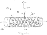
- Fig. 1b illustrates a system 20 for electrospinning the second and third sets of fibers over a stent 22 placed on a first set of fibers 24 that has been pre-formed into an inner layer over a mandrel 26.
- the outer part of the stent 22 is directly in the line of polymer spinning jet 28 directed from nozzle 30.
- the "wet" second set of fibers is applied to the outwardly directed surfaces of the stent 22 and the inner layer 24, there will be some diffusion of the deposited wet fibers to the inside surface of the stent (between the stent and the inner layer) to reinforce the connection and bonding.
- further bonding is formed through the connection of the inner layer to the outer layer via the wet adhesive or glue layer.
- the stents may have any conventional scaffold structure of the type used in medical procedures.
- the scaffolds may be formed from malleable materials, such as stainless steel, in order to be balloon exapndable.
- the scaffolds may be formed from elastic materials, such as nickel-titanium alloy, in order to be self-expanding.
- Particular constructions for both balloon-expandable and self-expanding stents are well known and described in the patent and technical literature.
- porosity of the outer layer can be controlled to promote cellular in-growth to seal off paravalvular leakage and endovascular leakage.
- a high porosity of the outer layer or "skirt" also allows the skirt to be relatively thick skirt without compromising valve crimpability.
- the electrospun layers of the present invention preferably comprise supramolecular polymers.
- Supramolecular polymers are formed when hydrogen bonding units are applied as associating end-groups of bi-functional molecules.
- the association constants must be sufficiently high to get a high degree of polymerization, which results in real polymer properties.
- This supramolecular approach bridges the gap between covalent modification and simple mixing of molecules and polymers.
- the first method leads to highly stable structures that lack dynamics. The latter, in contrast, results in very dynamic structures that lack stability.
- a particular bioactive supramolecular system that we have previously described is based on oligocaprolactone end-functionalized with 2-ureido-4[1H]-pyrimidinone (UPy) groups. These UPy-moieties strongly dimerize via quadruple hydrogen bonding and display high association constants (Ka 1 ⁇ 4 106-107L mol_1) in organic solvents. The UPy-functionalized oligocaprolactone shows much better mechanical properties than its unfunctionalized variation. These supramolecular polymer systems find already many uses in polymer applications.
- UPy 2-ureido-4[1H]-pyrimidinone
- the stents were prepared as follows. A first electrospinning solution was spun over a 29 mm cylindrical target, rotating at 100RPM, to form the inner layer of the covered stent.
- the solution was an oligocaprolactone-based supramolecular polymer having a 23% polymer concentration and a polymer to solvent (chloroform, hexafluoroisopropanol, and methanol) ratio of 60/40/3.
- the covered stents were fabricated in a controlled environment of 23° C and 35% relative humidity. After fabrication, the inner layer was removed by soaking it in water ( ⁇ 37° C) and using a spatula to physically separate the layer from the metal target. The inner layer was dried at 37° C and under vacuum.
- the inner layer and the stent were then mounted on a rotating mandrel and aluminum foil was used as a spacer to ensure that the inner layer and the mandrel had good contact.
- Additional oligocaprolactone-based supramolecular polymer (23% dissolved in chloroform, hexafluoroisopropanol, and methanol - 60/40/3) was electrospun at 9 kV (5 kV, -4 kV) to fabricate the glue/adhesive layer. After applying the glue/adhesive layer, the same solution was electrospun for 20 minutes at 8kV (7 kV, -1 kV) to create the outer layer of the stent.
Landscapes
- Engineering & Computer Science (AREA)
- Health & Medical Sciences (AREA)
- Textile Engineering (AREA)
- Mechanical Engineering (AREA)
- Chemical & Material Sciences (AREA)
- Public Health (AREA)
- Veterinary Medicine (AREA)
- Life Sciences & Earth Sciences (AREA)
- Animal Behavior & Ethology (AREA)
- General Health & Medical Sciences (AREA)
- Epidemiology (AREA)
- Medicinal Chemistry (AREA)
- Oral & Maxillofacial Surgery (AREA)
- Transplantation (AREA)
- Dermatology (AREA)
- Dispersion Chemistry (AREA)
- Heart & Thoracic Surgery (AREA)
- Surgery (AREA)
- Vascular Medicine (AREA)
- Chemical Kinetics & Catalysis (AREA)
- Prostheses (AREA)
- Materials For Medical Uses (AREA)
Claims (15)
- Verfahren zum Elektrospinnen, umfassend:(a) Bereitstellen einer Elektrospinnvorrichtung, die Folgendes umfasst:(i) ein Ziel,(ii) einen Applikator in Fluidverbindung mit einem fließfähigen Polymer, wobei der Applikator so konfiguriert ist, dass er einen Strom des fließfähigen Polymers auf das Ziel richtet,(b) Aufbringen einer ersten elektromotorische Kraft auf den Applikator und einer zweiten elektromotorischen Kraft auf das Ziel, um ein erstes elektrisches Potential dazwischen zu erzeugen;(c) Abgeben des fließfähigen Polymers durch den Applikator auf das Ziel unter ersten Abgabebedingungen, die eine erste Fließfähigkeit bereitstellen, während ein erstes elektrisches Potential angelegt wird, um einen ersten Satz Fasern zu erzeugen;(d) Einstellen der Abgabebedingungen, sodass eine zweite Fließfähigkeit bereitgestellt wird; und(e) Abgeben des fließfähigen Polymers durch den Applikator auf das Ziel nach dem Einstellen der Abgabebedingungen, während ein elektrisches Potential angelegt wird, um einen zweiten Satz Fasern zu erzeugen, wobei der zweite Satz Fasern einen im Wesentlichen abgeflachten Querschnitt aufweist.
- Verfahren nach Anspruch 1, wobei das Einstellen der Abgabebedingungen das Ändern mindestens einer von der ersten und der zweiten elektromotorischen Kraft auf den Applikator und das Ziel umfasst, um ein zweites elektrisches Potential dazwischen zu erzeugen.
- Verfahren nach Anspruch 1, wobei das Einstellen der Abgabebedingungen das Ändern eines Trennungsabstands zwischen dem Applikator und dem Ziel umfasst, um ein zweites elektrisches Potential dazwischen zu erzeugen.
- Verfahren nach Anspruch 1, wobei das Einstellen der Abgabebedingungen das Abgeben einer Mischung von mindestens dem ersten und dem zweiten fließfähigen Polymer und das Einstellen der relativen Mengen jedes fließfähigen Polymers, um die Fließfähigkeit der Mischung zu ändern, umfasst, optional wobei das Abgeben der Mischung von mindestens dem ersten und dem zweiten fließfähigen Polymer und das Einstellen der relativen Mengen jedes fließfähigen Polymers das Abgeben des mindestens ersten und zweiten Polymers aus mindestens einer ersten und einer zweiten Düse und das Einstellen der Mengen, die durch jede Düse abgegeben werden, umfasst.
- Verfahren nach Anspruch 1, wobei das fließfähige Polymer ein Polymer in einer Lösemittellösung umfasst und wobei der erste Satz Fasern eine erste Lösemittelfraktion aufweist und der zweite Satz Fasern eine zweite Lösemittelfraktion aufweist, optional wobei der zweite Satz Fasern eine höhere Lösemittelfraktion aufweist als der erste Satz Fasern, sodass der zweite Satz Fasern als ein Haftmittel für einen dritten Satz Fasern fungieren kann, wenn er über dem zweiten Satz Fasern aufgebracht wird.
- Verfahren nach Anspruch 5, ferner Folgendes umfassend:(f) Ändern mindestens einer von der ersten und der zweiten elektromotorischen Kraft auf den Applikator und das Ziel, um ein drittes elektrisches Potential dazwischen zu erzeugen; und(g) Fortsetzen, die Lösung durch den Applikator auf das Ziel abzugeben, während das dritte elektrische Potential angelegt wird, um einen dritten Satz Fasern, der eine dritte Lösemittelfraktion aufweist, über dem zweiten Satz Fasern zu erzeugen, wobei der zweite Satz Fasern als ein Haftmittel zwischen dem ersten und dem dritten Satz Fasern fungiert.
- Verfahren nach Anspruch 5, wobei der zweite Satz Fasern eine Menge des ersten Lösemittels umfasst, die ausreicht, um den Fasern Fließeigenschaften zu verleihen.
- Verfahren nach Anspruch 1, wobei der zweite Satz Fasern bandförmig ist.
- Verfahren nach Anspruch 1, wobei der zweite Satz Fasern im Durchschnitt einen abgeflachteren Querschnitt als der erste Satz Fasern aufweist.
- Verfahren nach Anspruch 1, wobei die erste und die zweite elektromotorische Kraft so ausgewählt sind, dass sie eine Potentialdifferenz im Bereich zwischen 1 kV und 150 kV bereitstellen, optional wobei die erste elektromotorische Kraft zu 50 % bis 100 %) der Potentialdifferenz beiträgt und die zweite elektromotorische Kraft zu 0 % > bis 50 %) der Potentialdifferenz beiträgt.
- Verfahren nach Anspruch 1, ferner das Aufbringen eines Trennmittels auf das Ziel vor dem Abgeben der ersten Lösung umfassend, optional wobei das Trennmittel eines von Ethanol und Polyethylenglycol oder Polyethylenoxid umfasst, optional wobei das Trennmittel durch Sprühen, Tauchen, Streichen oder Elektrospinnen aufgebracht wird.
- Verfahren nach Anspruch 11, wobei das Trennmittel durch Elektrospinnen mit einer vierten Potentialdifferenz zwischen dem Applikator und dem Ziel und Abgeben der Lösung durch den Applikator auf das Ziel, um das Trennmittel aufzubringen, während des Anlegens der vierten Potentialdifferenz aufgebracht wird.
- Verfahren nach Anspruch 11 ferner das Spülen des ersten Satzes Fasern mit einem Trennmittellösemittel, das mindestens teilweise das Trennmittel auflöst, umfassend, um es zu ermöglichen, dass der erste Satz Fasern von dem Ziel entfernt wird, optional wobei das Trennmittellösemittel wässrig ist.
- Verfahren nach Anspruch 1, ferner das Spülen des Ziels mit einem weiteren Lösemittel nach dem Elektrospinnen, um den ersten Satz Fasern zu erzeugen, umfassend, um den ersten Satz Fasern zu entfernen, wobei das weitere Lösemittel mindestens teilweise die Schicht auflöst, die das Zieltrennmittel enthält, optional wobei das weitere Lösemittel nicht das Polymer auflöst.
- Verfahren nach Anspruch 1, wobei das Ziel ein Material umfasst, das aus der Gruppe ausgewählt ist, die aus Aluminium, Edelstahl, Kupfer und Chrom besteht.
Applications Claiming Priority (2)
| Application Number | Priority Date | Filing Date | Title |
|---|---|---|---|
| US201562236073P | 2015-10-01 | 2015-10-01 | |
| PCT/IB2016/001529 WO2017055926A1 (en) | 2015-10-01 | 2016-10-03 | Methods for electrospin coating and laminating of endoluminal prostheses |
Publications (2)
| Publication Number | Publication Date |
|---|---|
| EP3355949A1 EP3355949A1 (de) | 2018-08-08 |
| EP3355949B1 true EP3355949B1 (de) | 2022-04-20 |
Family
ID=57249837
Family Applications (1)
| Application Number | Title | Priority Date | Filing Date |
|---|---|---|---|
| EP16791670.9A Active EP3355949B1 (de) | 2015-10-01 | 2016-10-03 | Verfahren zur beschichtung und kaschierung von endoluminalprothesen mittels elektrospinning |
Country Status (6)
| Country | Link |
|---|---|
| US (1) | US10876222B2 (de) |
| EP (1) | EP3355949B1 (de) |
| JP (1) | JP6829254B2 (de) |
| CN (1) | CN108136078B (de) |
| ES (1) | ES2913723T3 (de) |
| WO (1) | WO2017055926A1 (de) |
Families Citing this family (9)
| Publication number | Priority date | Publication date | Assignee | Title |
|---|---|---|---|---|
| US10456237B2 (en) * | 2016-03-07 | 2019-10-29 | Boston Scientific Scimed, Inc. | Esophageal stent including a valve member |
| JP6972152B2 (ja) * | 2017-03-31 | 2021-11-24 | ゼルティス ベーフェー | 心血管移植片 |
| US10953139B2 (en) * | 2017-12-28 | 2021-03-23 | Xeltis Ag | Electro-spun cardiovascular implant |
| PL238746B1 (pl) * | 2018-07-24 | 2021-09-27 | American Heart Of Poland Spolka Akcyjna | Sposób formowania prefabrykatów wykorzystywanych w produkcji systemów przezcewnikowej implantacji zastawki aortalnej oraz prefabrykat zastawki aortalnej |
| CN109248340B (zh) * | 2018-09-18 | 2021-04-23 | 武汉纺织大学 | 一种纤维基人造血管的制备方法 |
| CN116528801A (zh) * | 2020-11-13 | 2023-08-01 | 谢尔蒂斯股份公司 | 用于两个管状结构之间的内源性组织恢复的移植物装置 |
| US20250221835A1 (en) * | 2021-12-31 | 2025-07-10 | Biotyx Medical (Shenzhen) Co., Ltd. | Covered Stent System and Preparation Method Thereof |
| US12127928B2 (en) | 2022-12-06 | 2024-10-29 | Medical 21, Inc. | Composite implant |
| CN117752463B (zh) * | 2024-02-20 | 2024-05-14 | 北京阿迈特医疗器械有限公司 | 一种可植入人工血管或人工气管及其制备装置和方法 |
Family Cites Families (22)
| Publication number | Priority date | Publication date | Assignee | Title |
|---|---|---|---|---|
| US6376588B1 (en) * | 1991-10-15 | 2002-04-23 | Huntsman Petrochemical Corporation | Water soluble mold release composition for elastomeric compounds |
| US7244272B2 (en) * | 2000-12-19 | 2007-07-17 | Nicast Ltd. | Vascular prosthesis and method for production thereof |
| US20020084178A1 (en) * | 2000-12-19 | 2002-07-04 | Nicast Corporation Ltd. | Method and apparatus for manufacturing polymer fiber shells via electrospinning |
| US20030211135A1 (en) | 2002-04-11 | 2003-11-13 | Greenhalgh Skott E. | Stent having electrospun covering and method |
| JP4496360B2 (ja) * | 2003-04-24 | 2010-07-07 | 国立大学法人九州大学 | 医療用高分子ナノ・マイクロファイバー |
| WO2006080008A2 (en) | 2005-01-25 | 2006-08-03 | Nicast Ltd. | Artificial vascular prosthesis |
| EP2059191A4 (de) | 2006-06-21 | 2010-03-31 | Aortx Inc | Implantiersysteme für eine klappenprothese |
| EP2161360B1 (de) * | 2007-06-26 | 2014-01-15 | Idemitsu Kosan Co., Ltd. | Elastischer vliesstoff, verfahren zur herstellung sowie textilprodukt, umfassend den elastischen vliesstoff |
| US7824601B1 (en) * | 2007-11-14 | 2010-11-02 | Abbott Cardiovascular Systems Inc. | Process of making a tubular implantable medical device |
| US20130238086A1 (en) | 2009-01-16 | 2013-09-12 | Zeus Industrial Products, Inc. | Electrospun PTFE Encapsulated Stent & Method of Manufature |
| US20130268062A1 (en) * | 2012-04-05 | 2013-10-10 | Zeus Industrial Products, Inc. | Composite prosthetic devices |
| US8637109B2 (en) * | 2009-12-03 | 2014-01-28 | Cook Medical Technologies Llc | Manufacturing methods for covering endoluminal prostheses |
| CN101732117B (zh) * | 2009-12-17 | 2012-01-04 | 武汉科技学院 | 一种胆管支架及其制备方法 |
| KR101187212B1 (ko) * | 2010-12-30 | 2012-10-02 | 주식회사 엠아이텍 | 전기방사를 이용한 담관의 양성협착 치료용 약물방출 스텐트의 제조 방법 |
| DE102011012501A1 (de) * | 2011-02-25 | 2012-08-30 | Phenox Gmbh | Implantat mit Faservlies |
| JP5665803B2 (ja) | 2011-07-15 | 2015-02-04 | クック メディカル テクノロジーズ エルエルシーCook Medical Technologies Llc | グラフト層をエレクトロスピニングする方法 |
| CN102430157B (zh) * | 2011-11-29 | 2013-11-27 | 武汉纺织大学 | 一种内覆膜的医用支架及其制备方法 |
| US20150298070A1 (en) * | 2012-12-10 | 2015-10-22 | Emd Millipore Corporation | Ultraporous Nanofiber Mats And Uses Thereof |
| US10154918B2 (en) | 2012-12-28 | 2018-12-18 | Cook Medical Technologies Llc | Endoluminal prosthesis with fiber matrix |
| CN103110984A (zh) * | 2013-02-20 | 2013-05-22 | 上海典范医疗科技有限公司 | 止血聚乳酸防粘连膜的制备方法 |
| CN103462726A (zh) * | 2013-08-28 | 2013-12-25 | 苏州英络医疗器械有限公司 | 一种新型覆膜支架及其制作方法 |
| CN103655015A (zh) * | 2013-12-26 | 2014-03-26 | 张建平 | 一种载药纳米纤维膜胆道支架及其制备方法 |
-
2016
- 2016-10-03 EP EP16791670.9A patent/EP3355949B1/de active Active
- 2016-10-03 CN CN201680057519.0A patent/CN108136078B/zh active Active
- 2016-10-03 JP JP2018516441A patent/JP6829254B2/ja active Active
- 2016-10-03 US US15/763,197 patent/US10876222B2/en active Active
- 2016-10-03 WO PCT/IB2016/001529 patent/WO2017055926A1/en not_active Ceased
- 2016-10-03 ES ES16791670T patent/ES2913723T3/es active Active
Also Published As
| Publication number | Publication date |
|---|---|
| CN108136078A (zh) | 2018-06-08 |
| JP2018531069A (ja) | 2018-10-25 |
| US20180274131A1 (en) | 2018-09-27 |
| EP3355949A1 (de) | 2018-08-08 |
| US10876222B2 (en) | 2020-12-29 |
| ES2913723T3 (es) | 2022-06-06 |
| CN108136078B (zh) | 2021-10-12 |
| WO2017055926A1 (en) | 2017-04-06 |
| JP6829254B2 (ja) | 2021-02-10 |
Similar Documents
| Publication | Publication Date | Title |
|---|---|---|
| EP3355949B1 (de) | Verfahren zur beschichtung und kaschierung von endoluminalprothesen mittels elektrospinning | |
| JP2018531069A6 (ja) | 管腔内プロテーゼの電気スピンコーティングおよび積層のための方法 | |
| EP1164972B1 (de) | Kunststoffbeschichteter stent | |
| US6156064A (en) | Stent-graft-membrane and method of making the same | |
| EP1093772B1 (de) | Ausdehnbares, unterstützendes sowie verzweigtes endoluminales Transplantat | |
| US8591564B2 (en) | Hypotube endoluminal device and method | |
| CN109303628B (zh) | 防止支架移位的可溶性或可降解粘合剂聚合物 | |
| US9517123B2 (en) | Endovascular prosthesis and a method of connecting a structural component and a woven graft material | |
| EP2779957A2 (de) | Gitter | |
| US11000376B2 (en) | Device and associated percutaneous minimally invasive method for creating a venous valve | |
| US20120029612A1 (en) | Covered toroid stent and methods of manufacture | |
| US20180271639A1 (en) | Medical devices for controlled drug release | |
| EP1965731B1 (de) | Endoprothese und verfahren zur verbindung eines stützgerüsts mit gewebtem prothesenmaterial | |
| AU736081B2 (en) | Expandable supportive bifurcated endoluminal grafts |
Legal Events
| Date | Code | Title | Description |
|---|---|---|---|
| STAA | Information on the status of an ep patent application or granted ep patent |
Free format text: STATUS: UNKNOWN |
|
| STAA | Information on the status of an ep patent application or granted ep patent |
Free format text: STATUS: THE INTERNATIONAL PUBLICATION HAS BEEN MADE |
|
| PUAI | Public reference made under article 153(3) epc to a published international application that has entered the european phase |
Free format text: ORIGINAL CODE: 0009012 |
|
| STAA | Information on the status of an ep patent application or granted ep patent |
Free format text: STATUS: REQUEST FOR EXAMINATION WAS MADE |
|
| 17P | Request for examination filed |
Effective date: 20180312 |
|
| AK | Designated contracting states |
Kind code of ref document: A1 Designated state(s): AL AT BE BG CH CY CZ DE DK EE ES FI FR GB GR HR HU IE IS IT LI LT LU LV MC MK MT NL NO PL PT RO RS SE SI SK SM TR |
|
| AX | Request for extension of the european patent |
Extension state: BA ME |
|
| DAV | Request for validation of the european patent (deleted) | ||
| DAX | Request for extension of the european patent (deleted) | ||
| STAA | Information on the status of an ep patent application or granted ep patent |
Free format text: STATUS: EXAMINATION IS IN PROGRESS |
|
| RAP1 | Party data changed (applicant data changed or rights of an application transferred) |
Owner name: NAZ, CHRISTOPHE PIERRE EDOUARD Owner name: XELTIS AG |
|
| 17Q | First examination report despatched |
Effective date: 20200706 |
|
| REG | Reference to a national code |
Ref country code: DE Ref legal event code: R079 Ref document number: 602016071326 Country of ref document: DE Free format text: PREVIOUS MAIN CLASS: A61L0031100000 Ipc: A61L0027340000 |
|
| RIC1 | Information provided on ipc code assigned before grant |
Ipc: D01D 5/00 20060101ALI20211109BHEP Ipc: A61L 31/10 20060101ALI20211109BHEP Ipc: D04H 1/728 20120101ALI20211109BHEP Ipc: A61L 27/34 20060101AFI20211109BHEP |
|
| GRAP | Despatch of communication of intention to grant a patent |
Free format text: ORIGINAL CODE: EPIDOSNIGR1 |
|
| STAA | Information on the status of an ep patent application or granted ep patent |
Free format text: STATUS: GRANT OF PATENT IS INTENDED |
|
| RAP3 | Party data changed (applicant data changed or rights of an application transferred) |
Owner name: XELTIS AG |
|
| INTG | Intention to grant announced |
Effective date: 20211221 |
|
| GRAS | Grant fee paid |
Free format text: ORIGINAL CODE: EPIDOSNIGR3 |
|
| GRAA | (expected) grant |
Free format text: ORIGINAL CODE: 0009210 |
|
| STAA | Information on the status of an ep patent application or granted ep patent |
Free format text: STATUS: THE PATENT HAS BEEN GRANTED |
|
| AK | Designated contracting states |
Kind code of ref document: B1 Designated state(s): AL AT BE BG CH CY CZ DE DK EE ES FI FR GB GR HR HU IE IS IT LI LT LU LV MC MK MT NL NO PL PT RO RS SE SI SK SM TR |
|
| REG | Reference to a national code |
Ref country code: GB Ref legal event code: FG4D |
|
| REG | Reference to a national code |
Ref country code: CH Ref legal event code: EP |
|
| REG | Reference to a national code |
Ref country code: IE Ref legal event code: FG4D |
|
| REG | Reference to a national code |
Ref country code: DE Ref legal event code: R096 Ref document number: 602016071326 Country of ref document: DE |
|
| REG | Reference to a national code |
Ref country code: AT Ref legal event code: REF Ref document number: 1484676 Country of ref document: AT Kind code of ref document: T Effective date: 20220515 |
|
| REG | Reference to a national code |
Ref country code: NL Ref legal event code: FP |
|
| REG | Reference to a national code |
Ref country code: ES Ref legal event code: FG2A Ref document number: 2913723 Country of ref document: ES Kind code of ref document: T3 Effective date: 20220606 |
|
| REG | Reference to a national code |
Ref country code: LT Ref legal event code: MG9D |
|
| REG | Reference to a national code |
Ref country code: AT Ref legal event code: MK05 Ref document number: 1484676 Country of ref document: AT Kind code of ref document: T Effective date: 20220420 |
|
| PG25 | Lapsed in a contracting state [announced via postgrant information from national office to epo] |
Ref country code: SE Free format text: LAPSE BECAUSE OF FAILURE TO SUBMIT A TRANSLATION OF THE DESCRIPTION OR TO PAY THE FEE WITHIN THE PRESCRIBED TIME-LIMIT Effective date: 20220420 Ref country code: PT Free format text: LAPSE BECAUSE OF FAILURE TO SUBMIT A TRANSLATION OF THE DESCRIPTION OR TO PAY THE FEE WITHIN THE PRESCRIBED TIME-LIMIT Effective date: 20220822 Ref country code: NO Free format text: LAPSE BECAUSE OF FAILURE TO SUBMIT A TRANSLATION OF THE DESCRIPTION OR TO PAY THE FEE WITHIN THE PRESCRIBED TIME-LIMIT Effective date: 20220720 Ref country code: LT Free format text: LAPSE BECAUSE OF FAILURE TO SUBMIT A TRANSLATION OF THE DESCRIPTION OR TO PAY THE FEE WITHIN THE PRESCRIBED TIME-LIMIT Effective date: 20220420 Ref country code: HR Free format text: LAPSE BECAUSE OF FAILURE TO SUBMIT A TRANSLATION OF THE DESCRIPTION OR TO PAY THE FEE WITHIN THE PRESCRIBED TIME-LIMIT Effective date: 20220420 Ref country code: GR Free format text: LAPSE BECAUSE OF FAILURE TO SUBMIT A TRANSLATION OF THE DESCRIPTION OR TO PAY THE FEE WITHIN THE PRESCRIBED TIME-LIMIT Effective date: 20220721 Ref country code: FI Free format text: LAPSE BECAUSE OF FAILURE TO SUBMIT A TRANSLATION OF THE DESCRIPTION OR TO PAY THE FEE WITHIN THE PRESCRIBED TIME-LIMIT Effective date: 20220420 Ref country code: BG Free format text: LAPSE BECAUSE OF FAILURE TO SUBMIT A TRANSLATION OF THE DESCRIPTION OR TO PAY THE FEE WITHIN THE PRESCRIBED TIME-LIMIT Effective date: 20220720 Ref country code: AT Free format text: LAPSE BECAUSE OF FAILURE TO SUBMIT A TRANSLATION OF THE DESCRIPTION OR TO PAY THE FEE WITHIN THE PRESCRIBED TIME-LIMIT Effective date: 20220420 |
|
| PG25 | Lapsed in a contracting state [announced via postgrant information from national office to epo] |
Ref country code: RS Free format text: LAPSE BECAUSE OF FAILURE TO SUBMIT A TRANSLATION OF THE DESCRIPTION OR TO PAY THE FEE WITHIN THE PRESCRIBED TIME-LIMIT Effective date: 20220420 Ref country code: PL Free format text: LAPSE BECAUSE OF FAILURE TO SUBMIT A TRANSLATION OF THE DESCRIPTION OR TO PAY THE FEE WITHIN THE PRESCRIBED TIME-LIMIT Effective date: 20220420 Ref country code: LV Free format text: LAPSE BECAUSE OF FAILURE TO SUBMIT A TRANSLATION OF THE DESCRIPTION OR TO PAY THE FEE WITHIN THE PRESCRIBED TIME-LIMIT Effective date: 20220420 Ref country code: IS Free format text: LAPSE BECAUSE OF FAILURE TO SUBMIT A TRANSLATION OF THE DESCRIPTION OR TO PAY THE FEE WITHIN THE PRESCRIBED TIME-LIMIT Effective date: 20220820 |
|
| REG | Reference to a national code |
Ref country code: DE Ref legal event code: R097 Ref document number: 602016071326 Country of ref document: DE |
|
| PG25 | Lapsed in a contracting state [announced via postgrant information from national office to epo] |
Ref country code: SM Free format text: LAPSE BECAUSE OF FAILURE TO SUBMIT A TRANSLATION OF THE DESCRIPTION OR TO PAY THE FEE WITHIN THE PRESCRIBED TIME-LIMIT Effective date: 20220420 Ref country code: SK Free format text: LAPSE BECAUSE OF FAILURE TO SUBMIT A TRANSLATION OF THE DESCRIPTION OR TO PAY THE FEE WITHIN THE PRESCRIBED TIME-LIMIT Effective date: 20220420 Ref country code: RO Free format text: LAPSE BECAUSE OF FAILURE TO SUBMIT A TRANSLATION OF THE DESCRIPTION OR TO PAY THE FEE WITHIN THE PRESCRIBED TIME-LIMIT Effective date: 20220420 Ref country code: EE Free format text: LAPSE BECAUSE OF FAILURE TO SUBMIT A TRANSLATION OF THE DESCRIPTION OR TO PAY THE FEE WITHIN THE PRESCRIBED TIME-LIMIT Effective date: 20220420 Ref country code: DK Free format text: LAPSE BECAUSE OF FAILURE TO SUBMIT A TRANSLATION OF THE DESCRIPTION OR TO PAY THE FEE WITHIN THE PRESCRIBED TIME-LIMIT Effective date: 20220420 Ref country code: CZ Free format text: LAPSE BECAUSE OF FAILURE TO SUBMIT A TRANSLATION OF THE DESCRIPTION OR TO PAY THE FEE WITHIN THE PRESCRIBED TIME-LIMIT Effective date: 20220420 |
|
| PLBE | No opposition filed within time limit |
Free format text: ORIGINAL CODE: 0009261 |
|
| STAA | Information on the status of an ep patent application or granted ep patent |
Free format text: STATUS: NO OPPOSITION FILED WITHIN TIME LIMIT |
|
| 26N | No opposition filed |
Effective date: 20230123 |
|
| PG25 | Lapsed in a contracting state [announced via postgrant information from national office to epo] |
Ref country code: AL Free format text: LAPSE BECAUSE OF FAILURE TO SUBMIT A TRANSLATION OF THE DESCRIPTION OR TO PAY THE FEE WITHIN THE PRESCRIBED TIME-LIMIT Effective date: 20220420 |
|
| PG25 | Lapsed in a contracting state [announced via postgrant information from national office to epo] |
Ref country code: SI Free format text: LAPSE BECAUSE OF FAILURE TO SUBMIT A TRANSLATION OF THE DESCRIPTION OR TO PAY THE FEE WITHIN THE PRESCRIBED TIME-LIMIT Effective date: 20220420 Ref country code: MC Free format text: LAPSE BECAUSE OF FAILURE TO SUBMIT A TRANSLATION OF THE DESCRIPTION OR TO PAY THE FEE WITHIN THE PRESCRIBED TIME-LIMIT Effective date: 20220420 |
|
| PG25 | Lapsed in a contracting state [announced via postgrant information from national office to epo] |
Ref country code: LU Free format text: LAPSE BECAUSE OF NON-PAYMENT OF DUE FEES Effective date: 20221003 |
|
| P01 | Opt-out of the competence of the unified patent court (upc) registered |
Effective date: 20230526 |
|
| PG25 | Lapsed in a contracting state [announced via postgrant information from national office to epo] |
Ref country code: HU Free format text: LAPSE BECAUSE OF FAILURE TO SUBMIT A TRANSLATION OF THE DESCRIPTION OR TO PAY THE FEE WITHIN THE PRESCRIBED TIME-LIMIT; INVALID AB INITIO Effective date: 20161003 |
|
| PG25 | Lapsed in a contracting state [announced via postgrant information from national office to epo] |
Ref country code: CY Free format text: LAPSE BECAUSE OF FAILURE TO SUBMIT A TRANSLATION OF THE DESCRIPTION OR TO PAY THE FEE WITHIN THE PRESCRIBED TIME-LIMIT Effective date: 20220420 |
|
| PG25 | Lapsed in a contracting state [announced via postgrant information from national office to epo] |
Ref country code: MK Free format text: LAPSE BECAUSE OF FAILURE TO SUBMIT A TRANSLATION OF THE DESCRIPTION OR TO PAY THE FEE WITHIN THE PRESCRIBED TIME-LIMIT Effective date: 20220420 |
|
| PG25 | Lapsed in a contracting state [announced via postgrant information from national office to epo] |
Ref country code: TR Free format text: LAPSE BECAUSE OF FAILURE TO SUBMIT A TRANSLATION OF THE DESCRIPTION OR TO PAY THE FEE WITHIN THE PRESCRIBED TIME-LIMIT Effective date: 20220420 |
|
| PG25 | Lapsed in a contracting state [announced via postgrant information from national office to epo] |
Ref country code: MT Free format text: LAPSE BECAUSE OF FAILURE TO SUBMIT A TRANSLATION OF THE DESCRIPTION OR TO PAY THE FEE WITHIN THE PRESCRIBED TIME-LIMIT Effective date: 20220420 |
|
| PG25 | Lapsed in a contracting state [announced via postgrant information from national office to epo] |
Ref country code: BG Free format text: LAPSE BECAUSE OF FAILURE TO SUBMIT A TRANSLATION OF THE DESCRIPTION OR TO PAY THE FEE WITHIN THE PRESCRIBED TIME-LIMIT Effective date: 20220420 |
|
| PG25 | Lapsed in a contracting state [announced via postgrant information from national office to epo] |
Ref country code: BG Free format text: LAPSE BECAUSE OF FAILURE TO SUBMIT A TRANSLATION OF THE DESCRIPTION OR TO PAY THE FEE WITHIN THE PRESCRIBED TIME-LIMIT Effective date: 20220420 |
|
| PGFP | Annual fee paid to national office [announced via postgrant information from national office to epo] |
Ref country code: DE Payment date: 20241210 Year of fee payment: 9 |
|
| PGFP | Annual fee paid to national office [announced via postgrant information from national office to epo] |
Ref country code: BE Payment date: 20241009 Year of fee payment: 9 |
|
| PGFP | Annual fee paid to national office [announced via postgrant information from national office to epo] |
Ref country code: FR Payment date: 20241030 Year of fee payment: 9 |
|
| PGFP | Annual fee paid to national office [announced via postgrant information from national office to epo] |
Ref country code: IE Payment date: 20241025 Year of fee payment: 9 |
|
| PGFP | Annual fee paid to national office [announced via postgrant information from national office to epo] |
Ref country code: IT Payment date: 20241025 Year of fee payment: 9 Ref country code: ES Payment date: 20241104 Year of fee payment: 9 |
|
| PGFP | Annual fee paid to national office [announced via postgrant information from national office to epo] |
Ref country code: CH Payment date: 20241101 Year of fee payment: 9 |
|
| PGFP | Annual fee paid to national office [announced via postgrant information from national office to epo] |
Ref country code: GB Payment date: 20250922 Year of fee payment: 10 |
|
| REG | Reference to a national code |
Ref country code: CH Ref legal event code: U11 Free format text: ST27 STATUS EVENT CODE: U-0-0-U10-U11 (AS PROVIDED BY THE NATIONAL OFFICE) Effective date: 20251101 |
|
| PGFP | Annual fee paid to national office [announced via postgrant information from national office to epo] |
Ref country code: NL Payment date: 20251014 Year of fee payment: 10 |