EP3355949B1 - Methods for electrospin coating and laminating of endoluminal prostheses - Google Patents
Methods for electrospin coating and laminating of endoluminal prostheses Download PDFInfo
- Publication number
- EP3355949B1 EP3355949B1 EP16791670.9A EP16791670A EP3355949B1 EP 3355949 B1 EP3355949 B1 EP 3355949B1 EP 16791670 A EP16791670 A EP 16791670A EP 3355949 B1 EP3355949 B1 EP 3355949B1
- Authority
- EP
- European Patent Office
- Prior art keywords
- fibers
- target
- applicator
- solvent
- release agent
- Prior art date
- Legal status (The legal status is an assumption and is not a legal conclusion. Google has not performed a legal analysis and makes no representation as to the accuracy of the status listed.)
- Active
Links
- 238000000034 method Methods 0.000 title claims description 35
- 239000011248 coating agent Substances 0.000 title description 5
- 238000000576 coating method Methods 0.000 title description 5
- 238000010030 laminating Methods 0.000 title description 3
- 239000000835 fiber Substances 0.000 claims description 73
- 229920000642 polymer Polymers 0.000 claims description 45
- 239000002904 solvent Substances 0.000 claims description 33
- 239000003795 chemical substances by application Substances 0.000 claims description 25
- 238000001523 electrospinning Methods 0.000 claims description 22
- 239000000463 material Substances 0.000 claims description 21
- 230000009969 flowable effect Effects 0.000 claims description 14
- 239000000853 adhesive Substances 0.000 claims description 6
- 230000001070 adhesive effect Effects 0.000 claims description 6
- 239000000203 mixture Substances 0.000 claims description 5
- LFQSCWFLJHTTHZ-UHFFFAOYSA-N Ethanol Chemical compound CCO LFQSCWFLJHTTHZ-UHFFFAOYSA-N 0.000 claims description 4
- 229910052782 aluminium Inorganic materials 0.000 claims description 4
- XAGFODPZIPBFFR-UHFFFAOYSA-N aluminium Chemical compound [Al] XAGFODPZIPBFFR-UHFFFAOYSA-N 0.000 claims description 4
- 230000008859 change Effects 0.000 claims description 4
- 239000002202 Polyethylene glycol Substances 0.000 claims description 3
- 238000007598 dipping method Methods 0.000 claims description 3
- 238000010422 painting Methods 0.000 claims description 3
- 229920001223 polyethylene glycol Polymers 0.000 claims description 3
- 238000005507 spraying Methods 0.000 claims description 3
- 239000010935 stainless steel Substances 0.000 claims description 3
- 229910001220 stainless steel Inorganic materials 0.000 claims description 3
- VYZAMTAEIAYCRO-UHFFFAOYSA-N Chromium Chemical compound [Cr] VYZAMTAEIAYCRO-UHFFFAOYSA-N 0.000 claims description 2
- RYGMFSIKBFXOCR-UHFFFAOYSA-N Copper Chemical compound [Cu] RYGMFSIKBFXOCR-UHFFFAOYSA-N 0.000 claims description 2
- 229920003171 Poly (ethylene oxide) Polymers 0.000 claims description 2
- 229910052804 chromium Inorganic materials 0.000 claims description 2
- 239000011651 chromium Substances 0.000 claims description 2
- 238000004891 communication Methods 0.000 claims description 2
- 229910052802 copper Inorganic materials 0.000 claims description 2
- 239000010949 copper Substances 0.000 claims description 2
- 239000012530 fluid Substances 0.000 claims description 2
- 238000000926 separation method Methods 0.000 claims description 2
- 239000010410 layer Substances 0.000 description 53
- 238000002788 crimping Methods 0.000 description 19
- 239000000243 solution Substances 0.000 description 19
- 230000008439 repair process Effects 0.000 description 11
- 238000011084 recovery Methods 0.000 description 9
- 239000012790 adhesive layer Substances 0.000 description 7
- 238000004519 manufacturing process Methods 0.000 description 7
- 206010002329 Aneurysm Diseases 0.000 description 6
- 208000001750 Endoleak Diseases 0.000 description 6
- OKKJLVBELUTLKV-UHFFFAOYSA-N Methanol Chemical compound OC OKKJLVBELUTLKV-UHFFFAOYSA-N 0.000 description 6
- 208000002223 abdominal aortic aneurysm Diseases 0.000 description 6
- 208000007474 aortic aneurysm Diseases 0.000 description 5
- 229920002677 supramolecular polymer Polymers 0.000 description 5
- HEDRZPFGACZZDS-UHFFFAOYSA-N Chloroform Chemical compound ClC(Cl)Cl HEDRZPFGACZZDS-UHFFFAOYSA-N 0.000 description 4
- 238000013459 approach Methods 0.000 description 4
- 238000002513 implantation Methods 0.000 description 4
- 238000007726 management method Methods 0.000 description 4
- 229920001343 polytetrafluoroethylene Polymers 0.000 description 4
- 239000004810 polytetrafluoroethylene Substances 0.000 description 4
- 206010064396 Stent-graft endoleak Diseases 0.000 description 3
- 230000005684 electric field Effects 0.000 description 3
- 239000003292 glue Substances 0.000 description 3
- 210000003709 heart valve Anatomy 0.000 description 3
- 238000009987 spinning Methods 0.000 description 3
- XUMIQAOMRDRPMD-UHFFFAOYSA-N (6-oxo-1h-pyrimidin-2-yl)urea Chemical compound NC(=O)NC1=NC(=O)C=CN1 XUMIQAOMRDRPMD-UHFFFAOYSA-N 0.000 description 2
- BYEAHWXPCBROCE-UHFFFAOYSA-N 1,1,1,3,3,3-hexafluoropropan-2-ol Chemical compound FC(F)(F)C(O)C(F)(F)F BYEAHWXPCBROCE-UHFFFAOYSA-N 0.000 description 2
- 210000001765 aortic valve Anatomy 0.000 description 2
- 210000003445 biliary tract Anatomy 0.000 description 2
- 230000000975 bioactive effect Effects 0.000 description 2
- 230000015572 biosynthetic process Effects 0.000 description 2
- 230000008021 deposition Effects 0.000 description 2
- 238000001514 detection method Methods 0.000 description 2
- 238000001035 drying Methods 0.000 description 2
- 239000011888 foil Substances 0.000 description 2
- 239000001257 hydrogen Substances 0.000 description 2
- 229910052739 hydrogen Inorganic materials 0.000 description 2
- 238000003384 imaging method Methods 0.000 description 2
- 230000004048 modification Effects 0.000 description 2
- 238000012986 modification Methods 0.000 description 2
- 238000003032 molecular docking Methods 0.000 description 2
- -1 polytetrafluoroethylene Polymers 0.000 description 2
- 238000002791 soaking Methods 0.000 description 2
- 210000000115 thoracic cavity Anatomy 0.000 description 2
- 230000002792 vascular Effects 0.000 description 2
- 210000005166 vasculature Anatomy 0.000 description 2
- 238000011179 visual inspection Methods 0.000 description 2
- 238000002166 wet spinning Methods 0.000 description 2
- 208000032750 Device leakage Diseases 0.000 description 1
- 239000004698 Polyethylene Substances 0.000 description 1
- 201000008982 Thoracic Aortic Aneurysm Diseases 0.000 description 1
- 238000002583 angiography Methods 0.000 description 1
- 210000000702 aorta abdominal Anatomy 0.000 description 1
- 239000007864 aqueous solution Substances 0.000 description 1
- 230000004888 barrier function Effects 0.000 description 1
- 230000009286 beneficial effect Effects 0.000 description 1
- 229920002988 biodegradable polymer Polymers 0.000 description 1
- 239000004621 biodegradable polymer Substances 0.000 description 1
- 210000003123 bronchiole Anatomy 0.000 description 1
- 210000004027 cell Anatomy 0.000 description 1
- 230000010261 cell growth Effects 0.000 description 1
- 230000001413 cellular effect Effects 0.000 description 1
- 238000010968 computed tomography angiography Methods 0.000 description 1
- 239000004020 conductor Substances 0.000 description 1
- 238000010276 construction Methods 0.000 description 1
- 230000032798 delamination Effects 0.000 description 1
- 230000003111 delayed effect Effects 0.000 description 1
- 238000009792 diffusion process Methods 0.000 description 1
- 230000010339 dilation Effects 0.000 description 1
- 239000003814 drug Substances 0.000 description 1
- 229940079593 drug Drugs 0.000 description 1
- 230000004064 dysfunction Effects 0.000 description 1
- 230000002526 effect on cardiovascular system Effects 0.000 description 1
- 239000013013 elastic material Substances 0.000 description 1
- 230000008030 elimination Effects 0.000 description 1
- 238000003379 elimination reaction Methods 0.000 description 1
- 210000002889 endothelial cell Anatomy 0.000 description 1
- 210000003238 esophagus Anatomy 0.000 description 1
- 238000002474 experimental method Methods 0.000 description 1
- 238000005562 fading Methods 0.000 description 1
- 239000007789 gas Substances 0.000 description 1
- 239000007943 implant Substances 0.000 description 1
- 238000001727 in vivo Methods 0.000 description 1
- 230000010354 integration Effects 0.000 description 1
- 230000003993 interaction Effects 0.000 description 1
- 238000002697 interventional radiology Methods 0.000 description 1
- 230000000873 masking effect Effects 0.000 description 1
- 229910052751 metal Inorganic materials 0.000 description 1
- 239000002184 metal Substances 0.000 description 1
- 238000002156 mixing Methods 0.000 description 1
- 229910001000 nickel titanium Inorganic materials 0.000 description 1
- 239000012074 organic phase Substances 0.000 description 1
- 239000003960 organic solvent Substances 0.000 description 1
- 230000002093 peripheral effect Effects 0.000 description 1
- 238000009546 plain radiography Methods 0.000 description 1
- 229920000573 polyethylene Polymers 0.000 description 1
- 229920005594 polymer fiber Polymers 0.000 description 1
- 238000006116 polymerization reaction Methods 0.000 description 1
- 230000002265 prevention Effects 0.000 description 1
- 230000008569 process Effects 0.000 description 1
- 230000002685 pulmonary effect Effects 0.000 description 1
- 210000003102 pulmonary valve Anatomy 0.000 description 1
- 230000009467 reduction Effects 0.000 description 1
- 230000002787 reinforcement Effects 0.000 description 1
- 239000013557 residual solvent Substances 0.000 description 1
- 238000012552 review Methods 0.000 description 1
- 125000006850 spacer group Chemical group 0.000 description 1
- 230000002885 thrombogenetic effect Effects 0.000 description 1
- 238000002604 ultrasonography Methods 0.000 description 1
- 210000001635 urinary tract Anatomy 0.000 description 1
- 230000002861 ventricular Effects 0.000 description 1
- XLYOFNOQVPJJNP-UHFFFAOYSA-N water Substances O XLYOFNOQVPJJNP-UHFFFAOYSA-N 0.000 description 1
Images


Classifications
-
- D—TEXTILES; PAPER
- D01—NATURAL OR MAN-MADE THREADS OR FIBRES; SPINNING
- D01D—MECHANICAL METHODS OR APPARATUS IN THE MANUFACTURE OF ARTIFICIAL FILAMENTS, THREADS, FIBRES, BRISTLES OR RIBBONS
- D01D5/00—Formation of filaments, threads, or the like
- D01D5/0007—Electro-spinning
- D01D5/0061—Electro-spinning characterised by the electro-spinning apparatus
- D01D5/0076—Electro-spinning characterised by the electro-spinning apparatus characterised by the collecting device, e.g. drum, wheel, endless belt, plate or grid
- D01D5/0084—Coating by electro-spinning, i.e. the electro-spun fibres are not removed from the collecting device but remain integral with it, e.g. coating of prostheses
-
- A—HUMAN NECESSITIES
- A61—MEDICAL OR VETERINARY SCIENCE; HYGIENE
- A61L—METHODS OR APPARATUS FOR STERILISING MATERIALS OR OBJECTS IN GENERAL; DISINFECTION, STERILISATION OR DEODORISATION OF AIR; CHEMICAL ASPECTS OF BANDAGES, DRESSINGS, ABSORBENT PADS OR SURGICAL ARTICLES; MATERIALS FOR BANDAGES, DRESSINGS, ABSORBENT PADS OR SURGICAL ARTICLES
- A61L27/00—Materials for grafts or prostheses or for coating grafts or prostheses
- A61L27/14—Macromolecular materials
- A61L27/18—Macromolecular materials obtained otherwise than by reactions only involving carbon-to-carbon unsaturated bonds
-
- A—HUMAN NECESSITIES
- A61—MEDICAL OR VETERINARY SCIENCE; HYGIENE
- A61L—METHODS OR APPARATUS FOR STERILISING MATERIALS OR OBJECTS IN GENERAL; DISINFECTION, STERILISATION OR DEODORISATION OF AIR; CHEMICAL ASPECTS OF BANDAGES, DRESSINGS, ABSORBENT PADS OR SURGICAL ARTICLES; MATERIALS FOR BANDAGES, DRESSINGS, ABSORBENT PADS OR SURGICAL ARTICLES
- A61L27/00—Materials for grafts or prostheses or for coating grafts or prostheses
- A61L27/28—Materials for coating prostheses
- A61L27/34—Macromolecular materials
-
- A—HUMAN NECESSITIES
- A61—MEDICAL OR VETERINARY SCIENCE; HYGIENE
- A61L—METHODS OR APPARATUS FOR STERILISING MATERIALS OR OBJECTS IN GENERAL; DISINFECTION, STERILISATION OR DEODORISATION OF AIR; CHEMICAL ASPECTS OF BANDAGES, DRESSINGS, ABSORBENT PADS OR SURGICAL ARTICLES; MATERIALS FOR BANDAGES, DRESSINGS, ABSORBENT PADS OR SURGICAL ARTICLES
- A61L31/00—Materials for other surgical articles, e.g. stents, stent-grafts, shunts, surgical drapes, guide wires, materials for adhesion prevention, occluding devices, surgical gloves, tissue fixation devices
- A61L31/08—Materials for coatings
- A61L31/10—Macromolecular materials
-
- D—TEXTILES; PAPER
- D01—NATURAL OR MAN-MADE THREADS OR FIBRES; SPINNING
- D01D—MECHANICAL METHODS OR APPARATUS IN THE MANUFACTURE OF ARTIFICIAL FILAMENTS, THREADS, FIBRES, BRISTLES OR RIBBONS
- D01D5/00—Formation of filaments, threads, or the like
- D01D5/0007—Electro-spinning
- D01D5/0015—Electro-spinning characterised by the initial state of the material
- D01D5/003—Electro-spinning characterised by the initial state of the material the material being a polymer solution or dispersion
- D01D5/0046—Electro-spinning characterised by the initial state of the material the material being a polymer solution or dispersion the fibre formed by coagulation, i.e. wet electro-spinning
-
- D—TEXTILES; PAPER
- D01—NATURAL OR MAN-MADE THREADS OR FIBRES; SPINNING
- D01D—MECHANICAL METHODS OR APPARATUS IN THE MANUFACTURE OF ARTIFICIAL FILAMENTS, THREADS, FIBRES, BRISTLES OR RIBBONS
- D01D5/00—Formation of filaments, threads, or the like
- D01D5/0007—Electro-spinning
- D01D5/0061—Electro-spinning characterised by the electro-spinning apparatus
- D01D5/0069—Electro-spinning characterised by the electro-spinning apparatus characterised by the spinning section, e.g. capillary tube, protrusion or pin
-
- D—TEXTILES; PAPER
- D01—NATURAL OR MAN-MADE THREADS OR FIBRES; SPINNING
- D01D—MECHANICAL METHODS OR APPARATUS IN THE MANUFACTURE OF ARTIFICIAL FILAMENTS, THREADS, FIBRES, BRISTLES OR RIBBONS
- D01D5/00—Formation of filaments, threads, or the like
- D01D5/0007—Electro-spinning
- D01D5/0061—Electro-spinning characterised by the electro-spinning apparatus
- D01D5/0092—Electro-spinning characterised by the electro-spinning apparatus characterised by the electrical field, e.g. combined with a magnetic fields, using biased or alternating fields
-
- D—TEXTILES; PAPER
- D04—BRAIDING; LACE-MAKING; KNITTING; TRIMMINGS; NON-WOVEN FABRICS
- D04H—MAKING TEXTILE FABRICS, e.g. FROM FIBRES OR FILAMENTARY MATERIAL; FABRICS MADE BY SUCH PROCESSES OR APPARATUS, e.g. FELTS, NON-WOVEN FABRICS; COTTON-WOOL; WADDING ; NON-WOVEN FABRICS FROM STAPLE FIBRES, FILAMENTS OR YARNS, BONDED WITH AT LEAST ONE WEB-LIKE MATERIAL DURING THEIR CONSOLIDATION
- D04H1/00—Non-woven fabrics formed wholly or mainly of staple fibres or like relatively short fibres
- D04H1/70—Non-woven fabrics formed wholly or mainly of staple fibres or like relatively short fibres characterised by the method of forming fleeces or layers, e.g. reorientation of fibres
- D04H1/72—Non-woven fabrics formed wholly or mainly of staple fibres or like relatively short fibres characterised by the method of forming fleeces or layers, e.g. reorientation of fibres the fibres being randomly arranged
- D04H1/728—Non-woven fabrics formed wholly or mainly of staple fibres or like relatively short fibres characterised by the method of forming fleeces or layers, e.g. reorientation of fibres the fibres being randomly arranged by electro-spinning
-
- A—HUMAN NECESSITIES
- A61—MEDICAL OR VETERINARY SCIENCE; HYGIENE
- A61L—METHODS OR APPARATUS FOR STERILISING MATERIALS OR OBJECTS IN GENERAL; DISINFECTION, STERILISATION OR DEODORISATION OF AIR; CHEMICAL ASPECTS OF BANDAGES, DRESSINGS, ABSORBENT PADS OR SURGICAL ARTICLES; MATERIALS FOR BANDAGES, DRESSINGS, ABSORBENT PADS OR SURGICAL ARTICLES
- A61L2420/00—Materials or methods for coatings medical devices
- A61L2420/02—Methods for coating medical devices
-
- D—TEXTILES; PAPER
- D10—INDEXING SCHEME ASSOCIATED WITH SUBLASSES OF SECTION D, RELATING TO TEXTILES
- D10B—INDEXING SCHEME ASSOCIATED WITH SUBLASSES OF SECTION D, RELATING TO TEXTILES
- D10B2509/00—Medical; Hygiene
- D10B2509/06—Vascular grafts; stents
Description
- 1. Field of the Invention. The present application relates generally to medical devices and methods. More particularly, the present invent relates to methods for coating and laminating implants such as endoluminal prostheses.
- A medical stent is a type of endoluminal prosthesis which is implanted in a body lumen to open or create a passage therethrough. Most commonly, stents act as "scaffolds" to hold open a diseased or blocked region in a natural body lumen such as in the vasculature, biliary tract, and urinary tract. Stents are often coated or laminated in order to increase biocompatibility and/or create a barrier so that the stent can act as a graft. Such laminated stents or grafts are also useful for as a base or anchor for prosthetic heart and other implantable valves, as grafts for endovascular aneurysm repair (EVAR) used as treatment of thoracic and abdominal aortic aneurysms, and for other purposes
- Of particular interest to the present invention,
US Patent Publication 2013/0238086 teaches fabrication of a stent or other prosthesis by encapsulating a scaffold or frame with a polymer coating. The polymer coating may consist of layers of electrospun polytetrafluoroethylene (PTFE). The electrospun PTFE may be porous and may permit endothelial cell growth. Such stents stent may be implanted in the central venous system, the peripheral vasculature, the abdominal aorta, the bronchioles, the esophagus, the biliary tract, or elsewhere. - While generally effective, the methods disclosed for forming these encapsulated stents require the formation of successive layers of different materials in order to "tie" the layers together. The need to apply different materials complicates the fabrication process and is therefore undesirable. Moreover, these encapsulated stents may be damaged upon crimping which in turn may limit the maximum crimping possible and the extent of recovery of the stent from crimping.
- Thus, it would be beneficial to provide improved methods, materials and apparatus for laminating stents using a single material that where successive layers of the material can be fully integrated to resist delamination. It would be further desirable if the laminated stent structures could be crimped to a diameter which is less than 20% of the pre-crimped diameter, preferably less than 15% of the pre-crimped diameter, and sometimes less than 10% of the pre-crimped diameter, without significant damage to the laminated structure. It would be still further desirable if after crimping, the stents could recover to at least 90% of the pre-crimped diameter, preferably to at least 95% of the pre-crimped diameter, and sometimes to 98% or higher of the pre-crimped diameter. Stents and grafts having such improved recovery characteristics should be useful as components in transvascular and other prosthetic heart valves, as aneurysmal grafts, and for a variety of other medical uses. At least some of these objectives will be met by the inventions described hereinafter.
- 2. Description of the Background Art.
US Patent Publication 2013/0238086 has been described above. See also,US Patent No. 8,637,109 andUS Patent Publ. Nos. 2013/0018220 and2003/0211135 .US Patent No. 7,922,761 describes an electrospun layer over a tubular support structure where at least one layer is impregnated with a thrombogenic material. Transcatheter valves are described in various patents and published applications, such asWO2007149933 . Other references of interest include Genereux P, Head, SJ, Hahn R, et al. Paravalvular Leak after Transcatheter Aortic Valve Replacement. J Am Coll Cardiol. 2013;61(11):1125-1136; Kodali, SK, Williams MR, Smith CR, et al. Two-year outcomes after transcatheter or surgical aortic valve replacement. N Engl J Med, 2012; 366: 1686-169 ; McElhinney DB, Cheatham JP, Jones TK, et al. Stent Fracture, valve Dysfunction, and Right Ventricular Outflow Tract Reintervention After Transcatheter Pulmonary Valve Implantation Circulation: Cardiovascular Interventions. 2011; 4: 602-614 ; Tan JW, Yeo KK, Laird JR. Food and Drug Administration-approved endovascular repair devices for abdominal aortic aneurysms: a review. J Vasc Interv Radiol. 2008;19 (6 Suppl): S9-S17; Matsumoto AH. What randomized controlled trials tell us about endovascular repair of abdominal aortic aneurysms. J Vasc Interv Radiol. 2008;19 (6 Suppl): S18-21; Kranokpiraksa, P, Kaufman JA. Follow-up of endovascular aneurysm repair: plain radiography, ultrasound, CT/CT angiography, MR imaging/MR angiography, or what? J Vasc Interv Radiol. 2008; 19 (6 Suppl): S27-36; Kaufman JA, Lee MJ. Vascular and interventional radiology, the requisites. Mosby Inc. (2004) ISBN: 0815143699; Rosen RJ, Green RM. Endoleak management following endovascular aneurysm repair. J Vasc Interv Radiol. 2008;19 (6 Suppl): S37-43; Kougias P, Lin PH, Dardik A et-al. Successful treatment of endotension and aneurysm sac enlargement with endovascular stent graft reinforcement. J. Vasc. Surg. 2007;46 (1): 124-7; White SB, Stavropoulos SW. Management of Endoleaks following Endovascular Aneurysm Repair. Semin Intervent Radiol. 2009;26 (1): 33-8; Stavropoulos SW, Charagundla SR. Imaging techniques for detection and management of endoleaks after endovascular aortic aneurysm repair. Radiology. 2007;243 (3): 641-55; Hong C, Heiken JP, Sicard GA et-al. Clinical significance of endoleak detected on follow-up CT after endovascular repair of abdominal aortic aneurysm. AJR Am J Roentgenol. 2008;191 (3): 808-13; Bashir MR, Ferral H, Jacobs C et-al. Endoleaks after endovascular abdominal aortic aneurysm repair: management strategies according to CT findings. AJR Am J Roentgenol. 2009;192 (4): W178-86; and Rozenblit AM, Patlas M, Rosenbaum AT et-al. Detection of endoleaks after endovascular repair of abdominal aortic aneurysm: value of unenhanced and delayed helical CT acquisitions. Radiology. 2003: 227 (2): 426-33. US Patent publicationUS 2005/137675 discloses a method of producing a vascular prosthesis which comprises a first and a second layer, each made form electrospun polymer fibers wherein a charged liquefied polymer is subjected to a first electric field and to a second electric field. - The present invention provides methods, materials, apparatus, and systems for the fabrication of covered stents, also referred to as grafts, used for a variety of intravascular and other intraluminal purposes. A particular use will be in Thoracic Endovascular Aortic Repair (TEVAR) procedures where the covered stents line the interior of an aortic aneurysm to inhibit further dilation and prevent rupture. The covered stents of the present invention will have a porous cover layer which promotes tissue-ingrowth and "merging" of the material with the native wall. In vivo implantation of the covered stents may be performed using a minimally invasive approach by crimping the device and delivering the devise intravascularly and/or transcutaneously to the site of implantation. The covered stents will have a particularly high recovery which will help prevent endovascular leaks after implantation. Another particular use will be as the base or anchor component of a prosthetic heart or other valve where high recovery will help assure proper seating of the valve in the native annulus while minimizing leakage around the valve.
- The present invention can also provide a docking station or tubular body that acts as an adapter rather than just a support structure and will be configurable to provide more complex shapes in addition to straight tubes as in
US 7922761 , described above. The tubular supports of the present invention will be particularly useful to provide or be docked with prosthetic valves where the tubular support serves as an outer support which is attached to or integrated with valve leaflets which may be formed at last partly from the same materials as the docking station or scaffold. Preferred materials for the tubular support include electrospun, porous polymers that can be formed into scaffolds to provide the support and can also be molded or otherwise formed to provide the valve leaflets. The electrospun or other porous encapsulating materials are preferably resorbable, absorbable, or degradable materials which allow for cell and tissue integration to aid prevention, reduction or elimination of endoleakage. - The present invention provides a method for electrospinning comprising medical articles, such as implantable prostheses according to
claim 1. The methods use an electrospinning apparatus including a target and an applicator in fluid communication with a flowable polymer, typically a polymer carried in a solvent but alternatively a melted polymer. The applicator is configured to direct a stream of the polymer to the target. A first electromotive force is applied on the applicator and a second electromotive force is applied on the target to generate a first electrical potential therebetween. The polymer is delivered through the applicator onto the target to produce a first set of fibers while applying the first electrical potential to produce a first set of fibers having a first flowability, i.e. ability of the polymer solution to flow to the target. The flowable polymer is delivered through the applicator onto the target under first delivery conditions that provide a first flowability while applying the first electrical potential to produce an inner layer comprising the first set of fibers. The delivery conditions are then adjusted to provide a second flowability to produce a second set of fibers to provide an adhesive layer between the inner layer and on outer layer, as will be described below. The second flowability will generally be greater than that of the first flowability, i.e. the conditions will be adjusted so that the second polymer solution that material reaches the target in a "semi-wet" state, i.e. it still contains solvent and therefore is adhesive to the polymer layer that is already formed on the target. The second set of fibers have a substantially flattened cross section. The flowability should however not be increased so much that the material reaches the target with a wetness that would result in residual solvent and material soaking through the inner layer, potentially dissolving inner layer as well as creating an undifferentiated polymer mass. - The delivery conditions may be adjusted in a number of ways. In a first embodiment, the electrical potential between the applicator and the target may be changed to adjust the flowability of the fiber solution. For example, at least one of the first and second electromotive forces on the applicator and the target may be changed to generate a second electrical potential therebetween. Alternatively, a separation distance between the applicator and the target may be changed and as a result of a change in electrical field, the jet will not whip. In other embodiments, the flowability may be adjusted by delivering a mixture of at least first and second flowable polymers and adjusting the relative amounts of each flowable polymer to change the flowability of the mixture. For example, the at least first and second polymers may be delivered from at least first and second nozzles, and the relative amounts of each being delivered through each nozzle be adjusted to change the combined flowability. Similarly, two different solutions may be used with one being specifically tailored not to whip.
- Still other approaches include using a focusing ring to accelerate jet and hinder whipping where the focusing ring is positively charged which elongates the straight region of the jet. The focusing ring can be switched off after wet spinning. The solution flow rate can be altered to selectively force a whipping or straight jet formation. Larger nozzle diameters might be employed to achieve a linear jet. By suturing the environment with solvent, drying of the fibers would be inhibited, and use of gas sheath would reduce whipping due to high solvent amount on fibers surface.
- The polymer having an adjusted flowability (flowability) continues to be delivered through the applicator onto the target while applying the second electrical potential to produce a second set of fibers having a second flowability. The polymer is typically delivered in a solvent and the flowability correlates with a solvent fraction. Alternatively, the polymer may be delivered by melt-electrospinning. Melt electrospinning does not use solvents but heats the polymer to cause it to melt to become flowable, where the resulting molten polymer is delivered through the applicator onto the target while applying an electrical potential to produce the bonding between successive layers deposited via solution electrospinning and/or melt electrospinning. The flowability of a polymer delivered by melt electrospinning can be adjusted by adjusting the temperature.
- Usually, at least one of the first and second electromotive forces is changed so that the second set of fibers has a higher solvent fraction than the first set of fibers so that the second set of fibers can act as an adhesive layer to a third or outer set of fibers applied over the second set of fibers. Typically, at least one of the first and second electromotive forces on the applicator and the target is further changed to generate a third electrical potential therebetween. The third layer is then formed by continuing to deliver the solution through the applicator onto the target to while applying the third electrical potential to produce a third set of fibers having a third solvent fraction over the second set of fibers, wherein the second set of fibers acts as an adhesive between the first and third sets of fibers.
- The second set of fibers may comprise an amount of the first solvent sufficient to confer flow properties on fibers; the second set of fibers have a substantially flattened cross section; the second set of fibers may be ribbon-like; the second set of fibers may have a more flattened cross section on average than the first set of fibers; the first and second electromotive forces may be selected to provide a potential difference in the range between 1 kV and 150, typically in the range from 1 kV to 30 kV. The first electromotive force typically contributes from 50% to 100% of the potential difference and the second electromotive force typically contributes from 0% to 50% of the potential difference.
- In preferred embodiments, the methods of the present invention may further comprise applying a release agent on the target before delivering the first solution. The release agent may comprise an organic phase such as ethanol or other solvent that does not dissolve the polymer. Alternatively, the release agent may comprise polyethylene glycol or polyethylene oxide. The release agent may be applied to the target in any conventional manner such as spraying, dipping, painting, or electrospinning, preferably being applied by electrospinning using the same apparatus and setup used for electrospinning the layers of the device, typically with a fourth potential difference between the applicator where the release agent solution is applied through the applicator onto the target to apply the release agent while applying the fourth potential difference. Optionally, the first set of fibers, may be rinsed with a release agent solvent that at least partially dissolves the release agent to allow the first set of fibers to be removed from the target. The release agent solvent will usually but not necessarily be an aqueous solution.
- Optionally, the target may be rinsed with a second release agent solvent after electrospinning to produce the first set of fibers, wherein the second solvent at least partially dissolves the coating to release the first set of fibers. The solvent used does not dissolve the polymer constituting the first set of fibers. The target may comprise a variety of electrically conductive materials that can be formed into a desired geometry, such as aluminum, stainless steel, copper, chromium, and the like.
- In a second aspect of the present invention, an endoprosthesis may be covered, laminated or encapsulated using an electrospinning apparatus comprising a target configured to removably receive the endoluminal prosthesis over an exterior surface thereof, an applicator configured to direct a stream of a solution comprising a polymer and a solvent to the target, and an energy source electrically coupled between the applicator and the target. The energy source is used to apply an electric potential between the applicator and the target, and a first solution is delivered through the applicator onto the target while applying the electric potential to form an inner layer comprising a first set of fibers. The endoluminal prosthesis is positioned at least partially around the inner layer to overlie the first set of fibers, and a third solution is delivered over the endoluminal prosthesis and the inner layer while applying an electric potential to produce an outer layer comprising a third set of fibers. The inner and outer layers, corresponding the first and third sets of fibers respectively, are adhered to each other (preferably by the adhesive layer produced by applying the second set of fibers) and to the endoluminal prosthesis to laminate the endoluminal prosthesis therebetween, and the endoluminal prosthesis is annealed and dried. After drying, the endoluminal prosthesis is removed from the target.
- Optionally, the outer layer may be formed over only a portion if the inner layer and/or an endoprosthesis encapsulated between the inner and outer layers. For example, The outer layer can be configured to be compatible with the placement of leaf elements on a prosthetic heart valve being fabricated by the methods described herein. Straight e-spinning of the fibers of the outer layer can optionally be used to better control the area of deposition. Further optionally, masking using aluminum foil or other materials can be used to control the area of deposition.
- In other embodiments, an adhesive layer may be formed between the inner and outer layers by delivering a second solution over the endoluminal prosthesis between steps (d) and (e) while applying an electrical potential to produce a second set of fibers (the adhesive layer described above) between the inner and outer layers formed by the first and the third sets of fibers, respectively. The electrical potential between the target and the applicator is adjusted to produce a higher solvent fraction in the second set of fibers that allows the second set of fibers to act as an adhesive between the first and the third sets of fibers.
- A release agent may be applied over the target before delivering the first solution, where the release agent may comprise polyethylene-glycol or polyethylene and may be applied by spraying, dipping, painting, or electrospinning, typically by delivering a solution of the release agent through the applicator with a potential difference between the applicator and the target selected to electrospin the release agent onto the target prior to delivering the first solution
- These methods for covering or encapsulating an endoprosthesis may further comprise rinsing the inner layer with a solvent that at least partially dissolves the release agent to allow the first set of fibers to be removed from the target. The inner layer comprising the first set of fibers will usually be annealed, rinsed with the solvent, removed from the target, dried, and stored prior to replacing over a target and delivering the third set of fibers to form the outer layer, typically over the endoprosthesis. The encapsulated luminal endoprosthesis may be annealed, rinsed with solvent (if a release agent was used), removed from the target, dried, and stored after fabrication is complete.
-
-
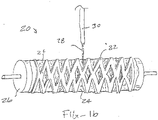
Fig. 1a illustrates an endoluminal prosthesis constructed in accordance with the principles of the present invention. -
Fig. 1b illustrates electrospinning of the second and third sets of fibers over the first set of fibers after a stent has been placed over the first set of fibers. -
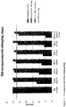
Fig. 1c is a graph showing the outer diameter (OD) of a tested covered stent during crimping and recovery. -
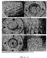
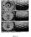
Figs. 2a - 2p are photographs of the tested covered stent during crimping and recovery. -
Fig. 1a illustrates a highlycrimpable device 10 according to the present invention which includes a supportingstent 12 "sandwiched" or laminated between aninner electrospun layer 14 and anouter electrospun layer 16, preferably formed from a biodegradable polymer, such as PTFE, which are fused or bonded together during fabrication as described in detail below. Theinner layer 14 may include integrated semi-lunar leaflets (not illustrated) providing a one-way valve for a prosthetic valve structure. Alternatively, the inner and outer layers of the device may both be generally tubular structures, where the inner layer could serve as a landing zone for a transcatheter (pulmonary) heart valve, which will be deployed in the same or in a separate procedure. Such tubular structures will also find use as grafts for treating aneurysms. Such structures may also find use whenever covered grafts are used in medical procedures. -
Fig. 1b illustrates asystem 20 for electrospinning the second and third sets of fibers over a stent 22 placed on a first set offibers 24 that has been pre-formed into an inner layer over amandrel 26. The outer part of the stent 22 is directly in the line ofpolymer spinning jet 28 directed fromnozzle 30. As the "wet" second set of fibers is applied to the outwardly directed surfaces of the stent 22 and theinner layer 24, there will be some diffusion of the deposited wet fibers to the inside surface of the stent (between the stent and the inner layer) to reinforce the connection and bonding. However, after the wet spinning is completed and the normal spinning started (to form the outer skirt), further bonding is formed through the connection of the inner layer to the outer layer via the wet adhesive or glue layer. - The stents may have any conventional scaffold structure of the type used in medical procedures. The scaffolds may be formed from malleable materials, such as stainless steel, in order to be balloon exapndable. Alternatively, the scaffolds may be formed from elastic materials, such as nickel-titanium alloy, in order to be self-expanding. Particular constructions for both balloon-expandable and self-expanding stents are well known and described in the patent and technical literature.
- By controlling electrospinning and other fabrication conditions, porosity of the outer layer can be controlled to promote cellular in-growth to seal off paravalvular leakage and endovascular leakage. A high porosity of the outer layer or "skirt" also allows the skirt to be relatively thick skirt without compromising valve crimpability.
- The electrospun layers of the present invention preferably comprise supramolecular polymers. Supramolecular polymers are formed when hydrogen bonding units are applied as associating end-groups of bi-functional molecules. The association constants must be sufficiently high to get a high degree of polymerization, which results in real polymer properties. Using supramolecular building blocks that assemble non-covalently via specific interactions, makes it possible to produce materials without tedious synthetic procedures but simply by assembly. In this way, it becomes easy to vary the amount and nature of the bioactive molecules and the nature of the polymers. This supramolecular approach bridges the gap between covalent modification and simple mixing of molecules and polymers. The first method leads to highly stable structures that lack dynamics. The latter, in contrast, results in very dynamic structures that lack stability. Using a supramolecular approach it is possible to control both stability and dynamics. A particular bioactive supramolecular system that we have previously described is based on oligocaprolactone end-functionalized with 2-ureido-4[1H]-pyrimidinone (UPy) groups. These UPy-moieties strongly dimerize via quadruple hydrogen bonding and display high association constants (Ka ¼ 106-107L mol_1) in organic solvents. The UPy-functionalized oligocaprolactone shows much better mechanical properties than its unfunctionalized variation. These supramolecular polymer systems find already many uses in polymer applications.
- Materials and Methods. Pictures were taken from the stent, before, during and after the experiment. Visual inspection was performed at all steps and written down in the study plan. In the study plan it was determined to crimp the stent to 12 mm, 10 mm, 8 mm, 6 mm, 5 mm and maximum possible for 5 minutes at each step. Because it was observed that it was most likely not possible to crimp the stent beyond 5 mm, an extra step of 7 mm was added. The outer diameter (OD) of the stent was measured and written down in the study plan, before crimping, directly after and 5 minutes after each crimping step. After crimping the stent to the maximum step of 5mm, the stent was put into PBS. Pictures were made and the OD was measured at t=0, 5, 10, 15, 20 and 60 minutes. The ID of the sample that was tested was 30.30.080 T2.
- The stents were prepared as follows. A first electrospinning solution was spun over a 29 mm cylindrical target, rotating at 100RPM, to form the inner layer of the covered stent. The solution was an oligocaprolactone-based supramolecular polymer having a 23% polymer concentration and a polymer to solvent (chloroform, hexafluoroisopropanol, and methanol) ratio of 60/40/3. The covered stents were fabricated in a controlled environment of 23° C and 35% relative humidity. After fabrication, the inner layer was removed by soaking it in water (~ 37° C) and using a spatula to physically separate the layer from the metal target. The inner layer was dried at 37° C and under vacuum. The inner layer and the stent were then mounted on a rotating mandrel and aluminum foil was used as a spacer to ensure that the inner layer and the mandrel had good contact. Additional oligocaprolactone-based supramolecular polymer (23% dissolved in chloroform, hexafluoroisopropanol, and methanol - 60/40/3) was electrospun at 9 kV (5 kV, -4 kV) to fabricate the glue/adhesive layer. After applying the glue/adhesive layer, the same solution was electrospun for 20 minutes at 8kV (7 kV, -1 kV) to create the outer layer of the stent.
- Results. The direct recovery of the stent was above 90% for crimping down to 8 mm. After 5 minutes the OD recovery is above 90% for all the crimping steps. This is shown in
figure 1c . Changes to the covered stent as it is crimped and recovered are shown inFigs. 2a - 2p . Visual inspection showed minimal damage to the covered stent for all the crimping steps. Only after the maximum crimping step, two tiny holes appeared in the scaffold (one hole visible inFig. 2n ). The creases in the material become deeper when crimping to a smaller diameter. After putting the stent in pre-heated PBS (37° C), the creases start fading immediately until they are almost gone after 1 hour. Minimal damage of the 30 mm covered stent was observed after 6 crimping steps, with a maximum crimping step of 5 mm. The observed damage was caused by friction between the scaffold and the crimping device. The diameter was able to recover to 96% of the original diameter within 5 minutes after the maximum crimping step. Therefore it can be concluded that the 30 mm covered stent can be crimped to an OD of 5 mm with full recovery and minimal permanent damage. - The foregoing examples are not intended to limit the scope of the invention. All modifications, equivalents and alternatives are within the scope of the invention.
Claims (15)
- A method for electrospinning comprising:(a) providing an electrospinning apparatus comprising:(i) a target,(ii) an applicator in fluid communication with a flowable polymer, said applicator configured to direct a stream of the flowable polymer to the target,(b) applying a first electromotive force on the applicator and a second electromotive force on the target to generate a first electrical potential therebetween;(c) delivering the flowable polymer through the applicator onto the target under first delivery conditions that provide a first flowability while applying a first electrical potential to produce a first set of fibers;(d) adjusting the delivery conditions to provide a second flowability; and(e) delivering the flowable polymer through the applicator onto the target after adjusting the delivery conditions while applying an electrical potential to produce a second set of fibers, wherein said second set of fibers have a substantially flattened cross section.
- The method of claim 1, wherein adjusting the delivery conditions comprises changing at least one of the first and second electromotive forces on the applicator and the target to generate a second electrical potential therebetween.
- The method of claim 1, wherein adjusting the delivery conditions comprises changing a separation distance between the applicator and the target to generate a second electrical potential therebetween.
- The method of claim 1, wherein adjusting the delivery conditions comprises delivering a mixture of at least first and second flowable polymers and adjusting the relative amounts of each flowable polymer to change the flowability of the mixture, optionally wherein delivering the mixture of at least first and second flowable polymers and adjusting the relative amounts of each flowable polymer comprises delivering the at least first and second polymers from at least first and second nozzles and adjusting the amounts being delivered through each nozzle.
- The method of claim 1, wherein the flowable polymer comprises a polymer in a solvent solution and wherein the first set of fibers has a first solvent fraction and the second set of fibers has a second solvent fraction, optionally wherein the second set of fibers has a higher solvent fraction than the first set of fibers so that the second set of fibers can act as an adhesive to a third set of fibers when applied over the second set of fibers.
- The method of claim 5 further comprising:(f) changing at least one of the first and second electromotive forces on the applicator and the target to generate a third electrical potential therebetween; and(g) continuing to deliver the solution through the applicator onto the target to while applying the third electrical potential to produce a third set of fibers having a third solvent fraction over the second set of fibers, wherein the second set of fibers acts as an adhesive between the first and third sets of fibers.
- The method of claim 5 wherein said second set of fibers comprises an amount of the first solvent sufficient to confer flow properties on fibers.
- The method of claim 1 wherein said second set of fibers are ribbon-like.
- The method of claim 1 wherein said second set of fibers have a more flattened cross section on average than the first set of fibers.
- The method of claim 1 wherein the first and second electromotive forces are selected to provide a potential difference in the range between 1 kV and 150 kV, optionally wherein the first electromotive force contributes from 50% to 100%) of the potential difference and the second electromotive force contributes from 0%> to 50%) of the potential difference.
- The method of claim 1 further comprising applying a release agent on the target before delivering the first solution, optionally wherein the release agent comprises one of ethanol and polyethylene-glycol or polyethylene oxide, optionally wherein said release agent is applied by spraying, dipping, painting, or electro spinning.
- The method of claim 11, wherein the release agent is applied by electrospinning with a fourth potential difference between the applicator and the target and delivering the solution through the applicator onto the target to apply the release agent while applying the fourth potential difference.
- The method of claim 11 further comprising rinsing the first set of fibers, with a release agent solvent that at least partially dissolves the release agent to allow the first set of fibers to be removed from the target, optionally wherein the release agent solvent is aqueous.
- The method of claim 1 further comprising rinsing the target with a further solvent after electrospinning to produce the first set of fibers in order to remove the first set of fibers, wherein the further solvent at least partially dissolves the layer containing the target release agent, optionally wherein the further solvent does not dissolve the polymer.
- The method of claim 1 wherein the target comprises a material selected from the group consisting of aluminum, stainless steel, copper, and chromium.
Applications Claiming Priority (2)
| Application Number | Priority Date | Filing Date | Title |
|---|---|---|---|
| US201562236073P | 2015-10-01 | 2015-10-01 | |
| PCT/IB2016/001529 WO2017055926A1 (en) | 2015-10-01 | 2016-10-03 | Methods for electrospin coating and laminating of endoluminal prostheses |
Publications (2)
| Publication Number | Publication Date |
|---|---|
| EP3355949A1 EP3355949A1 (en) | 2018-08-08 |
| EP3355949B1 true EP3355949B1 (en) | 2022-04-20 |
Family
ID=57249837
Family Applications (1)
| Application Number | Title | Priority Date | Filing Date |
|---|---|---|---|
| EP16791670.9A Active EP3355949B1 (en) | 2015-10-01 | 2016-10-03 | Methods for electrospin coating and laminating of endoluminal prostheses |
Country Status (6)
| Country | Link |
|---|---|
| US (1) | US10876222B2 (en) |
| EP (1) | EP3355949B1 (en) |
| JP (1) | JP6829254B2 (en) |
| CN (1) | CN108136078B (en) |
| ES (1) | ES2913723T3 (en) |
| WO (1) | WO2017055926A1 (en) |
Families Citing this family (6)
| Publication number | Priority date | Publication date | Assignee | Title |
|---|---|---|---|---|
| EP3426189B1 (en) * | 2016-03-07 | 2024-01-17 | Boston Scientific Scimed, Inc. | Esophageal stent including a valve member |
| US10953139B2 (en) * | 2017-12-28 | 2021-03-23 | Xeltis Ag | Electro-spun cardiovascular implant |
| PL238746B1 (en) * | 2018-07-24 | 2021-09-27 | American Heart Of Poland Spolka Akcyjna | Method of forming prefabricated elements used in production of transcatheter aortic valve implantation systems |
| CN109248340B (en) * | 2018-09-18 | 2021-04-23 | 武汉纺织大学 | Preparation method of fiber-based artificial blood vessel |
| WO2022101370A1 (en) * | 2020-11-13 | 2022-05-19 | Xeltis Ag | Graft device for endogenous tissue restoration in between two tubular structures |
| CN116059021A (en) * | 2021-12-31 | 2023-05-05 | 元心科技(深圳)有限公司 | Tectorial membrane bracket system and preparation method thereof |
Family Cites Families (22)
| Publication number | Priority date | Publication date | Assignee | Title |
|---|---|---|---|---|
| US6376588B1 (en) * | 1991-10-15 | 2002-04-23 | Huntsman Petrochemical Corporation | Water soluble mold release composition for elastomeric compounds |
| US7244272B2 (en) * | 2000-12-19 | 2007-07-17 | Nicast Ltd. | Vascular prosthesis and method for production thereof |
| US20020084178A1 (en) | 2000-12-19 | 2002-07-04 | Nicast Corporation Ltd. | Method and apparatus for manufacturing polymer fiber shells via electrospinning |
| US20030211135A1 (en) | 2002-04-11 | 2003-11-13 | Greenhalgh Skott E. | Stent having electrospun covering and method |
| JP4496360B2 (en) * | 2003-04-24 | 2010-07-07 | 国立大学法人九州大学 | Medical Polymer Nano / Microfiber |
| WO2006080008A2 (en) | 2005-01-25 | 2006-08-03 | Nicast Ltd. | Artificial vascular prosthesis |
| CN101505687A (en) | 2006-06-21 | 2009-08-12 | 奥尔特克斯公司 | Prosthetic valve implantation systems |
| KR101547800B1 (en) * | 2007-06-26 | 2015-08-26 | 이데미쓰 고산 가부시키가이샤 | Elastic nonwoven fabric, process for producing the same, and textile product comprising the elastic nonwoven fabric |
| US7824601B1 (en) * | 2007-11-14 | 2010-11-02 | Abbott Cardiovascular Systems Inc. | Process of making a tubular implantable medical device |
| US20130268062A1 (en) | 2012-04-05 | 2013-10-10 | Zeus Industrial Products, Inc. | Composite prosthetic devices |
| US20130238086A1 (en) | 2009-01-16 | 2013-09-12 | Zeus Industrial Products, Inc. | Electrospun PTFE Encapsulated Stent & Method of Manufature |
| US8637109B2 (en) | 2009-12-03 | 2014-01-28 | Cook Medical Technologies Llc | Manufacturing methods for covering endoluminal prostheses |
| CN101732117B (en) * | 2009-12-17 | 2012-01-04 | 武汉科技学院 | Bile duct support and preparation method thereof |
| KR101187212B1 (en) * | 2010-12-30 | 2012-10-02 | 주식회사 엠아이텍 | Method for manufacturing drug eluting stent for benign biliary structure using electrospinning |
| DE102011012501A1 (en) * | 2011-02-25 | 2012-08-30 | Phenox Gmbh | Implant with fiber fleece |
| JP5665803B2 (en) | 2011-07-15 | 2015-02-04 | クック メディカル テクノロジーズ エルエルシーCook Medical Technologies Llc | Method for electrospinning a graft layer |
| CN102430157B (en) * | 2011-11-29 | 2013-11-27 | 武汉纺织大学 | Medical scaffold with inner coating film, and preparation method for medical scaffold |
| CN104936671B (en) * | 2012-12-10 | 2018-01-02 | Emd密理博公司 | Super porous nanofiber mat and application thereof |
| US10154918B2 (en) | 2012-12-28 | 2018-12-18 | Cook Medical Technologies Llc | Endoluminal prosthesis with fiber matrix |
| CN103110984A (en) * | 2013-02-20 | 2013-05-22 | 上海典范医疗科技有限公司 | Method for preparing hemostatic polylactic acid anti-adhesion film |
| CN103462726A (en) * | 2013-08-28 | 2013-12-25 | 苏州英络医疗器械有限公司 | Novel covered stent and manufacturing method thereof |
| CN103655015A (en) * | 2013-12-26 | 2014-03-26 | 张建平 | Medicine-carrying nanofiber membrane biliary stent and preparation method thereof |
-
2016
- 2016-10-03 EP EP16791670.9A patent/EP3355949B1/en active Active
- 2016-10-03 US US15/763,197 patent/US10876222B2/en active Active
- 2016-10-03 JP JP2018516441A patent/JP6829254B2/en active Active
- 2016-10-03 ES ES16791670T patent/ES2913723T3/en active Active
- 2016-10-03 CN CN201680057519.0A patent/CN108136078B/en active Active
- 2016-10-03 WO PCT/IB2016/001529 patent/WO2017055926A1/en active Application Filing
Also Published As
| Publication number | Publication date |
|---|---|
| US10876222B2 (en) | 2020-12-29 |
| CN108136078B (en) | 2021-10-12 |
| CN108136078A (en) | 2018-06-08 |
| US20180274131A1 (en) | 2018-09-27 |
| EP3355949A1 (en) | 2018-08-08 |
| WO2017055926A1 (en) | 2017-04-06 |
| JP2018531069A (en) | 2018-10-25 |
| ES2913723T3 (en) | 2022-06-06 |
| JP6829254B2 (en) | 2021-02-10 |
Similar Documents
| Publication | Publication Date | Title |
|---|---|---|
| EP3355949B1 (en) | Methods for electrospin coating and laminating of endoluminal prostheses | |
| JP2018531069A6 (en) | Method for electrospin coating and lamination of endoluminal prostheses | |
| EP1164972B1 (en) | Polymer coated stent | |
| US6156064A (en) | Stent-graft-membrane and method of making the same | |
| EP1093772B1 (en) | Expandable supportive bifurcated endoluminal grafts | |
| US8591564B2 (en) | Hypotube endoluminal device and method | |
| CN109303628B (en) | Soluble or degradable adhesive polymers to prevent stent migration | |
| US9517123B2 (en) | Endovascular prosthesis and a method of connecting a structural component and a woven graft material | |
| EP2779957A2 (en) | Lattice | |
| US11000376B2 (en) | Device and associated percutaneous minimally invasive method for creating a venous valve | |
| US20120029612A1 (en) | Covered toroid stent and methods of manufacture | |
| EP1965731B1 (en) | Endoprosthesis and method of connecting a structural component and a woven graft material | |
| US20180271639A1 (en) | Medical devices for controlled drug release | |
| AU736081B2 (en) | Expandable supportive bifurcated endoluminal grafts |
Legal Events
| Date | Code | Title | Description |
|---|---|---|---|
| STAA | Information on the status of an ep patent application or granted ep patent |
Free format text: STATUS: UNKNOWN |
|
| STAA | Information on the status of an ep patent application or granted ep patent |
Free format text: STATUS: THE INTERNATIONAL PUBLICATION HAS BEEN MADE |
|
| PUAI | Public reference made under article 153(3) epc to a published international application that has entered the european phase |
Free format text: ORIGINAL CODE: 0009012 |
|
| STAA | Information on the status of an ep patent application or granted ep patent |
Free format text: STATUS: REQUEST FOR EXAMINATION WAS MADE |
|
| 17P | Request for examination filed |
Effective date: 20180312 |
|
| AK | Designated contracting states |
Kind code of ref document: A1 Designated state(s): AL AT BE BG CH CY CZ DE DK EE ES FI FR GB GR HR HU IE IS IT LI LT LU LV MC MK MT NL NO PL PT RO RS SE SI SK SM TR |
|
| AX | Request for extension of the european patent |
Extension state: BA ME |
|
| DAV | Request for validation of the european patent (deleted) | ||
| DAX | Request for extension of the european patent (deleted) | ||
| STAA | Information on the status of an ep patent application or granted ep patent |
Free format text: STATUS: EXAMINATION IS IN PROGRESS |
|
| RAP1 | Party data changed (applicant data changed or rights of an application transferred) |
Owner name: NAZ, CHRISTOPHE PIERRE EDOUARD Owner name: XELTIS AG |
|
| 17Q | First examination report despatched |
Effective date: 20200706 |
|
| STAA | Information on the status of an ep patent application or granted ep patent |
Free format text: STATUS: EXAMINATION IS IN PROGRESS |
|
| REG | Reference to a national code |
Ref country code: DE Ref legal event code: R079 Ref document number: 602016071326 Country of ref document: DE Free format text: PREVIOUS MAIN CLASS: A61L0031100000 Ipc: A61L0027340000 |
|
| RIC1 | Information provided on ipc code assigned before grant |
Ipc: D01D 5/00 20060101ALI20211109BHEP Ipc: A61L 31/10 20060101ALI20211109BHEP Ipc: D04H 1/728 20120101ALI20211109BHEP Ipc: A61L 27/34 20060101AFI20211109BHEP |
|
| GRAP | Despatch of communication of intention to grant a patent |
Free format text: ORIGINAL CODE: EPIDOSNIGR1 |
|
| STAA | Information on the status of an ep patent application or granted ep patent |
Free format text: STATUS: GRANT OF PATENT IS INTENDED |
|
| RAP3 | Party data changed (applicant data changed or rights of an application transferred) |
Owner name: XELTIS AG |
|
| INTG | Intention to grant announced |
Effective date: 20211221 |
|
| GRAS | Grant fee paid |
Free format text: ORIGINAL CODE: EPIDOSNIGR3 |
|
| GRAA | (expected) grant |
Free format text: ORIGINAL CODE: 0009210 |
|
| STAA | Information on the status of an ep patent application or granted ep patent |
Free format text: STATUS: THE PATENT HAS BEEN GRANTED |
|
| AK | Designated contracting states |
Kind code of ref document: B1 Designated state(s): AL AT BE BG CH CY CZ DE DK EE ES FI FR GB GR HR HU IE IS IT LI LT LU LV MC MK MT NL NO PL PT RO RS SE SI SK SM TR |
|
| REG | Reference to a national code |
Ref country code: GB Ref legal event code: FG4D |
|
| REG | Reference to a national code |
Ref country code: CH Ref legal event code: EP |
|
| REG | Reference to a national code |
Ref country code: IE Ref legal event code: FG4D |
|
| REG | Reference to a national code |
Ref country code: DE Ref legal event code: R096 Ref document number: 602016071326 Country of ref document: DE |
|
| REG | Reference to a national code |
Ref country code: AT Ref legal event code: REF Ref document number: 1484676 Country of ref document: AT Kind code of ref document: T Effective date: 20220515 |
|
| REG | Reference to a national code |
Ref country code: NL Ref legal event code: FP |
|
| REG | Reference to a national code |
Ref country code: ES Ref legal event code: FG2A Ref document number: 2913723 Country of ref document: ES Kind code of ref document: T3 Effective date: 20220606 |
|
| REG | Reference to a national code |
Ref country code: LT Ref legal event code: MG9D |
|
| REG | Reference to a national code |
Ref country code: AT Ref legal event code: MK05 Ref document number: 1484676 Country of ref document: AT Kind code of ref document: T Effective date: 20220420 |
|
| PG25 | Lapsed in a contracting state [announced via postgrant information from national office to epo] |
Ref country code: SE Free format text: LAPSE BECAUSE OF FAILURE TO SUBMIT A TRANSLATION OF THE DESCRIPTION OR TO PAY THE FEE WITHIN THE PRESCRIBED TIME-LIMIT Effective date: 20220420 Ref country code: PT Free format text: LAPSE BECAUSE OF FAILURE TO SUBMIT A TRANSLATION OF THE DESCRIPTION OR TO PAY THE FEE WITHIN THE PRESCRIBED TIME-LIMIT Effective date: 20220822 Ref country code: NO Free format text: LAPSE BECAUSE OF FAILURE TO SUBMIT A TRANSLATION OF THE DESCRIPTION OR TO PAY THE FEE WITHIN THE PRESCRIBED TIME-LIMIT Effective date: 20220720 Ref country code: LT Free format text: LAPSE BECAUSE OF FAILURE TO SUBMIT A TRANSLATION OF THE DESCRIPTION OR TO PAY THE FEE WITHIN THE PRESCRIBED TIME-LIMIT Effective date: 20220420 Ref country code: HR Free format text: LAPSE BECAUSE OF FAILURE TO SUBMIT A TRANSLATION OF THE DESCRIPTION OR TO PAY THE FEE WITHIN THE PRESCRIBED TIME-LIMIT Effective date: 20220420 Ref country code: GR Free format text: LAPSE BECAUSE OF FAILURE TO SUBMIT A TRANSLATION OF THE DESCRIPTION OR TO PAY THE FEE WITHIN THE PRESCRIBED TIME-LIMIT Effective date: 20220721 Ref country code: FI Free format text: LAPSE BECAUSE OF FAILURE TO SUBMIT A TRANSLATION OF THE DESCRIPTION OR TO PAY THE FEE WITHIN THE PRESCRIBED TIME-LIMIT Effective date: 20220420 Ref country code: BG Free format text: LAPSE BECAUSE OF FAILURE TO SUBMIT A TRANSLATION OF THE DESCRIPTION OR TO PAY THE FEE WITHIN THE PRESCRIBED TIME-LIMIT Effective date: 20220720 Ref country code: AT Free format text: LAPSE BECAUSE OF FAILURE TO SUBMIT A TRANSLATION OF THE DESCRIPTION OR TO PAY THE FEE WITHIN THE PRESCRIBED TIME-LIMIT Effective date: 20220420 |
|
| PG25 | Lapsed in a contracting state [announced via postgrant information from national office to epo] |
Ref country code: RS Free format text: LAPSE BECAUSE OF FAILURE TO SUBMIT A TRANSLATION OF THE DESCRIPTION OR TO PAY THE FEE WITHIN THE PRESCRIBED TIME-LIMIT Effective date: 20220420 Ref country code: PL Free format text: LAPSE BECAUSE OF FAILURE TO SUBMIT A TRANSLATION OF THE DESCRIPTION OR TO PAY THE FEE WITHIN THE PRESCRIBED TIME-LIMIT Effective date: 20220420 Ref country code: LV Free format text: LAPSE BECAUSE OF FAILURE TO SUBMIT A TRANSLATION OF THE DESCRIPTION OR TO PAY THE FEE WITHIN THE PRESCRIBED TIME-LIMIT Effective date: 20220420 Ref country code: IS Free format text: LAPSE BECAUSE OF FAILURE TO SUBMIT A TRANSLATION OF THE DESCRIPTION OR TO PAY THE FEE WITHIN THE PRESCRIBED TIME-LIMIT Effective date: 20220820 |
|
| REG | Reference to a national code |
Ref country code: DE Ref legal event code: R097 Ref document number: 602016071326 Country of ref document: DE |
|
| PG25 | Lapsed in a contracting state [announced via postgrant information from national office to epo] |
Ref country code: SM Free format text: LAPSE BECAUSE OF FAILURE TO SUBMIT A TRANSLATION OF THE DESCRIPTION OR TO PAY THE FEE WITHIN THE PRESCRIBED TIME-LIMIT Effective date: 20220420 Ref country code: SK Free format text: LAPSE BECAUSE OF FAILURE TO SUBMIT A TRANSLATION OF THE DESCRIPTION OR TO PAY THE FEE WITHIN THE PRESCRIBED TIME-LIMIT Effective date: 20220420 Ref country code: RO Free format text: LAPSE BECAUSE OF FAILURE TO SUBMIT A TRANSLATION OF THE DESCRIPTION OR TO PAY THE FEE WITHIN THE PRESCRIBED TIME-LIMIT Effective date: 20220420 Ref country code: EE Free format text: LAPSE BECAUSE OF FAILURE TO SUBMIT A TRANSLATION OF THE DESCRIPTION OR TO PAY THE FEE WITHIN THE PRESCRIBED TIME-LIMIT Effective date: 20220420 Ref country code: DK Free format text: LAPSE BECAUSE OF FAILURE TO SUBMIT A TRANSLATION OF THE DESCRIPTION OR TO PAY THE FEE WITHIN THE PRESCRIBED TIME-LIMIT Effective date: 20220420 Ref country code: CZ Free format text: LAPSE BECAUSE OF FAILURE TO SUBMIT A TRANSLATION OF THE DESCRIPTION OR TO PAY THE FEE WITHIN THE PRESCRIBED TIME-LIMIT Effective date: 20220420 |
|
| PLBE | No opposition filed within time limit |
Free format text: ORIGINAL CODE: 0009261 |
|
| STAA | Information on the status of an ep patent application or granted ep patent |
Free format text: STATUS: NO OPPOSITION FILED WITHIN TIME LIMIT |
|
| 26N | No opposition filed |
Effective date: 20230123 |
|
| PG25 | Lapsed in a contracting state [announced via postgrant information from national office to epo] |
Ref country code: AL Free format text: LAPSE BECAUSE OF FAILURE TO SUBMIT A TRANSLATION OF THE DESCRIPTION OR TO PAY THE FEE WITHIN THE PRESCRIBED TIME-LIMIT Effective date: 20220420 |
|
| PG25 | Lapsed in a contracting state [announced via postgrant information from national office to epo] |
Ref country code: SI Free format text: LAPSE BECAUSE OF FAILURE TO SUBMIT A TRANSLATION OF THE DESCRIPTION OR TO PAY THE FEE WITHIN THE PRESCRIBED TIME-LIMIT Effective date: 20220420 Ref country code: MC Free format text: LAPSE BECAUSE OF FAILURE TO SUBMIT A TRANSLATION OF THE DESCRIPTION OR TO PAY THE FEE WITHIN THE PRESCRIBED TIME-LIMIT Effective date: 20220420 |
|
| PG25 | Lapsed in a contracting state [announced via postgrant information from national office to epo] |
Ref country code: LU Free format text: LAPSE BECAUSE OF NON-PAYMENT OF DUE FEES Effective date: 20221003 |
|
| P01 | Opt-out of the competence of the unified patent court (upc) registered |
Effective date: 20230526 |
|
| PGFP | Annual fee paid to national office [announced via postgrant information from national office to epo] |
Ref country code: NL Payment date: 20231003 Year of fee payment: 8 |
|
| PGFP | Annual fee paid to national office [announced via postgrant information from national office to epo] |
Ref country code: GB Payment date: 20231018 Year of fee payment: 8 |
|
| PGFP | Annual fee paid to national office [announced via postgrant information from national office to epo] |
Ref country code: ES Payment date: 20231201 Year of fee payment: 8 |
|
| PGFP | Annual fee paid to national office [announced via postgrant information from national office to epo] |
Ref country code: IT Payment date: 20231006 Year of fee payment: 8 Ref country code: IE Payment date: 20231018 Year of fee payment: 8 Ref country code: FR Payment date: 20231027 Year of fee payment: 8 Ref country code: DE Payment date: 20231102 Year of fee payment: 8 Ref country code: CH Payment date: 20231102 Year of fee payment: 8 |
|
| PGFP | Annual fee paid to national office [announced via postgrant information from national office to epo] |
Ref country code: BE Payment date: 20231003 Year of fee payment: 8 |
|
| PG25 | Lapsed in a contracting state [announced via postgrant information from national office to epo] |
Ref country code: HU Free format text: LAPSE BECAUSE OF FAILURE TO SUBMIT A TRANSLATION OF THE DESCRIPTION OR TO PAY THE FEE WITHIN THE PRESCRIBED TIME-LIMIT; INVALID AB INITIO Effective date: 20161003 |
|
| PG25 | Lapsed in a contracting state [announced via postgrant information from national office to epo] |
Ref country code: CY Free format text: LAPSE BECAUSE OF FAILURE TO SUBMIT A TRANSLATION OF THE DESCRIPTION OR TO PAY THE FEE WITHIN THE PRESCRIBED TIME-LIMIT Effective date: 20220420 |