EP3354808A1 - Garniture d'évacuation pourvue de bouchon de vidange pouvant être soulevé et abaissé - Google Patents
Garniture d'évacuation pourvue de bouchon de vidange pouvant être soulevé et abaissé Download PDFInfo
- Publication number
- EP3354808A1 EP3354808A1 EP17201983.8A EP17201983A EP3354808A1 EP 3354808 A1 EP3354808 A1 EP 3354808A1 EP 17201983 A EP17201983 A EP 17201983A EP 3354808 A1 EP3354808 A1 EP 3354808A1
- Authority
- EP
- European Patent Office
- Prior art keywords
- drain
- housing
- inlet opening
- guide
- drain plug
- Prior art date
- Legal status (The legal status is an assumption and is not a legal conclusion. Google has not performed a legal analysis and makes no representation as to the accuracy of the status listed.)
- Granted
Links
- 230000005540 biological transmission Effects 0.000 claims abstract description 47
- 125000006850 spacer group Chemical group 0.000 claims description 16
- 238000009434 installation Methods 0.000 abstract description 3
- 239000002699 waste material Substances 0.000 description 14
- XLYOFNOQVPJJNP-UHFFFAOYSA-N water Substances O XLYOFNOQVPJJNP-UHFFFAOYSA-N 0.000 description 8
- 101100493705 Caenorhabditis elegans bath-36 gene Proteins 0.000 description 5
- 230000002093 peripheral effect Effects 0.000 description 3
- 238000007789 sealing Methods 0.000 description 3
- 230000000295 complement effect Effects 0.000 description 2
- 238000003287 bathing Methods 0.000 description 1
- 230000001419 dependent effect Effects 0.000 description 1
- 230000001747 exhibiting effect Effects 0.000 description 1
- 230000002349 favourable effect Effects 0.000 description 1
- 238000004519 manufacturing process Methods 0.000 description 1
- 230000000007 visual effect Effects 0.000 description 1
Images


Classifications
-
- E—FIXED CONSTRUCTIONS
- E03—WATER SUPPLY; SEWERAGE
- E03C—DOMESTIC PLUMBING INSTALLATIONS FOR FRESH WATER OR WASTE WATER; SINKS
- E03C1/00—Domestic plumbing installations for fresh water or waste water; Sinks
- E03C1/12—Plumbing installations for waste water; Basins or fountains connected thereto; Sinks
- E03C1/22—Outlet devices mounted in basins, baths, or sinks
- E03C1/23—Outlet devices mounted in basins, baths, or sinks with mechanical closure mechanisms
- E03C1/2302—Outlet devices mounted in basins, baths, or sinks with mechanical closure mechanisms the actuation force being transmitted to the plug via rigid elements
-
- E—FIXED CONSTRUCTIONS
- E03—WATER SUPPLY; SEWERAGE
- E03C—DOMESTIC PLUMBING INSTALLATIONS FOR FRESH WATER OR WASTE WATER; SINKS
- E03C1/00—Domestic plumbing installations for fresh water or waste water; Sinks
- E03C1/12—Plumbing installations for waste water; Basins or fountains connected thereto; Sinks
- E03C1/26—Object-catching inserts or similar devices for waste pipes or outlets
- E03C1/264—Separate sieves or similar object-catching inserts
Definitions
- the invention relates to a drain fitting, in particular for a bathtub, having a drain housing having an inlet opening, a drain plug for sealingly closing the inlet opening, wherein the drain plug is provided on its underside with at least one guide and force transmission element, and wherein the drain housing a lifting mechanism which acts to lift the drain plug on the guide and power transmission element. Furthermore, the invention relates to a sanitary object in the form of a bathtub with such a drain fitting.
- a sanitary tub assembly with a tub body in the form of a flat shower tray known.
- the tub body has in its bottom an elongated drain opening and a recess surrounding the drain opening.
- a pop-up waste is connected, over which a cover is arranged, which is inserted into the recess of the tub body and has a larger base than the drain opening.
- the cover has a central portion with a slit-shaped water passage opening and a peripheral portion surrounding the central portion edge portion, wherein the cover is supported at the edge portion down on the recess and the drain fitting.
- the drain fitting comprises a drain pot with a siphon insert disposed therein.
- this known drain fitting has no drain plug, so that it is not really suitable for the arrangement of a bathtub.
- an outlet fitting for a bathtub which has a fixable at a bottom passage opening of the tub drain housing and a cover disposed above an inlet opening of the drain housing cover.
- the cover is in the form of a plate-shaped, elongated cover and limited to the tub a circumferential flow gap, can flow through the water to the inlet opening of the drain body.
- the cover is provided with at least two spaced connecting means by which it is releasably secured to the drain fitting. The distance between the at least two connecting means is greater than the width of the cover.
- the drain housing has at least two inlet openings which are covered by the elongated cover.
- valve seat for a raisable and lowerable drain valve body (valve cone) with a valve plate and a downwardly projecting valve stem.
- the valve seat and the valve disk are circular, wherein the valve stem is axially guided in a downwardly projecting hollow pin formed on the valve seat.
- the present invention seeks to provide a drain fitting of the type mentioned above, which is suitable for placement on a non-circular, preferably elongated and / or narrow floor drain opening a tub, especially bathtub and a narrow floor drain opening of the tub yet offers a high drainage performance as well as a reliable drain plug closing function.
- the waste fitting according to the invention is characterized in that the inlet opening of the drain housing one of a circular inlet opening deviating shape, preferably a substantially oval, oblong or rectangular shape, wherein the drain plug has a shape corresponding to the shape of the inlet opening, and wherein the drain plug is mounted against rotation in the drain housing.
- the present invention is based on the idea to provide a waste set with raisable and lowerable drain plug for a tub, especially bathtub, which is adapted to the structural features of an elongated, preferably narrow drainage trough in the tub bottom.
- Conventional drains for baths have a standardized circular inlet opening, which can not be easily combined with an elongated narrow bottom recess and an elongate drain opening formed therein.
- the waste assembly according to the invention can be used for damming water in a bathtub, since the drain fitting has a raisable and lowerable drain plug, which corresponds to the non-circular shape of the inlet opening of the drain fitting.
- the rotationally secure mounting of the drain plug with respect to the inlet opening of the drain fitting is essential for reliable operation of the drain plug.
- the guide and power transmission element of the drain plug is formed shank-shaped and has in cross section a deviating from a circular profile profile, preferably a polygonal profile or at least one radial projection comprehensive profile, wherein in the drain housing a the leadership and Force transmission element receiving and securing against rotation guide is provided.
- the drain plug is provided on its underside with at least two guide and power transmission elements, which are each shaft-shaped and parallel to each other, wherein in the drain housing one or at least two the guide and power transmission elements and the drain plug against rotation securing guides are provided.
- a rotationally secure mounting of the drain plug in the drain fitting can also be achieved, so that a reliable closing of the inlet opening of the drain assembly for stagnation of water in the bathtub can be ensured.
- This embodiment preferably also has a minimal clearance between the at least two guide and power transmission elements and the at least one guide.
- This embodiment further offers the advantage that the guide and power transmission elements can be designed as a simple rotationally symmetrical shafts, resulting in a comparatively smaller component complexity and thus has a favorable effect on the production costs of the drain fitting and the associated drain plug. Furthermore, this embodiment offers the advantage of a particularly high stability of the rotation with a relatively long inlet opening and correspondingly elongated drain plug.
- the guide and power transmission element of the drain plug is formed lever-shaped and pivotally mounted about a substantially horizontal axis of rotation in the drain housing, wherein the axis of rotation is spaced from a passing through the center of the inlet opening vertical axis.
- the drain plug can be pivoted to open the waste set from its closed position to an open position.
- a lever mechanism for actuating the drain plug can be at least partially integrated into the lever-shaped guide and power transmission element of the drain plug. This can save space (space).
- the guide and power transmission element viewed in the direction of the horizontal axis of rotation for example, be designed substantially U-shaped.
- other embodiments, such as a substantially L-shaped lever shape of the guide and power transmission element are possible.
- the drain housing having an elongated, the inlet opening containing plate, wherein in the plate fixing means for fixing the drain housing at the bottom of an elongated trough of a bathtub floor, in which an elongated or oval drainage opening of the bathtub is formed integrated.
- the drain fitting can be connected via the plate by fastening means in a simple manner with the bathtub.
- the inlet opening is thereby completely enclosed by the drain opening formed in the bottom of the trough.
- the attachment means define two points of a straight line which are aligned with the horizontal longitudinal central axis of the inlet opening.
- the integrated in the plate fasteners may be formed, for example in the form of threaded holes or embedded nuts, threaded sleeves or screws associated with complementary connecting means, which are preferably mounted on the inside of the elongated trough of the bathtub floor.
- the plate has on its upper side at least two substantially mutually parallel webs or groups of projections.
- the webs are spaced apart from one another in such a way that the webs can form-fit the underside of the trough formed in the bathtub. As a result, the precise installation of the drain fitting on the bottom of the trough of the bathtub is facilitated.
- an elongate cover which has spacers on its underside.
- the cover bounded with the tub bottom, a drain gap, which is preferably carried out circumferentially.
- the cover is preferably provided or designed as a panel and serves on the one hand to increase the comfort of a user of the bathtub in the same, since the cover of the feeling of a flat seating or lying surface can be taught.
- the cover improves the visual impression of the bathtub in the area of the floor drain.
- the cover is spaced by the spacers from the bottom of the trough, wherein between the cover and the trough, preferably a circumferential annular gap is defined, via which the water in the bathtub can reach the drain or the inlet opening.
- the spacer has ends which are positively and / or non-positively connectable with screw heads.
- the recess formed in the bathtub does not have to have a separate device for fastening the spacers, but the spacers can be fixed to fastening means of the drain housing.
- the fastening means are preferably designed as screws, the screw heads protrude relative to the bottom of the trough and thus positively and / or non-positively connected to the associated spacers, the ends of which have the screw heads receiving recesses or blind holes.
- the spacers at least partially consist of spacers, which are designed in the form of two or more resilient legs.
- the cover can be supported on the bottom of the trough, whereby the stability of the cover is increased. The cover is then held by the elastic legs form-fitting and non-positively in the trough.
- the drain housing has a lower housing part, which defines an odor trap and is provided with a connection for an overflow line, wherein the lower housing part is rotatably connected via a liquid-tight rotary connection with an upper housing part, and wherein the upper housing part, the inlet opening having.
- the present invention relates to a sanitary object in the form of a bathtub, which has in its bottom an elongated trough, in which an oval or elongated drain opening is formed, on which an inventive waste set is set.
- a sanitary object corresponds in terms of its design to the trend to elongated floor drainage openings in shower trays and shower trays, but can be used not only for showering but also for bathing.
- the waste assembly according to the invention allows a high drainage performance, especially if the sanitary object is used for showering, and provides, if the sanitary object is used as a bathtub, a reliable drain plug closing function safely.
- through holes for receiving fastening screws are formed in the bottom of the elongated trough of the bathtub next to the drain opening.
- the drain housing engages around the underside of the trough in a form-fitting manner. In this way, an undesired slipping of the drain fitting against the drain opening in the trough bottom can be reliably prevented.
- this embodiment provides additional stability during assembly of the drain housing and facilitates its assembly, since a preassembly of the drain housing is achieved by the positive gripping the underside of the trough, which is then completed by screwing or tightening the mounting screws.
- Fig. 1 shows a portion of a sanitary object in the form of a bathtub 36 with a drain assembly according to the invention in a perspective view, wherein a cover 24 and a drain plug 6 of the drain fitting are raised explosively.
- the bathtub 36 has in its bottom 38 on an elongated trough 18, in which an elongated, for example, almost rectangular drain opening 20th is trained.
- the corners of the drain opening 20 are preferably rounded (see. Fig. 4 ).
- the drain housing 4 of the drain fitting has an inlet opening 2, which is in the assembled state of the drain fitting in the region of the drain opening 20 of the bathtub.
- the inlet opening 2 of the drain housing 4 is elongated or oval. (see. Fig. 2 and 4 ). Accordingly, the drain plug 6 has an elongated or oval shape.
- the peripheral edge of the drain plug 6 is provided with a groove, is inserted into the sealing ring, so that the drain plug 6, the inlet opening 2 can seal in a reliable manner.
- a guide and power transmission element 8 is arranged at the bottom of the drain plug 6.
- the guide and power transmission element 8 is, for example, cohesively, non-positively or integrally connected to the drain plug 6.
- the guide and power transmission element 8 is designed as a shaft having radial projections and mounted in a corresponding thereto guide 9 against rotation in the drain housing 4.
- the shaft-shaped guide and power transmission element 8 extends substantially vertically.
- the guide 9 assigned to the guide and power transmission element 8 has an internal polygonal profile which, for example, is designed essentially as a hexagon socket profile here.
- the radial projections or ribs of the guide and power transmission element 8 extend along its longitudinal axis.
- At the lower end of the guide and power transmission element 8 may be provided a threaded bore into which an adjusting screw is screwed.
- the guide 9 may have a radially inwardly projecting web which engages with play in a longitudinal groove which is defined by two of the radial projections or ribs of the guide and power transmission element 8.
- the guide 9 ensures that the guide and power transmission element 8 of the drain plug 6 only in one certain position in the guide 9 can be inserted.
- the polygonal profile or cross-sectional shape of the guide 9 and the complementary or form-fitting matching cross-sectional shape of the shaft-shaped guide and power transmission element 8 of the drain plug 6 ensure that the drain plug 6 is mounted against rotation in the drain housing 4 and thus not when raising and lowering about the longitudinal central axis of the shaft-shaped guide and power transmission element 8 rotates. As a result, a reliable closing of the elongated inlet opening 2 is ensured by the elongated drain plug 6 in its lowered position.
- two sleeve-shaped spacers 26 are mounted with lateral elastic legs, so that the cover 24 is secured against tilting and can be positively and stably inserted into the trough 18 of the bath 36.
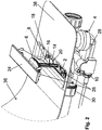
- the cover 24 In the assembled state of the drain fitting, the cover 24 is supported by the spacer 26 in the trough 18 so that it substantially or approximately flush with the surrounding the trough 18 bottom of the bath 36 (see. Fig. 3 ).
- the trough 18 and the cover 24 inserted therein limit thereby a circumferential annular gap 19.
- water to be drained can reach the drain opening 20 of the bathtub 36 and the inlet opening 2 of the drain fitting and drain when the drain plug 6 is open.
- the drain housing 4 comprises a lower housing part 28 and an upper housing part 34, wherein the two housing parts 28 and 34 are connected to each other via a liquid-tight rotary joint 32.
- the lower housing part 28 of the drain housing 4 defines an odor trap and has a connection 30 for an overflow line 31.
- the overflow line 31 is connected to a arranged below the upper edge of the tub overflow opening.
- an operating element 33 for example in the form of a rotating rosette, for actuating a lifting mechanism 10 for raising or lowering the drain plug 6 is arranged.
- the lifting mechanism 10 has, for example, a shaft (not shown), on which a finger-shaped lever is rotatably mounted, the end or tip of which acts on the guide and power transmission element 8 of the drain plug 6.
- a rotational movement of the operating element 33 is transmitted to a Bowden cable via a gear (not shown) arranged in an overflow housing (not shown) fixed to the overflow opening.
- the Bowden cable is connected to a second lever (not shown) of the shaft of the lifting mechanism 10.
- the Figures 2 . 4 and 5 show that the waste fitting has a plate 14 which defines the closable through the drain plug 6 inlet opening 2 of the drain fitting.
- the plate 14 is connected by two fastening means in the form of fastening screws 16 with the underside of the trough 18 of the bath 36.
- a circumferential seal (not shown) is arranged, which surrounds the inlet opening 2 and seals the nip defined by the plate 14 and the underside of the trough 18 against ingress of water.
- the heads of the mounting screws 16 are opposite the bottom 40 of the trough 18 of the bath 36 before.
- the fastening screws 16 form two points of a straight line, which are aligned with the horizontal longitudinal central axis of the oval inlet opening 2.
- the ends of the sleeve-shaped spacers 26 of the cover 24 are fitted positively on the heads of the fastening screws 16.
- the screw heads preferably have an annular groove into which a rubber ring is inserted. The rubber rings cause a frictional connection of the sleeve-shaped spacers 26 with the screw heads.
- Fig. 5 It can be seen that the plate 14 of the drain housing has at its top two substantially mutually parallel webs 22 which engage around the underside of the trough 18 in a form-fitting manner. Through this positive connection, the connection of the drain fitting to the drain opening 20 of the bath 36 is improved.
- Fig. 6 also shows a plate 14 of the drain housing of a drain fitting according to the invention with an elongated or oval inlet opening 2 and a drain plug associated with the inlet opening 6.
- the plate 14 has two mutually parallel webs 22, which are to embrace the underside of the recess formed in the trough bottom 18 form fit.
- the peripheral edge of the drain plug 6 has a circumferential groove with a sealing ring 23 inserted therein, so that the drain plug 6 can seal the elongated or oval inlet opening 2 in a reliable manner.
- the drain plug 6 has on its underside a shaft-shaped guide and power transmission element 8a.
- the guide and power transmission element 8a is configured for example as a hollow, tubular profile with two radial projections or ribs.
- the two projections or ribs point in opposite directions. They are thus offset by approximately 180 ° to each other formed on the tubular profile.
- Fig. 6 an outlined with the bottom of the drain plug 6 guide and power transmission element 8b outlined in the form of a hexagonal hollow profile.
- the associated guide (not shown) has a hexagonal inner profile for the torsion-proof reception of the guide and force transmission element 8b.
- Fig. 7 schematically illustrated embodiment differs from the in Fig. 6 illustrated embodiments in that the non-rotatable mounting of the drain plug 6 in the drain housing not by a polygonal profile or at least one radial projection exhibiting profile, but by two circular cylindrical guide and power transmission elements 8 are realized.
- the drain housing 4 then has at least one elongated guide 9 or two circular guides in cross section, which are connected by positive engagement with the two guide and power transmission elements 8 such that the drain plug 6 relative to the inlet opening 2 of the drain housing not can twist.
- the drain plug 6 has a circumferential sealing ring 23.
- the guide and power transmission element 8 of the drain plug 6 is designed lever-shaped and pivotally mounted about a substantially horizontal axis of rotation 12 in the drain housing 4.
- the guide and power transmission element 8 is U-shaped in the direction of the rotation axis 12, wherein the rotation axis 12 is arranged at a distance from a vertical axis extending through the center of the inlet opening 2.
- the embodiment of the invention is not limited to the embodiments shown in the drawing. On the contrary, numerous variants are conceivable which make use of the invention specified in the appended claims, even if the design deviates from the examples shown.
- the shaft-shaped guide and power transmission element 8 of the elongated or oval drain plug 6 also have a triangular, quadrangular, pentagonal or polygonal cross-sectional profile, the associated guide 9 in the drain housing 4 then has a corresponding inner profile for a twist-proof guiding the drain plug.
- the elongated inlet opening 2 and the elongate drain plug 6 may also be substantially rectangular.
Landscapes
- Engineering & Computer Science (AREA)
- Environmental & Geological Engineering (AREA)
- Health & Medical Sciences (AREA)
- Life Sciences & Earth Sciences (AREA)
- Hydrology & Water Resources (AREA)
- Public Health (AREA)
- Water Supply & Treatment (AREA)
- Mechanical Engineering (AREA)
- Sink And Installation For Waste Water (AREA)
Applications Claiming Priority (1)
| Application Number | Priority Date | Filing Date | Title |
|---|---|---|---|
| DE202017100472.4U DE202017100472U1 (de) | 2017-01-30 | 2017-01-30 | Ablaufgarnitur mit heb- und senkbarem Ablaufstopfen |
Publications (2)
| Publication Number | Publication Date |
|---|---|
| EP3354808A1 true EP3354808A1 (fr) | 2018-08-01 |
| EP3354808B1 EP3354808B1 (fr) | 2020-10-21 |
Family
ID=60382098
Family Applications (1)
| Application Number | Title | Priority Date | Filing Date |
|---|---|---|---|
| EP17201983.8A Active EP3354808B1 (fr) | 2017-01-30 | 2017-11-16 | Garniture d'évacuation pourvue de bouchon de vidange pouvant être soulevé et abaissé |
Country Status (4)
| Country | Link |
|---|---|
| EP (1) | EP3354808B1 (fr) |
| DE (1) | DE202017100472U1 (fr) |
| DK (1) | DK3354808T3 (fr) |
| ES (1) | ES2831382T3 (fr) |
Cited By (2)
| Publication number | Priority date | Publication date | Assignee | Title |
|---|---|---|---|---|
| JP2020183648A (ja) * | 2019-05-07 | 2020-11-12 | 積水ホームテクノ株式会社 | 排水栓装置 |
| JP2021169755A (ja) * | 2020-04-16 | 2021-10-28 | 丸一株式会社 | 遠隔操作式排水栓装置 |
Citations (3)
| Publication number | Priority date | Publication date | Assignee | Title |
|---|---|---|---|---|
| WO1990011414A1 (fr) * | 1989-03-23 | 1990-10-04 | Ideal-Standard Gmbh | Garniture d'ecoulement |
| DE202012103312U1 (de) * | 2012-08-30 | 2013-12-04 | Viega Gmbh & Co. Kg | Ablaufgarnitur für eine sanitäre Wanne oder Duschtasse und dafür hergerichtete sanitäre Wanne oder Duschtasse |
| DE202015101073U1 (de) * | 2015-03-05 | 2015-03-20 | Franz Kaldewei Gmbh & Co. Kg | Sanitärwannenanordnung |
Family Cites Families (3)
| Publication number | Priority date | Publication date | Assignee | Title |
|---|---|---|---|---|
| FR1590603A (fr) * | 1968-05-21 | 1970-04-20 | ||
| DE102005011790B3 (de) * | 2005-03-11 | 2006-11-23 | Franz Kaldewei Gmbh & Co Kg | Sanitärwanne |
| CA2829072C (fr) * | 2013-10-02 | 2020-03-10 | Canplas Industries Ltd. | Necessaire d'evacuation et de trop-plein de baignoire |
-
2017
- 2017-01-30 DE DE202017100472.4U patent/DE202017100472U1/de active Active
- 2017-11-16 DK DK17201983.8T patent/DK3354808T3/da active
- 2017-11-16 EP EP17201983.8A patent/EP3354808B1/fr active Active
- 2017-11-16 ES ES17201983T patent/ES2831382T3/es active Active
Patent Citations (3)
| Publication number | Priority date | Publication date | Assignee | Title |
|---|---|---|---|---|
| WO1990011414A1 (fr) * | 1989-03-23 | 1990-10-04 | Ideal-Standard Gmbh | Garniture d'ecoulement |
| DE202012103312U1 (de) * | 2012-08-30 | 2013-12-04 | Viega Gmbh & Co. Kg | Ablaufgarnitur für eine sanitäre Wanne oder Duschtasse und dafür hergerichtete sanitäre Wanne oder Duschtasse |
| DE202015101073U1 (de) * | 2015-03-05 | 2015-03-20 | Franz Kaldewei Gmbh & Co. Kg | Sanitärwannenanordnung |
Cited By (2)
| Publication number | Priority date | Publication date | Assignee | Title |
|---|---|---|---|---|
| JP2020183648A (ja) * | 2019-05-07 | 2020-11-12 | 積水ホームテクノ株式会社 | 排水栓装置 |
| JP2021169755A (ja) * | 2020-04-16 | 2021-10-28 | 丸一株式会社 | 遠隔操作式排水栓装置 |
Also Published As
| Publication number | Publication date |
|---|---|
| DE202017100472U1 (de) | 2018-05-03 |
| ES2831382T3 (es) | 2021-06-08 |
| DK3354808T3 (da) | 2020-11-09 |
| EP3354808B1 (fr) | 2020-10-21 |
Similar Documents
| Publication | Publication Date | Title |
|---|---|---|
| EP1967665B1 (fr) | Dispositif d'écoulement et de trop-plein pour baignoires | |
| EP2392739A1 (fr) | Egout avec support réglable en hauteur | |
| EP2045403A1 (fr) | Garniture d'ecoulement avec trop-plein intégré | |
| EP3354808B1 (fr) | Garniture d'évacuation pourvue de bouchon de vidange pouvant être soulevé et abaissé | |
| DE2806382A1 (de) | Ueberlaufventil | |
| EP2322729B1 (fr) | Dispositif d'écoulement et de trop-plein, notamment pour baignoires | |
| EP2703573B1 (fr) | Bouche d'égout et bac de douche ou baignoire avec une telle bouche d'égout | |
| EP1002907B1 (fr) | Armature sanitaire et élément de retenue | |
| EP1793052A2 (fr) | Armature d'entrée et de trop-plein pour baignoires | |
| EP0801178B1 (fr) | Bonde de vidange avec tuyau de réglage téléscopique | |
| EP2767638B1 (fr) | Armature d'écoulement et de trop-plein avec régulateur de jet pour baignoires | |
| EP1217130A1 (fr) | Dispositif de fixation pour des parties de robinetterie sanitaire | |
| EP2775047B1 (fr) | Armature d'écoulement et de trop-plein pour baignoire | |
| DE29823021U1 (de) | Ablaufgarnitur für eine Badewanne | |
| EP2119837A1 (fr) | Garniture d'écoulement pour lavabos ou éviers | |
| DE3235970A1 (de) | Ab- und ueberlaufarmatur fuer badewannen, brausewannen od. dgl. | |
| EP0081048A2 (fr) | Dispositif d'écoulement et de trop-plein pour lavabo, bidet ou appareil sanitaire similaire | |
| DE202006012663U1 (de) | Vorrichtung zur Erfassung des Wasserstandes in einem mit einer Ablaufgarnitur versehenen sanitären Becken | |
| EP1001203B1 (fr) | Poignée rotative pour un robinet sanitaire | |
| EP3783158B1 (fr) | Armature d'écoulement et de trop-plein pour une baignoire | |
| EP0499716A1 (fr) | Robinet mélangeur à levier unique pour installations sanitaires | |
| EP2636805B1 (fr) | Lavabo avec un orifice d'évacuation | |
| EP4119737B1 (fr) | Dispositif de retenue en particulier pour l'évacuation des eaux des toitures plates | |
| EP3173540B1 (fr) | Module de fermeture de trou de vidange d'une cuve et procédé de montage d'un tel module | |
| EP3839157A1 (fr) | Robinetterie d'évacuation pour une baignoire sanitaire ou un receveur de douche |
Legal Events
| Date | Code | Title | Description |
|---|---|---|---|
| PUAI | Public reference made under article 153(3) epc to a published international application that has entered the european phase |
Free format text: ORIGINAL CODE: 0009012 |
|
| STAA | Information on the status of an ep patent application or granted ep patent |
Free format text: STATUS: THE APPLICATION HAS BEEN PUBLISHED |
|
| AK | Designated contracting states |
Kind code of ref document: A1 Designated state(s): AL AT BE BG CH CY CZ DE DK EE ES FI FR GB GR HR HU IE IS IT LI LT LU LV MC MK MT NL NO PL PT RO RS SE SI SK SM TR |
|
| AX | Request for extension of the european patent |
Extension state: BA ME |
|
| STAA | Information on the status of an ep patent application or granted ep patent |
Free format text: STATUS: REQUEST FOR EXAMINATION WAS MADE |
|
| 17P | Request for examination filed |
Effective date: 20190129 |
|
| RBV | Designated contracting states (corrected) |
Designated state(s): AL AT BE BG CH CY CZ DE DK EE ES FI FR GB GR HR HU IE IS IT LI LT LU LV MC MK MT NL NO PL PT RO RS SE SI SK SM TR |
|
| STAA | Information on the status of an ep patent application or granted ep patent |
Free format text: STATUS: EXAMINATION IS IN PROGRESS |
|
| 17Q | First examination report despatched |
Effective date: 20191113 |
|
| GRAP | Despatch of communication of intention to grant a patent |
Free format text: ORIGINAL CODE: EPIDOSNIGR1 |
|
| STAA | Information on the status of an ep patent application or granted ep patent |
Free format text: STATUS: GRANT OF PATENT IS INTENDED |
|
| INTG | Intention to grant announced |
Effective date: 20200428 |
|
| GRAJ | Information related to disapproval of communication of intention to grant by the applicant or resumption of examination proceedings by the epo deleted |
Free format text: ORIGINAL CODE: EPIDOSDIGR1 |
|
| STAA | Information on the status of an ep patent application or granted ep patent |
Free format text: STATUS: EXAMINATION IS IN PROGRESS |
|
| GRAS | Grant fee paid |
Free format text: ORIGINAL CODE: EPIDOSNIGR3 |
|
| STAA | Information on the status of an ep patent application or granted ep patent |
Free format text: STATUS: GRANT OF PATENT IS INTENDED |
|
| GRAJ | Information related to disapproval of communication of intention to grant by the applicant or resumption of examination proceedings by the epo deleted |
Free format text: ORIGINAL CODE: EPIDOSDIGR1 |
|
| GRAL | Information related to payment of fee for publishing/printing deleted |
Free format text: ORIGINAL CODE: EPIDOSDIGR3 |
|
| GRAP | Despatch of communication of intention to grant a patent |
Free format text: ORIGINAL CODE: EPIDOSNIGR1 |
|
| GRAS | Grant fee paid |
Free format text: ORIGINAL CODE: EPIDOSNIGR3 |
|
| STAA | Information on the status of an ep patent application or granted ep patent |
Free format text: STATUS: EXAMINATION IS IN PROGRESS |
|
| GRAR | Information related to intention to grant a patent recorded |
Free format text: ORIGINAL CODE: EPIDOSNIGR71 |
|
| STAA | Information on the status of an ep patent application or granted ep patent |
Free format text: STATUS: GRANT OF PATENT IS INTENDED |
|
| GRAA | (expected) grant |
Free format text: ORIGINAL CODE: 0009210 |
|
| STAA | Information on the status of an ep patent application or granted ep patent |
Free format text: STATUS: THE PATENT HAS BEEN GRANTED |
|
| INTC | Intention to grant announced (deleted) | ||
| INTG | Intention to grant announced |
Effective date: 20200917 |
|
| AK | Designated contracting states |
Kind code of ref document: B1 Designated state(s): AL AT BE BG CH CY CZ DE DK EE ES FI FR GB GR HR HU IE IS IT LI LT LU LV MC MK MT NL NO PL PT RO RS SE SI SK SM TR |
|
| INTG | Intention to grant announced |
Effective date: 20200914 |
|
| REG | Reference to a national code |
Ref country code: GB Ref legal event code: FG4D Free format text: NOT ENGLISH |
|
| REG | Reference to a national code |
Ref country code: CH Ref legal event code: EP |
|
| REG | Reference to a national code |
Ref country code: DE Ref legal event code: R096 Ref document number: 502017007822 Country of ref document: DE |
|
| REG | Reference to a national code |
Ref country code: DK Ref legal event code: T3 Effective date: 20201104 |
|
| REG | Reference to a national code |
Ref country code: IE Ref legal event code: FG4D Free format text: LANGUAGE OF EP DOCUMENT: GERMAN |
|
| REG | Reference to a national code |
Ref country code: CH Ref legal event code: NV Representative=s name: SCHMAUDER AND PARTNER AG PATENT- UND MARKENANW, CH |
|
| REG | Reference to a national code |
Ref country code: AT Ref legal event code: REF Ref document number: 1325997 Country of ref document: AT Kind code of ref document: T Effective date: 20201115 |
|
| REG | Reference to a national code |
Ref country code: NL Ref legal event code: FP |
|
| PG25 | Lapsed in a contracting state [announced via postgrant information from national office to epo] |
Ref country code: FI Free format text: LAPSE BECAUSE OF FAILURE TO SUBMIT A TRANSLATION OF THE DESCRIPTION OR TO PAY THE FEE WITHIN THE PRESCRIBED TIME-LIMIT Effective date: 20201021 Ref country code: GR Free format text: LAPSE BECAUSE OF FAILURE TO SUBMIT A TRANSLATION OF THE DESCRIPTION OR TO PAY THE FEE WITHIN THE PRESCRIBED TIME-LIMIT Effective date: 20210122 Ref country code: NO Free format text: LAPSE BECAUSE OF FAILURE TO SUBMIT A TRANSLATION OF THE DESCRIPTION OR TO PAY THE FEE WITHIN THE PRESCRIBED TIME-LIMIT Effective date: 20210121 Ref country code: RS Free format text: LAPSE BECAUSE OF FAILURE TO SUBMIT A TRANSLATION OF THE DESCRIPTION OR TO PAY THE FEE WITHIN THE PRESCRIBED TIME-LIMIT Effective date: 20201021 Ref country code: PT Free format text: LAPSE BECAUSE OF FAILURE TO SUBMIT A TRANSLATION OF THE DESCRIPTION OR TO PAY THE FEE WITHIN THE PRESCRIBED TIME-LIMIT Effective date: 20210222 |
|
| REG | Reference to a national code |
Ref country code: LT Ref legal event code: MG4D |
|
| PG25 | Lapsed in a contracting state [announced via postgrant information from national office to epo] |
Ref country code: PL Free format text: LAPSE BECAUSE OF FAILURE TO SUBMIT A TRANSLATION OF THE DESCRIPTION OR TO PAY THE FEE WITHIN THE PRESCRIBED TIME-LIMIT Effective date: 20201021 Ref country code: IS Free format text: LAPSE BECAUSE OF FAILURE TO SUBMIT A TRANSLATION OF THE DESCRIPTION OR TO PAY THE FEE WITHIN THE PRESCRIBED TIME-LIMIT Effective date: 20210221 Ref country code: LV Free format text: LAPSE BECAUSE OF FAILURE TO SUBMIT A TRANSLATION OF THE DESCRIPTION OR TO PAY THE FEE WITHIN THE PRESCRIBED TIME-LIMIT Effective date: 20201021 Ref country code: BG Free format text: LAPSE BECAUSE OF FAILURE TO SUBMIT A TRANSLATION OF THE DESCRIPTION OR TO PAY THE FEE WITHIN THE PRESCRIBED TIME-LIMIT Effective date: 20210121 Ref country code: SE Free format text: LAPSE BECAUSE OF FAILURE TO SUBMIT A TRANSLATION OF THE DESCRIPTION OR TO PAY THE FEE WITHIN THE PRESCRIBED TIME-LIMIT Effective date: 20201021 |
|
| REG | Reference to a national code |
Ref country code: ES Ref legal event code: FG2A Ref document number: 2831382 Country of ref document: ES Kind code of ref document: T3 Effective date: 20210608 |
|
| PG25 | Lapsed in a contracting state [announced via postgrant information from national office to epo] |
Ref country code: HR Free format text: LAPSE BECAUSE OF FAILURE TO SUBMIT A TRANSLATION OF THE DESCRIPTION OR TO PAY THE FEE WITHIN THE PRESCRIBED TIME-LIMIT Effective date: 20201021 |
|
| REG | Reference to a national code |
Ref country code: DE Ref legal event code: R097 Ref document number: 502017007822 Country of ref document: DE |
|
| PG25 | Lapsed in a contracting state [announced via postgrant information from national office to epo] |
Ref country code: SK Free format text: LAPSE BECAUSE OF FAILURE TO SUBMIT A TRANSLATION OF THE DESCRIPTION OR TO PAY THE FEE WITHIN THE PRESCRIBED TIME-LIMIT Effective date: 20201021 Ref country code: RO Free format text: LAPSE BECAUSE OF FAILURE TO SUBMIT A TRANSLATION OF THE DESCRIPTION OR TO PAY THE FEE WITHIN THE PRESCRIBED TIME-LIMIT Effective date: 20201021 Ref country code: SM Free format text: LAPSE BECAUSE OF FAILURE TO SUBMIT A TRANSLATION OF THE DESCRIPTION OR TO PAY THE FEE WITHIN THE PRESCRIBED TIME-LIMIT Effective date: 20201021 Ref country code: EE Free format text: LAPSE BECAUSE OF FAILURE TO SUBMIT A TRANSLATION OF THE DESCRIPTION OR TO PAY THE FEE WITHIN THE PRESCRIBED TIME-LIMIT Effective date: 20201021 Ref country code: CZ Free format text: LAPSE BECAUSE OF FAILURE TO SUBMIT A TRANSLATION OF THE DESCRIPTION OR TO PAY THE FEE WITHIN THE PRESCRIBED TIME-LIMIT Effective date: 20201021 Ref country code: MC Free format text: LAPSE BECAUSE OF FAILURE TO SUBMIT A TRANSLATION OF THE DESCRIPTION OR TO PAY THE FEE WITHIN THE PRESCRIBED TIME-LIMIT Effective date: 20201021 Ref country code: LU Free format text: LAPSE BECAUSE OF NON-PAYMENT OF DUE FEES Effective date: 20201116 Ref country code: LT Free format text: LAPSE BECAUSE OF FAILURE TO SUBMIT A TRANSLATION OF THE DESCRIPTION OR TO PAY THE FEE WITHIN THE PRESCRIBED TIME-LIMIT Effective date: 20201021 |
|
| REG | Reference to a national code |
Ref country code: BE Ref legal event code: MM Effective date: 20201130 |
|
| PLBE | No opposition filed within time limit |
Free format text: ORIGINAL CODE: 0009261 |
|
| STAA | Information on the status of an ep patent application or granted ep patent |
Free format text: STATUS: NO OPPOSITION FILED WITHIN TIME LIMIT |
|
| 26N | No opposition filed |
Effective date: 20210722 |
|
| PG25 | Lapsed in a contracting state [announced via postgrant information from national office to epo] |
Ref country code: AL Free format text: LAPSE BECAUSE OF FAILURE TO SUBMIT A TRANSLATION OF THE DESCRIPTION OR TO PAY THE FEE WITHIN THE PRESCRIBED TIME-LIMIT Effective date: 20201021 Ref country code: IE Free format text: LAPSE BECAUSE OF NON-PAYMENT OF DUE FEES Effective date: 20201116 |
|
| PG25 | Lapsed in a contracting state [announced via postgrant information from national office to epo] |
Ref country code: SI Free format text: LAPSE BECAUSE OF FAILURE TO SUBMIT A TRANSLATION OF THE DESCRIPTION OR TO PAY THE FEE WITHIN THE PRESCRIBED TIME-LIMIT Effective date: 20201021 |
|
| PG25 | Lapsed in a contracting state [announced via postgrant information from national office to epo] |
Ref country code: IS Free format text: LAPSE BECAUSE OF FAILURE TO SUBMIT A TRANSLATION OF THE DESCRIPTION OR TO PAY THE FEE WITHIN THE PRESCRIBED TIME-LIMIT Effective date: 20210221 Ref country code: TR Free format text: LAPSE BECAUSE OF FAILURE TO SUBMIT A TRANSLATION OF THE DESCRIPTION OR TO PAY THE FEE WITHIN THE PRESCRIBED TIME-LIMIT Effective date: 20201021 Ref country code: MT Free format text: LAPSE BECAUSE OF FAILURE TO SUBMIT A TRANSLATION OF THE DESCRIPTION OR TO PAY THE FEE WITHIN THE PRESCRIBED TIME-LIMIT Effective date: 20201021 Ref country code: CY Free format text: LAPSE BECAUSE OF FAILURE TO SUBMIT A TRANSLATION OF THE DESCRIPTION OR TO PAY THE FEE WITHIN THE PRESCRIBED TIME-LIMIT Effective date: 20201021 |
|
| PG25 | Lapsed in a contracting state [announced via postgrant information from national office to epo] |
Ref country code: MK Free format text: LAPSE BECAUSE OF FAILURE TO SUBMIT A TRANSLATION OF THE DESCRIPTION OR TO PAY THE FEE WITHIN THE PRESCRIBED TIME-LIMIT Effective date: 20201021 |
|
| PG25 | Lapsed in a contracting state [announced via postgrant information from national office to epo] |
Ref country code: BE Free format text: LAPSE BECAUSE OF NON-PAYMENT OF DUE FEES Effective date: 20201130 |
|
| PGFP | Annual fee paid to national office [announced via postgrant information from national office to epo] |
Ref country code: NL Payment date: 20221122 Year of fee payment: 6 Ref country code: GB Payment date: 20221122 Year of fee payment: 6 Ref country code: DK Payment date: 20221125 Year of fee payment: 6 |
|
| REG | Reference to a national code |
Ref country code: AT Ref legal event code: MM01 Ref document number: 1325997 Country of ref document: AT Kind code of ref document: T Effective date: 20221116 |
|
| PGFP | Annual fee paid to national office [announced via postgrant information from national office to epo] |
Ref country code: ES Payment date: 20231222 Year of fee payment: 7 |
|
| PG25 | Lapsed in a contracting state [announced via postgrant information from national office to epo] |
Ref country code: AT Free format text: LAPSE BECAUSE OF NON-PAYMENT OF DUE FEES Effective date: 20221116 |
|
| PGFP | Annual fee paid to national office [announced via postgrant information from national office to epo] |
Ref country code: IT Payment date: 20231122 Year of fee payment: 7 Ref country code: FR Payment date: 20231121 Year of fee payment: 7 Ref country code: DE Payment date: 20231121 Year of fee payment: 7 Ref country code: CH Payment date: 20231201 Year of fee payment: 7 |
|
| REG | Reference to a national code |
Ref country code: DK Ref legal event code: EBP Effective date: 20231130 |
|
| REG | Reference to a national code |
Ref country code: NL Ref legal event code: MM Effective date: 20231201 |
|
| GBPC | Gb: european patent ceased through non-payment of renewal fee |
Effective date: 20231116 |
|
| PG25 | Lapsed in a contracting state [announced via postgrant information from national office to epo] |
Ref country code: NL Free format text: LAPSE BECAUSE OF NON-PAYMENT OF DUE FEES Effective date: 20231201 |