EP3354571A1 - Luftfahrzeugsitz, der mit einer in die sitzwanne integrierten energieabsorptionszone ausgestattet ist - Google Patents
Luftfahrzeugsitz, der mit einer in die sitzwanne integrierten energieabsorptionszone ausgestattet ist Download PDFInfo
- Publication number
- EP3354571A1 EP3354571A1 EP17189545.1A EP17189545A EP3354571A1 EP 3354571 A1 EP3354571 A1 EP 3354571A1 EP 17189545 A EP17189545 A EP 17189545A EP 3354571 A1 EP3354571 A1 EP 3354571A1
- Authority
- EP
- European Patent Office
- Prior art keywords
- seat
- tub
- energy absorption
- zone
- absorption zone
- Prior art date
- Legal status (The legal status is an assumption and is not a legal conclusion. Google has not performed a legal analysis and makes no representation as to the accuracy of the status listed.)
- Granted
Links
Images


Classifications
-
- B—PERFORMING OPERATIONS; TRANSPORTING
- B64—AIRCRAFT; AVIATION; COSMONAUTICS
- B64D—EQUIPMENT FOR FITTING IN OR TO AIRCRAFT; FLIGHT SUITS; PARACHUTES; ARRANGEMENT OR MOUNTING OF POWER PLANTS OR PROPULSION TRANSMISSIONS IN AIRCRAFT
- B64D11/00—Passenger or crew accommodation; Flight-deck installations not otherwise provided for
- B64D11/06—Arrangements of seats, or adaptations or details specially adapted for aircraft seats
- B64D11/0619—Arrangements of seats, or adaptations or details specially adapted for aircraft seats with energy absorbing means specially adapted for mitigating impact loads for passenger seats, e.g. at a crash
-
- B—PERFORMING OPERATIONS; TRANSPORTING
- B60—VEHICLES IN GENERAL
- B60N—SEATS SPECIALLY ADAPTED FOR VEHICLES; VEHICLE PASSENGER ACCOMMODATION NOT OTHERWISE PROVIDED FOR
- B60N2/00—Seats specially adapted for vehicles; Arrangement or mounting of seats in vehicles
- B60N2/24—Seats specially adapted for vehicles; Arrangement or mounting of seats in vehicles for particular purposes or particular vehicles
- B60N2/42—Seats specially adapted for vehicles; Arrangement or mounting of seats in vehicles for particular purposes or particular vehicles the seat constructed to protect the occupant from the effect of abnormal g-forces, e.g. crash or safety seats
- B60N2/4207—Seats specially adapted for vehicles; Arrangement or mounting of seats in vehicles for particular purposes or particular vehicles the seat constructed to protect the occupant from the effect of abnormal g-forces, e.g. crash or safety seats characterised by the direction of the g-forces
- B60N2/4242—Seats specially adapted for vehicles; Arrangement or mounting of seats in vehicles for particular purposes or particular vehicles the seat constructed to protect the occupant from the effect of abnormal g-forces, e.g. crash or safety seats characterised by the direction of the g-forces vertical
-
- B—PERFORMING OPERATIONS; TRANSPORTING
- B60—VEHICLES IN GENERAL
- B60N—SEATS SPECIALLY ADAPTED FOR VEHICLES; VEHICLE PASSENGER ACCOMMODATION NOT OTHERWISE PROVIDED FOR
- B60N2/00—Seats specially adapted for vehicles; Arrangement or mounting of seats in vehicles
- B60N2/24—Seats specially adapted for vehicles; Arrangement or mounting of seats in vehicles for particular purposes or particular vehicles
- B60N2/42—Seats specially adapted for vehicles; Arrangement or mounting of seats in vehicles for particular purposes or particular vehicles the seat constructed to protect the occupant from the effect of abnormal g-forces, e.g. crash or safety seats
- B60N2/427—Seats or parts thereof displaced during a crash
- B60N2/42709—Seats or parts thereof displaced during a crash involving residual deformation or fracture of the structure
-
- B—PERFORMING OPERATIONS; TRANSPORTING
- B60—VEHICLES IN GENERAL
- B60N—SEATS SPECIALLY ADAPTED FOR VEHICLES; VEHICLE PASSENGER ACCOMMODATION NOT OTHERWISE PROVIDED FOR
- B60N2/00—Seats specially adapted for vehicles; Arrangement or mounting of seats in vehicles
- B60N2/68—Seat frames
- B60N2/686—Panel like structures
Definitions
- the present invention relates to an aircraft seat with an integrated energy absorption zone in the tub.
- the invention finds a particularly advantageous application, but not exclusive, with helicopter seats of the single-seater or multi-seat type.
- the helicopter seat may be a pilot seat or a passenger seat.
- the existing helicopter seats 1 generally comprise a tub 2 having a wall forming a seat 3 and a backrest 4.
- a connecting device 5 ensures the connection of the tub 2 to a structural element of the helicopter, such as the floor or the partition.
- the connecting device 5 may include uprights 6 provided with a locking system 7 of the seat with the structural element.
- An energy absorber 8 is generally interposed between the connecting device 5 and the uprights 6. The tub 2 slides along the uprights 6 via the pins 9.
- the energy absorption system 8 also constitutes a dissociated function of the seat function and therefore requires the integration of reported components dedicated to its function.
- the invention thus makes it possible, by integrating the energy absorber into the tub, to reduce the number of parts constituting the seat and thus to reduce the mass of the assembly.
- the invention also increases the free space under the seat, thus reducing the height of the seat without impacting the safety of the occupant in case of crash, or increase the storage space.
- the invention also makes it possible to limit, or even eliminate, the submarine phenomenon in the event of a downward crash linked to the deformation of the energy absorption zone.
- the invention makes it possible to eliminate the harmful effects of floor deformations or of various coefficients of friction introduced by auxiliary slide systems that activate the energy absorber.
- the invention allows to adapt to the weight of the occupant and is effective from the 5th to the 95th percentile without prior action thereof.
- the energy absorption zone is integrated in the back of the tub.
- a second energy absorption zone is integrated in the seat so as to define a hinge zone between the two energy absorption zones. This facilitates the deformation of the bucket during the shock and therefore increases the absorption capacity of the seat.
- the tub comprises means for guiding the energy absorption zone during its stretching.
- a clearance zone is provided under the seat to allow the stretching of the energy absorption zone during an impact.
- the energy absorption zone has a plurality of holes made in the wall of the tub.
- the energy absorbing zone has a plurality of staggered lines of holes, the holes of a given line being between two holes of an adjacent line.
- the energy absorption zone has a first portion and a second portion having holes of different dimensions.
- the energy absorption zone comprises serpentine shapes made in vertical strips.
- the energy absorption zone comprises a band incorporating the repetition of a pattern, in particular of fractal type, in which centrally perforated diamond shapes are positioned at the transverse ends of two larger open diamonds. .
- the energy absorption zone comprises a plurality of vertical strips separated from each other by a space, each vertical strip having alternating curved portions provided with a hole and connecting portions providing a connection between two portions. successive bulges, the curved portions of a given band being located between the curved portions of an adjacent band.
- the energy absorption zone is formed by a part of the tub made of an embossed material.
- the embossed material present, in a vertical direction, an alternation of peaks and valleys to allow the deployment of the folder in case of crash while absorbing energy stretching of the embossed portion.
- the energy absorption zone comprises at least two folds made in the file in two opposite directions, so that parts of the folder are superimposed relative to each other.
- the superimposed portions of the backrest are held together by means of at least one fusible seam.
- the pleats are made in a draping of a composite tub.
- a visual indicator is integrated in the energy absorption zone to check its integrity.
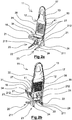
- the Figures 2a, 2b , 3a, 3b show an aircraft seat 11, in particular a helicopter, comprising a tub 12 having a wall 13 forming a seat 16 and a backrest 17.
- the seat 16 is made of material with the backrest 17, that is to say that is, the seat 16 is integral with the backrest 17.
- the two parts 16, 17 can thus be made from the same wall 13 molded or machined.
- the tub 12 may be made of a composite material or sheet metal, for example steel.
- a connecting device 20 provides a mechanical connection between the bucket 12 and a structural element of the aircraft, such as the floor or a transverse partition.
- the connecting device 20 comprises two uprights 21 and crosspieces 22 providing a mechanical connection between the uprights 21.
- Each upright 21, having an L shape, has a first lower portion 211 extending horizontally and a second upper portion 212 extending vertically.
- a locking system 23 makes it possible to lock the seat 11 with the structural element of the aircraft.
- This locking system 23 may comprise fasteners 24 carried by the lower portions 211 to ensure a clamping of the uprights 21 on rails arranged along the floor of the aircraft.
- the bucket 12 is fixed to the uprights 21 by means of fasteners 27, such as bolts, providing a mechanical connection between a support frame 30 carrying the bucket 12 and the lateral face of the upper vertical portions 212 of the uprights 21.
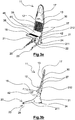
- the external surfaces of the seat 16 and the backrest 17 may be covered with a set of cushions 31 shown on the Figures 2a and 2b .
- a set of cushions 31 shown on the Figures 2a and 2b For a configuration of the seat 11 of the "pilot" type, it will be possible to install longitudinal and vertical adjustment systems of the seat 11 (not shown).
- an occupant restraint system 34 comprising a seat belt provided, in a so-called Y configuration with a single reel 35 or a live configuration (not Y) with two separate reels, of two straps extending around the body of the passenger or pilot and two straps enclosing the passenger's shoulders.
- the backrest 17 of the tub 12 incorporates an energy absorption zone 38 to absorb the energy dissipated by the occupant in the event of a downward impact.
- This energy absorption zone 38 is able to deform by stretching, so as to allow a relative displacement of the seat 16 of the tub 12 with respect to the backrest 17 of the tub 12 during a shock.
- the energy absorption zone 38 may be integrated on the bucket 12 during its manufacture.
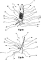
- the seat part 16 moves downwards as a result of the stretching of the material in the energy absorption zone 38.
- the energy absorption zone 38 may for example comprise a plurality of holes 41 for locally weaken the material of the bucket 12, as described in more detail below.
- a clearance zone 42 is provided under the seat 16 to allow the stretching of the energy absorption zone 38 during an impact.
- the clearance zone 42 may be formed by a curved shape of the support frame 30 of the tub 12 which is open towards the seat 16.
- the guiding means 45 may for example take the form of grooves in which the edges of the back 17 slide when the energy absorption zone 38 is stretched.
- a second energy absorption zone 38 may be integrated into the seat 16 so as to define a hinge zone 48 between the two energy absorption zones 38 integrated respectively with the seat 16 and the backrest 17.
- the hinge zone 48 visible in particular on the figures 3a and 4a , corresponds to the portion of the wall 13 having a rounded shape for the connection between the seat 16 and the backrest 17. This facilitates the deformation of the bucket 12 during the shock and therefore increases the energy absorption capacity of the seat 11 .
- a visual indicator 49 may be integrated with the energy absorption zone 38 to verify its integrity.
- the visual indicator 49 may for example take the form of a fuse.
- the energy absorption zone 38 has a lattice configuration in which a plurality of holes 41 are formed side by side in the wall 13 of the tub 12.
- the mesh of the mesh is dimensioned in such a way that the absorber of energy can cover an occupant of the 5th percentile woman to the 95th percentile male.
- the energy absorption zone 38 may thus comprise a plurality of rows 51 of holes 41 staggered, the holes 41 of a given line being located between two holes 41 of an adjacent horizontal line.
- the holes 41 may for example take a diamond shape.
- the energy absorption zone 38 has a first portion 54 and a second lattice portion 55 having different dimensions of holes 41.
- the holes 41 of the portion 55 are larger than those of the part 54.
- the energy absorbing zone 38 comprises serpentine shapes made in vertical strips 57 spaced apart from each other.
- the vertical strips 57 for example three in number, may each comprise two parts 58 in the form of a symmetrical coil around a line 59 of through holes.
- the energy absorbing zone 38 comprises a band 61 incorporating the repetition of a fractal-type pattern in which centrally holed diamond shapes 62 are positioned at the transverse ends of two larger open diamonds.
- the energy absorption zone 38 comprises a plurality of vertical strips 65 separated from each other by a space 66, each vertical strip 65 having an alternation of curved portions 67 provided with a hole 41 and connecting portions 68 ensuring connection between two successive convex portions 67.
- the curved portions 67 of a given band 65 are located between the curved portions 67 of an adjacent band 65.
- the connecting portions 68 follow the curvature of the curved portions 67 of the adjacent strip 65.
- the strips 65 have complementary shapes.
- a height of the strips 65 decreases when moving from one edge to the center of the backrest 17.
- the configuration is substantially symmetrical with respect to a vertical median plane of the backrest 17.
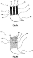
- a portion 69 of the back 17 is made of a material embossed to form the energy absorption zone 38.
- the material has, in a vertical direction, an alternation of vertices 71 and recesses 72 to allow the deployment of the backrest 17 in case of crash while absorbing energy stretching of the embossed portion 69.
- the energy absorption zone 38 comprises at least two folds 75 made in the file 17 in two opposite directions, so that parts 76 of the file 17 are superimposed relative to each other.
- the superimposed portions 76 of the backrest 17 can be held together by means of fusible seams 77.
- the rupture of the seams 77 makes it possible to absorb energy and to allow the seat 16 to move relative to the backrest 17 following unfolding. of the file 17.
- the folds 75 are made in a draping of a tub 12 made of a composite material.
- An energy absorbing zone 38 is integrated during the draping of the composite tub 12. The principle of absorption consists of controlling the delamination between the two composite plies 75 in the event of a vertical crash.
Landscapes
- Engineering & Computer Science (AREA)
- Aviation & Aerospace Engineering (AREA)
- Transportation (AREA)
- Mechanical Engineering (AREA)
- Seats For Vehicles (AREA)
Applications Claiming Priority (1)
| Application Number | Priority Date | Filing Date | Title |
|---|---|---|---|
| FR1670502A FR3055611B1 (fr) | 2016-09-08 | 2016-09-08 | Siege d'aeronef muni d'une zone d'absorption d'energie integree dans le baquet |
Publications (3)
| Publication Number | Publication Date |
|---|---|
| EP3354571A1 true EP3354571A1 (de) | 2018-08-01 |
| EP3354571B1 EP3354571B1 (de) | 2020-10-28 |
| EP3354571B8 EP3354571B8 (de) | 2020-12-30 |
Family
ID=57286734
Family Applications (1)
| Application Number | Title | Priority Date | Filing Date |
|---|---|---|---|
| EP17189545.1A Active EP3354571B8 (de) | 2016-09-08 | 2017-09-06 | Luftfahrzeugsitz, der mit einer in die sitzwanne integrierten energieabsorptionszone ausgestattet ist |
Country Status (2)
| Country | Link |
|---|---|
| EP (1) | EP3354571B8 (de) |
| FR (1) | FR3055611B1 (de) |
Cited By (1)
| Publication number | Priority date | Publication date | Assignee | Title |
|---|---|---|---|---|
| US12139096B2 (en) | 2022-08-04 | 2024-11-12 | B/E Aerospace, Inc. | Rotary lap belt shackle assembly |
Families Citing this family (1)
| Publication number | Priority date | Publication date | Assignee | Title |
|---|---|---|---|---|
| KR102721260B1 (ko) * | 2022-10-05 | 2024-10-23 | (주)에이엔에이치스트럭쳐 | 충격 흡수 장치를 구비한 uam 좌석 |
Citations (8)
| Publication number | Priority date | Publication date | Assignee | Title |
|---|---|---|---|---|
| US4204657A (en) * | 1978-06-30 | 1980-05-27 | Graham Edward F | Life and weight saving aircraft seat structure |
| FR2445244A1 (fr) * | 1978-12-27 | 1980-07-25 | Tachikawa Spring Co | Element de siege pour vehicule |
| WO1992006003A1 (en) * | 1990-09-28 | 1992-04-16 | H.W. Structures Limited | A seat assembly |
| JP2011078557A (ja) * | 2009-10-07 | 2011-04-21 | Toyota Boshoku Corp | 車両用シートバック |
| US20130229038A1 (en) * | 2010-11-17 | 2013-09-05 | Vital Seating & Systems Limited | Seat for absorbing a force |
| US20140015290A1 (en) * | 2011-03-30 | 2014-01-16 | Expliseat | Airplane Seat Provided with a Reinforcing Strip for Absorbing Impacts |
| EP2769916A2 (de) * | 2013-02-25 | 2014-08-27 | PAC Seating Systems, Inc. | Flugzeugsitzenergieabsorbierende Vorrichtung zur Insassenzurückhaltung |
| FR3021918A1 (fr) * | 2014-06-04 | 2015-12-11 | Faurecia Sieges Automobile | Structure de dossier pour siege de vehicule automobile |
-
2016
- 2016-09-08 FR FR1670502A patent/FR3055611B1/fr active Active
-
2017
- 2017-09-06 EP EP17189545.1A patent/EP3354571B8/de active Active
Patent Citations (8)
| Publication number | Priority date | Publication date | Assignee | Title |
|---|---|---|---|---|
| US4204657A (en) * | 1978-06-30 | 1980-05-27 | Graham Edward F | Life and weight saving aircraft seat structure |
| FR2445244A1 (fr) * | 1978-12-27 | 1980-07-25 | Tachikawa Spring Co | Element de siege pour vehicule |
| WO1992006003A1 (en) * | 1990-09-28 | 1992-04-16 | H.W. Structures Limited | A seat assembly |
| JP2011078557A (ja) * | 2009-10-07 | 2011-04-21 | Toyota Boshoku Corp | 車両用シートバック |
| US20130229038A1 (en) * | 2010-11-17 | 2013-09-05 | Vital Seating & Systems Limited | Seat for absorbing a force |
| US20140015290A1 (en) * | 2011-03-30 | 2014-01-16 | Expliseat | Airplane Seat Provided with a Reinforcing Strip for Absorbing Impacts |
| EP2769916A2 (de) * | 2013-02-25 | 2014-08-27 | PAC Seating Systems, Inc. | Flugzeugsitzenergieabsorbierende Vorrichtung zur Insassenzurückhaltung |
| FR3021918A1 (fr) * | 2014-06-04 | 2015-12-11 | Faurecia Sieges Automobile | Structure de dossier pour siege de vehicule automobile |
Cited By (1)
| Publication number | Priority date | Publication date | Assignee | Title |
|---|---|---|---|---|
| US12139096B2 (en) | 2022-08-04 | 2024-11-12 | B/E Aerospace, Inc. | Rotary lap belt shackle assembly |
Also Published As
| Publication number | Publication date |
|---|---|
| EP3354571B1 (de) | 2020-10-28 |
| FR3055611B1 (fr) | 2018-09-28 |
| FR3055611A1 (fr) | 2018-03-09 |
| EP3354571B8 (de) | 2020-12-30 |
Similar Documents
| Publication | Publication Date | Title |
|---|---|---|
| EP2953851B1 (de) | Fahrzeugsitz mit einem bei einem aufprall verformbaren bereich | |
| LU81927A1 (fr) | Structure support pour sieges | |
| EP3619114B1 (de) | Mit einem system zur verriegelung des tabletttischs im fall eines aufpralls ausgestatteter sitz | |
| EP1614622B1 (de) | Flugzeugcockpitboden | |
| EP3354571B1 (de) | Luftfahrzeugsitz, der mit einer in die sitzwanne integrierten energieabsorptionszone ausgestattet ist | |
| EP3368417B1 (de) | Anordnung mit einem passagiersitz und einem sitz für bordpersonal | |
| FR2936218A1 (fr) | Structure primaire pour aeronef en materiau composite a tenue au crash amelioree et element structural absorbeur d'energie associe. | |
| EP3704396B1 (de) | Energieabsorber für einen luftfahrzeugsitz | |
| EP2763874B1 (de) | Sicherheitsgurtbefestigung aus einem textilstoff | |
| EP4219308B1 (de) | Flugzeugsitz zur dämpfung eines vertikalen aufpralls | |
| EP3883853B1 (de) | Sitzanordnung, insbesondere für ein flugzeug | |
| EP3962812B1 (de) | Sitzgruppe, insbesondere für flugzeuge | |
| EP3283375B1 (de) | Flugzeugsitz mit verstärktem sitzuntergestell | |
| EP4347400B1 (de) | Sitzschale, insbesondere für einen flugzeugsitz, mit einem beckenabstandsbereich | |
| EP4347399B1 (de) | Sitzschale, insbesondere für einen flugzeugsitz, mit einem rohr zur absorption kinetischer energie | |
| FR3061679B1 (fr) | Dossier de banquette arriere de vehicule automobile dote d’une plaque de rigidification. | |
| FR2866611A1 (fr) | Tablette pour siege de vehicule automobile | |
| EP4185530B1 (de) | Suite mit verbesserter anordnung, insbesondere für eine flugzeugkabine | |
| FR2987322A1 (fr) | Assise de siege de vehicule comportant une traverse d'anti sous-marinage. | |
| FR2972974A1 (fr) | Banquette allegee et resistante pour vehicule automobile | |
| FR3148219A1 (fr) | Agencement d’une cabine d'avion muni d'un panneau d'impact | |
| WO2025051439A1 (fr) | Ottoman réalisé à partir d'une nappe de suspension | |
| WO2021151700A1 (fr) | Element de siege muni d'une structure en caisson | |
| FR3151548A1 (fr) | Element de dossier de banquette arriere de vehicule | |
| FR3056479A1 (fr) | Siege muni d'une barre de deflection |
Legal Events
| Date | Code | Title | Description |
|---|---|---|---|
| PUAI | Public reference made under article 153(3) epc to a published international application that has entered the european phase |
Free format text: ORIGINAL CODE: 0009012 |
|
| STAA | Information on the status of an ep patent application or granted ep patent |
Free format text: STATUS: THE APPLICATION HAS BEEN PUBLISHED |
|
| AK | Designated contracting states |
Kind code of ref document: A1 Designated state(s): AL AT BE BG CH CY CZ DE DK EE ES FI FR GB GR HR HU IE IS IT LI LT LU LV MC MK MT NL NO PL PT RO RS SE SI SK SM TR |
|
| AX | Request for extension of the european patent |
Extension state: BA ME |
|
| STAA | Information on the status of an ep patent application or granted ep patent |
Free format text: STATUS: REQUEST FOR EXAMINATION WAS MADE |
|
| 17P | Request for examination filed |
Effective date: 20190123 |
|
| RBV | Designated contracting states (corrected) |
Designated state(s): AL AT BE BG CH CY CZ DE DK EE ES FI FR GB GR HR HU IE IS IT LI LT LU LV MC MK MT NL NO PL PT RO RS SE SI SK SM TR |
|
| GRAP | Despatch of communication of intention to grant a patent |
Free format text: ORIGINAL CODE: EPIDOSNIGR1 |
|
| STAA | Information on the status of an ep patent application or granted ep patent |
Free format text: STATUS: GRANT OF PATENT IS INTENDED |
|
| RIC1 | Information provided on ipc code assigned before grant |
Ipc: B60N 2/42 20060101ALI20200515BHEP Ipc: B64D 11/06 20060101AFI20200515BHEP Ipc: B60N 2/427 20060101ALI20200515BHEP Ipc: B60N 2/68 20060101ALI20200515BHEP |
|
| INTG | Intention to grant announced |
Effective date: 20200612 |
|
| GRAS | Grant fee paid |
Free format text: ORIGINAL CODE: EPIDOSNIGR3 |
|
| GRAA | (expected) grant |
Free format text: ORIGINAL CODE: 0009210 |
|
| STAA | Information on the status of an ep patent application or granted ep patent |
Free format text: STATUS: THE PATENT HAS BEEN GRANTED |
|
| AK | Designated contracting states |
Kind code of ref document: B1 Designated state(s): AL AT BE BG CH CY CZ DE DK EE ES FI FR GB GR HR HU IE IS IT LI LT LU LV MC MK MT NL NO PL PT RO RS SE SI SK SM TR |
|
| REG | Reference to a national code |
Ref country code: GB Ref legal event code: FG4D Free format text: NOT ENGLISH |
|
| REG | Reference to a national code |
Ref country code: CH Ref legal event code: EP |
|
| REG | Reference to a national code |
Ref country code: DE Ref legal event code: R096 Ref document number: 602017026214 Country of ref document: DE |
|
| REG | Reference to a national code |
Ref country code: DE Ref legal event code: R081 Ref document number: 602017026214 Country of ref document: DE Owner name: SAFRAN SEATS, FR Free format text: FORMER OWNER: ZODIAC SEATS FRANCE, ISSOUDUN, FR |
|
| REG | Reference to a national code |
Ref country code: AT Ref legal event code: REF Ref document number: 1327976 Country of ref document: AT Kind code of ref document: T Effective date: 20201115 |
|
| REG | Reference to a national code |
Ref country code: IE Ref legal event code: FG4D Free format text: LANGUAGE OF EP DOCUMENT: FRENCH |
|
| RAP2 | Party data changed (patent owner data changed or rights of a patent transferred) |
Owner name: SAFRAN SEATS |
|
| REG | Reference to a national code |
Ref country code: CH Ref legal event code: PK Free format text: RECTIFICATION B8 |
|
| RAP2 | Party data changed (patent owner data changed or rights of a patent transferred) |
Owner name: SAFRAN SEATS |
|
| REG | Reference to a national code |
Ref country code: AT Ref legal event code: MK05 Ref document number: 1327976 Country of ref document: AT Kind code of ref document: T Effective date: 20201028 |
|
| REG | Reference to a national code |
Ref country code: NL Ref legal event code: MP Effective date: 20201028 |
|
| PG25 | Lapsed in a contracting state [announced via postgrant information from national office to epo] |
Ref country code: NO Free format text: LAPSE BECAUSE OF FAILURE TO SUBMIT A TRANSLATION OF THE DESCRIPTION OR TO PAY THE FEE WITHIN THE PRESCRIBED TIME-LIMIT Effective date: 20210128 Ref country code: PT Free format text: LAPSE BECAUSE OF FAILURE TO SUBMIT A TRANSLATION OF THE DESCRIPTION OR TO PAY THE FEE WITHIN THE PRESCRIBED TIME-LIMIT Effective date: 20210301 Ref country code: RS Free format text: LAPSE BECAUSE OF FAILURE TO SUBMIT A TRANSLATION OF THE DESCRIPTION OR TO PAY THE FEE WITHIN THE PRESCRIBED TIME-LIMIT Effective date: 20201028 Ref country code: FI Free format text: LAPSE BECAUSE OF FAILURE TO SUBMIT A TRANSLATION OF THE DESCRIPTION OR TO PAY THE FEE WITHIN THE PRESCRIBED TIME-LIMIT Effective date: 20201028 Ref country code: GR Free format text: LAPSE BECAUSE OF FAILURE TO SUBMIT A TRANSLATION OF THE DESCRIPTION OR TO PAY THE FEE WITHIN THE PRESCRIBED TIME-LIMIT Effective date: 20210129 |
|
| REG | Reference to a national code |
Ref country code: LT Ref legal event code: MG4D |
|
| PG25 | Lapsed in a contracting state [announced via postgrant information from national office to epo] |
Ref country code: ES Free format text: LAPSE BECAUSE OF FAILURE TO SUBMIT A TRANSLATION OF THE DESCRIPTION OR TO PAY THE FEE WITHIN THE PRESCRIBED TIME-LIMIT Effective date: 20201028 Ref country code: AT Free format text: LAPSE BECAUSE OF FAILURE TO SUBMIT A TRANSLATION OF THE DESCRIPTION OR TO PAY THE FEE WITHIN THE PRESCRIBED TIME-LIMIT Effective date: 20201028 Ref country code: LV Free format text: LAPSE BECAUSE OF FAILURE TO SUBMIT A TRANSLATION OF THE DESCRIPTION OR TO PAY THE FEE WITHIN THE PRESCRIBED TIME-LIMIT Effective date: 20201028 Ref country code: IS Free format text: LAPSE BECAUSE OF FAILURE TO SUBMIT A TRANSLATION OF THE DESCRIPTION OR TO PAY THE FEE WITHIN THE PRESCRIBED TIME-LIMIT Effective date: 20210228 Ref country code: PL Free format text: LAPSE BECAUSE OF FAILURE TO SUBMIT A TRANSLATION OF THE DESCRIPTION OR TO PAY THE FEE WITHIN THE PRESCRIBED TIME-LIMIT Effective date: 20201028 Ref country code: BG Free format text: LAPSE BECAUSE OF FAILURE TO SUBMIT A TRANSLATION OF THE DESCRIPTION OR TO PAY THE FEE WITHIN THE PRESCRIBED TIME-LIMIT Effective date: 20210128 Ref country code: SE Free format text: LAPSE BECAUSE OF FAILURE TO SUBMIT A TRANSLATION OF THE DESCRIPTION OR TO PAY THE FEE WITHIN THE PRESCRIBED TIME-LIMIT Effective date: 20201028 |
|
| PG25 | Lapsed in a contracting state [announced via postgrant information from national office to epo] |
Ref country code: HR Free format text: LAPSE BECAUSE OF FAILURE TO SUBMIT A TRANSLATION OF THE DESCRIPTION OR TO PAY THE FEE WITHIN THE PRESCRIBED TIME-LIMIT Effective date: 20201028 Ref country code: NL Free format text: LAPSE BECAUSE OF FAILURE TO SUBMIT A TRANSLATION OF THE DESCRIPTION OR TO PAY THE FEE WITHIN THE PRESCRIBED TIME-LIMIT Effective date: 20201028 |
|
| REG | Reference to a national code |
Ref country code: DE Ref legal event code: R097 Ref document number: 602017026214 Country of ref document: DE |
|
| PG25 | Lapsed in a contracting state [announced via postgrant information from national office to epo] |
Ref country code: LT Free format text: LAPSE BECAUSE OF FAILURE TO SUBMIT A TRANSLATION OF THE DESCRIPTION OR TO PAY THE FEE WITHIN THE PRESCRIBED TIME-LIMIT Effective date: 20201028 Ref country code: SM Free format text: LAPSE BECAUSE OF FAILURE TO SUBMIT A TRANSLATION OF THE DESCRIPTION OR TO PAY THE FEE WITHIN THE PRESCRIBED TIME-LIMIT Effective date: 20201028 Ref country code: EE Free format text: LAPSE BECAUSE OF FAILURE TO SUBMIT A TRANSLATION OF THE DESCRIPTION OR TO PAY THE FEE WITHIN THE PRESCRIBED TIME-LIMIT Effective date: 20201028 Ref country code: CZ Free format text: LAPSE BECAUSE OF FAILURE TO SUBMIT A TRANSLATION OF THE DESCRIPTION OR TO PAY THE FEE WITHIN THE PRESCRIBED TIME-LIMIT Effective date: 20201028 Ref country code: SK Free format text: LAPSE BECAUSE OF FAILURE TO SUBMIT A TRANSLATION OF THE DESCRIPTION OR TO PAY THE FEE WITHIN THE PRESCRIBED TIME-LIMIT Effective date: 20201028 Ref country code: RO Free format text: LAPSE BECAUSE OF FAILURE TO SUBMIT A TRANSLATION OF THE DESCRIPTION OR TO PAY THE FEE WITHIN THE PRESCRIBED TIME-LIMIT Effective date: 20201028 |
|
| PG25 | Lapsed in a contracting state [announced via postgrant information from national office to epo] |
Ref country code: DK Free format text: LAPSE BECAUSE OF FAILURE TO SUBMIT A TRANSLATION OF THE DESCRIPTION OR TO PAY THE FEE WITHIN THE PRESCRIBED TIME-LIMIT Effective date: 20201028 |
|
| PLBE | No opposition filed within time limit |
Free format text: ORIGINAL CODE: 0009261 |
|
| STAA | Information on the status of an ep patent application or granted ep patent |
Free format text: STATUS: NO OPPOSITION FILED WITHIN TIME LIMIT |
|
| 26N | No opposition filed |
Effective date: 20210729 |
|
| PG25 | Lapsed in a contracting state [announced via postgrant information from national office to epo] |
Ref country code: AL Free format text: LAPSE BECAUSE OF FAILURE TO SUBMIT A TRANSLATION OF THE DESCRIPTION OR TO PAY THE FEE WITHIN THE PRESCRIBED TIME-LIMIT Effective date: 20201028 Ref country code: IT Free format text: LAPSE BECAUSE OF FAILURE TO SUBMIT A TRANSLATION OF THE DESCRIPTION OR TO PAY THE FEE WITHIN THE PRESCRIBED TIME-LIMIT Effective date: 20201028 |
|
| PG25 | Lapsed in a contracting state [announced via postgrant information from national office to epo] |
Ref country code: SI Free format text: LAPSE BECAUSE OF FAILURE TO SUBMIT A TRANSLATION OF THE DESCRIPTION OR TO PAY THE FEE WITHIN THE PRESCRIBED TIME-LIMIT Effective date: 20201028 |
|
| REG | Reference to a national code |
Ref country code: CH Ref legal event code: PL |
|
| REG | Reference to a national code |
Ref country code: BE Ref legal event code: MM Effective date: 20210930 |
|
| PG25 | Lapsed in a contracting state [announced via postgrant information from national office to epo] |
Ref country code: IS Free format text: LAPSE BECAUSE OF FAILURE TO SUBMIT A TRANSLATION OF THE DESCRIPTION OR TO PAY THE FEE WITHIN THE PRESCRIBED TIME-LIMIT Effective date: 20210228 Ref country code: MC Free format text: LAPSE BECAUSE OF FAILURE TO SUBMIT A TRANSLATION OF THE DESCRIPTION OR TO PAY THE FEE WITHIN THE PRESCRIBED TIME-LIMIT Effective date: 20201028 |
|
| PG25 | Lapsed in a contracting state [announced via postgrant information from national office to epo] |
Ref country code: LU Free format text: LAPSE BECAUSE OF NON-PAYMENT OF DUE FEES Effective date: 20210906 Ref country code: IE Free format text: LAPSE BECAUSE OF NON-PAYMENT OF DUE FEES Effective date: 20210906 Ref country code: BE Free format text: LAPSE BECAUSE OF NON-PAYMENT OF DUE FEES Effective date: 20210930 |
|
| PG25 | Lapsed in a contracting state [announced via postgrant information from national office to epo] |
Ref country code: LI Free format text: LAPSE BECAUSE OF NON-PAYMENT OF DUE FEES Effective date: 20210930 Ref country code: CH Free format text: LAPSE BECAUSE OF NON-PAYMENT OF DUE FEES Effective date: 20210930 |
|
| PG25 | Lapsed in a contracting state [announced via postgrant information from national office to epo] |
Ref country code: HU Free format text: LAPSE BECAUSE OF FAILURE TO SUBMIT A TRANSLATION OF THE DESCRIPTION OR TO PAY THE FEE WITHIN THE PRESCRIBED TIME-LIMIT; INVALID AB INITIO Effective date: 20170906 |
|
| PG25 | Lapsed in a contracting state [announced via postgrant information from national office to epo] |
Ref country code: CY Free format text: LAPSE BECAUSE OF FAILURE TO SUBMIT A TRANSLATION OF THE DESCRIPTION OR TO PAY THE FEE WITHIN THE PRESCRIBED TIME-LIMIT Effective date: 20201028 |
|
| PG25 | Lapsed in a contracting state [announced via postgrant information from national office to epo] |
Ref country code: MK Free format text: LAPSE BECAUSE OF FAILURE TO SUBMIT A TRANSLATION OF THE DESCRIPTION OR TO PAY THE FEE WITHIN THE PRESCRIBED TIME-LIMIT Effective date: 20201028 |
|
| PG25 | Lapsed in a contracting state [announced via postgrant information from national office to epo] |
Ref country code: MT Free format text: LAPSE BECAUSE OF FAILURE TO SUBMIT A TRANSLATION OF THE DESCRIPTION OR TO PAY THE FEE WITHIN THE PRESCRIBED TIME-LIMIT Effective date: 20201028 |
|
| PGFP | Annual fee paid to national office [announced via postgrant information from national office to epo] |
Ref country code: DE Payment date: 20250919 Year of fee payment: 9 |
|
| PGFP | Annual fee paid to national office [announced via postgrant information from national office to epo] |
Ref country code: GB Payment date: 20250923 Year of fee payment: 9 |
|
| PGFP | Annual fee paid to national office [announced via postgrant information from national office to epo] |
Ref country code: FR Payment date: 20250923 Year of fee payment: 9 |
|
| PG25 | Lapsed in a contracting state [announced via postgrant information from national office to epo] |
Ref country code: TR Free format text: LAPSE BECAUSE OF FAILURE TO SUBMIT A TRANSLATION OF THE DESCRIPTION OR TO PAY THE FEE WITHIN THE PRESCRIBED TIME-LIMIT Effective date: 20201028 |