EP3354568B1 - Vordere innenraumanordnung für ein flugzeug - Google Patents
Vordere innenraumanordnung für ein flugzeug Download PDFInfo
- Publication number
- EP3354568B1 EP3354568B1 EP17153365.6A EP17153365A EP3354568B1 EP 3354568 B1 EP3354568 B1 EP 3354568B1 EP 17153365 A EP17153365 A EP 17153365A EP 3354568 B1 EP3354568 B1 EP 3354568B1
- Authority
- EP
- European Patent Office
- Prior art keywords
- aircraft
- installation space
- seats
- modular installation
- space
- Prior art date
- Legal status (The legal status is an assumption and is not a legal conclusion. Google has not performed a legal analysis and makes no representation as to the accuracy of the status listed.)
- Active
Links
- 238000009434 installation Methods 0.000 claims description 72
- 238000005192 partition Methods 0.000 claims description 4
- 230000003247 decreasing effect Effects 0.000 description 2
- 230000007246 mechanism Effects 0.000 description 2
- 230000000284 resting effect Effects 0.000 description 2
- 238000010276 construction Methods 0.000 description 1
- 230000010354 integration Effects 0.000 description 1
- 239000000463 material Substances 0.000 description 1
- 235000012054 meals Nutrition 0.000 description 1
- 239000000203 mixture Substances 0.000 description 1
- NJPPVKZQTLUDBO-UHFFFAOYSA-N novaluron Chemical compound C1=C(Cl)C(OC(F)(F)C(OC(F)(F)F)F)=CC=C1NC(=O)NC(=O)C1=C(F)C=CC=C1F NJPPVKZQTLUDBO-UHFFFAOYSA-N 0.000 description 1
- 239000011295 pitch Substances 0.000 description 1
Images


Classifications
-
- B—PERFORMING OPERATIONS; TRANSPORTING
- B64—AIRCRAFT; AVIATION; COSMONAUTICS
- B64D—EQUIPMENT FOR FITTING IN OR TO AIRCRAFT; FLIGHT SUITS; PARACHUTES; ARRANGEMENTS OR MOUNTING OF POWER PLANTS OR PROPULSION TRANSMISSIONS IN AIRCRAFT
- B64D11/00—Passenger or crew accommodation; Flight-deck installations not otherwise provided for
- B64D11/06—Arrangements of seats, or adaptations or details specially adapted for aircraft seats
- B64D11/0602—Seat modules, i.e. seat systems including furniture separate from the seat itself
-
- B—PERFORMING OPERATIONS; TRANSPORTING
- B64—AIRCRAFT; AVIATION; COSMONAUTICS
- B64D—EQUIPMENT FOR FITTING IN OR TO AIRCRAFT; FLIGHT SUITS; PARACHUTES; ARRANGEMENTS OR MOUNTING OF POWER PLANTS OR PROPULSION TRANSMISSIONS IN AIRCRAFT
- B64D11/00—Passenger or crew accommodation; Flight-deck installations not otherwise provided for
- B64D11/0023—Movable or removable cabin dividers, e.g. for class separation
-
- B—PERFORMING OPERATIONS; TRANSPORTING
- B64—AIRCRAFT; AVIATION; COSMONAUTICS
- B64D—EQUIPMENT FOR FITTING IN OR TO AIRCRAFT; FLIGHT SUITS; PARACHUTES; ARRANGEMENTS OR MOUNTING OF POWER PLANTS OR PROPULSION TRANSMISSIONS IN AIRCRAFT
- B64D11/00—Passenger or crew accommodation; Flight-deck installations not otherwise provided for
- B64D11/02—Toilet fittings
-
- B—PERFORMING OPERATIONS; TRANSPORTING
- B64—AIRCRAFT; AVIATION; COSMONAUTICS
- B64C—AEROPLANES; HELICOPTERS
- B64C1/00—Fuselages; Constructional features common to fuselages, wings, stabilising surfaces or the like
- B64C1/14—Windows; Doors; Hatch covers or access panels; Surrounding frame structures; Canopies; Windscreens accessories therefor, e.g. pressure sensors, water deflectors, hinges, seals, handles, latches, windscreen wipers
- B64C1/1407—Doors; surrounding frames
- B64C1/1423—Passenger doors
-
- B—PERFORMING OPERATIONS; TRANSPORTING
- B64—AIRCRAFT; AVIATION; COSMONAUTICS
- B64C—AEROPLANES; HELICOPTERS
- B64C1/00—Fuselages; Constructional features common to fuselages, wings, stabilising surfaces or the like
- B64C1/14—Windows; Doors; Hatch covers or access panels; Surrounding frame structures; Canopies; Windscreens accessories therefor, e.g. pressure sensors, water deflectors, hinges, seals, handles, latches, windscreen wipers
- B64C1/1407—Doors; surrounding frames
- B64C1/1469—Doors between cockpit and cabin
-
- B—PERFORMING OPERATIONS; TRANSPORTING
- B64—AIRCRAFT; AVIATION; COSMONAUTICS
- B64D—EQUIPMENT FOR FITTING IN OR TO AIRCRAFT; FLIGHT SUITS; PARACHUTES; ARRANGEMENTS OR MOUNTING OF POWER PLANTS OR PROPULSION TRANSMISSIONS IN AIRCRAFT
- B64D11/00—Passenger or crew accommodation; Flight-deck installations not otherwise provided for
- B64D11/003—Stowage devices for passengers' personal luggage
-
- B—PERFORMING OPERATIONS; TRANSPORTING
- B64—AIRCRAFT; AVIATION; COSMONAUTICS
- B64D—EQUIPMENT FOR FITTING IN OR TO AIRCRAFT; FLIGHT SUITS; PARACHUTES; ARRANGEMENTS OR MOUNTING OF POWER PLANTS OR PROPULSION TRANSMISSIONS IN AIRCRAFT
- B64D11/00—Passenger or crew accommodation; Flight-deck installations not otherwise provided for
- B64D11/04—Galleys
-
- B—PERFORMING OPERATIONS; TRANSPORTING
- B64—AIRCRAFT; AVIATION; COSMONAUTICS
- B64D—EQUIPMENT FOR FITTING IN OR TO AIRCRAFT; FLIGHT SUITS; PARACHUTES; ARRANGEMENTS OR MOUNTING OF POWER PLANTS OR PROPULSION TRANSMISSIONS IN AIRCRAFT
- B64D11/00—Passenger or crew accommodation; Flight-deck installations not otherwise provided for
- B64D11/06—Arrangements of seats, or adaptations or details specially adapted for aircraft seats
- B64D11/0691—Arrangements of seats, or adaptations or details specially adapted for aircraft seats specially adapted for cabin crew
-
- B—PERFORMING OPERATIONS; TRANSPORTING
- B64—AIRCRAFT; AVIATION; COSMONAUTICS
- B64D—EQUIPMENT FOR FITTING IN OR TO AIRCRAFT; FLIGHT SUITS; PARACHUTES; ARRANGEMENTS OR MOUNTING OF POWER PLANTS OR PROPULSION TRANSMISSIONS IN AIRCRAFT
- B64D11/00—Passenger or crew accommodation; Flight-deck installations not otherwise provided for
- B64D11/06—Arrangements of seats, or adaptations or details specially adapted for aircraft seats
- B64D11/0693—Width modification of seat assemblies, e.g. for class modification
-
- B—PERFORMING OPERATIONS; TRANSPORTING
- B64—AIRCRAFT; AVIATION; COSMONAUTICS
- B64C—AEROPLANES; HELICOPTERS
- B64C2211/00—Modular constructions of airplanes or helicopters
-
- B—PERFORMING OPERATIONS; TRANSPORTING
- B64—AIRCRAFT; AVIATION; COSMONAUTICS
- B64D—EQUIPMENT FOR FITTING IN OR TO AIRCRAFT; FLIGHT SUITS; PARACHUTES; ARRANGEMENTS OR MOUNTING OF POWER PLANTS OR PROPULSION TRANSMISSIONS IN AIRCRAFT
- B64D11/00—Passenger or crew accommodation; Flight-deck installations not otherwise provided for
- B64D11/06—Arrangements of seats, or adaptations or details specially adapted for aircraft seats
- B64D11/0601—Arrangement of seats for non-standard seating layouts, e.g. seats staggered horizontally or vertically, arranged in an angled or fishbone layout, or facing in other directions than the direction of flight
Definitions
- the invention relates to an aircraft comprising a fuselage delimiting an interior space comprising a forward part.
- EP 2 817 221 A1 shows a toilet module for a vehicle, comprising a front wall, a first functional wall and a second functional wall as well as a toilet unit, which is arranged at the first functional wall opposite the front wall.
- the second functional wall extends between the first functional wall and the front wall and is perpendicular to the front wall.
- the toilet unit has a longitudinal extension axis, which forms an angle which is greater than 0° with the second functional wall in order to provide a particularly narrow and compact toilet module.
- the aircraft according to the invention focuses on a forward interior space of an aircraft, which includes a cockpit, the cabin doors at a forward most part, at least a part of seat rows as well and the region between the cockpit and the seat rows in general.
- the cockpit may include common equipment required for controlling the aircraft and is not important for the core of the invention.
- the cockpit which is separated from a remaining part of the interior space by means of the cockpit wall, constitutes the forward most installation in the interior of the aircraft.
- the passenger cabin is arranged directly behind the cockpit wall, i.e. starting from the cockpit wall and extending into a rearward direction.
- the cabin may preferably comprise an elongate extension.
- the cockpit and the cabin are integrated into a fuselage of the aircraft, which may have a substantially cone-shaped rear end, a cylindrical main portion and a tapered front, which extends from the cylindrical main portion to a nose.
- the at least one forward cabin door is movably supported on the fuselage to selectively cover or open an access opening. According to the invention it is desired to arrange the at least one forward cabin door at a most forward position as possible, leading to a position directly behind the cockpit wall. Commonly, forward cabin doors are arranged at a further rearward position, thereby leaving a space sufficient for installation of a galley or stowage compartments that include a short corridor to the cockpit. Commonly used access paths for reaching a cabin aisle are usually arranged perpendicular to the longitudinal axis and parallel to the lateral axis. Such a setup provides a sufficient assistance space for crew members required during the boarding.
- the angular orientation of the access path from the at least one cabin door to the longitudinal aisle inside the passenger cabin allows to maintain a sufficient assistance space just behind the cockpit wall, depending on the actual setup of the arrangement according to the invention, without requiring a galley module as commonly used. Further, an entry point of a longitudinal aisle may remain on the same position as in common aircraft cabins, due to the angular access paths.
- an additional triangular or trapezoidal space between the respective access path and a lateral axis of the cabin intersecting with the above-mentioned "entry point" is created.
- This additional space may be occupied by additional groups of seats or other equipment. Consequently, by displacing one of the lateral ends of an access path in a longitudinal direction, additional seats are installable into the cabin.
- a space between the respective access path and the cockpit wall has at least one delimiting edge, which is not exactly perpendicular to the longitudinal axis. Consequently, it is possible to install equipment into the space between the cockpit wall and the at least one access path that is also triangular or trapezoidal. However, this allows to gain space for at least a niche, a corridor into the cockpit or similar, in which access control means, a working space for crew members or the such may be integrated. Flight preparation in the cockpit is also less disturbed by passengers entering the cabin through such a configuration.
- the arrangement according to the invention allows to increase the number of passenger seats and/or stowage volume.
- the at least one first modular installation space extends in a substantially lateral direction less than a group of seats of the first type behind.
- a region directly adjacent the at least one longitudinal aisle i.e. at an inner end of the first modular installation space, provides a free space for walking between one of the at least one cabin door and the at least one aisle.
- This may particularly be useful in arrangements with a non-symmetric setup, where there is one first installation space created at one cabin door and another first installation space created at an opposite cabin door, wherein one of the first installation spaces comprises a much larger installation than the other one.
- An example for such a setup is shown further below.
- At least one of the at least one first modular installation space comprises at least a second group of seats having fewer seats than a first group of seats directly rearward of the first modular installation space.
- a second group of seats may have an outer lateral delimitation, which is at a more inward position than of the first group of seats behind it, in order to conform a tapered shape of the fuselage in the forward position.
- the resulting lateral shift between the outer lateral delimitations of both groups of seats behind may be equal to or less than the width of the seats, about which the second group of seats is reduced.
- At least one of the at least one first modular installation space comprises at least a first group of seats.
- the first group of seats may be provided alone or in combination with above-mentioned second group of seats.
- the first modular installation space may be rather large in size, depending on the position of the at least one cabin door.
- the stowage module may be accessible from an adjacent access path, an adjacent longitudinal aisle or a region between a group of seats of the first type and the first modular installation space.
- the stowage module may be a monument, which may comprise a single sort of or multiple sorts of stowage compartments. This may include a stowage compartment for personal baggage items for passengers or crew members, a stowage compartment for emergency equipment or demo material, but may also relate to trolley parking spaces or still further compartments.
- the at least one first modular installation space may also comprise a monument, in particular a galley module.
- a galley module may have rather large dimensional extensions and hence may fill out more than just a space equal to a second or first group of seats.
- a galley module may include several different equipment items, such as so-called standard units for stowing galley-related objects, electrical appliances, trolley parking spaces and other.
- the other lateral half of the interior space instead may comprise a second group of seats, which probably comprises smaller dimensions than the galley module.
- an asymmetric use of space in the forward part of the interior space may result, which would allow to slightly shift access paths from both cabin doors to the at least one aisle slightly away from the galley module in order to be slightly asymmetric as well.
- the monument may further comprise at least one foldable seat arranged on a forward facing front of the monument. This may allow to provide a resting area particular for crew members in a region of the aircraft, which may be separated from the passenger occupied regions, e.g. through a partition curtain.
- the aircraft further comprises at least one second modular installation space for receiving installation equipment, which is arranged between the cockpit wall and the at least one access path, wherein the at least one second modular installation space extends up to the intersection region.
- a trapezoidal or triangular region may be created just rearward of the cockpit wall. This region provides the at least one second modular installation space, which may receive various installation equipment as set forth below. Since the second modular installation space is arranged directly behind the cockpit wall, a cockpit access may be provided therein.
- the at least one second modular installation space may comprise at least one lavatory module.
- a lavatory module may basically comprise a housing that provides a small closable room for personal use.
- the lavatory module may comprise a toilet, a urinal and/or a washbasin as well as other amenities usually present in an aircraft lavatory.
- An access from a side of the interior space, which is dedicated for passengers, is preferred.
- the lavatory module may be accessible from the cockpit. If this is the case, it should be taken care of preventing an access from the passenger cabin through the lavatory module into the cockpit.
- the at least one lavatory module may comprise a lavatory door facing to the at least one longitudinal aisle.
- the lavatory module therefore is directly accessible from the aircraft cabin and the majority of passengers have the lavatory door in their field of view when approaching the forward part of the cabin, such that an easy accessibility can be ensured.
- the cabin attendant seat may be a common cabin attendant seat, which is commonly arranged on a monument wall, a pedestal or other objects.
- the cabin attendant seat may comprise a swiveling mounted seating surface as well as a backrest, which may fixedly be mounted on the lavatory door. Since the lavatory and hence the lavatory door is only usable during cruise flight of the aircraft and since a cabin attendant seat is required for all other flight phases, the integration of the cabin attendant seat on the lavatory door does not impede any function in the cabin.
- the arrangement comprises two forward cabin doors at two laterally opposite sides of the interior space, such that the at least one longitudinal aisle and the access paths to the at least one longitudinal aisle form a y-aisle arrangement.
- the advantage of generated free installation space can thereby be achieved at both sides of the aircraft cabin.
- the arrangement may further comprise at least one partition curtain extendable between a position in or at a rear end of the first installation space to a position forward of the at least one first modular installation space at least partially along the longitudinal aisle. This may, for example, separate a crew rest region from passenger occupied regions or may prevent a direct view onto a lavatory door from the front passenger seats.
- Fig. 1 shows a first exemplary embodiment of a forward part 2 of an interior space in an aircraft in a top view, said forward part 2 also being referred to as interior space arrangement 2 in the following.
- this exemplary embodiment is shown based on a single aisle aircraft, which may comprise a fuselage width of up to or just above 4 m, leading to an economy class layout with six seats abreast.
- this exemplary embodiment shall not be considered as limiting the scope of the invention.
- Other types of aircraft with a more narrow or wider fuselage, that may include a cabin with two longitudinal aisles and eight or more seats abreast, may also be equipped with an arrangement according to the invention.
- the arrangement 2 comprises a cockpit 4 arranged at a forward-most part of an interior space 6 in a fuselage 8 of the aircraft.
- the design and equipment of cockpit 4 is not relevant for the invention and is therefore not shown in Fig. 1 .
- a cockpit wall 10 is provided, which basically extends through the whole available width of the interior space 6 in a lateral direction, i.e. along a y-direction of the aircraft.
- a pair of forward cabin doors 12 at laterally opposite sides of the interior space 6 is shown. They are arranged at a forward-most portion and are positioned as near to the cockpit wall 10 as possible. Both cabin doors are used for boarding or de-boarding the aircraft and are preferably realised as common aircraft doors.
- a single longitudinal aisle 14 is shown, which extends along the longitudinal (x) axis in the interior space 6 from a longitudinal position just behind the cabin doors 12 in a rearward direction. From each cabin door 12, an access path 16 extends to the aisle 14, such that an intersection region 18 between the access paths 16 and the aisle is created. This intersection region may defines a starting place for walking along the aisle 14 and may therefore also referred to as "entry point".
- the access paths 16 are not arranged perpendicular to the longitudinal aisle 14, i.e. the x-axis of interior space 6, but enclose an angle of at least 100° to the aisle 14 in a forward direction. Said angle is indicated by the reference numerals ⁇ 1 (right hand side of the interior space 6) and ⁇ 2 (left hand side of the interior space 6).
- the angles ⁇ 1 and ⁇ 2 are measured over the center lines of the aisle 14 and the access paths 16.
- the orientation of both access paths 16 is symmetrical. Hence, ⁇ 1 and ⁇ 2 in their illustrated forms are equal.
- first modular installation space 22 at each half of the interior space 6 that extends from an outer lateral delimitation 24 of the interior space 6 in a y-direction towards the aisle 14.
- Such an installation space 22 may be designed to receive different installation equipment, such as seats as shown in Fig. 1 .
- first groups 26 of seats 28 are arranged, which are separated by the aisle 14 and constitute seat rows of a first type 30.
- six seats 28 are abreast, formed by two first groups 26 of three seats 28 each.
- a plurality of seat rows of the first type 30 may be arranged in the interior space 6, wherein the number of seat rows of the first type 30 depends on the cabin layout and the fuselage dimensions. Since the fuselage 6 remains substantially cylindrical from the position of the forward most seat row 30 of the first type in a rearward direction, all seat rows 30 of the first type may comprise the same number of seats 28.
- Other seat pitches, seat widths and arrangements further rear are possible, but are not relevant for the invention.
- the fuselage 8 is tapered, which leads to a continuously decreasing lateral width of the fuselage 8 in the region of the first modular installation space 22 and further forward. While the region of the first modular installation space 22 often remains unused in common arrangements, the invention allows to install two second groups 32 of seats 28 into such an installation space 22 to form a row of seats of a second type 34. Due to the slightly forward swept access paths 16, the seats 28 of the second groups 32 do not extend about the same extent in a direction to the centre of the interior space 6 as the first groups 26. Consequently, a lateral inward delimitation 36 of the second group 32 of seats 28 is further outboard than a lateral inward delimitation 38 of a first group 26 of seats 28. This means, that a step 40 in a lateral direction is created.
- an additional, second modular installation space 42 between the cockpit wall 10 and the access paths 16 as well as the longitudinal aisle 14 or the intersection region 18, respectively, is created.
- This second modular installation space 42 allows to install a modular setup of equipment, which is exemplarily shown in Fig. 1 as well.
- a lavatory module 44 is provided, which is arranged in a central region of the second modular installation space 42 in order to make use of the largest dimensional extension in x-direction.
- the lavatory module 44 exemplarily comprises a toilet 46 and a washbasin 48 integrated into a shelf 50.
- the lavatory module 44 may comprise an access opening 52, which faces to the intersection region 18 and is closed by means of a lavatory door 54.
- a first flight or cabin attendant seat 56 is arranged on the lavatory door 54, as it provides a perfect view into the interior space 6.
- the seat 56 is exemplarily shown to be attached to an outer surface of the door 54, but this is not limiting the invention to this type of constructon.
- a cockpit door 58 is arranged at the left-hand side of the interior space 6, which cockpit door 58 selectively opens or closes a cockpit opening 60.
- a cockpit door 58 selectively opens or closes a cockpit opening 60.
- several access control mechanisms may be integrated into the door 58 and/or the cockpit opening 60 to prevent unauthorized access.
- an additional flight or cabin attendant seat 62 may be positioned directly at the cockpit wall 10 and directly adjacent to the lavatory module 44. While a flight attendant may sit on this flight attendant seat 62 during start and landing phases, this place may also be used for resting during cruise flight.
- partition curtains 64 are present and may selectively be brought into the illustrated positions. For example, these may be used for improving the individual passenger comfort by selectively preventing a direct view onto the lavatory door 54 during certain operation phases of the aircraft. Furthermore, the curtains 64 at least optically separate passengers lining up in front of the lavatory module 44 from passengers in the seat rows 30 and 34.
- Fig. 2 shows another exemplary embodiment of an arrangement 66 as a top view.
- This exemplary embodiment basically differs from the arrangement 2 shown in Fig. 1 only in some details.
- a major difference lies in the creation of a first modular installation space 68 at the left-hand side of the interior space 6, which extends over a length of two seat rows.
- the first modular installation space 68 comprises a galley module 70, which exemplarily comprises a number of trolley parking spaces 72, which may reach from a forward facing front 78 up to a rearward directed face 74 and, above these, electrical appliances may be arranged accessible from the front 78.
- foldable seats 76 which may also be referred to as tip up seats 76, may be arranged at the front 78.
- the region between the front 78 and the cockpit wall 10 may be used as a crew rest area.
- a third group of passenger seats 86 may be present, which includes three passenger seats 28, which comprise a slightly smaller width than of a seat row of the first type 30 behind.
- the lavatory module 44 which may be equal to the lavatory module 44 in Fig. 1 , additionally comprises a sliding door 86 for allowing crew members from cockpit 4 to enter the lavatory module 44.
- the lavatory door 54 comprises an access control mechanism preventing a passage of a passenger through lavatory module 44 and the sliding door 86 into the cockpit 4.
- a cabin attendant seat 56 is arranged on the lavatory door 54.
- the seat 56 is exemplarily shown to be integrated into the door 54, but this is not limiting the invention to this type of construction and the installation positions may be changed to the one shown in Fig. 1 .
- Fig. 3 shows another exemplary embodiment of an arrangement 88, which is a modified arrangement 66 of Fig. 2 .
- a difference lies in the modified access to the cockpit 4, which is similar to the arrangement in Fig. 1 .
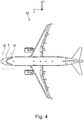
- Fig. 4 shows an aircraft 90 having a fuselage 8 as well as an arrangement 92, which may be comparable to the arrangements 2, 66 and 88 illustrated above.
Claims (11)
- Flugzeug (90), umfassend einen Rumpf, der einen Innenraum (6) begrenzt, umfassend einen vorderen Teil (2, 66, 88, 92), Folgendes umfassend:- ein Cockpit (4), das einen am weitesten vorn gelegenen Teil des Innenraums (6) belegt,- eine Cockpitwand (10), die das Cockpit (4) von einem restlichen Teil des Innenraums (6) trennt,- zumindest eine vordere Kabinentür (12), die direkt hinter der Cockpitwand (10) angeordnet ist, für den Zugang zum Innenraum (6) des Flugzeugs (90) von außerhalb des Rumpfes (8),- zumindest einen ersten modularen Installationsraum (22, 68) zum Aufnehmen von Installationsausrüstung,- mehrere Sitzreihen eines ersten Typs (30), jede gebildet durch erste Gruppen (26) einer vorbestimmten Anzahl von nebeneinander befindlichen Sitzen,- zumindest einen längs verlaufenden Gang (14), der sich entlang des Innenraums (6) durch die Sitzreihen des ersten Typs (30) erstreckt und dabei aneinander angrenzende Gruppen (26, 32, 86) von Sitzen (28) voneinander trennt, und- einen Zugangspfad (16, 80, 82) für jede der einen oder mehreren Kabinentüren (12), der sich von der jeweiligen Kabinentür (12) zu zumindest einem aus dem einen oder den mehreren längs verlaufenden Gängen (14) erstreckt, dabei einen Schnittbereich (18, 84) zwischen dem jeweiligen Zugangspfad (16, 80, 82) und dem jeweiligen längs verlaufenden Gang (14) schaffend,- zumindest einen zweiten modularen Installationsraum (42) zum Aufnehmen von Installationsausrüstung, wobei der zumindest eine zweite modulare Installationsraum (42) zwischen der Cockpitwand (10) und dem zumindest einen Zugangspfad (16, 80, 82) befindlich ist,
wobei sich der zumindest eine zweite modulare Installationsraum (42) bis zum Schnittbereich erstreckt,
wobei der zumindest eine erste modulare Installationsraum (22, 68) direkt vor den Sitzreihen des ersten Typs (30) angeordnet ist und sich in einer im Wesentlichen lateralen Richtung weniger als eine erste Gruppe (26) von Sitzen (28) erstreckt, die sich unmittelbar hinter dem zumindest einen ersten modularen Installationsraum (22, 68) befindet,
wobei zumindest einer aus dem einen oder den mehreren ersten modularen Installationsräumen (22, 68) zumindest eine zusätzliche erste Gruppe (26) von Sitzen (28) umfasst, und wobei sich der zumindest eine Zugangspfad (16, 80, 82) von dem zumindest einen längs verlaufenden Gang (14), in einem Winkel von mindestens 100° zu dem zumindest einen längs verlaufenden Gang (14), in eine Vorwärtsrichtung erstreckt. - Flugzeug (90) nach Anspruch 1,
wobei zumindest einer aus dem einen oder den mehreren ersten modularen Installationsräumen (22, 68) zumindest eine zweite Gruppe (32) von Sitzen (28) umfasst, die weniger Sitze (28) aufweist als eine erste Gruppe (26) von Sitzen direkt hinter dem ersten modularen Installationsraum (22, 68). - Flugzeug (90) nach einem der vorhergehenden Ansprüche,
wobei der zumindest eine erste modulare Installationsraum (26) ein Verstaumodul umfasst. - Flugzeug (90) nach einem der vorhergehenden Ansprüche,
wobei der zumindest eine erste modulare Installationsraum (22, 68) ein Monument umfasst, insbesondere eine Bordküche (70). - Flugzeug (90) nach Anspruch 4,
ferner umfassend zumindest einen klappbaren Sitz (76) der an einer nach vorn zeigenden Front (78) des Monuments angeordnet ist. - Flugzeug (90) nach Anspruch 4 oder 5,
wobei der Schnittbereich (18, 84) asymmetrisch vom Monument weg versetzt ist. - Flugzeug (90) nach einem der vorhergehenden Ansprüche,
wobei der zumindest eine zweite modulare Installationsraum (42) zumindest ein Toilettenmodul (44) umfasst. - Flugzeug (90) nach Anspruch 7,
wobei das zumindest eine Toilettenmodul (44) eine Toilettentür (54) umfasst, die zu dem zumindest einen längs verlaufenden Gang (14) zeigt. - Flugzeug (90) nach Anspruch 8,
wobei ein Flugbegleitersitz (56, 62) an der Toilettentür angeordnet ist. - Flugzeug (90) nach einem der vorhergehenden Ansprüche,
umfassend zwei vordere Kabinentüren (12) an zwei lateral gegenüberliegenden Seiten des Innenraums (6), sodass der zumindest eine längs verlaufende Gang (14) und die Zugangspfade (16, 80, 82) zu dem zumindest einen längs verlaufenden Gang (14) eine Y-Ganganordnung bilden. - Flugzeug (90) nach einem der vorhergehenden Ansprüche,
ferner umfassend zumindest einen Teilungsvorhang (64), der zwischen einer Position in oder an einem hinteren Ende des ersten Installationsraums (22, 68) zu einer Position vor dem zumindest einen ersten modularen Installationsraum (22, 68) zumindest teilweise entlang des längs verlaufenden Ganges (14) erweiterbar ist.
Priority Applications (3)
| Application Number | Priority Date | Filing Date | Title |
|---|---|---|---|
| EP17153365.6A EP3354568B1 (de) | 2017-01-26 | 2017-01-26 | Vordere innenraumanordnung für ein flugzeug |
| US15/878,019 US11358721B2 (en) | 2017-01-26 | 2018-01-23 | Forward interior space arrangement for an aircraft |
| CN201810077508.XA CN108382600B (zh) | 2017-01-26 | 2018-01-26 | 飞行器用的前内部空间布置 |
Applications Claiming Priority (1)
| Application Number | Priority Date | Filing Date | Title |
|---|---|---|---|
| EP17153365.6A EP3354568B1 (de) | 2017-01-26 | 2017-01-26 | Vordere innenraumanordnung für ein flugzeug |
Publications (2)
| Publication Number | Publication Date |
|---|---|
| EP3354568A1 EP3354568A1 (de) | 2018-08-01 |
| EP3354568B1 true EP3354568B1 (de) | 2020-07-08 |
Family
ID=57906570
Family Applications (1)
| Application Number | Title | Priority Date | Filing Date |
|---|---|---|---|
| EP17153365.6A Active EP3354568B1 (de) | 2017-01-26 | 2017-01-26 | Vordere innenraumanordnung für ein flugzeug |
Country Status (3)
| Country | Link |
|---|---|
| US (1) | US11358721B2 (de) |
| EP (1) | EP3354568B1 (de) |
| CN (1) | CN108382600B (de) |
Families Citing this family (3)
| Publication number | Priority date | Publication date | Assignee | Title |
|---|---|---|---|---|
| GB2577512B (en) * | 2018-09-26 | 2022-09-21 | Safran Seats Gb Ltd | Aircraft cabin |
| DE102018130231A1 (de) * | 2018-11-29 | 2020-06-04 | Airbus Operations Gmbh | Multifunktionale Sitzanordnung für eine Passagierkabine eines Fahrzeugs |
| DE102019002501B4 (de) * | 2019-04-05 | 2023-03-16 | Diehl Aviation Laupheim Gmbh | Kabinensegment mit Freiraum |
Family Cites Families (24)
| Publication number | Priority date | Publication date | Assignee | Title |
|---|---|---|---|---|
| NL8503017A (nl) * | 1985-11-04 | 1987-06-01 | Holman Associates | Nood- en/of markeerverlichting, in het bijzonder voor vlieg-, vaar- en voertuigen, van een dergelijke verlichting voorzien voor het tot stand brengen van een noodverlichting. |
| US6079669A (en) * | 1997-03-24 | 2000-06-27 | The Boeing Company | Dual pivot expandable lavatory |
| DE10148054A1 (de) * | 2001-09-28 | 2003-04-17 | Airbus Gmbh | Einrichtungen und Maßnahmen zur Verbesserung der Sicherheit im Luftverkehrsbetrieb |
| US6702231B2 (en) * | 2001-10-10 | 2004-03-09 | Gary Ward | Door system for creating and maintaining a secured area |
| US6474599B1 (en) * | 2001-12-11 | 2002-11-05 | Gerald D. Stomski | Aircraft security system |
| US20030189131A1 (en) * | 2002-04-05 | 2003-10-09 | Cloud Michael J. | Ballistic resistant flight deck door and method of making same |
| US7249737B2 (en) * | 2004-07-28 | 2007-07-31 | David Simmons | Cell door system for aircraft security |
| CA2576760C (en) * | 2004-08-03 | 2013-09-10 | Airbus | Door for closing an opening inside an aircraft |
| US20070102579A1 (en) * | 2005-09-13 | 2007-05-10 | Airbus Deutschland Gmbh | Modular structure |
| DE102005043610A1 (de) * | 2005-09-13 | 2007-03-22 | Airbus Deutschland Gmbh | Modulares Monument |
| DE102007003802B4 (de) * | 2007-01-25 | 2008-10-23 | Airbus Deutschland Gmbh | Flexible Kabelanbindung an Monumente innerhalb einer Flugzeugkabine |
| DE102007041391A1 (de) * | 2007-08-31 | 2009-03-05 | Airbus Deutschland Gmbh | Gesichertes Cockpit mit integriertem Aufenthaltsbereich und Sanitäranlagen |
| DE102010035375A1 (de) * | 2010-08-25 | 2012-03-01 | Airbus Operations Gmbh | Anordnung zum Aufnehmen von Passagieren in einem Verkehrsmittel |
| EP2627560B1 (de) * | 2010-10-15 | 2015-07-29 | Bombardier Inc. | Konfiguration eines flugzeuginnenraums |
| US9079668B2 (en) * | 2012-02-14 | 2015-07-14 | C&D Zodiac, Inc. | Integrated lavatory galley monument |
| DE102012003713A1 (de) | 2012-02-24 | 2013-08-29 | Airbus Operations Gmbh | Toilettenmodul für ein Fahrzeug und ein Fahrzeug mit einer Fahrzeugkabine und mindestens einem Toilettenmodul |
| DE102013008288A1 (de) * | 2013-05-15 | 2014-11-20 | Airbus Operations Gmbh | Flugzeugbereich |
| DE102013008291A1 (de) * | 2013-05-15 | 2014-11-20 | Airbus Operations Gmbh | Erweiterbares Flugzeugmonument |
| US9321533B2 (en) * | 2013-05-29 | 2016-04-26 | The Boeing Company | Aircraft passageway storage units |
| DE102014102378A1 (de) * | 2014-02-24 | 2015-08-27 | Airbus Operations Gmbh | Modul für eine Luftfahrzeugkabine mit einem an einer Tür angebrachten Sitz |
| DE102014104921A1 (de) * | 2014-04-07 | 2015-10-08 | Airbus Operations Gmbh | Haltesystem für eine bewegliche Komponente |
| DE102014110820A1 (de) * | 2014-07-30 | 2016-02-04 | Airbus Operations Gmbh | Sitzanordnung in einer Kabine eines Flugzeugs und Flugzeug mit einer Kabine und einer darin integrierten Sitzanordnung |
| US10583925B2 (en) * | 2015-02-12 | 2020-03-10 | The Boeing Company | Aft rest area assembly within an aircraft cabin |
| US9840332B2 (en) * | 2015-10-15 | 2017-12-12 | The Boeing Company | Deployable door-mounted seat |
-
2017
- 2017-01-26 EP EP17153365.6A patent/EP3354568B1/de active Active
-
2018
- 2018-01-23 US US15/878,019 patent/US11358721B2/en active Active
- 2018-01-26 CN CN201810077508.XA patent/CN108382600B/zh active Active
Non-Patent Citations (1)
| Title |
|---|
| None * |
Also Published As
| Publication number | Publication date |
|---|---|
| EP3354568A1 (de) | 2018-08-01 |
| CN108382600A (zh) | 2018-08-10 |
| CN108382600B (zh) | 2023-04-18 |
| US11358721B2 (en) | 2022-06-14 |
| US20180208316A1 (en) | 2018-07-26 |
Similar Documents
| Publication | Publication Date | Title |
|---|---|---|
| US9079668B2 (en) | Integrated lavatory galley monument | |
| EP3356229B1 (de) | Sitzanordnungen in einer flugzeugpassagiersuite mit gemeinsamem gangsuitenzugang | |
| US9550571B1 (en) | Overhead accommodations for aircraft | |
| US9045230B2 (en) | Lavatory Monument Assembly | |
| EP0901962B1 (de) | Rettungsvorrichtung für Ruhezone im oberen Bereich der Flugzeugkabine | |
| EP0901964B1 (de) | Ruhezone im oberen Bereich der Flugzeugkabine | |
| US10752364B2 (en) | Variable seat module with an ottoman for a seating arrangement in a vehicle cabin | |
| US20180273185A1 (en) | Aircraft cabin arrangement optimised for the installation of seats for the flight crew | |
| CN107949520B (zh) | 具有优化的乘客和机组人员服务区域的机舱布置 | |
| CN109789918B (zh) | 用于客机的舱室模块及布局 | |
| US11358721B2 (en) | Forward interior space arrangement for an aircraft | |
| US10124896B2 (en) | Galley module, cabin arrangement, and aircraft | |
| EP3608226B1 (de) | Toilettenanordnung für ein fahrzeug | |
| US20180208314A1 (en) | Space efficient cabin segment for a vehicle as well as a passenger cabin having a plurality of seats and such a cabin segment | |
| US10882619B2 (en) | Space optimized cabin arrangement for a vehicle as well as a passenger cabin having a plurality of seats and such a cabin arrangement | |
| CN112996722A (zh) | 飞机机舱 | |
| EP2803575B1 (de) | Flugzeugbereich | |
| US20220332425A1 (en) | Aircraft passenger seat unit and associated cabin arrangement | |
| US10894604B2 (en) | Arrangement in a cabin of an aircraft as well as an aircraft having such an arrangement |
Legal Events
| Date | Code | Title | Description |
|---|---|---|---|
| PUAI | Public reference made under article 153(3) epc to a published international application that has entered the european phase |
Free format text: ORIGINAL CODE: 0009012 |
|
| STAA | Information on the status of an ep patent application or granted ep patent |
Free format text: STATUS: THE APPLICATION HAS BEEN PUBLISHED |
|
| AK | Designated contracting states |
Kind code of ref document: A1 Designated state(s): AL AT BE BG CH CY CZ DE DK EE ES FI FR GB GR HR HU IE IS IT LI LT LU LV MC MK MT NL NO PL PT RO RS SE SI SK SM TR |
|
| AX | Request for extension of the european patent |
Extension state: BA ME |
|
| STAA | Information on the status of an ep patent application or granted ep patent |
Free format text: STATUS: REQUEST FOR EXAMINATION WAS MADE |
|
| 17P | Request for examination filed |
Effective date: 20190131 |
|
| RBV | Designated contracting states (corrected) |
Designated state(s): AL AT BE BG CH CY CZ DE DK EE ES FI FR GB GR HR HU IE IS IT LI LT LU LV MC MK MT NL NO PL PT RO RS SE SI SK SM TR |
|
| STAA | Information on the status of an ep patent application or granted ep patent |
Free format text: STATUS: EXAMINATION IS IN PROGRESS |
|
| 17Q | First examination report despatched |
Effective date: 20190702 |
|
| GRAP | Despatch of communication of intention to grant a patent |
Free format text: ORIGINAL CODE: EPIDOSNIGR1 |
|
| STAA | Information on the status of an ep patent application or granted ep patent |
Free format text: STATUS: GRANT OF PATENT IS INTENDED |
|
| INTG | Intention to grant announced |
Effective date: 20200129 |
|
| GRAS | Grant fee paid |
Free format text: ORIGINAL CODE: EPIDOSNIGR3 |
|
| GRAA | (expected) grant |
Free format text: ORIGINAL CODE: 0009210 |
|
| STAA | Information on the status of an ep patent application or granted ep patent |
Free format text: STATUS: THE PATENT HAS BEEN GRANTED |
|
| AK | Designated contracting states |
Kind code of ref document: B1 Designated state(s): AL AT BE BG CH CY CZ DE DK EE ES FI FR GB GR HR HU IE IS IT LI LT LU LV MC MK MT NL NO PL PT RO RS SE SI SK SM TR |
|
| REG | Reference to a national code |
Ref country code: AT Ref legal event code: REF Ref document number: 1288203 Country of ref document: AT Kind code of ref document: T Effective date: 20200715 Ref country code: CH Ref legal event code: EP |
|
| REG | Reference to a national code |
Ref country code: DE Ref legal event code: R096 Ref document number: 602017019201 Country of ref document: DE |
|
| REG | Reference to a national code |
Ref country code: IE Ref legal event code: FG4D |
|
| REG | Reference to a national code |
Ref country code: LT Ref legal event code: MG4D |
|
| REG | Reference to a national code |
Ref country code: AT Ref legal event code: MK05 Ref document number: 1288203 Country of ref document: AT Kind code of ref document: T Effective date: 20200708 |
|
| REG | Reference to a national code |
Ref country code: NL Ref legal event code: MP Effective date: 20200708 |
|
| PG25 | Lapsed in a contracting state [announced via postgrant information from national office to epo] |
Ref country code: LT Free format text: LAPSE BECAUSE OF FAILURE TO SUBMIT A TRANSLATION OF THE DESCRIPTION OR TO PAY THE FEE WITHIN THE PRESCRIBED TIME-LIMIT Effective date: 20200708 Ref country code: BG Free format text: LAPSE BECAUSE OF FAILURE TO SUBMIT A TRANSLATION OF THE DESCRIPTION OR TO PAY THE FEE WITHIN THE PRESCRIBED TIME-LIMIT Effective date: 20201008 Ref country code: PT Free format text: LAPSE BECAUSE OF FAILURE TO SUBMIT A TRANSLATION OF THE DESCRIPTION OR TO PAY THE FEE WITHIN THE PRESCRIBED TIME-LIMIT Effective date: 20201109 Ref country code: HR Free format text: LAPSE BECAUSE OF FAILURE TO SUBMIT A TRANSLATION OF THE DESCRIPTION OR TO PAY THE FEE WITHIN THE PRESCRIBED TIME-LIMIT Effective date: 20200708 Ref country code: AT Free format text: LAPSE BECAUSE OF FAILURE TO SUBMIT A TRANSLATION OF THE DESCRIPTION OR TO PAY THE FEE WITHIN THE PRESCRIBED TIME-LIMIT Effective date: 20200708 Ref country code: NO Free format text: LAPSE BECAUSE OF FAILURE TO SUBMIT A TRANSLATION OF THE DESCRIPTION OR TO PAY THE FEE WITHIN THE PRESCRIBED TIME-LIMIT Effective date: 20201008 Ref country code: GR Free format text: LAPSE BECAUSE OF FAILURE TO SUBMIT A TRANSLATION OF THE DESCRIPTION OR TO PAY THE FEE WITHIN THE PRESCRIBED TIME-LIMIT Effective date: 20201009 Ref country code: ES Free format text: LAPSE BECAUSE OF FAILURE TO SUBMIT A TRANSLATION OF THE DESCRIPTION OR TO PAY THE FEE WITHIN THE PRESCRIBED TIME-LIMIT Effective date: 20200708 Ref country code: FI Free format text: LAPSE BECAUSE OF FAILURE TO SUBMIT A TRANSLATION OF THE DESCRIPTION OR TO PAY THE FEE WITHIN THE PRESCRIBED TIME-LIMIT Effective date: 20200708 Ref country code: SE Free format text: LAPSE BECAUSE OF FAILURE TO SUBMIT A TRANSLATION OF THE DESCRIPTION OR TO PAY THE FEE WITHIN THE PRESCRIBED TIME-LIMIT Effective date: 20200708 |
|
| PG25 | Lapsed in a contracting state [announced via postgrant information from national office to epo] |
Ref country code: IS Free format text: LAPSE BECAUSE OF FAILURE TO SUBMIT A TRANSLATION OF THE DESCRIPTION OR TO PAY THE FEE WITHIN THE PRESCRIBED TIME-LIMIT Effective date: 20201108 Ref country code: RS Free format text: LAPSE BECAUSE OF FAILURE TO SUBMIT A TRANSLATION OF THE DESCRIPTION OR TO PAY THE FEE WITHIN THE PRESCRIBED TIME-LIMIT Effective date: 20200708 Ref country code: LV Free format text: LAPSE BECAUSE OF FAILURE TO SUBMIT A TRANSLATION OF THE DESCRIPTION OR TO PAY THE FEE WITHIN THE PRESCRIBED TIME-LIMIT Effective date: 20200708 Ref country code: PL Free format text: LAPSE BECAUSE OF FAILURE TO SUBMIT A TRANSLATION OF THE DESCRIPTION OR TO PAY THE FEE WITHIN THE PRESCRIBED TIME-LIMIT Effective date: 20200708 |
|
| PG25 | Lapsed in a contracting state [announced via postgrant information from national office to epo] |
Ref country code: NL Free format text: LAPSE BECAUSE OF FAILURE TO SUBMIT A TRANSLATION OF THE DESCRIPTION OR TO PAY THE FEE WITHIN THE PRESCRIBED TIME-LIMIT Effective date: 20200708 |
|
| REG | Reference to a national code |
Ref country code: DE Ref legal event code: R097 Ref document number: 602017019201 Country of ref document: DE |
|
| PG25 | Lapsed in a contracting state [announced via postgrant information from national office to epo] |
Ref country code: CZ Free format text: LAPSE BECAUSE OF FAILURE TO SUBMIT A TRANSLATION OF THE DESCRIPTION OR TO PAY THE FEE WITHIN THE PRESCRIBED TIME-LIMIT Effective date: 20200708 Ref country code: DK Free format text: LAPSE BECAUSE OF FAILURE TO SUBMIT A TRANSLATION OF THE DESCRIPTION OR TO PAY THE FEE WITHIN THE PRESCRIBED TIME-LIMIT Effective date: 20200708 Ref country code: RO Free format text: LAPSE BECAUSE OF FAILURE TO SUBMIT A TRANSLATION OF THE DESCRIPTION OR TO PAY THE FEE WITHIN THE PRESCRIBED TIME-LIMIT Effective date: 20200708 Ref country code: SM Free format text: LAPSE BECAUSE OF FAILURE TO SUBMIT A TRANSLATION OF THE DESCRIPTION OR TO PAY THE FEE WITHIN THE PRESCRIBED TIME-LIMIT Effective date: 20200708 Ref country code: IT Free format text: LAPSE BECAUSE OF FAILURE TO SUBMIT A TRANSLATION OF THE DESCRIPTION OR TO PAY THE FEE WITHIN THE PRESCRIBED TIME-LIMIT Effective date: 20200708 Ref country code: EE Free format text: LAPSE BECAUSE OF FAILURE TO SUBMIT A TRANSLATION OF THE DESCRIPTION OR TO PAY THE FEE WITHIN THE PRESCRIBED TIME-LIMIT Effective date: 20200708 |
|
| PLBE | No opposition filed within time limit |
Free format text: ORIGINAL CODE: 0009261 |
|
| STAA | Information on the status of an ep patent application or granted ep patent |
Free format text: STATUS: NO OPPOSITION FILED WITHIN TIME LIMIT |
|
| PG25 | Lapsed in a contracting state [announced via postgrant information from national office to epo] |
Ref country code: AL Free format text: LAPSE BECAUSE OF FAILURE TO SUBMIT A TRANSLATION OF THE DESCRIPTION OR TO PAY THE FEE WITHIN THE PRESCRIBED TIME-LIMIT Effective date: 20200708 |
|
| 26N | No opposition filed |
Effective date: 20210409 |
|
| PG25 | Lapsed in a contracting state [announced via postgrant information from national office to epo] |
Ref country code: SK Free format text: LAPSE BECAUSE OF FAILURE TO SUBMIT A TRANSLATION OF THE DESCRIPTION OR TO PAY THE FEE WITHIN THE PRESCRIBED TIME-LIMIT Effective date: 20200708 |
|
| PG25 | Lapsed in a contracting state [announced via postgrant information from national office to epo] |
Ref country code: SI Free format text: LAPSE BECAUSE OF FAILURE TO SUBMIT A TRANSLATION OF THE DESCRIPTION OR TO PAY THE FEE WITHIN THE PRESCRIBED TIME-LIMIT Effective date: 20200708 Ref country code: MC Free format text: LAPSE BECAUSE OF FAILURE TO SUBMIT A TRANSLATION OF THE DESCRIPTION OR TO PAY THE FEE WITHIN THE PRESCRIBED TIME-LIMIT Effective date: 20200708 |
|
| REG | Reference to a national code |
Ref country code: CH Ref legal event code: PL |
|
| GBPC | Gb: european patent ceased through non-payment of renewal fee |
Effective date: 20210126 |
|
| PG25 | Lapsed in a contracting state [announced via postgrant information from national office to epo] |
Ref country code: LU Free format text: LAPSE BECAUSE OF NON-PAYMENT OF DUE FEES Effective date: 20210126 |
|
| REG | Reference to a national code |
Ref country code: BE Ref legal event code: MM Effective date: 20210131 |
|
| PG25 | Lapsed in a contracting state [announced via postgrant information from national office to epo] |
Ref country code: CH Free format text: LAPSE BECAUSE OF NON-PAYMENT OF DUE FEES Effective date: 20210131 Ref country code: LI Free format text: LAPSE BECAUSE OF NON-PAYMENT OF DUE FEES Effective date: 20210131 Ref country code: GB Free format text: LAPSE BECAUSE OF NON-PAYMENT OF DUE FEES Effective date: 20210126 |
|
| PG25 | Lapsed in a contracting state [announced via postgrant information from national office to epo] |
Ref country code: IE Free format text: LAPSE BECAUSE OF NON-PAYMENT OF DUE FEES Effective date: 20210126 |
|
| PG25 | Lapsed in a contracting state [announced via postgrant information from national office to epo] |
Ref country code: IS Free format text: LAPSE BECAUSE OF FAILURE TO SUBMIT A TRANSLATION OF THE DESCRIPTION OR TO PAY THE FEE WITHIN THE PRESCRIBED TIME-LIMIT Effective date: 20201108 |
|
| PG25 | Lapsed in a contracting state [announced via postgrant information from national office to epo] |
Ref country code: BE Free format text: LAPSE BECAUSE OF NON-PAYMENT OF DUE FEES Effective date: 20210131 |
|
| PGFP | Annual fee paid to national office [announced via postgrant information from national office to epo] |
Ref country code: FR Payment date: 20230124 Year of fee payment: 7 |
|
| PGFP | Annual fee paid to national office [announced via postgrant information from national office to epo] |
Ref country code: DE Payment date: 20230123 Year of fee payment: 7 |
|
| PG25 | Lapsed in a contracting state [announced via postgrant information from national office to epo] |
Ref country code: CY Free format text: LAPSE BECAUSE OF FAILURE TO SUBMIT A TRANSLATION OF THE DESCRIPTION OR TO PAY THE FEE WITHIN THE PRESCRIBED TIME-LIMIT Effective date: 20200708 |
|
| PG25 | Lapsed in a contracting state [announced via postgrant information from national office to epo] |
Ref country code: HU Free format text: LAPSE BECAUSE OF FAILURE TO SUBMIT A TRANSLATION OF THE DESCRIPTION OR TO PAY THE FEE WITHIN THE PRESCRIBED TIME-LIMIT; INVALID AB INITIO Effective date: 20170126 |
|
| PG25 | Lapsed in a contracting state [announced via postgrant information from national office to epo] |
Ref country code: MK Free format text: LAPSE BECAUSE OF FAILURE TO SUBMIT A TRANSLATION OF THE DESCRIPTION OR TO PAY THE FEE WITHIN THE PRESCRIBED TIME-LIMIT Effective date: 20200708 |
|
| PGFP | Annual fee paid to national office [announced via postgrant information from national office to epo] |
Ref country code: DE Payment date: 20240119 Year of fee payment: 8 |