EP3354411B1 - Klappwerkbank für schreinerarbeiten - Google Patents
Klappwerkbank für schreinerarbeiten Download PDFInfo
- Publication number
- EP3354411B1 EP3354411B1 EP17290013.6A EP17290013A EP3354411B1 EP 3354411 B1 EP3354411 B1 EP 3354411B1 EP 17290013 A EP17290013 A EP 17290013A EP 3354411 B1 EP3354411 B1 EP 3354411B1
- Authority
- EP
- European Patent Office
- Prior art keywords
- work table
- vertical bar
- plate
- rear vertical
- table according
- Prior art date
- Legal status (The legal status is an assumption and is not a legal conclusion. Google has not performed a legal analysis and makes no representation as to the accuracy of the status listed.)
- Active
Links
Images


Classifications
-
- B—PERFORMING OPERATIONS; TRANSPORTING
- B25—HAND TOOLS; PORTABLE POWER-DRIVEN TOOLS; MANIPULATORS
- B25H—WORKSHOP EQUIPMENT, e.g. FOR MARKING-OUT WORK; STORAGE MEANS FOR WORKSHOPS
- B25H1/00—Work benches; Portable stands or supports for positioning portable tools or work to be operated on thereby
- B25H1/02—Work benches; Portable stands or supports for positioning portable tools or work to be operated on thereby of table type
- B25H1/04—Work benches; Portable stands or supports for positioning portable tools or work to be operated on thereby of table type portable
-
- A—HUMAN NECESSITIES
- A47—FURNITURE; DOMESTIC ARTICLES OR APPLIANCES; COFFEE MILLS; SPICE MILLS; SUCTION CLEANERS IN GENERAL
- A47B—TABLES; DESKS; OFFICE FURNITURE; CABINETS; DRAWERS; GENERAL DETAILS OF FURNITURE
- A47B3/00—Folding or stowable tables
- A47B3/08—Folding or stowable tables with legs pivoted to top or underframe
- A47B3/0803—Folding or stowable tables with legs pivoted to top or underframe the legs rotating around a vertical axis
- A47B2003/0806—Folding or stowable tables with legs pivoted to top or underframe the legs rotating around a vertical axis and the table top rotating around a horizontal axis
Definitions
- the invention relates to a workbench or carpentry table of the type comprising a work plate and support legs of said tray, the workbench being foldable or collapsible on itself for its transport or storage.
- Such workbenches or tables are known from the documents US 2013/0193283 A1 , US 2016/0058171 A1 , US 2003/0177960 A1 .
- Such folding workbenches are easily transportable and can be used on construction sites to maintain parts, for example of wood, arranged on the plate during the performance of operations such as cutting, sanding or other.
- This type of bench does not have sufficient stability to allow the realization of operations involving a transverse force to the feet. Indeed, such a force tends to fold the feet parallel to the plate. Thus, an additional mechanical member is generally necessary in order to block or stabilize the feet in the position of use of the workbench.
- the invention aims to overcome the aforementioned drawbacks and proposes a foldable bench different from the prior art, which can be easily transported and stored, and having good stability in the use position.
- the foldable bench comprises the features of claim 1.
- the workbench is able to be folded, and its stability in position of use is ensured.
- the tray is advantageously rectangular in shape, and comprises an upper face, a lower face, a rear edge, a front edge and two lateral edges.
- the at least one stabilizing means cooperating with the top of the plate is located above the plate, on its upper face, while the stabilizing means cooperating with the underside of the plate is located below the plate, on its underside. .
- the at least one stabilizing means cooperating with the underside of the plate consists of the arrangement of feet.
- the stability of the bench of the invention at the bottom of the plate is provided without additional mechanical member, which provides additional access and clearance useful for example in case of drilling, and generates manufacturing savings.
- each front vertical bar is able to be spread out of the bench and / or folded towards the inside of the bench.
- the workbench initially in position of use with the horizontal plate fixed to the front vertical bars, is adapted to be folded or folded from the inside, according to the operation described below with reference to FIGS.
- each rear vertical bar is positioned in contact with a distal end of the rear longitudinal edge of the plate, via the at least one means of rotation.
- Each rear vertical bar and therefore positioned outside the plate, in contact therewith.
- each rear vertical bar is fixed and each front vertical bar is movable.
- the rear vertical bars are advantageously interconnected by a rear horizontal bar.
- Each front vertical bar is positioned plumb with the front horizontal edge of the tray at each distal end of said front horizontal edge.
- each rear vertical bar comprises a first rotation means adapted to allow a rotational movement of the plate along the horizontal axis, and a second rotation means adapted to allow a rotational movement of the front vertical bar around said rear vertical bar, or along a vertical axis.
- the second rotation means adapted to allow a rotational movement of the front vertical bar around said rear vertical bar, is positioned in contact between the rear vertical bar and the at least one connecting means with the front vertical bar.
- the vertical front bar is connected to the rear vertical bar of each rigid element by two connecting means, one being preferably located in the upper part and the other in the lower part.
- each connecting means of the front vertical bar to the rear vertical bar of each rigid member is a horizontal horizontal bar.
- the fixing means with the plate preferably consists of a pin cooperating with a cavity or recess.
- each bar of the foot arrangement and each edge of the plate is of cylindrical shape, preferably of square section.
- the pin is advantageously located on the upper face of each vertical bar before, and the cavity or recess is advantageously located on the lower face of the front edge of the plate above said pin.
- the at least one rotation means advantageously consists of a hinge or a hinge or a pivot made using screws.
- the at least one stabilizing means cooperating with the top of the plate consists of at least one elastomeric plastic martyr, such as rubber, situated on the top of the plate, on its upper face, and extending transversely to the longitudinal direction of said tray.
- the plate comprises between two and eight rows of martyrs, and preferably five, arranged parallel to each other on the upper surface of the tray.
- a martyr is intended to support, protect and stabilize the piece to be cut, for example using a circular saw, sand, drill or other on the worktable.
- each martyr is removable so that it can be replaced if worn.
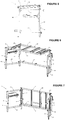
- the figure 1 illustrates an example of foldable bench according to the present invention.
- the folding workbench 1 is suitable for use on construction sites to support and maintain parts to be cut, sanded or otherwise.
- It is of parallelepipedal general shape and comprises a plate 2 resting on a foot arrangement comprising a first rigid element 3 and a second rigid element 4.
- the workbench 1 In the position of use, the workbench 1 is of length "I" equal to 130 cm, width L equal to 60 cm and height H equal to 80 cm.
- the plate 2 is in the form of a hollow rectangular frame having a longitudinal edge said before 2A, a longitudinal edge said rear 2B, and two lateral edges 2C and 2D.
- the rear vertical bars 3B and 4B are further interconnected by a rear horizontal bar 5, located in the lower position, close to the ground.
- each upper horizontal bar 3C, 4C connects respectively the vertical front bar 3A, 4A to the rear vertical bar 3B, 4B
- each lower horizontal bar 3D, 4D connects respectively the front vertical bar 3A, 4A to the rear vertical bar 3B, 4B , via two pivots, said second pivots 12B, each being located at the rear end of one of said horizontal bars.
- the rear vertical bars 3B and 4B are fixed while the front vertical bars 3A and 4A are movable. Their mobility will be described later.
- the plate 2 further comprises three transverse bars 20, 21 and 22 welded to the longitudinal edges before 2A and rear 2B of said plate.
- Each edge of the plate 2A, 2B, 2C, 2D, each vertical bar 3A, 4A, 3B, 4B, each horizontal bar 3C, 4C, 3D, 4D, 5 and each transverse bar 20, 21 and 22, are of square section of so as to allow the attachment of elements such as clamps.
- each transverse bar 20, 21, 22 comprises a metal rail 16 allowing the attachment of sliding stops 17 ( figure 10 ).
- Workbench 1 is essentially metallic.
- Martyrs 6 are removably attached to the distal lateral edges 2C and 2D of the plate 2, and on each transverse bar 20, 21 and 22. These martyrs will be described later with regard to the figure 4 .
- the plate 2 is hingedly pivotally mounted along a horizontal axis A-A, on each fixed rear vertical bar 3B and 4B of the workbench 1 with the first pivots 12A.
- the rear longitudinal edge 2B of the plate 2 is pivotally mounted pivotably along the axis A-A, corresponding to the longitudinal direction of said rear longitudinal edge 2B, on the vertical rear bars 3B and 4B of the workbench 1.
- the front longitudinal edge 2A of the plate is able to fit and dislocate vertical bars before 3A and 4A.
- the plate 2 is in a horizontal position in the position of use, and it is able to be arranged in a vertical position, as visible on the figure 2 , in the storage or transport position.
- Each front vertical bar 3A and 4A of each rigid element 3, 4 is pivotable through the pivoting of the upper horizontal bar respectively 3C, 4C, and the lower horizontal bar respectively 3D, 4D, along a vertical axis corresponding to the bar vertical rear respectively 3B and 4B ( figure 1 ). This pivoting is possible thanks to the presence of the second pivots 12B.
- the front vertical bars 3A and 4A are adapted to be folded towards the inside of the workbench 1, such as on the figure 2 .
- the tray 2 of the workbench is inserted in a frame delimited by its rear longitudinal edge 2B, the rear horizontal bar 5 and the vertical rear bars 3B and 4B of each rigid element 3, 4. It is in the same plane as said rear vertical bars and said rear horizontal bar. This allows the workbench to be compact when folded.
- the figure 8 represents in detail the pin 7 cooperating with the cavity 8.
- the cavity 8 is made by drilling a hole in the longitudinal front edge 2A of the plate, and by adding an elastomeric element 8A at the walls of said cavity, in order to absorb the games and hold the tray if it must be moved to the position of use.
- the cavity is elastomer.
- the martyr 6 has an inverted L-shaped elongate shape, so that it can be nested, in known manner, on one of the transverse bars 20, 21 or 22, or on one of the lateral edges 2C, 2D of the plate 2.
- the martyr 6 thus has a lower portion 6B of thickness "e” and an upper portion 6A of thickness E.
- the thickness "e” is less than the thickness E.
- the lower part 6A makes it possible to support the transverse forces.
- the thickness "e" of the lower portion 6B is about 0.9 cm while the thickness E of the upper portion 6A is about 1.3 cm.
- the upper part 6A of the martyr 6 is covered with an elastomer element 11.
- the elastomer element 11 essentially stabilizes the workpiece, so that said workpiece remains on the tray, without slipping, when a cutting movement is applied thereto.
- the plate 2 is raised a few centimeters (about 5 cm) thanks to the disengagement of the pin 7 of each recess 8 located on the underside of the longitudinal front edge 2A of the plate, above said pin, and thanks to the rotation of an angle ⁇ of 3 ° in the clockwise direction of the rear longitudinal edge 2B about the horizontal axis AA ( figure 1 ).
- the plate 2 is lowered in the vertical position, thanks to the rotation of an angle ⁇ of 3 ° in the counterclockwise direction of the rear longitudinal edge 2B about the horizontal axis AA ( figure 7 ).
- the front vertical bar 3A of the first rigid element 3 is folded inwards (to the left) by virtue of the rotation of an angle ⁇ of 120 ° ( figure 7 ) in the clockwise direction of each upper horizontal bar 3C and lower 3D of said first rigid member 3 about the vertical axis BB, and the front vertical bar 4A of the second rigid member 4 is folded inwards (to the right) through at the rotation of an angle ⁇ 'of 120 ° in the counterclockwise direction of each upper horizontal bar 4C and lower 4D of said second rigid member 4 around the rear vertical bar 4B of said second rigid member 4.
- the workbench 1 In the folded position ( figure 2 ), the workbench 1 is of length "l" and height H equal to its length "I” and its height H in the position of use, but it is of width L 'equal to 9 cm.
- the figure 9a shows a variant of the workbench 1 comprising an extension system 13.
- the extension system 13 is a Z-shaped elongate member having a lower horizontal leg 13A, a vertical leg 13B and an upper horizontal leg 13C.
- the vertical branch 13B connects the horizontal branches 13A and 13C.
- the extension system 13 further comprises a stop 14 adapted to block the workpiece or other on the extension system.
- the position and height of the support abutment 14 is adjustable so as to adapt to the size of the piece to be cut or otherwise.
- the extension system 13 is put in place on the workbench 1 ( Figure 9c ) by the diagonal insertion along the arrow F1, on the top of the plate 2, the lower horizontal leg 13A, between a lateral edge 2C or 2D of the plate 2 and the side bar respectively 20 or 22 nearest.
- extension system 13 is tilted along the arrow F2 in a horizontal position, so that the lower horizontal leg 13A is below the plane of the plate 2 ( figure 9a ).
- the vertical leg 13B then bears against the inner face of the lateral edge 2C or 2D, and the upper horizontal leg 13C bears against the upper face of said lateral edge ( figure 9a ).
- the upper horizontal leg 13C of the extension system 13 protrudes from the plate in the longitudinal direction of said plate so as to extend it.
- the figure 10 illustrates a variant according to which the workbench 1 comprises sliding stops 17.
- These stops 17 are adapted to be inserted on the rail 16 of each transverse bar 20, 21, 22, to slide along said rail, and to be blocked on said rail by means of a lock.
- the workbench according to the invention also makes it possible to use a miter saw.
- the saw (not shown) is advantageously arranged on at least one support such as a cross member of a length substantially equal to the width of the plate 2 and having rubber ends at its ends.
- the ends of the support are able to cooperate with the longitudinal edges before 2A and rear 2B of the plate and the saw is adapted to be fixed by any known means such as by screwing, on said support.
- the saw is fixed on two supports.
Landscapes
- Engineering & Computer Science (AREA)
- Mechanical Engineering (AREA)
- Workshop Equipment, Work Benches, Supports, Or Storage Means (AREA)
Claims (8)
- Klappwerkbank (1) mit einer Arbeitsplatte (2) auf einer Anordnung von Füßen (3, 4), mindestens ein Stabilisierungsmittel (3, 4) umfassend, das mit der Unterseite der Arbeitsplatte zusammenwirkt, sowie mindestens ein Stabilisierungsmittel (6), das mit der Oberseite der Arbeitsplatte zusammenwirkt, wobei sich jedes Stabilisierungsmittel (3, 4; 6) senkrecht zur Länge (l) der Arbeitsplatte (2) in ihrer ausgeklappten Arbeitsposition erstreckt, und beim Zuschneiden eines auf der Arbeitsplatte (2) angeordneten Werkstücks die Stabilität der Werkbank (1) gewährleistet,
dadurch gekennzeichnet, dass das mit der Oberseite der Arbeitsplatte zusammenwirkende Stabilisierungsmittel (6) aus mindestens einer Elastomerkunststoffschonerleiste wie zum Beispiel Gummi besteht, die abnehmbar auf der Oberseite der Arbeitsplatte fixiert ist und sich quer zur Längsrichtung dieser Arbeitsplatte erstreckt. - Werkbank nach Anspruch 1, dadurch gekennzeichnet, dass die Arbeitsplatte zwischen 2 und 8 Reihen von Schonerleisten umfasst, vorzugsweise 5, die parallel zueinander auf der Oberfläche der Arbeitsplatte angeordnet sind.
- Werkbank nach einem der vorausgehenden Ansprüche, dadurch gekennzeichnet, dass das mit der Unterseite der Arbeitsplatte (2) zusammenwirkende Stabilisierungsmittel (3, 4) aus der Anordnung von Füßen (3, 4) besteht.
- Werkbank nach einem der vorausgehenden Ansprüche, dadurch gekennzeichnet, dass die Anordnung von Füßen (3, 4) aus zwei starren Elementen (3, 4) besteht, die jeweils umfassen:- eine vordere senkrechte Stange (3A; 4A) mit mindestens einem abnehmbaren Befestigungsmittel an der Arbeitsplatte, und- eine hintere senkrechte Stange (3B; 4B) mit mindestens einem Drehmittel (12A, 12B), das zum einen eine Drehbewegung der Arbeitsplatte (2) um eine waagrechte Achse (A-A) ermöglicht, und zum anderen eine Drehbewegung der vorderen senkrechten Stange (3A ;4A) um die hintere senkrechte Stange (3B; 4B),wobei die vorderen (3A; 4A) und hinteren (3B; 4B) senkrechten Stangen jedes starren Elements (3; 4) durch mindestens ein Verbindungsmittel (3C, 3D; 4C, 4D) miteinander verbunden sind.
- Werkbank nach Anspruch 4, dadurch gekennzeichnet, dass das Befestigungsmittel aus einem Zapfen (7) besteht, der mit einer Vertiefung (8) oder Aussparung zusammenwirkt.
- Werkbank nach einem der Ansprüche 4 bis 5, dadurch gekennzeichnet, dass jede hintere senkrechte Stange (3B ;4B) ein erstes Drehmittel (12A) umfasst, das eine Drehbewegung der Arbeitsplatte (2) um die waagrechte Achse (A-A) zulässt, sowie ein zweites Drehmittel (12B), das eine Drehbewegung der vorderen senkrechten Stange (3A; 4A) um die hintere senkrechte Stange (3B; 4B) ermöglicht.
- Werkbank nach einem der Ansprüche 4 bis 6, dadurch gekennzeichnet, dass die hinteren senkrechten Stangen (3B, 4B) fest sind.
- Werkbank nach einem der Ansprüche 4 bis 7, dadurch gekennzeichnet, dass sich die Arbeitsplatte (2) zwischen den hinteren senkrechten Stangen (3B, 4B) jedes starren Elements (3; 4) der Anordnung von Füßen senkrecht einfügen lässt.
Priority Applications (3)
| Application Number | Priority Date | Filing Date | Title |
|---|---|---|---|
| PT172900136T PT3354411T (pt) | 2017-01-27 | 2017-01-27 | Bancada de trabalho rebatível |
| EP17290013.6A EP3354411B1 (de) | 2017-01-27 | 2017-01-27 | Klappwerkbank für schreinerarbeiten |
| ES17290013T ES2760576T3 (es) | 2017-01-27 | 2017-01-27 | Mesa de trabajo de carpintería abatible |
Applications Claiming Priority (1)
| Application Number | Priority Date | Filing Date | Title |
|---|---|---|---|
| EP17290013.6A EP3354411B1 (de) | 2017-01-27 | 2017-01-27 | Klappwerkbank für schreinerarbeiten |
Publications (2)
| Publication Number | Publication Date |
|---|---|
| EP3354411A1 EP3354411A1 (de) | 2018-08-01 |
| EP3354411B1 true EP3354411B1 (de) | 2019-09-04 |
Family
ID=58094342
Family Applications (1)
| Application Number | Title | Priority Date | Filing Date |
|---|---|---|---|
| EP17290013.6A Active EP3354411B1 (de) | 2017-01-27 | 2017-01-27 | Klappwerkbank für schreinerarbeiten |
Country Status (3)
| Country | Link |
|---|---|
| EP (1) | EP3354411B1 (de) |
| ES (1) | ES2760576T3 (de) |
| PT (1) | PT3354411T (de) |
Family Cites Families (4)
| Publication number | Priority date | Publication date | Assignee | Title |
|---|---|---|---|---|
| US6752090B2 (en) * | 2002-03-22 | 2004-06-22 | Innovative Storage Designs, Inc. | Folding desk |
| US6997115B2 (en) * | 2003-09-19 | 2006-02-14 | Lockwood Joshua C | Steady table |
| US8727327B2 (en) * | 2009-08-14 | 2014-05-20 | Mark T. Miller | Work table having elevated support members |
| US9381605B2 (en) * | 2013-09-05 | 2016-07-05 | Hmc Holdings, Llc | Collapsible workstation |
-
2017
- 2017-01-27 ES ES17290013T patent/ES2760576T3/es active Active
- 2017-01-27 PT PT172900136T patent/PT3354411T/pt unknown
- 2017-01-27 EP EP17290013.6A patent/EP3354411B1/de active Active
Non-Patent Citations (1)
| Title |
|---|
| None * |
Also Published As
| Publication number | Publication date |
|---|---|
| PT3354411T (pt) | 2019-10-30 |
| ES2760576T3 (es) | 2020-05-14 |
| EP3354411A1 (de) | 2018-08-01 |
Similar Documents
| Publication | Publication Date | Title |
|---|---|---|
| CA2815322C (fr) | Planche a repasser comportant deux pieds disposes selon une configuration en x | |
| FR3032775A1 (fr) | Support mural rabattable | |
| EP3354411B1 (de) | Klappwerkbank für schreinerarbeiten | |
| WO2007107669A2 (fr) | Treteau repliable | |
| EP1696771B1 (de) | Vorrichtung zur anzeige einer reihe von objekten | |
| EP1097656B1 (de) | Tischart welche mit mindestens einem faltbaren Fuss oder Untergestell versehen ist | |
| BE1004648A6 (fr) | Chariot porteur pour portes et fenetres coulissantes. | |
| FR2717445A1 (fr) | Dispositif de calage de bouteilles de gaz en vue de leur transport, notamment dans le coffre d'un véhicule automobile. | |
| FR3107463A1 (fr) | Table de découpe pour chantier de construction | |
| FR2985533A1 (fr) | Dispositif de guidage et de levage de garde-corps de plateforme de travail en encorbellement | |
| FR2523829A1 (fr) | Ensemble transformable pouvant etre utilise a volonte comme table, etabli ou echafaudage | |
| FR2945523A1 (fr) | Dispositif pour le transport d'objets, notamment d'elements prefabriques sous forme de plaques. | |
| EP1693276B1 (de) | Zusammenklappbarer Kinderwagen mit einer drehbaren Fussstütze | |
| EP1574276B1 (de) | Sägetisch für Platten oder ähnliches | |
| FR2630312A1 (fr) | Dispositif de pied rabattable destine a etre fixe a un plateau, et table equipee de ce dispositif | |
| FR3148049A1 (fr) | Structure pliable de travail en encorbellement pour le réglage manuel de la longueur d’extension d’un châssis latéral | |
| FR2794392A1 (fr) | Etabli pliant perfectionne | |
| EP0025737B1 (de) | Transportierbare Werkzeugmaschine | |
| FR2873316A1 (fr) | Servante d'atelier | |
| WO2003092438A2 (fr) | Tabourets extensibles | |
| FR2474289A1 (fr) | Perfectionnements aux tables a pietement repliable | |
| FR3088690A1 (fr) | Systeme de verrouillage d’un deplacement entre un profile creux et une paroi | |
| FR3165879A1 (fr) | Table élévatrice pour la réparation et/ou la maintenance et/ou le contrôle d’engin roulant | |
| FR2897854A1 (fr) | Dispositif et ensemble d'emmagasinage d'au moins une serie de receptacles parallelepipediques | |
| FR2750836A1 (fr) | Table pliante |
Legal Events
| Date | Code | Title | Description |
|---|---|---|---|
| STAA | Information on the status of an ep patent application or granted ep patent |
Free format text: STATUS: UNKNOWN |
|
| PUAI | Public reference made under article 153(3) epc to a published international application that has entered the european phase |
Free format text: ORIGINAL CODE: 0009012 |
|
| STAA | Information on the status of an ep patent application or granted ep patent |
Free format text: STATUS: REQUEST FOR EXAMINATION WAS MADE |
|
| 17P | Request for examination filed |
Effective date: 20170413 |
|
| AK | Designated contracting states |
Kind code of ref document: A1 Designated state(s): AL AT BE BG CH CY CZ DE DK EE ES FI FR GB GR HR HU IE IS IT LI LT LU LV MC MK MT NL NO PL PT RO RS SE SI SK SM TR |
|
| AX | Request for extension of the european patent |
Extension state: BA ME |
|
| GRAP | Despatch of communication of intention to grant a patent |
Free format text: ORIGINAL CODE: EPIDOSNIGR1 |
|
| STAA | Information on the status of an ep patent application or granted ep patent |
Free format text: STATUS: GRANT OF PATENT IS INTENDED |
|
| RIC1 | Information provided on ipc code assigned before grant |
Ipc: B25H 1/04 20060101AFI20190507BHEP Ipc: A47B 3/08 20060101ALI20190507BHEP |
|
| INTG | Intention to grant announced |
Effective date: 20190529 |
|
| GRAS | Grant fee paid |
Free format text: ORIGINAL CODE: EPIDOSNIGR3 |
|
| GRAA | (expected) grant |
Free format text: ORIGINAL CODE: 0009210 |
|
| STAA | Information on the status of an ep patent application or granted ep patent |
Free format text: STATUS: THE PATENT HAS BEEN GRANTED |
|
| AK | Designated contracting states |
Kind code of ref document: B1 Designated state(s): AL AT BE BG CH CY CZ DE DK EE ES FI FR GB GR HR HU IE IS IT LI LT LU LV MC MK MT NL NO PL PT RO RS SE SI SK SM TR |
|
| REG | Reference to a national code |
Ref country code: GB Ref legal event code: FG4D Free format text: NOT ENGLISH |
|
| REG | Reference to a national code |
Ref country code: CH Ref legal event code: EP |
|
| REG | Reference to a national code |
Ref country code: AT Ref legal event code: REF Ref document number: 1174716 Country of ref document: AT Kind code of ref document: T Effective date: 20190915 |
|
| REG | Reference to a national code |
Ref country code: CH Ref legal event code: NV Representative=s name: KIRKER AND CIE S.A., CH |
|
| REG | Reference to a national code |
Ref country code: DE Ref legal event code: R096 Ref document number: 602017006768 Country of ref document: DE Ref country code: IE Ref legal event code: FG4D Free format text: LANGUAGE OF EP DOCUMENT: FRENCH |
|
| REG | Reference to a national code |
Ref country code: PT Ref legal event code: SC4A Ref document number: 3354411 Country of ref document: PT Date of ref document: 20191030 Kind code of ref document: T Free format text: AVAILABILITY OF NATIONAL TRANSLATION Effective date: 20191018 |
|
| REG | Reference to a national code |
Ref country code: NL Ref legal event code: FP |
|
| REG | Reference to a national code |
Ref country code: LT Ref legal event code: MG4D |
|
| PG25 | Lapsed in a contracting state [announced via postgrant information from national office to epo] |
Ref country code: FI Free format text: LAPSE BECAUSE OF FAILURE TO SUBMIT A TRANSLATION OF THE DESCRIPTION OR TO PAY THE FEE WITHIN THE PRESCRIBED TIME-LIMIT Effective date: 20190904 Ref country code: NO Free format text: LAPSE BECAUSE OF FAILURE TO SUBMIT A TRANSLATION OF THE DESCRIPTION OR TO PAY THE FEE WITHIN THE PRESCRIBED TIME-LIMIT Effective date: 20191204 Ref country code: SE Free format text: LAPSE BECAUSE OF FAILURE TO SUBMIT A TRANSLATION OF THE DESCRIPTION OR TO PAY THE FEE WITHIN THE PRESCRIBED TIME-LIMIT Effective date: 20190904 Ref country code: BG Free format text: LAPSE BECAUSE OF FAILURE TO SUBMIT A TRANSLATION OF THE DESCRIPTION OR TO PAY THE FEE WITHIN THE PRESCRIBED TIME-LIMIT Effective date: 20191204 Ref country code: HR Free format text: LAPSE BECAUSE OF FAILURE TO SUBMIT A TRANSLATION OF THE DESCRIPTION OR TO PAY THE FEE WITHIN THE PRESCRIBED TIME-LIMIT Effective date: 20190904 Ref country code: LT Free format text: LAPSE BECAUSE OF FAILURE TO SUBMIT A TRANSLATION OF THE DESCRIPTION OR TO PAY THE FEE WITHIN THE PRESCRIBED TIME-LIMIT Effective date: 20190904 |
|
| PG25 | Lapsed in a contracting state [announced via postgrant information from national office to epo] |
Ref country code: AL Free format text: LAPSE BECAUSE OF FAILURE TO SUBMIT A TRANSLATION OF THE DESCRIPTION OR TO PAY THE FEE WITHIN THE PRESCRIBED TIME-LIMIT Effective date: 20190904 Ref country code: LV Free format text: LAPSE BECAUSE OF FAILURE TO SUBMIT A TRANSLATION OF THE DESCRIPTION OR TO PAY THE FEE WITHIN THE PRESCRIBED TIME-LIMIT Effective date: 20190904 Ref country code: GR Free format text: LAPSE BECAUSE OF FAILURE TO SUBMIT A TRANSLATION OF THE DESCRIPTION OR TO PAY THE FEE WITHIN THE PRESCRIBED TIME-LIMIT Effective date: 20191205 Ref country code: RS Free format text: LAPSE BECAUSE OF FAILURE TO SUBMIT A TRANSLATION OF THE DESCRIPTION OR TO PAY THE FEE WITHIN THE PRESCRIBED TIME-LIMIT Effective date: 20190904 |
|
| PG25 | Lapsed in a contracting state [announced via postgrant information from national office to epo] |
Ref country code: PL Free format text: LAPSE BECAUSE OF FAILURE TO SUBMIT A TRANSLATION OF THE DESCRIPTION OR TO PAY THE FEE WITHIN THE PRESCRIBED TIME-LIMIT Effective date: 20190904 Ref country code: RO Free format text: LAPSE BECAUSE OF FAILURE TO SUBMIT A TRANSLATION OF THE DESCRIPTION OR TO PAY THE FEE WITHIN THE PRESCRIBED TIME-LIMIT Effective date: 20190904 Ref country code: EE Free format text: LAPSE BECAUSE OF FAILURE TO SUBMIT A TRANSLATION OF THE DESCRIPTION OR TO PAY THE FEE WITHIN THE PRESCRIBED TIME-LIMIT Effective date: 20190904 |
|
| REG | Reference to a national code |
Ref country code: ES Ref legal event code: FG2A Ref document number: 2760576 Country of ref document: ES Kind code of ref document: T3 Effective date: 20200514 |
|
| PG25 | Lapsed in a contracting state [announced via postgrant information from national office to epo] |
Ref country code: SM Free format text: LAPSE BECAUSE OF FAILURE TO SUBMIT A TRANSLATION OF THE DESCRIPTION OR TO PAY THE FEE WITHIN THE PRESCRIBED TIME-LIMIT Effective date: 20190904 Ref country code: CZ Free format text: LAPSE BECAUSE OF FAILURE TO SUBMIT A TRANSLATION OF THE DESCRIPTION OR TO PAY THE FEE WITHIN THE PRESCRIBED TIME-LIMIT Effective date: 20190904 Ref country code: IS Free format text: LAPSE BECAUSE OF FAILURE TO SUBMIT A TRANSLATION OF THE DESCRIPTION OR TO PAY THE FEE WITHIN THE PRESCRIBED TIME-LIMIT Effective date: 20200224 Ref country code: SK Free format text: LAPSE BECAUSE OF FAILURE TO SUBMIT A TRANSLATION OF THE DESCRIPTION OR TO PAY THE FEE WITHIN THE PRESCRIBED TIME-LIMIT Effective date: 20190904 |
|
| REG | Reference to a national code |
Ref country code: DE Ref legal event code: R097 Ref document number: 602017006768 Country of ref document: DE |
|
| PLBE | No opposition filed within time limit |
Free format text: ORIGINAL CODE: 0009261 |
|
| STAA | Information on the status of an ep patent application or granted ep patent |
Free format text: STATUS: NO OPPOSITION FILED WITHIN TIME LIMIT |
|
| REG | Reference to a national code |
Ref country code: AT Ref legal event code: UEP Ref document number: 1174716 Country of ref document: AT Kind code of ref document: T Effective date: 20190904 |
|
| PG2D | Information on lapse in contracting state deleted |
Ref country code: IS |
|
| PG25 | Lapsed in a contracting state [announced via postgrant information from national office to epo] |
Ref country code: DK Free format text: LAPSE BECAUSE OF FAILURE TO SUBMIT A TRANSLATION OF THE DESCRIPTION OR TO PAY THE FEE WITHIN THE PRESCRIBED TIME-LIMIT Effective date: 20190904 Ref country code: IS Free format text: LAPSE BECAUSE OF FAILURE TO SUBMIT A TRANSLATION OF THE DESCRIPTION OR TO PAY THE FEE WITHIN THE PRESCRIBED TIME-LIMIT Effective date: 20200105 |
|
| 26N | No opposition filed |
Effective date: 20200605 |
|
| PG25 | Lapsed in a contracting state [announced via postgrant information from national office to epo] |
Ref country code: MC Free format text: LAPSE BECAUSE OF FAILURE TO SUBMIT A TRANSLATION OF THE DESCRIPTION OR TO PAY THE FEE WITHIN THE PRESCRIBED TIME-LIMIT Effective date: 20190904 Ref country code: SI Free format text: LAPSE BECAUSE OF FAILURE TO SUBMIT A TRANSLATION OF THE DESCRIPTION OR TO PAY THE FEE WITHIN THE PRESCRIBED TIME-LIMIT Effective date: 20190904 |
|
| PG25 | Lapsed in a contracting state [announced via postgrant information from national office to epo] |
Ref country code: IE Free format text: LAPSE BECAUSE OF NON-PAYMENT OF DUE FEES Effective date: 20200127 |
|
| PG25 | Lapsed in a contracting state [announced via postgrant information from national office to epo] |
Ref country code: TR Free format text: LAPSE BECAUSE OF FAILURE TO SUBMIT A TRANSLATION OF THE DESCRIPTION OR TO PAY THE FEE WITHIN THE PRESCRIBED TIME-LIMIT Effective date: 20190904 Ref country code: MT Free format text: LAPSE BECAUSE OF FAILURE TO SUBMIT A TRANSLATION OF THE DESCRIPTION OR TO PAY THE FEE WITHIN THE PRESCRIBED TIME-LIMIT Effective date: 20190904 Ref country code: CY Free format text: LAPSE BECAUSE OF FAILURE TO SUBMIT A TRANSLATION OF THE DESCRIPTION OR TO PAY THE FEE WITHIN THE PRESCRIBED TIME-LIMIT Effective date: 20190904 |
|
| PG25 | Lapsed in a contracting state [announced via postgrant information from national office to epo] |
Ref country code: MK Free format text: LAPSE BECAUSE OF FAILURE TO SUBMIT A TRANSLATION OF THE DESCRIPTION OR TO PAY THE FEE WITHIN THE PRESCRIBED TIME-LIMIT Effective date: 20190904 |
|
| PGFP | Annual fee paid to national office [announced via postgrant information from national office to epo] |
Ref country code: DE Payment date: 20241218 Year of fee payment: 9 |
|
| PGFP | Annual fee paid to national office [announced via postgrant information from national office to epo] |
Ref country code: ES Payment date: 20250203 Year of fee payment: 9 |
|
| PGFP | Annual fee paid to national office [announced via postgrant information from national office to epo] |
Ref country code: CH Payment date: 20250201 Year of fee payment: 9 Ref country code: AT Payment date: 20250120 Year of fee payment: 9 |
|
| PGFP | Annual fee paid to national office [announced via postgrant information from national office to epo] |
Ref country code: IT Payment date: 20250113 Year of fee payment: 9 |
|
| PGFP | Annual fee paid to national office [announced via postgrant information from national office to epo] |
Ref country code: PT Payment date: 20251020 Year of fee payment: 10 |
|
| PGFP | Annual fee paid to national office [announced via postgrant information from national office to epo] |
Ref country code: GB Payment date: 20251204 Year of fee payment: 10 |
|
| PGFP | Annual fee paid to national office [announced via postgrant information from national office to epo] |
Ref country code: NL Payment date: 20251217 Year of fee payment: 10 Ref country code: FR Payment date: 20251014 Year of fee payment: 10 |
|
| PGFP | Annual fee paid to national office [announced via postgrant information from national office to epo] |
Ref country code: BE Payment date: 20251217 Year of fee payment: 10 |
|
| REG | Reference to a national code |
Ref country code: CH Ref legal event code: U11 Free format text: ST27 STATUS EVENT CODE: U-0-0-U10-U11 (AS PROVIDED BY THE NATIONAL OFFICE) Effective date: 20260201 |
|
| PGFP | Annual fee paid to national office [announced via postgrant information from national office to epo] |
Ref country code: LU Payment date: 20260122 Year of fee payment: 10 |