EP3354345B1 - Grinding screen for a device for grinding bulk material - Google Patents
Grinding screen for a device for grinding bulk material Download PDFInfo
- Publication number
- EP3354345B1 EP3354345B1 EP18162594.8A EP18162594A EP3354345B1 EP 3354345 B1 EP3354345 B1 EP 3354345B1 EP 18162594 A EP18162594 A EP 18162594A EP 3354345 B1 EP3354345 B1 EP 3354345B1
- Authority
- EP
- European Patent Office
- Prior art keywords
- sieve
- housing part
- comminuting
- shredding
- housing
- Prior art date
- Legal status (The legal status is an assumption and is not a legal conclusion. Google has not performed a legal analysis and makes no representation as to the accuracy of the status listed.)
- Active
Links
- 238000000227 grinding Methods 0.000 title description 9
- 239000013590 bulk material Substances 0.000 title 1
- 238000012423 maintenance Methods 0.000 claims description 21
- 238000006073 displacement reaction Methods 0.000 claims description 8
- 230000008439 repair process Effects 0.000 description 6
- 238000004140 cleaning Methods 0.000 description 3
- 238000005520 cutting process Methods 0.000 description 3
- 238000004519 manufacturing process Methods 0.000 description 2
- 239000002699 waste material Substances 0.000 description 2
- 239000002023 wood Substances 0.000 description 2
- 239000002028 Biomass Substances 0.000 description 1
- 239000011093 chipboard Substances 0.000 description 1
- 235000013325 dietary fiber Nutrition 0.000 description 1
- 238000009826 distribution Methods 0.000 description 1
- 230000000694 effects Effects 0.000 description 1
- 235000013305 food Nutrition 0.000 description 1
- 230000005484 gravity Effects 0.000 description 1
- 239000000463 material Substances 0.000 description 1
- 238000003801 milling Methods 0.000 description 1
- 239000008188 pellet Substances 0.000 description 1
- 238000007873 sieving Methods 0.000 description 1
- 125000006850 spacer group Chemical group 0.000 description 1
Images


Classifications
-
- B—PERFORMING OPERATIONS; TRANSPORTING
- B02—CRUSHING, PULVERISING, OR DISINTEGRATING; PREPARATORY TREATMENT OF GRAIN FOR MILLING
- B02C—CRUSHING, PULVERISING, OR DISINTEGRATING IN GENERAL; MILLING GRAIN
- B02C13/00—Disintegrating by mills having rotary beater elements ; Hammer mills
- B02C13/26—Details
- B02C13/282—Shape or inner surface of mill-housings
- B02C13/284—Built-in screens
-
- B—PERFORMING OPERATIONS; TRANSPORTING
- B02—CRUSHING, PULVERISING, OR DISINTEGRATING; PREPARATORY TREATMENT OF GRAIN FOR MILLING
- B02C—CRUSHING, PULVERISING, OR DISINTEGRATING IN GENERAL; MILLING GRAIN
- B02C13/00—Disintegrating by mills having rotary beater elements ; Hammer mills
- B02C13/13—Disintegrating by mills having rotary beater elements ; Hammer mills with horizontal rotor shaft and combined with sifting devices, e.g. for making powdered fuel
-
- B—PERFORMING OPERATIONS; TRANSPORTING
- B02—CRUSHING, PULVERISING, OR DISINTEGRATING; PREPARATORY TREATMENT OF GRAIN FOR MILLING
- B02C—CRUSHING, PULVERISING, OR DISINTEGRATING IN GENERAL; MILLING GRAIN
- B02C13/00—Disintegrating by mills having rotary beater elements ; Hammer mills
- B02C13/26—Details
- B02C13/282—Shape or inner surface of mill-housings
-
- B—PERFORMING OPERATIONS; TRANSPORTING
- B27—WORKING OR PRESERVING WOOD OR SIMILAR MATERIAL; NAILING OR STAPLING MACHINES IN GENERAL
- B27L—REMOVING BARK OR VESTIGES OF BRANCHES; SPLITTING WOOD; MANUFACTURE OF VENEER, WOODEN STICKS, WOOD SHAVINGS, WOOD FIBRES OR WOOD POWDER
- B27L11/00—Manufacture of wood shavings, chips, powder, or the like; Tools therefor
Definitions
- the invention relates to a shredding sieve according to the preamble of claim 1 for a device for shredding piece goods, which has a housing with at least a first housing part and a second housing part and a rotor on which tools for shredding the piece goods are attached.
- the shredded piece goods can get out of an effective area of the rotor via the shredding sieve.
- Such a crushing sieve is, for example, from DE 472 243 C known.
- This document describes a beater or hammer mill whose grinding path can be moved out of the housing through a door. In order to avoid contact between the grinding track and the rotor, part of the grinding track can be lowered by actuating a screw spindle.
- Devices for shredding piece goods are used in a variety of ways. In many branches of industry, for example in the chipboard industry, in the production of pellets and briquettes or in the production of biomass, it is necessary to shred piece goods, in particular wood.
- the material to be crushed can, for. B. consist of waste wood, planing, milling or sawdust, coarse classifier or green waste.
- So-called hammer mills or hammer crushers are usually used for this purpose. These mostly have a drum-shaped housing in which a rotor is arranged, over the outer surface of which tools for comminuting the piece goods are distributed. These tools can be breaking tools, for example hammers, or cutting tools, for example knives.
- the rotor is in operation of the Device set in rotation so that the tools come into contact with the piece goods to be shredded. This piece of cargo is shredded by the tools.
- the comminuted piece goods usually leave the area of action of the rotor through the comminuting sieve, which can also be a perforated disk or the like, for example.
- the piece goods then move through a discharge shaft in order to be transported away afterwards.
- the area of action of the rotor is defined as the spatial area in which the shredding tools move.
- the effective area is therefore generally cylindrical and has a radius that corresponds to the sum of the rotor radius and the tool length. In this area the tools unfold their effect and can shred the piece goods to be shredded.
- a shredding sieve is understood to mean any device by means of which it can be achieved that components of the shredded piece goods whose size exceeds a maximum size are held inside the housing, while components of the shredded piece goods whose size is below the maximum size can leave the device .
- Both the crushing tools and the crushing sieves are subject to constant wear. As a result, they have to be replaced or serviced regularly. In addition, it is possible that the crushing sieve used should be exchanged for another one, since, for example, the crushed piece goods should have a different size distribution.
- the JP 2011 251216 A is provided for this purpose with a two-part sieve which is arranged below the rotor and which is arched and screwed to the housing via a portafilter. If the screw connection is loosened, the two portafilter fold apart and pivot down into the housing. They can be pushed out together via doors provided in the housing.
- the DE 40 08 276 A1 discloses a hammer mill with a radially adjustable sieve shell for comminuting grains, long or pre-chopped roughage and other agricultural and food products, in which the sieve shell forming the grinding chamber encloses the rotor and consists of two halves which are individually rotatably mounted in radially adjustable sieve holders .
- the lower sieve holder which consists of an assembly, moves in the direction of the center of the rotor, the halves of the sieve are inevitably moved in the direction of the impact circle of the beaters.
- the DE 19713264 C1 describes a hammer mill with two rotors rotating in opposite directions and multi-part breaking tracks that can be pulled out from the side.
- Part of the grinding track is designed to be pivotable and can be brought into a working position by being pushed into the housing.
- the CA 2429244 describes a comminuting device which has a housing part which can be displaced linearly together with a part of the comminuting sieve so that the rotor is accessible.
- the invention has for its object to provide a crushing sieve according to the To improve the preamble of claim 1 so that maintenance and repair of the device or replacement of the shredding sieve or parts of the device is possible simply, quickly and safely for those involved.
- the invention solves the problem posed by a comminuting sieve according to claim 1.
- the comminuting sieve has a pivoting part which is mounted pivotably about a pivot axis and which can be pivoted into a holding position in that the first housing part and the sliding part of the comminuting sieve are brought into the maintenance position, the pivoting part forms a walk-on work platform in the holding position.
- the device for comminuting piece goods has a discharge shaft for comminuted piece goods and the pivoting portion of the shredding sieve spans the discharge shaft at least partially in the holding position. With this configuration, the rotor can be exposed in a single operation and access to both the rotor and the tools can be achieved.
- the shredding sieve is accessible so that cleaning, maintenance, repair or replacement work can be carried out easily.
- the shredding sieve can remain in the assembled state, which significantly reduces the time required and the workload.
- part of the rotor for example part of its outer surface, is made accessible.
- the rotor is rotatably mounted so that the entire surface area is accessible by turning the rotor. Accessible means that the necessary cleaning, maintenance or repairs are possible.
- the first housing part can be displaced relative to the second housing part, for example, via a hydraulic system or a spindle drive.
- a hydraulic system or a spindle drive Of course, other types of drive are also conceivable.
- the comminuting sieve has a pivoting part which is mounted pivotably about a pivot axis and which can pivot into a holding position is in that the first housing part and the sliding part of the shredding sieve are brought into the maintenance position, the pivoting part in the holding position forming a work platform that can be walked on.
- the housing and the rotor are mostly drum-shaped or cylindrical.
- This cylinder usually has an extension running in the axial direction that is too large to be able to carry out maintenance and repair work over the entire cylinder surface of the respective rotor or of the shredding sieve by simply reaching into it. It is therefore imperative for a person who is to carry out the corresponding work to climb into the device.
- no separate work platform is provided in these devices, since the distance between the tools located on the rotor and the comminuting sieve should be kept as small as possible when the device is in operation. There is no structural space for a separate work platform, which enables comfortable work during maintenance or cleaning work.
- the design described here ensures that part of the comminuting sieve, namely the pivoting part, forms a work platform and thus enables particularly convenient and safe work inside the device.
- the sliding part and the pivoting part of the comminuting sieve are releasably connected to one another by at least one locking bolt.
- This connection is particularly advantageously achieved by two locking bolts.
- a pivotable connection between the sliding part and the pivoting part of the comminuting sieve is achieved in a particularly simple manner and, in addition, this connection is easy to detach. If, for example, a used crushing sieve is to be exchanged for another comminuting sieve that has, for example, a different mesh size, the The swivel part of the respective shredding sieve can be easily removed by loosening the locking bolts and exchanged for the swiveling part of the other shredding sieve.
- the device advantageously has a discharge chute for shredded piece goods, the pivoting portion of the shredding sieve in the holding position at least partially spanning this discharge chute.
- the piece goods to be comminuted are introduced into the device from above.
- the shredded piece goods leave the device mostly downwards following the force of gravity.
- the discharge chute is consequently arranged at this point, through which the shredded piece goods fall and are then transported away, for example, with a chain conveyor, a conveyor belt, a double screw conveyor or other conveyors.
- a connecting shaft, the so-called discharge shaft is therefore installed at the outlet of the device, which can be a hammer mill, for example.
- the pivoting part is pivoted into the holding position when the first housing part is brought from the working position into the maintenance position.
- the pivoting part not only forms the work platform that can be walked on, but advantageously also covers at least part of this discharge shaft and thus also increases work safety.
- the pivoting portion of the shredding sieve makes up approximately one third of the total shredding sieve. This makes it possible, advantageously, to span the discharge shaft completely.
- a portafilter is arranged on the first housing part and a counter-screen carrier is arranged on the second housing part in such a way that the comminuting sieve between the portafilter and the Counter-sieve carrier can be clamped in that the first housing part is brought from the maintenance position into the working position.
- the pivoting part of the comminuting sieve which is particularly detachably fastened, is designed in the form of a grinding track, for example a comminuting grinding track or a rasping track.
- a grinding track for example a comminuting grinding track or a rasping track.
- the swivel portion of the shredding sieve is out of the holding position pivotable into a sieve position by bringing the first housing part out of the maintenance position into the working position. Since the pivoting part forms the accessible work platform in the holding position, it is consequently not necessary to bring the pivoting part into the sieve position, for example by hand or by actuating an actuator, in which the pivoting part of the shredding sieve acts as a comminuting sieve part. Rather, this is already achieved in that the first housing part is brought from the maintenance position into the working position. It is consequently impossible, for example, after maintenance or repair work has been completed, to forget to bring the pivoting part from the holding position into the sieving position before the first housing part is brought from the maintenance position into the working position. Such a separate work step is not necessary.
- a projection is arranged on the pivot part 2, which slides along a guide arranged on the second housing part and thus ensures pivoting of the pivot part when the first housing part is displaced relative to the second housing part.
- the projection can also be designed, for example, as a roller or wheel that rolls on the guide. In this way, both when moving the two housing parts apart from the working position to the maintenance position and in the opposite direction, it is ensured that a smooth and flowing movement of the swivel part is achieved and wedging, falling or tilting of the swivel part can be almost reliably ruled out. If the pivoting part of one comminuting sieve is replaced by the pivoting part of another comminuting sieve, only the projection has to be placed on the guide provided for it. No further adjustment or alignment of the components relative to one another is necessary.
- the comminuting sieve preferably has a partially cylindrical shape with a sieve radius, and the portafilter and the counter-sieve holder are designed to accommodate different comminuting sieves which have sieve radii different from one another.
- the sieve supports are screwed in, whereby different sieve radii can be realized by, for example, different spacer inserts in the device and the corresponding sieve supports can be changed very quickly. This is necessary, for example, in order to adapt the sieve spacings from the striking or cutting tool, which is arranged on the respective rotor, to the comminuting sieve, if, for example, another, for example shorter or longer, tool is arranged on the rotor.
- adjustable sieve hold-downs which can be part of the portafilter and the counter-sieve carrier, for example, are adjusted to a new dimension. Then another comminuting sieve with a, for example, larger or smaller sieve radius can be inserted and used.
- the crushing sieve is again clamped in that, after the crushing sieve has been inserted into the portafilter, the two machine bodies are moved towards each other, for example by hydraulics or mechanics, so that the first housing part is moved from the maintenance position to the working position. In this way alone, the shredding sieve is clamped between the portafilter and the counter-sieve carrier and secured in the machine.
- the portafilter and the counter-screen carrier are therefore preferably designed to be adaptable to different screen radii.
- the comminuting sieve is preferably attached to the portafilter by at least one quick-release bolt. This achieves an even more secure attachment of the shredding sieve to the portafilter, so that the shredding sieve on the portafilter is prevented from slipping on the portafilter, especially when the two housing parts move together while the first housing part is being moved from the maintenance position to the working position.
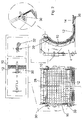
- Figure 1 shows in the upper area a side view of a device 2 according to a first embodiment of the present invention.
- the device 2 has a first housing part 4 and a second housing part 8, which are shown enlarged in the lower area.
- a rotor 6 is located between the two housing parts 4, 8.
- the first housing part 4 is shown enlarged.
- a portafilter 10 on which a displacement part 12 of a comminuting sieve, shown to the right, is arranged.
- the displacement part 12 has a partially cylindrical contour and, in particular, has a sieve radius on the inside.
- a door 24 is shown, which is arranged on the first housing part 4 via hinges 22 and can be opened using a handle 26. In this way, access is possible, for example, to a rear side of the sliding part 12 of the comminuting sieve.
- Figure 1 also shows a pivoting part 14, which via locking bolts 16 is attached to the sliding part 12.
- the locking bolts 16 are guided through receptacles 18 on the pivot part 14 and through receptacles 20 on the displacement part 12 and thus connect the two components 12, 14 to one another.
- the sliding part 12 and the pivoting part 14 together form the shredding sieve.
- the pivot portion 14 is shown in two different positions.
- the pivoting part 14 is shown in the holding position in somewhat thicker lines, in which a surface 34 can be walked on and serves as a work platform.
- the pivoting component 14 is shown in the sieve position in somewhat thinner lines and pivoted about the receptacles 18.
- a projection 36 is shown, which in the assembled state slides along a guide 38 when the first housing part 4 and thus also the shredding sieve attached to it is brought from the working to the maintenance position or vice versa.
- the pivot portion 14 is pivoted about the pivot axis which is formed by the receptacles 18, 20 and the locking bolts 16. If the first housing part 4 is in the working position, the projection 36 engages in an undercut 40 provided for this purpose.
- Figure 2 shows an enlarged representation of some of the components already mentioned.
- the pivoting part 14 also has a sieve radius, but does not continue the sieve radius of the displacement part 12 in the position shown.
- the pivoting part 14 is consequently in the holding position.
- FIG. 1 To the left of this is a front view of the shredding sieve, the individual holes 28 of the sieve being shown.
- the shredding sieve and in particular the one in the lower left area of the Figure 2 shown The sliding part 12 of the shredding sieve is fastened to the portafilter 10 via quick-release bolts 30.
- This is in the upper left area of the Figure 2 shown enlarged.
- the quick release bolts 30 can be seen, which are shown in the upper left area once in the non-connected and once in the connected state.
- the quick release bolt 30 connects the sliding part 12 of the shredding sieve to the portafilter 10.
- a safety clip 32 is provided to prevent the bolt from being pulled out.
- Also in the upper right area of the Figure 2 a quick release bolt 30 is shown.
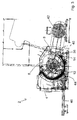
- Figure 3 shows the device 2 in the closed state.
- a drive device 42 by means of which the rotor 6 can be set in rotation.
- the first housing part 4 and the second housing part 8 are in direct contact with one another, so that the first housing part 4 is in the working position.
- Both the sliding part 12 and the pivoting part 14, which together form the shredding sieve, are shown as dark elements.
- the projection 36 On the right-hand part of the pivoting part 14, the projection 36, which has engaged in the undercut 40, can be seen.
- a hydraulic piston 44 is shown below the rotor 6, which in FIG Figure 3 shown condition has its minimum length.
- the first housing part 4 can be displaced relative to the second housing part 8 via a rail system 46 as soon as the hydraulic piston 44 moves the two components 4, 8 away from one another.
- the displacement part 12 is between the portafilter 10 and the, for example, in Figure 1 shown Gegenensieblic 48 clamped.
- Figure 4 shows the device 2 from Figure 3 when open. It can be seen that the first housing part 4 has been displaced along the rail system 46 relative to the second housing part 8 and the rotor 6. The pivoting part 14 of the shredding sieve is now in the holding position and can be used as a work platform. The protrusion 36 is along has slid off the guide 38 and has ensured that the pivoting part 14 is pivoted relative to the sliding part 12.
Description
Die Erfindung betrifft ein Zerkleinerungssieb gemäß dem Oberbegriff des Patentanspruchs 1, für eine Vorrichtung zum Zerkleinern von Stückgut, die ein Gehäuse mit wenigstens einem ersten Gehäuseteil und einem zweiten Gehäuseteil und einen Rotor, an dem Werkzeuge zum Zerkleinern des Stückguts angebracht sind, aufweist. Über das Zerkleinerungssieb kann das zerkleinerte Stückgut aus einem Wirkungsbereich des Rotors gelangen.The invention relates to a shredding sieve according to the preamble of claim 1 for a device for shredding piece goods, which has a housing with at least a first housing part and a second housing part and a rotor on which tools for shredding the piece goods are attached. The shredded piece goods can get out of an effective area of the rotor via the shredding sieve.
Ein solches Zerkleinerungssieb ist beispielsweise aus der
Üblicherweise verlässt das zerkleinerte Stückgut den Wirkungsbereich des Rotors durch das Zerkleinerungssieb, das beispielsweise auch eine Lochscheibe oder ähnliches sein kann. Das Stückgut bewegt sich dann durch einen Austragsschacht um anschließend abtransportiert zu werden.The comminuted piece goods usually leave the area of action of the rotor through the comminuting sieve, which can also be a perforated disk or the like, for example. The piece goods then move through a discharge shaft in order to be transported away afterwards.
Der Wirkungsbereich des Rotors ist dabei als der Raumbereich definiert, in dem sich die Zerkleinerungswerkzeuge bewegen. Der Wirkungsbereich ist also im Regelfall zylindrisch und weist einen Radius auf, der der Summe aus Rotorradius und Werkzeuglänge entspricht. In diesem Bereich entfalten die Werkzeuge ihre Wirkung und können das zu zerkleinernde Stückgut zerkleinern.The area of action of the rotor is defined as the spatial area in which the shredding tools move. The effective area is therefore generally cylindrical and has a radius that corresponds to the sum of the rotor radius and the tool length. In this area the tools unfold their effect and can shred the piece goods to be shredded.
Unter einem Zerkleinerungssieb wird vorliegend jede Vorrichtung verstanden, durch die erreicht werden kann, dass Bestandteile des zerkleinerten Stückgutes, deren Größe eine Maximalgröße überschreiten, im Innern des Gehäuses gehalten werden, während Bestandteile des zerkleinerten Stückgutes, deren Größe die Maximalgröße unterschreitet, die Vorrichtung verlassen können.In the present case, a shredding sieve is understood to mean any device by means of which it can be achieved that components of the shredded piece goods whose size exceeds a maximum size are held inside the housing, while components of the shredded piece goods whose size is below the maximum size can leave the device .
Sowohl die Zerkleinerungswerkzeuge als auch die Zerkleinerungssiebe sind ständigem Verschleiß unterworfen. Sie müssen folglich regelmäßig ausgetauscht oder gewartet werden. Zudem ist es möglich, dass das verwendete Zerkleinerungssieb gegen ein anderes ausgetauscht werden soll, da beispielsweise das zerkleinerte Stückgut eine andere Größenverteilung aufweisen soll.Both the crushing tools and the crushing sieves are subject to constant wear. As a result, they have to be replaced or serviced regularly. In addition, it is possible that the crushing sieve used should be exchanged for another one, since, for example, the crushed piece goods should have a different size distribution.
Aus dem Stand der Technik ist es bekannt, an einer Seite einer Hammermühle eine oder mehrere Türen oder vergleichbare Öffnungen vorzusehen, durch die ein Zugang zu der Mantelfläche des Rotors und zu den an dem Rotor angebrachten Zerkleinerungswerkzeugen erreicht wird. Durch diese Öffnung können Wartungs- und Reparaturarbeiten durchgeführt werden. Dabei muss jedoch nach dem Öffnen der Türen auch das Zerkleinerungssieb entfernt werden, um Zugang zu dem Rotor und den daran befindlichen Werkzeugen zu erhalten. Dies ist in der Regel aufwendig und zeitintensiv, da das Zerkleinerungssieb oftmals mit einer Vielzahl von Schrauben mit dem Gehäuse der Hammermühle verbunden ist.It is known from the prior art to provide one or more doors or comparable openings on one side of a hammer mill, through which access to the outer surface of the rotor and to the comminuting tools attached to the rotor is achieved. Maintenance and repair work can be carried out through this opening. However, it must After opening the doors, the shredding screen can also be removed to gain access to the rotor and the tools attached to it. This is usually complex and time-consuming, since the comminuting sieve is often connected to the housing of the hammer mill with a large number of screws.
Die
Die
Die
Die
Der Erfindung liegt die Aufgabe zugrunde, ein Zerkleinerungssieb gemäß dem Oberbegriff des Anspruchs 1 so zu verbessern, dass eine Wartung und Reparatur der Vorrichtung oder ein Austausch des Zerkleinerungssiebes oder von Teilen der Vorrichtung einfach, schnell und für die Beteiligten sicher möglich ist.The invention has for its object to provide a crushing sieve according to the To improve the preamble of claim 1 so that maintenance and repair of the device or replacement of the shredding sieve or parts of the device is possible simply, quickly and safely for those involved.
Die Erfindung löst die gestellte Aufgabe durch ein Zerkleinerungssieb gemäß Anspruch 1. Das Zerkleinerungssieb weist einen um eine Schwenkachse schwenkbar gelagerten Schwenkanteil auf, der in eine Halteposition schwenkbar ist, indem der erste Gehäuseteil und der Verschiebeanteil des Zerkleinerungssiebs in die Wartungsposition gebracht werden, wobei der Schwenkanteil in der Halteposition eine begehbare Arbeitsplattform bildet. Die Vorrichtung zum Zerkleinern von Stückgut weist ein Austragsschacht für zerkleinertes Stückgut auf und der Schwenkanteil des Zerkleinerungssiebs überspannt in der Halteposition den Austragsschacht zumindest teilweise. Durch diese Ausgestaltung kann mit einem einzigen Arbeitsgang der Rotor freigelegt und so ein Zugang sowohl zum Rotor als auch zu den Werkzeugen erreicht werden. Zudem wird auch das Zerkleinerungssieb zugänglich, so dass Reinigungs-, Wartungs-, Reparatur- oder Austauscharbeiten einfach durchgeführt werden können. Dabei kann das Zerkleinerungssieb im montierten Zustand verbleiben, wodurch der zeitliche Aufwand und der Arbeitsauwand deutlich reduziert werden. Natürlich ist es ausreichend, wenn ein Teil des Rotors, beispielsweise ein Teil seiner Mantelfläche, zugänglich gemacht wird. Der Rotor ist drehbar gelagert, so dass durch Drehen des Rotors die gesamte Mantelfläche zugänglich ist. Zugänglich bedeutet dabei, dass die nötigen Reinigungs- oder Wartungsarbeiten oder Reparaturen möglich sind.The invention solves the problem posed by a comminuting sieve according to claim 1. The comminuting sieve has a pivoting part which is mounted pivotably about a pivot axis and which can be pivoted into a holding position in that the first housing part and the sliding part of the comminuting sieve are brought into the maintenance position, the pivoting part forms a walk-on work platform in the holding position. The device for comminuting piece goods has a discharge shaft for comminuted piece goods and the pivoting portion of the shredding sieve spans the discharge shaft at least partially in the holding position. With this configuration, the rotor can be exposed in a single operation and access to both the rotor and the tools can be achieved. In addition, the shredding sieve is accessible so that cleaning, maintenance, repair or replacement work can be carried out easily. The shredding sieve can remain in the assembled state, which significantly reduces the time required and the workload. Of course, it is sufficient if part of the rotor, for example part of its outer surface, is made accessible. The rotor is rotatably mounted so that the entire surface area is accessible by turning the rotor. Accessible means that the necessary cleaning, maintenance or repairs are possible.
Das Verschieben des ersten Gehäuseteils relativ zu dem zweiten Gehäuseteil kann beispielsweise über eine Hydraulik oder einen Spindelantrieb erfolgen. Natürlich sind auch andere Antriebsarten denkbar.The first housing part can be displaced relative to the second housing part, for example, via a hydraulic system or a spindle drive. Of course, other types of drive are also conceivable.
Das Zerkleinerungssieb weist einen um eine Schwenkachse schwenkbar gelagerten Schwenkanteil auf, der in eine Halteposition schwenkbar ist, indem der erste Gehäuseteil und der Verschiebeanteil des Zerkleinerungssiebs in die Wartungsposition gebracht werden, wobei der Schwenkanteil in der Halteposition eine begehbare Arbeitsplattform bildet.The comminuting sieve has a pivoting part which is mounted pivotably about a pivot axis and which can pivot into a holding position is in that the first housing part and the sliding part of the shredding sieve are brought into the maintenance position, the pivoting part in the holding position forming a work platform that can be walked on.
Wie bereits dargelegt, ist bei derartigen Vorrichtungen das Gehäuse und der Rotor zumeist trommel- oder zylinderförmig. Dieser Zylinder weist dabei zumeist eine in axialer Richtung verlaufende Ausdehnung auf, die zu groß ist, als dass man durch einfaches Hineingreifen, beispielsweise Wartungs- und Reparaturarbeiten über die gesamte Zylindermantelfläche des jeweiligen Rotors oder des Zerkleinerungssiebs ausführen könnte. Daher ist es zwingend notwendig für eine Person, die die entsprechenden Arbeiten ausführen soll, in die Vorrichtung hineinzusteigen. Dabei ist jedoch in diesen Vorrichtungen in der Regel keine separate Arbeitsplattform vorgesehen, da im Betrieb der Vorrichtung der Abstand zwischen den Werkzeugen, die sich am Rotor befinden, und dem Zerkleinerungssieb so klein wie möglich gehalten werden soll. Für eine separate Arbeitsplattform, die ein bequemes Arbeiten bei Wartungs- oder Reinigungsarbeiten ermöglicht, fehlt der bauliche Raum.As already stated, in such devices the housing and the rotor are mostly drum-shaped or cylindrical. This cylinder usually has an extension running in the axial direction that is too large to be able to carry out maintenance and repair work over the entire cylinder surface of the respective rotor or of the shredding sieve by simply reaching into it. It is therefore imperative for a person who is to carry out the corresponding work to climb into the device. In this case, however, as a rule, no separate work platform is provided in these devices, since the distance between the tools located on the rotor and the comminuting sieve should be kept as small as possible when the device is in operation. There is no structural space for a separate work platform, which enables comfortable work during maintenance or cleaning work.
Durch die hier beschriebene Ausgestaltung wird jedoch erreicht, dass ein Teil des Zerkleinerungssiebes, nämlich der Schwenkanteil, eine Arbeitsplattform bildet und so eine besonders bequeme und sichere Arbeit auch im Innern der Vorrichtung ermöglicht.However, the design described here ensures that part of the comminuting sieve, namely the pivoting part, forms a work platform and thus enables particularly convenient and safe work inside the device.
Vorteilhafterweise sind der Verschiebeanteil und der Schwenkanteil des Zerkleinerungssiebs durch wenigstens einen Verriegelungsbolzen lösbar miteinander verbunden. Besonders vorteilhafterweise wird diese Verbindung durch zwei Verriegelungsbolzen erreicht. Auf diese Weise wird besonders einfach eine schwenkbare Verbindung zwischen dem Verschiebeanteil und dem Schwenkanteil des Zerkleinerungssiebs erreicht und zudem eine leichte Lösbarkeit dieser Verbindung gewährleistet. Soll beispielsweise ein verwendetes Zerkleinerungssieb gegen ein anderes Zerkleinerungssieb ausgetauscht werden, das beispielsweise über eine veränderte Maschengröße verfügt, kann der Schwenkanteil des jeweiligen Zerkleinerungssiebs einfach durch Lösen der Verriegelungsbolzen entfernt und gegen den Schwenkanteil des anderen Zerkleinerungssiebs ausgetauscht werden.Advantageously, the sliding part and the pivoting part of the comminuting sieve are releasably connected to one another by at least one locking bolt. This connection is particularly advantageously achieved by two locking bolts. In this way, a pivotable connection between the sliding part and the pivoting part of the comminuting sieve is achieved in a particularly simple manner and, in addition, this connection is easy to detach. If, for example, a used crushing sieve is to be exchanged for another comminuting sieve that has, for example, a different mesh size, the The swivel part of the respective shredding sieve can be easily removed by loosening the locking bolts and exchanged for the swiveling part of the other shredding sieve.
Vorteilhafterweise verfügt die Vorrichtung über einen Austragsschacht für zerkleinertes Stückgut, wobei der Schwenkanteil des Zerkleinerungssiebs in der Halteposition diesen Austragsschacht zumindest teilweise überspannt. Herkömmlicherweise wird das zu zerkleinernde Stückgut von oben in die Vorrichtung eingeführt. Das zerkleinerte Stückgut verlässt die Vorrichtung der Schwerkraft folgend zumeist nach unten. An dieser Stelle ist folglich der Austragsschacht angeordnet, durch den das zerkleinerte Stückgut hindurch fällt und anschließend beispielsweise mit einem Kettenförderer, einem Förderband, einer Doppelförderschnecke oder anderen Förderern abtransportiert wird. Daher ist ein Verbindungsschacht, der sogenannte Austragsschacht, am Ausgang der Vorrichtung, die beispielsweise eine Hammermühle sein kann, installiert.The device advantageously has a discharge chute for shredded piece goods, the pivoting portion of the shredding sieve in the holding position at least partially spanning this discharge chute. Conventionally, the piece goods to be comminuted are introduced into the device from above. The shredded piece goods leave the device mostly downwards following the force of gravity. The discharge chute is consequently arranged at this point, through which the shredded piece goods fall and are then transported away, for example, with a chain conveyor, a conveyor belt, a double screw conveyor or other conveyors. A connecting shaft, the so-called discharge shaft, is therefore installed at the outlet of the device, which can be a hammer mill, for example.
Beim aufgefahrenen oder geöffneten Maschinengehäuse, also in dem Zustand, in dem sich der erste Gehäuseteil in der Wartungsposition befindet und somit zumindest ein Teil des Rotors zugänglich ist, besteht die Gefahr, dass Personen, die im Inneren der Vorrichtung arbeiten, durch den Austragsschacht fallen und sich so Verletzungen zuziehen. Vorliegend wird jedoch der Schwenkanteil in die Halteposition verschwenkt, wenn der erste Gehäuseteil aus der Arbeitsposition in die Wartungsposition gebracht wird. Dabei bildet der Schwenkanteil nicht nur die begehbare Arbeitsplattform, sondern überdeckt vorteilhafterweise auch zumindest einen Teil dieses Austragsschachtes und erhöht somit zudem die Arbeitssicherheit. Vorteilhafterweise bildet der Schwenkanteil des Zerkleinerungssiebes etwa ein Drittel des gesamten Zerkleinerungssiebs. Damit ist es möglich, den Austragsschacht vorteilzugsweise ganz zu überspannen.When the machine housing is raised or opened, i.e. in the state in which the first housing part is in the maintenance position and thus at least part of the rotor is accessible, there is a risk that people who work inside the device will fall through the discharge shaft and get injured in this way. In the present case, however, the pivoting part is pivoted into the holding position when the first housing part is brought from the working position into the maintenance position. The pivoting part not only forms the work platform that can be walked on, but advantageously also covers at least part of this discharge shaft and thus also increases work safety. Advantageously, the pivoting portion of the shredding sieve makes up approximately one third of the total shredding sieve. This makes it possible, advantageously, to span the discharge shaft completely.
Als vorteilhaft hat sich herausgestellt, wenn an dem ersten Gehäuseteil ein Siebträger und an dem zweiten Gehäuseteil ein Gegensiebträger derart angeordnet sind, dass das Zerkleinerungssieb zwischen dem Siebträger und dem Gegensiebträger einklemmbar ist, indem das erste Gehäuseteil aus der Wartungsposition in die Arbeitsposition gebracht wird. Durch das Zusammenfahren des ersten Gehäuseteils und des zweiten Gehäuseteils relativ zueinander aufeinander zu wird folglich erreicht, dass das Zerkleinerungssieb zwischen dem Siebträger und dem Gegensiebträger, die an den unterschiedlichen Gehäuseteilen angeordnet sind, eingeklemmt wird. Eine komplizierte und zeitaufwändige Befestigung des Zerkleinerungssiebs am jeweiligen Siebträger, beispielsweise über eine Vielzahl von Schrauben oder ähnliche Verbindungselemente, entfällt daher. Der Austausch eines Zerkleinerungssiebs gegen ein anderes Zerkleinerungssieb wird auf diese Weise schnell und einfach möglich.It has been found to be advantageous if a portafilter is arranged on the first housing part and a counter-screen carrier is arranged on the second housing part in such a way that the comminuting sieve between the portafilter and the Counter-sieve carrier can be clamped in that the first housing part is brought from the maintenance position into the working position. By moving the first housing part and the second housing part together relative to one another it is consequently achieved that the comminuting sieve is clamped between the sieve holder and the counter-sieve holder, which are arranged on the different housing parts. Complicated and time-consuming fastening of the comminuting sieve to the respective portafilter, for example by means of a large number of screws or similar connecting elements, is therefore not necessary. In this way, it is quick and easy to exchange a shredding sieve for another shredding sieve.
Da auf diese Weise die Anzahl der verlierbaren Elemente, beispielsweise Schrauben oder Bolzen, stark reduziert wird, wird auch die Gefahr von unzureichend befestigten Zerkleinerungssieben reduziert. Es besteht in dieser Ausge-staltung keine Möglichkeit mehr, das Zerkleinerungssieb unzureichend, beispielsweise mit nicht ausreichend vielen Schrauben, am jeweiligen Siebträger zu befestigen. Sobald das erste Gehäuseteil und das zweite Gehäuseteil aufeinander zu gefahren werden und sich das erste Gehäuseteil in der Arbeitsposition befindet, ist gleichzeitig sichergestellt, dass sich das Zerkleinerungssieb ordnungsgemäß befestigt an der gewünschten und vorgesehen Position befindet. Auch dadurch wird die Arbeitssicherheit erhöht und das Unfallrisiko stark reduziert.Since the number of elements that can be lost, for example screws or bolts, is greatly reduced in this way, the risk of inadequately fastened comminuting sieves is also reduced. In this embodiment, there is no longer any possibility of insufficiently fastening the comminuting sieve, for example with an insufficient number of screws, on the respective portafilter. As soon as the first housing part and the second housing part are moved towards each other and the first housing part is in the working position, it is ensured at the same time that the comminuting sieve is properly secured in the desired and intended position. This also increases work safety and greatly reduces the risk of accidents.
In einer vorteilhaften Ausgestaltung ist der insbesondere lösbar befestigte Schwenkanteil des Zerkleinerungssiebs in Form einer Mahlbahn, beispielsweise einer Zerkleinerungsmahlbahn oder einer Raspelbahn ausgebildet. Durch die einfache Lösbarkeit des Schwenkanteils am Verschiebeanteil des Zerkleinerungssiebes ist hier eine besonders leichte Austauschbarkeit gegeben, so dass den jeweiligen Anforderungen an das zu zerkleinernde Stückgut schnell und einfach Rechnung getragen werden kann.In an advantageous embodiment, the pivoting part of the comminuting sieve, which is particularly detachably fastened, is designed in the form of a grinding track, for example a comminuting grinding track or a rasping track. The simple releasability of the pivoting part on the sliding part of the shredding sieve makes it particularly easy to replace it, so that the respective requirements for the piece goods to be shredded can be taken into account quickly and easily.
Der Schwenkanteil des Zerkleinerungssiebs ist aus der Halteposition in eine Siebposition schwenkbar, indem der erste Gehäuseteil aus der Wartungsposition in die Arbeitsposition gebracht wird. Nachdem der Schwenkanteil in der Halteposition die begehbare Arbeitsplattform bildet, ist es folglich nicht nötig, den Schwenkanteil beispielsweise von Hand oder Betätigen eines Aktuators, in die Siebposition zu bringen, in der der Schwenkanteil des Zerkleinerungssiebs als Zerkleinerungssiebanteil wirkt. Vielmehr wird dies bereits dadurch erreicht, dass der erste Gehäuseteil aus der Wartungsposition in die Arbeitsposition gebracht ist. Es ist somit folglich ausgeschlossen, dass beispielsweise nach abgeschlossenen Wartungs- oder Reparaturarbeiten vergessen wird, den Schwenkanteil aus der Halteposition in die Siebposition zu bringen, bevor das erste Gehäuseteil aus der Wartungsposition in die Arbeitsposition gebracht wird. Ein derartiger separater Arbeitsschritt ist nicht nötig.The swivel portion of the shredding sieve is out of the holding position pivotable into a sieve position by bringing the first housing part out of the maintenance position into the working position. Since the pivoting part forms the accessible work platform in the holding position, it is consequently not necessary to bring the pivoting part into the sieve position, for example by hand or by actuating an actuator, in which the pivoting part of the shredding sieve acts as a comminuting sieve part. Rather, this is already achieved in that the first housing part is brought from the maintenance position into the working position. It is consequently impossible, for example, after maintenance or repair work has been completed, to forget to bring the pivoting part from the holding position into the sieving position before the first housing part is brought from the maintenance position into the working position. Such a separate work step is not necessary.
An dem Schwenkanteil 2. ist ein Vorsprung angeordnet, der an einer an dem zweiten Gehäuseteil angeordneten Führung entlanggleitet und so für ein Verschwenken des Schwenkanteils sorgt, wenn der erste Gehäuseteil relativ zu dem zweiten Gehäuseteil verschoben wird. Dabei kann der Vorsprung beispielsweise auch als Rolle oder Rad ausgebildet sein, der auf der Führung abrollt. Auf diese Weise ist sowohl beim Auseinanderfahren der beiden Gehäuseteile von der Arbeitsposition in die Wartungsposition als auch auf dem umgekehrten Weg gewährleistet, dass eine weiche und fließende Bewegung des Schwenkanteils erreicht wird und ein Verkeilen, Herunterfallen oder Verkanten des Schwenkanteils nahezu sicher ausgeschlossen werden kann. Wird der Schwenkanteil eines Zerkleinerungssiebs durch den Schwenkanteil eines anderen Zerkleinerungssiebs ersetzt, muss lediglich der Vorsprung auf die dafür vorgesehene Führung aufgesetzt werden. Eine weitere Justierung oder Ausrichtung der Bauteile relativ zueinander ist nicht nötig.A projection is arranged on the
Vorzugsweise weist das Zerkleinerungssieb eine teilzylinderförmige Gestalt mit einem Siebradius auf und der Siebträger und der Gegensiebträger sind ausgebildet, um unterschiedliche Zerkleinerungssiebe, die voneinander verschiedene Siebradien aufweisen, aufzunehmen. Dazu können beispielsweise in dem Maschinengehäuse die Siebauflagen eingeschraubt werden, wobei durch beispielsweise verschiedene Distanzeinlagen in der Vorrichtung unterschiedliche Siebradien realisiert und die entsprechenden Siebauflagen sehr schnell verändert werden können. Dies ist beispielsweise nötig, um die Siebabstände vom Schlag- oder Schneidwerkzeug, das an dem jeweiligen Rotor angeordnet ist, zum Zerkleinerungssieb anzupassen, wenn beispielsweise ein anderes, beispielsweise kürzeres oder längeres Werkzeug am Rotor angeordnet wird. Dazu werden einstellbare Siebniederhalterungen, die Teil beispielsweise des Siebträgers und des Gegensiebträgers sein können, auf ein neues Maß justiert. Anschließend kann ein weiteres Zerkleinerungssieb mit einem beispielsweise größeren oder kleineren Siebradius eingesetzt und verwendet werden. Damit kann der Siebabstand vom Schlag- oder Schneidwerkzeug zum Zerkleinerungssieb abgepasst und individuell eingestellt werden. Die Einklemmung des Zerkleinerungssiebs erfolgt dabei wieder dadurch, dass nach dem Einlegen des Zerkleinerungssiebs in den Siebträger die beiden Maschinenkörper beispielsweise durch eine Hydraulik oder Mechanik aufeinander zu gefahren werden, so dass der erste Gehäuseteil aus der Wartungsposition in die Arbeitsposition gebracht wird. Allein dadurch wird das Zerkleinerungssieb zwischen dem Siebträger und dem Gegensiebträger eingeklemmt und in der Maschine befestigt.The comminuting sieve preferably has a partially cylindrical shape with a sieve radius, and the portafilter and the counter-sieve holder are designed to accommodate different comminuting sieves which have sieve radii different from one another. For this purpose, for example, in the machine housing the sieve supports are screwed in, whereby different sieve radii can be realized by, for example, different spacer inserts in the device and the corresponding sieve supports can be changed very quickly. This is necessary, for example, in order to adapt the sieve spacings from the striking or cutting tool, which is arranged on the respective rotor, to the comminuting sieve, if, for example, another, for example shorter or longer, tool is arranged on the rotor. For this purpose, adjustable sieve hold-downs, which can be part of the portafilter and the counter-sieve carrier, for example, are adjusted to a new dimension. Then another comminuting sieve with a, for example, larger or smaller sieve radius can be inserted and used. This means that the screen distance from the striking or cutting tool to the shredding screen can be adapted and individually set. The crushing sieve is again clamped in that, after the crushing sieve has been inserted into the portafilter, the two machine bodies are moved towards each other, for example by hydraulics or mechanics, so that the first housing part is moved from the maintenance position to the working position. In this way alone, the shredding sieve is clamped between the portafilter and the counter-sieve carrier and secured in the machine.
Vorzugsweise sind daher der Siebträger und der Gegensiebträger an unterschiedliche Siebradien anpassbar ausgestaltet.The portafilter and the counter-screen carrier are therefore preferably designed to be adaptable to different screen radii.
Vorzugsweise ist das Zerkleinerungssieb an dem Siebträger durch wenigstens einen Schnellspannbolzen befestigt. Dadurch wird eine noch sicherere Befestigung des Zerkleinerungssiebes an dem Siebträger erreicht, so dass insbesondere beim Zusammenfahren der beiden Gehäuseteile, während also das erste Gehäuseteil aus der Wartungsposition in die Arbeitsposition gebracht wird, ein Verrutschen des Zerkleinerungssiebs am Siebträger sicher verhindert wird.The comminuting sieve is preferably attached to the portafilter by at least one quick-release bolt. This achieves an even more secure attachment of the shredding sieve to the portafilter, so that the shredding sieve on the portafilter is prevented from slipping on the portafilter, especially when the two housing parts move together while the first housing part is being moved from the maintenance position to the working position.
Nachfolgend wird ein Ausführungsbeispiel der vorliegenden Erfindung anhand einer Zeichnung näher erläutert. Es zeigt:
- Figur 1 -
- eine Vorrichtung gemäß einem ersten Ausführungsbeispiel in der Arbeitsposition in einer Seitenansicht,
- Figur 2 -
- eine Detailansicht unterschiedlicher Bauteile einer Vorrichtung gemäß einem Ausführungsbeispiel der vorliegenden Erfindung,
- Figur 3 -
- eine Vorrichtung gemäß einem Ausführungsbeispiel der vorliegenden Erfindung in der Arbeitsposition und
- Figur 4 -
- die Vorrichtung aus
Figur 3 in der Wartungsposition.
- Figure 1 -
- a device according to a first embodiment in the working position in a side view,
- Figure 2 -
- a detailed view of different components of a device according to an embodiment of the present invention,
- Figure 3 -
- a device according to an embodiment of the present invention in the working position and
- Figure 4 -
- the device off
Figure 3 in the maintenance position.
Im linken unteren Bereich ist das erste Gehäuseteil 4 vergrößert dargestellt. Man erkennt einen Siebträger 10, an dem ein rechts daneben dargestellter Verschiebeanteil 12 eines Zerkleinerungssiebs angeordnet wird. Der Verschiebeanteil 12 weist eine teilzylinderförmige Kontur auf und verfügt insbesondere innen über einen Siebradius.In the lower left area, the
Am dem Siebträger 10 entgegengesetzten Bereich des ersten Gehäuseteils 4 ist eine Tür 24 dargestellt, die über Scharniere 22 an dem ersten Gehäuseteil 4 angeordnet ist und über einen Griff 26 geöffnet werden kann. Auf diese Weise ist ein Zugang beispielsweise zu einer Rückseite des Verschiebeanteils 12 des Zerkleinerungssiebs möglich.On the area of the
Im rechten unteren Bereich des Schwenkanteils 14 ist ein Vorsprung 36 dargestellt, der im montierten Zustand auf einer Führung 38 entlang gleitet, wenn das erste Gehäuseteil 4 und damit auch das an ihm befestigte Zerkleinerungssieb von der Arbeits- in die Wartungsposition oder umgekehrt gebracht wird. Durch das Abgleiten des Vorsprungs 36 auf der Führung 38 wird der Schwenkanteil 14 um die Schwenkachse herum verschwenkt, die durch die Aufnahmen 18, 20 sowie die Verriegelungsbolzen 16 gebildet wird. Befindet sich das erste Gehäuseteil 4 in der Arbeitsposition, rastet der Vorsprung 36 in eine dafür vorgesehene Hinterschneidung 40 ein.In the lower right area of the pivoting
Im rechten unteren Bereich ist wieder das erste Gehäuseteil 4 mit dem Siebträger 10, dem Verschiebeanteil 12 und dem Schwenkanteil 14 dargestellt. Man erkennt, dass der Schwenkanteil 14 zwar auch über einen Siebradius verfügt, jedoch in der gezeigten Position nicht den Siebradius des Verschiebeanteils 12 weiterführt. Der Schwenkanteil 14 befindet sich folglich in der Halteposition.In the lower right area, the
Links daneben ist eine Frontalansicht des Zerkleinerungssiebs dargestellt, wobei die einzelnen Löcher 28 des Siebs dargestellt sind. Das Zerkleinerungssieb und insbesondere der in dem linken unteren Bereich der
Unterhalb des Rotors 6 ist ein Hydraulikkolben 44 dargestellt, der im in
- 22
- Vorrichtungcontraption
- 44th
- erstes Gehäuseteilfirst housing part
- 66th
- Rotorrotor
- 88th
- zweites Gehäuseteilsecond housing part
- 1010
- SiebträgerPortafilter
- 1212th
- VerschiebeanteilShift share
- 1414th
- SchwenkanteilSwivel portion
- 1616
- VerriegelungsbolzenLocking bolt
- 1818th
- Aufnahmeadmission
- 2020th
- Aufnahmeadmission
- 2222nd
- Scharnierhinge
- 2424
- Türdoor
- 2626th
- GriffHandle
- 2828
- LöcherHoles
- 3030th
- SchnellspannbolzenQuick release bolts
- 3232
- SicherheitsklammerSafety clip
- 3434
- Oberflächesurface
- 3636
- Vorsprunghead Start
- 3838
- Führungguide
- 4040
- HinterschneidungUndercut
- 4242
- AntriebsvorrichtungDrive device
- 4444
- HydraulikkolbenHydraulic piston
- 4646
- SchienensystemRail system
- 4848
- GegensiebträgerCounter screen carrier
Claims (5)
- A comminution filter adjusted to be used in a device comprising a first housing part (4) and a second housing part (8) for comminuting bulk goods, with a displacement element (12) featuring holes (28) and a swivel element (14) that can be swivelled from a filter position into a holding position, characterised in that the swivel element (14) comprises a surface (34) that can be accessed in the holding position and used as a working platform; the swivel element (14) swivels into the holding position by displacing the displacement element (12) from a working position into a maintenance position; and the swivel element (14) features a projection (36) that can slide along a guide (38) configured on the second housing part (8) when said element is swivelled from the filter position into the holding position.
- The comminution filter according to claim 1, characterised in that the displacement element (12) and the swivel element (14) are detachably connected to one another by at least one locking bolt (16).
- The comminution filter according to claim 1 or 2, characterised in that the projection (36) slides along the guide (38) arranged on the second housing part (8), thereby ensuring a swivelling of the swivel element (14) when the first housing part (4) is displaced relative to the second housing part (8).
- The comminution filter according to one of the preceding claims, characterised by a partially cylindrical form with a filter radius.
- The comminution filter according to one of the preceding claims, characterised in that it is fixed by at least one quick-clamping bolt (30) to a filter holder (10) arranged on the first housing part.
Priority Applications (1)
| Application Number | Priority Date | Filing Date | Title |
|---|---|---|---|
| PL18162594T PL3354345T3 (en) | 2013-04-11 | 2014-04-10 | Grinding screen for a device for grinding bulk material |
Applications Claiming Priority (2)
| Application Number | Priority Date | Filing Date | Title |
|---|---|---|---|
| DE102013206449.7A DE102013206449B4 (en) | 2013-04-11 | 2013-04-11 | Apparatus for shredding general cargo |
| EP14001315.2A EP2789391B1 (en) | 2013-04-11 | 2014-04-10 | Device for comminuting bulk material |
Related Parent Applications (2)
| Application Number | Title | Priority Date | Filing Date |
|---|---|---|---|
| EP14001315.2A Division-Into EP2789391B1 (en) | 2013-04-11 | 2014-04-10 | Device for comminuting bulk material |
| EP14001315.2A Division EP2789391B1 (en) | 2013-04-11 | 2014-04-10 | Device for comminuting bulk material |
Publications (2)
| Publication Number | Publication Date |
|---|---|
| EP3354345A1 EP3354345A1 (en) | 2018-08-01 |
| EP3354345B1 true EP3354345B1 (en) | 2021-12-29 |
Family
ID=50513006
Family Applications (2)
| Application Number | Title | Priority Date | Filing Date |
|---|---|---|---|
| EP18162594.8A Active EP3354345B1 (en) | 2013-04-11 | 2014-04-10 | Grinding screen for a device for grinding bulk material |
| EP14001315.2A Active EP2789391B1 (en) | 2013-04-11 | 2014-04-10 | Device for comminuting bulk material |
Family Applications After (1)
| Application Number | Title | Priority Date | Filing Date |
|---|---|---|---|
| EP14001315.2A Active EP2789391B1 (en) | 2013-04-11 | 2014-04-10 | Device for comminuting bulk material |
Country Status (4)
| Country | Link |
|---|---|
| EP (2) | EP3354345B1 (en) |
| DE (2) | DE102013206449B4 (en) |
| DK (2) | DK2789391T3 (en) |
| PL (2) | PL2789391T3 (en) |
Families Citing this family (4)
| Publication number | Priority date | Publication date | Assignee | Title |
|---|---|---|---|---|
| CN107149963B (en) * | 2017-07-04 | 2023-08-04 | 广西祥盛家居材料科技股份有限公司 | Screening hammer planing machine |
| CN108579894B (en) * | 2018-05-04 | 2019-08-16 | 温州市博迈环保科技有限公司 | A kind of high-performance rare-earth luminescence display material installation and its application method |
| DE102018123431B3 (en) | 2018-09-24 | 2019-12-19 | HAAS Holzzerkleinerungs- und Fördertechnik GmbH | Device for crushing piece goods and method for emergency switching off of the device |
| DE102019007192A1 (en) * | 2019-10-16 | 2021-04-22 | Siempelkamp Maschinen- Und Anlagenbau Gmbh | Device for comminuting bulk material and a method for opening such a device |
Family Cites Families (14)
| Publication number | Priority date | Publication date | Assignee | Title |
|---|---|---|---|---|
| DE472243C (en) | 1928-05-24 | 1929-02-26 | Maschb Akt Ges | Hammer or hammer mill with extendable, split grinding track |
| DE704853C (en) | 1937-08-24 | 1941-04-08 | Gustloff Werke | Siebhammermuehle |
| US2975985A (en) * | 1958-02-12 | 1961-03-21 | Gruendler Crusher And Pulveriz | Grinders |
| DE2140026A1 (en) * | 1971-08-10 | 1973-02-22 | Polysius Ag | HAMMER CRUSHER |
| DE2516014C3 (en) * | 1975-04-12 | 1986-05-28 | Hazemag Dr. E. Andreas GmbH & Co, 4400 Münster | Crushing machine for waste |
| CH622188A5 (en) * | 1977-05-18 | 1981-03-31 | Buehler Ag Geb | Impact grinding mill |
| FR2448936A1 (en) * | 1979-02-16 | 1980-09-12 | Gondard Sa | INDUSTRIAL HOUSEHOLD GARBAGE CRUSHER |
| DD285932A5 (en) * | 1989-07-21 | 1991-01-10 | Muehlenbau Dresden Betrieb Des | HAMMER MILL WITH RADIAL ADJUSTABLE SIEVE COAT |
| DE19713264C1 (en) | 1997-03-29 | 1998-10-29 | Noell Serv & Maschtechn Gmbh | Hammer mill or crusher |
| DE19920884C1 (en) | 1999-05-06 | 2000-04-13 | Maier Zerkleinerungstech Gmbh | Impact cutter for comminuting chippings has rotor with alternating grill and hammer sections around periphery |
| CA2429244A1 (en) | 2003-05-16 | 2004-11-16 | Premier Tech 2000 Ltee | Reduction grinder for organic material |
| US7942353B2 (en) * | 2006-10-26 | 2011-05-17 | Allegheny Paper Shredders Corporation | Adjustable screen for material destruction apparatus |
| DE202007015635U1 (en) | 2007-11-09 | 2009-03-26 | Komptech Gmbh | Hoe |
| JP5749899B2 (en) * | 2010-05-31 | 2015-07-15 | 遠藤工業株式会社 | Hammer crusher |
-
2013
- 2013-04-11 DE DE102013206449.7A patent/DE102013206449B4/en active Active
- 2013-04-11 DE DE202013012540.3U patent/DE202013012540U1/en not_active Expired - Lifetime
-
2014
- 2014-04-10 DK DK14001315.2T patent/DK2789391T3/en active
- 2014-04-10 PL PL14001315T patent/PL2789391T3/en unknown
- 2014-04-10 EP EP18162594.8A patent/EP3354345B1/en active Active
- 2014-04-10 DK DK18162594.8T patent/DK3354345T3/en active
- 2014-04-10 EP EP14001315.2A patent/EP2789391B1/en active Active
- 2014-04-10 PL PL18162594T patent/PL3354345T3/en unknown
Non-Patent Citations (1)
| Title |
|---|
| None * |
Also Published As
| Publication number | Publication date |
|---|---|
| EP2789391A1 (en) | 2014-10-15 |
| DK2789391T3 (en) | 2018-08-13 |
| PL2789391T3 (en) | 2018-10-31 |
| PL3354345T3 (en) | 2022-04-25 |
| DE102013206449B4 (en) | 2017-07-27 |
| EP2789391B1 (en) | 2018-05-30 |
| DK3354345T3 (en) | 2022-03-28 |
| DE202013012540U1 (en) | 2017-06-09 |
| DE102013206449A1 (en) | 2014-10-16 |
| EP3354345A1 (en) | 2018-08-01 |
Similar Documents
| Publication | Publication Date | Title |
|---|---|---|
| EP2012927B1 (en) | Comminuting device | |
| EP3248687B1 (en) | Two-shaft shredder having quick change device | |
| DE4311435B4 (en) | Crusher with secondary shredder basket | |
| EP1899072B1 (en) | Shredding device | |
| EP3600675B1 (en) | Comminution device | |
| EP1708815B1 (en) | One-sided double folding frame for roller presses | |
| EP3354345B1 (en) | Grinding screen for a device for grinding bulk material | |
| DE102009060523A1 (en) | Crushing device with counter knife device | |
| EP1927402B1 (en) | Device for processing a feeder product with a rotor-stator system | |
| EP2987556B1 (en) | Grinding machine | |
| EP2082807B1 (en) | Reducing device with opposing rotors | |
| DE3807983C2 (en) | Crushing device | |
| WO2010020426A2 (en) | Comminution machine and method for producing a hollow rotor for said machine | |
| EP2374544B1 (en) | Device for grinding compostable material | |
| DE19518354A1 (en) | Method and device for automatically changing ring-shaped shredding tools on shredding machines, in particular knife rings for wood-cutting machines | |
| DE19713264C1 (en) | Hammer mill or crusher | |
| DE102009020712A1 (en) | Device for processing feed material with a rotor-stator system | |
| DE202010014692U1 (en) | Device for comminuting pourable feed | |
| DE10026825C2 (en) | comminution device | |
| DE3905682C2 (en) | ||
| DE19718614C1 (en) | Comminuter for waste wood which provides a reliable feed | |
| EP3865216B1 (en) | Device for grinding metal chips | |
| AT522947B1 (en) | wood chipper | |
| DE3211137A1 (en) | Comminution device | |
| DE102022128788A1 (en) | shredder |
Legal Events
| Date | Code | Title | Description |
|---|---|---|---|
| PUAI | Public reference made under article 153(3) epc to a published international application that has entered the european phase |
Free format text: ORIGINAL CODE: 0009012 |
|
| STAA | Information on the status of an ep patent application or granted ep patent |
Free format text: STATUS: THE APPLICATION HAS BEEN PUBLISHED |
|
| AC | Divisional application: reference to earlier application |
Ref document number: 2789391 Country of ref document: EP Kind code of ref document: P |
|
| AK | Designated contracting states |
Kind code of ref document: A1 Designated state(s): AL AT BE BG CH CY CZ DE DK EE ES FI FR GB GR HR HU IE IS IT LI LT LU LV MC MK MT NL NO PL PT RO RS SE SI SK SM TR |
|
| STAA | Information on the status of an ep patent application or granted ep patent |
Free format text: STATUS: REQUEST FOR EXAMINATION WAS MADE |
|
| 17P | Request for examination filed |
Effective date: 20180821 |
|
| RBV | Designated contracting states (corrected) |
Designated state(s): AL AT BE BG CH CY CZ DE DK EE ES FI FR GB GR HR HU IE IS IT LI LT LU LV MC MK MT NL NO PL PT RO RS SE SI SK SM TR |
|
| STAA | Information on the status of an ep patent application or granted ep patent |
Free format text: STATUS: EXAMINATION IS IN PROGRESS |
|
| 17Q | First examination report despatched |
Effective date: 20190313 |
|
| STAA | Information on the status of an ep patent application or granted ep patent |
Free format text: STATUS: EXAMINATION IS IN PROGRESS |
|
| GRAP | Despatch of communication of intention to grant a patent |
Free format text: ORIGINAL CODE: EPIDOSNIGR1 |
|
| STAA | Information on the status of an ep patent application or granted ep patent |
Free format text: STATUS: GRANT OF PATENT IS INTENDED |
|
| INTG | Intention to grant announced |
Effective date: 20210720 |
|
| GRAS | Grant fee paid |
Free format text: ORIGINAL CODE: EPIDOSNIGR3 |
|
| GRAA | (expected) grant |
Free format text: ORIGINAL CODE: 0009210 |
|
| STAA | Information on the status of an ep patent application or granted ep patent |
Free format text: STATUS: THE PATENT HAS BEEN GRANTED |
|
| AC | Divisional application: reference to earlier application |
Ref document number: 2789391 Country of ref document: EP Kind code of ref document: P |
|
| AK | Designated contracting states |
Kind code of ref document: B1 Designated state(s): AL AT BE BG CH CY CZ DE DK EE ES FI FR GB GR HR HU IE IS IT LI LT LU LV MC MK MT NL NO PL PT RO RS SE SI SK SM TR |
|
| REG | Reference to a national code |
Ref country code: GB Ref legal event code: FG4D Free format text: NOT ENGLISH |
|
| REG | Reference to a national code |
Ref country code: CH Ref legal event code: EP |
|
| REG | Reference to a national code |
Ref country code: DE Ref legal event code: R096 Ref document number: 502014016061 Country of ref document: DE |
|
| REG | Reference to a national code |
Ref country code: AT Ref legal event code: REF Ref document number: 1458281 Country of ref document: AT Kind code of ref document: T Effective date: 20220115 |
|
| REG | Reference to a national code |
Ref country code: IE Ref legal event code: FG4D Free format text: LANGUAGE OF EP DOCUMENT: GERMAN |
|
| REG | Reference to a national code |
Ref country code: DK Ref legal event code: T3 Effective date: 20220321 |
|
| REG | Reference to a national code |
Ref country code: LT Ref legal event code: MG9D |
|
| REG | Reference to a national code |
Ref country code: SE Ref legal event code: TRGR |
|
| REG | Reference to a national code |
Ref country code: NL Ref legal event code: FP |
|
| PG25 | Lapsed in a contracting state [announced via postgrant information from national office to epo] |
Ref country code: RS Free format text: LAPSE BECAUSE OF FAILURE TO SUBMIT A TRANSLATION OF THE DESCRIPTION OR TO PAY THE FEE WITHIN THE PRESCRIBED TIME-LIMIT Effective date: 20211229 Ref country code: LT Free format text: LAPSE BECAUSE OF FAILURE TO SUBMIT A TRANSLATION OF THE DESCRIPTION OR TO PAY THE FEE WITHIN THE PRESCRIBED TIME-LIMIT Effective date: 20211229 Ref country code: FI Free format text: LAPSE BECAUSE OF FAILURE TO SUBMIT A TRANSLATION OF THE DESCRIPTION OR TO PAY THE FEE WITHIN THE PRESCRIBED TIME-LIMIT Effective date: 20211229 Ref country code: BG Free format text: LAPSE BECAUSE OF FAILURE TO SUBMIT A TRANSLATION OF THE DESCRIPTION OR TO PAY THE FEE WITHIN THE PRESCRIBED TIME-LIMIT Effective date: 20220329 |
|
| PG25 | Lapsed in a contracting state [announced via postgrant information from national office to epo] |
Ref country code: NO Free format text: LAPSE BECAUSE OF FAILURE TO SUBMIT A TRANSLATION OF THE DESCRIPTION OR TO PAY THE FEE WITHIN THE PRESCRIBED TIME-LIMIT Effective date: 20220329 Ref country code: LV Free format text: LAPSE BECAUSE OF FAILURE TO SUBMIT A TRANSLATION OF THE DESCRIPTION OR TO PAY THE FEE WITHIN THE PRESCRIBED TIME-LIMIT Effective date: 20211229 Ref country code: HR Free format text: LAPSE BECAUSE OF FAILURE TO SUBMIT A TRANSLATION OF THE DESCRIPTION OR TO PAY THE FEE WITHIN THE PRESCRIBED TIME-LIMIT Effective date: 20211229 Ref country code: GR Free format text: LAPSE BECAUSE OF FAILURE TO SUBMIT A TRANSLATION OF THE DESCRIPTION OR TO PAY THE FEE WITHIN THE PRESCRIBED TIME-LIMIT Effective date: 20220330 |
|
| PG25 | Lapsed in a contracting state [announced via postgrant information from national office to epo] |
Ref country code: SM Free format text: LAPSE BECAUSE OF FAILURE TO SUBMIT A TRANSLATION OF THE DESCRIPTION OR TO PAY THE FEE WITHIN THE PRESCRIBED TIME-LIMIT Effective date: 20211229 Ref country code: SK Free format text: LAPSE BECAUSE OF FAILURE TO SUBMIT A TRANSLATION OF THE DESCRIPTION OR TO PAY THE FEE WITHIN THE PRESCRIBED TIME-LIMIT Effective date: 20211229 Ref country code: RO Free format text: LAPSE BECAUSE OF FAILURE TO SUBMIT A TRANSLATION OF THE DESCRIPTION OR TO PAY THE FEE WITHIN THE PRESCRIBED TIME-LIMIT Effective date: 20211229 Ref country code: PT Free format text: LAPSE BECAUSE OF FAILURE TO SUBMIT A TRANSLATION OF THE DESCRIPTION OR TO PAY THE FEE WITHIN THE PRESCRIBED TIME-LIMIT Effective date: 20220429 Ref country code: ES Free format text: LAPSE BECAUSE OF FAILURE TO SUBMIT A TRANSLATION OF THE DESCRIPTION OR TO PAY THE FEE WITHIN THE PRESCRIBED TIME-LIMIT Effective date: 20211229 Ref country code: EE Free format text: LAPSE BECAUSE OF FAILURE TO SUBMIT A TRANSLATION OF THE DESCRIPTION OR TO PAY THE FEE WITHIN THE PRESCRIBED TIME-LIMIT Effective date: 20211229 Ref country code: CZ Free format text: LAPSE BECAUSE OF FAILURE TO SUBMIT A TRANSLATION OF THE DESCRIPTION OR TO PAY THE FEE WITHIN THE PRESCRIBED TIME-LIMIT Effective date: 20211229 |
|
| PG25 | Lapsed in a contracting state [announced via postgrant information from national office to epo] |
Ref country code: IS Free format text: LAPSE BECAUSE OF FAILURE TO SUBMIT A TRANSLATION OF THE DESCRIPTION OR TO PAY THE FEE WITHIN THE PRESCRIBED TIME-LIMIT Effective date: 20220429 |
|
| REG | Reference to a national code |
Ref country code: DE Ref legal event code: R097 Ref document number: 502014016061 Country of ref document: DE |
|
| PG25 | Lapsed in a contracting state [announced via postgrant information from national office to epo] |
Ref country code: AL Free format text: LAPSE BECAUSE OF FAILURE TO SUBMIT A TRANSLATION OF THE DESCRIPTION OR TO PAY THE FEE WITHIN THE PRESCRIBED TIME-LIMIT Effective date: 20211229 |
|
| PLBE | No opposition filed within time limit |
Free format text: ORIGINAL CODE: 0009261 |
|
| STAA | Information on the status of an ep patent application or granted ep patent |
Free format text: STATUS: NO OPPOSITION FILED WITHIN TIME LIMIT |
|
| 26N | No opposition filed |
Effective date: 20220930 |
|
| PG25 | Lapsed in a contracting state [announced via postgrant information from national office to epo] |
Ref country code: MC Free format text: LAPSE BECAUSE OF FAILURE TO SUBMIT A TRANSLATION OF THE DESCRIPTION OR TO PAY THE FEE WITHIN THE PRESCRIBED TIME-LIMIT Effective date: 20211229 Ref country code: LU Free format text: LAPSE BECAUSE OF NON-PAYMENT OF DUE FEES Effective date: 20220410 |
|
| PG25 | Lapsed in a contracting state [announced via postgrant information from national office to epo] |
Ref country code: SI Free format text: LAPSE BECAUSE OF FAILURE TO SUBMIT A TRANSLATION OF THE DESCRIPTION OR TO PAY THE FEE WITHIN THE PRESCRIBED TIME-LIMIT Effective date: 20211229 |
|
| PG25 | Lapsed in a contracting state [announced via postgrant information from national office to epo] |
Ref country code: IT Free format text: LAPSE BECAUSE OF FAILURE TO SUBMIT A TRANSLATION OF THE DESCRIPTION OR TO PAY THE FEE WITHIN THE PRESCRIBED TIME-LIMIT Effective date: 20211229 |
|
| PGFP | Annual fee paid to national office [announced via postgrant information from national office to epo] |
Ref country code: SE Payment date: 20230315 Year of fee payment: 10 Ref country code: PL Payment date: 20230331 Year of fee payment: 10 |
|
| PGFP | Annual fee paid to national office [announced via postgrant information from national office to epo] |
Ref country code: NL Payment date: 20230417 Year of fee payment: 10 |
|
| PGFP | Annual fee paid to national office [announced via postgrant information from national office to epo] |
Ref country code: IE Payment date: 20230425 Year of fee payment: 10 Ref country code: FR Payment date: 20230417 Year of fee payment: 10 Ref country code: DK Payment date: 20230419 Year of fee payment: 10 Ref country code: DE Payment date: 20230329 Year of fee payment: 10 Ref country code: CH Payment date: 20230502 Year of fee payment: 10 |
|
| PGFP | Annual fee paid to national office [announced via postgrant information from national office to epo] |
Ref country code: AT Payment date: 20230414 Year of fee payment: 10 |
|
| PGFP | Annual fee paid to national office [announced via postgrant information from national office to epo] |
Ref country code: BE Payment date: 20230417 Year of fee payment: 10 |
|
| PGFP | Annual fee paid to national office [announced via postgrant information from national office to epo] |
Ref country code: GB Payment date: 20230420 Year of fee payment: 10 |
|
| PG25 | Lapsed in a contracting state [announced via postgrant information from national office to epo] |
Ref country code: HU Free format text: LAPSE BECAUSE OF FAILURE TO SUBMIT A TRANSLATION OF THE DESCRIPTION OR TO PAY THE FEE WITHIN THE PRESCRIBED TIME-LIMIT; INVALID AB INITIO Effective date: 20140410 |