EP3353455B1 - Check valve - Google Patents
Check valve Download PDFInfo
- Publication number
- EP3353455B1 EP3353455B1 EP16777934.7A EP16777934A EP3353455B1 EP 3353455 B1 EP3353455 B1 EP 3353455B1 EP 16777934 A EP16777934 A EP 16777934A EP 3353455 B1 EP3353455 B1 EP 3353455B1
- Authority
- EP
- European Patent Office
- Prior art keywords
- valve body
- sleeve
- jacket
- valve
- check valve
- Prior art date
- Legal status (The legal status is an assumption and is not a legal conclusion. Google has not performed a legal analysis and makes no representation as to the accuracy of the status listed.)
- Active
Links
- 239000012530 fluid Substances 0.000 claims description 79
- 239000011796 hollow space material Substances 0.000 claims 4
- 230000000717 retained effect Effects 0.000 claims 3
- 230000007704 transition Effects 0.000 description 9
- 239000000243 solution Substances 0.000 description 7
- 238000009434 installation Methods 0.000 description 6
- 238000004519 manufacturing process Methods 0.000 description 5
- 230000006835 compression Effects 0.000 description 3
- 238000007906 compression Methods 0.000 description 3
- 230000008901 benefit Effects 0.000 description 2
- 239000002184 metal Substances 0.000 description 2
- 230000035484 reaction time Effects 0.000 description 2
- 239000011324 bead Substances 0.000 description 1
- 230000008859 change Effects 0.000 description 1
- 238000002485 combustion reaction Methods 0.000 description 1
- 239000002826 coolant Substances 0.000 description 1
- 230000000694 effects Effects 0.000 description 1
- 239000000446 fuel Substances 0.000 description 1
- 238000001746 injection moulding Methods 0.000 description 1
- 238000011900 installation process Methods 0.000 description 1
- 239000007788 liquid Substances 0.000 description 1
- 239000000314 lubricant Substances 0.000 description 1
- 239000000155 melt Substances 0.000 description 1
- 238000000034 method Methods 0.000 description 1
- 238000012986 modification Methods 0.000 description 1
- 230000004048 modification Effects 0.000 description 1
- 238000013021 overheating Methods 0.000 description 1
- 230000008569 process Effects 0.000 description 1
- 238000011144 upstream manufacturing Methods 0.000 description 1
Images


Classifications
-
- F—MECHANICAL ENGINEERING; LIGHTING; HEATING; WEAPONS; BLASTING
- F16—ENGINEERING ELEMENTS AND UNITS; GENERAL MEASURES FOR PRODUCING AND MAINTAINING EFFECTIVE FUNCTIONING OF MACHINES OR INSTALLATIONS; THERMAL INSULATION IN GENERAL
- F16K—VALVES; TAPS; COCKS; ACTUATING-FLOATS; DEVICES FOR VENTING OR AERATING
- F16K15/00—Check valves
- F16K15/02—Check valves with guided rigid valve members
- F16K15/04—Check valves with guided rigid valve members shaped as balls
- F16K15/044—Check valves with guided rigid valve members shaped as balls spring-loaded
-
- F—MECHANICAL ENGINEERING; LIGHTING; HEATING; WEAPONS; BLASTING
- F16—ENGINEERING ELEMENTS AND UNITS; GENERAL MEASURES FOR PRODUCING AND MAINTAINING EFFECTIVE FUNCTIONING OF MACHINES OR INSTALLATIONS; THERMAL INSULATION IN GENERAL
- F16K—VALVES; TAPS; COCKS; ACTUATING-FLOATS; DEVICES FOR VENTING OR AERATING
- F16K15/00—Check valves
- F16K15/02—Check valves with guided rigid valve members
- F16K15/04—Check valves with guided rigid valve members shaped as balls
- F16K15/048—Ball features
-
- F—MECHANICAL ENGINEERING; LIGHTING; HEATING; WEAPONS; BLASTING
- F16—ENGINEERING ELEMENTS AND UNITS; GENERAL MEASURES FOR PRODUCING AND MAINTAINING EFFECTIVE FUNCTIONING OF MACHINES OR INSTALLATIONS; THERMAL INSULATION IN GENERAL
- F16K—VALVES; TAPS; COCKS; ACTUATING-FLOATS; DEVICES FOR VENTING OR AERATING
- F16K27/00—Construction of housing; Use of materials therefor
- F16K27/02—Construction of housing; Use of materials therefor of lift valves
- F16K27/0209—Check valves or pivoted valves
-
- Y—GENERAL TAGGING OF NEW TECHNOLOGICAL DEVELOPMENTS; GENERAL TAGGING OF CROSS-SECTIONAL TECHNOLOGIES SPANNING OVER SEVERAL SECTIONS OF THE IPC; TECHNICAL SUBJECTS COVERED BY FORMER USPC CROSS-REFERENCE ART COLLECTIONS [XRACs] AND DIGESTS
- Y10—TECHNICAL SUBJECTS COVERED BY FORMER USPC
- Y10T—TECHNICAL SUBJECTS COVERED BY FORMER US CLASSIFICATION
- Y10T137/00—Fluid handling
- Y10T137/7722—Line condition change responsive valves
- Y10T137/7837—Direct response valves [i.e., check valve type]
- Y10T137/7904—Reciprocating valves
- Y10T137/7922—Spring biased
- Y10T137/7929—Spring coaxial with valve
Definitions
- the invention relates to a check valve.
- This check valve is preassembled and inserted as a preassembled kit in a corresponding bore which contains a channel for a fluid, that is to say a gas or a liquid.
- the GB740193A shows a check valve with a sleeve which is simultaneously designed as a valve seat element.
- GB694138A shows a check valve, which is used as a safety valve, which is normally kept open and can be closed in the event of overheating in the fluid channel.
- This check valve consists of a sleeve, a fusible intermediate element and a separate valve seat element.
- a spherical valve body is arranged between the sleeve and the fusible intermediate element and is pressed against the fusible intermediate element by a spring element.
- the fusible intermediate element has openings which guide a fluid entering through the sleeve in the direction of the valve seat element and the bore arranged therein.
- the sleeve is located in an adapter element, which has a first and a second end, each with an external thread. The first end is screwed to a tube which forms the fluid channel, the second end is received in an internal thread of a second adapter element.
- the second adapter element in turn has a first end which contains the internal thread and a second end which has an external thread. This external thread is in turn intended to be received in a corresponding second tube.
- Each of the adapter elements has two threads and a central bore each, so that the production of the adapter elements and of the valve seat element and of the sleeve is time-consuming and therefore expensive.
- a check valve which can be pressed into a bore of a fluid channel.
- This check valve consists of a valve carrier which has a valve seat element for a spherical valve body.
- the spherical valve body is pressed against the valve seat element by a helical compression spring.
- the helical compression spring is held at its end opposite the ball in a sleeve which is held on the valve carrier.
- the valve carrier, the sleeve, the spherical valve body and the coil spring form a unit which can be inserted as such into a bore.
- the sleeve has a plurality of beads on its outer surface, which can deform elastically during installation, so that the sleeve can be pressed into a bore which has a smaller outside diameter than the outer surface of the sleeve.
- the helical compression spring rests on one end of the ball, the other end engages around a pin of the sleeve arranged in the center of the bore.
- the pin is connected to the jacket of the sleeve via three arms. Therefore, this check valve has a high pressure loss because the flow cross section through the pin and the associated (holding) arms is reduced to less than half the flow cross section of the bore.
- the solution disclosed is also the functionally large distance of the spherical valve body from the wall of the sleeve, which is necessary in order to ensure a sufficient flow cross section for the fluid flowing past the spherical valve body.
- the spherical valve body lifts off the valve seat, the spherical valve body is no longer axially guided or centered on the valve seat side. Therefore, according to this solution, it is possible that the spherical valve body is deflected from the central, i.e.
- a pot-like closure piece can be used instead of the spherical valve body.
- This pot-like closure piece has a bottom which can completely close the bore in the valve seat element and a jacket which is guided along the inner wall of the sleeve.
- the pressure drop is one such closure piece, as in Fig.
- the WO2008128839 A1 is shown, much higher than for a spherical valve body, since no openings can be provided in the bottom thereof and the jacket at least partially closes the openings in the sleeve wall, so that the fluid has to flow around this jacket.
- the sleeve In order to ensure a corresponding flow cross-section, the sleeve must have a correspondingly longer overall length.
- a check valve which comprises a sleeve-shaped outer part and an inner part accommodated therein.
- the sleeve-shaped outer part contains a valve seat for a spherical valve body, which is held by a spring element which is received in the inner part and is guided in the inner part.
- the outer part simultaneously forms a valve seat element which has to withstand high fluid back pressures, this outer part has to be produced with different wall thicknesses, which requires the same to be laborious, so that such a solution is associated with high manufacturing costs.
- the inner and outer parts must be sealed against the bore in which the check valve is accommodated and secured with a fuse, which on the one hand requires a multi-stage bore and on the other hand requires an installation process in several steps by adjusting the seal and fuse.
- the check valve for receiving in a channel through which a fluid can flow comprises a valve seat element, a valve body and a sleeve, the valve body being movable in the sleeve in such a way that it rests on the valve seat element in a first position and at a distance in a second position is arranged by the valve seat element.
- the valve seat element has a bore which can be closed by the valve body in the first position, a spring element being arranged between the valve body and the sleeve.
- the spring element has a first end and a second end. The valve body is held in the first position by the spring element as long as the fluid pressure in the bore is less than the closing force of the spring element.
- the first end of the spring element is connected to the valve body.
- the sleeve has a first jacket element which is intended to be received in the channel.
- the sleeve has a second jacket element which is intended to receive the second end of the spring element.
- the spring element is held in a cup-shaped recess in the second jacket element. This means that the spring element is located within the shell of the cup-shaped recess. As a result, the spring element can be guided along the inner wall of the casing of the cup-shaped recess, so that a guide pin extending along almost the entire length of the spring element is not required, as is the case, for example, in FIG US2005061372 A1 is shown.
- the first jacket element has an outside diameter which essentially corresponds to the inside diameter of the channel.
- the second jacket element can have a maximum outside diameter that is smaller than the maximum outside diameter of the first jacket element.
- the outside diameter of the cup-shaped recess can be smaller than the maximum outside diameter.
- the second jacket element has a first cylindrical section and a second cylindrical section, the second cylindrical section being designed as a jacket element of the cup-shaped recess.
- the first cylindrical section can have an inner diameter which corresponds at least to the outer diameter of the valve body.
- the sleeve can contain an opening which is arranged in the second jacket element.
- the sleeve contains a connecting element which connects the first jacket element to the second jacket element.
- the valve body can be designed as a spherical valve body.
- the valve body can have a recess for receiving the first end of the spring element.
- the second jacket element is accommodated in the first jacket element.
- the connecting element can connect one end of the first jacket element to one end of the second jacket element.
- the connecting element can have a shoulder between the end of the first jacket element and the end of the second jacket element.
- the shoulder of the connecting element can be placed on a shoulder of the valve seat element or received in a recess or groove of the valve seat element. The shoulder of the connecting element enables the sleeve to be positioned when the check valve is installed.
- the connecting element is arranged between the first jacket element and the second jacket element.
- the valve seat element can be arranged within the first casing element and positioned on the connecting element. According to this exemplary embodiment, it is possible to position the valve seat element on the valve body when the check valve is installed, so that the valve body can be held captively in the second jacket element.
- the sleeve, the first jacket element and the second jacket element are designed as a single component.
- the guidance of the spring element as well as the fastening of the check valve in the channel and the connection to the valve seat element can thus be achieved by a single component, namely the sleeve.
- the sleeve can be held in the channel by means of a tensioning element, alternatively or in combination, it could also be held in the channel by a press fit or by a screw connection.
- An advantage of the solution according to the invention is that the installation in the channel through which the fluid flows can be carried out in a single working step, since the check valve can be inserted into the channel in a preassembled manner until it is on a shoulder located in the channel rests.
- the exact position of the check valve in the channel is determined by the step arranged in the channel.
- the shoulder of the channel receives the valve seat element according to one embodiment, the connecting element of the sleeve according to a further embodiment.
- a cavity is arranged between the valve seat element and the sleeve. This cavity allows the check valve to open faster. As soon as the bore in the valve seat element is opened, the fluid can flow into the cavity.
- the cavity advantageously extends over the entire channel cross-section minus the wall thickness of the sleeve at this point. A large fluid cross-section is thus immediately available when the valve body is lifted off.
- the cavity can be connected to a plurality of openings.
- the fluid can thus flow unhindered into the openings from the cavity, so that a lower flow resistance and thus a surprisingly low pressure loss is available in comparison to conventional valves.
- the bore of the valve seat element is connected to the cavity if the valve body does not close the bore. Therefore, a direct inflow of the fluid into the cavity is made possible, whereby the check valve according to the invention can flow through a larger flow rate than the conventional check valves immediately after the valve body has been lifted from the bore.
- the cross-sectional area of the cavity can be larger than the cross-sectional area of the bore.
- the Cross-sectional area of the cavity differ from the cross-sectional area of the bore by more than 20%.
- the cross-sectional area of the cavity differs by more than 30% from the cross-sectional area of the bore, that is to say the cross-sectional area of the cavity is at least 30% larger than the cross-sectional area of the bore.
- the cross-sectional area of the cavity can differ from the cross-sectional area of the bore by at least 50%. This means that the cross-sectional area of the cavity is, according to this particularly preferred exemplary embodiment, at least 50% larger than the cross-sectional area of the bore.
- the second jacket element and the connecting element have a first cylindrical section and a second cylindrical section, the first cylindrical section forming a central bore for receiving the valve body.
- the inside diameter of the second cylindrical section is smaller than the inside diameter of the first cylindrical section. This enables exact guidance of both the spring element and the valve body.
- a conical transition piece is formed between the first cylindrical section and the second cylindrical section.
- the inner surface of the conical transition piece serves as a bearing surface for the valve body when the valve body is in the open position.
- the use of a conical transition piece creates a self-centering contact surface for the valve body.
- an at least linear contact is made possible, so that the pressure and impact forces, which act on the bearing surface from the valve body, are optimally distributed, whereby there can be no wear on the bearing surface.
- the second jacket element or the connecting element contains a plurality of openings, so that the fluid can flow out of the cavity quickly.
- the second casing element contains a cup-shaped recess, which can contain an axially symmetrical opening.
- the axially symmetrical opening can have a diameter that is smaller than the inner diameter of the spring element.
- a check valve according to one of the preceding exemplary embodiments can be used in any system for conveying fluids.
- a check valve can be used in fluid delivery systems, for example in systems that contain a pump or in systems in which a fluid pressure is to be built up.
- Such a check valve can also be used as a pressure relief valve.
- the check valve can be used, for example, as a hydraulic valve. Further possible uses of such a check valve can be found in the operation of internal combustion engines, in particular in the supply of the same with coolants, lubricants or fuels.
- Fig. 1 shows a first view of a check valve 10 according to a first embodiment in a partially sectioned view.
- the check valve 10 is intended to be received in a channel 5 through which a fluid can flow.
- the channel 5 has a first channel section 51 and a second channel section 52.
- a shoulder 53 is arranged between the first channel section 51 and the second channel section 52.
- the inside diameter of the first channel section 51 differs from the inside diameter of the second channel section 52.
- the check valve 10 comprises a valve seat element 1, a valve body 2, and a sleeve 3.
- the valve body 2 is movable in the sleeve 3 such that it is in a first position on the Valve seat element 1 rests and is arranged in a second position at a distance from the valve seat element 1.
- the valve seat element 1 has a bore 11 which can be closed by the valve body 2 in the first position.
- a spring element 4 is arranged between the valve body 2 and the sleeve 3.
- the spring element has a first end 41 and a second end 42.
- the valve body 2 is held in the first position by the spring element 4, as long as the fluid pressure in the bore is less than the closing force of the spring element 4.
- the first end 41 of the spring element 4 is connected to the valve body 2.
- the sleeve 3 has a first jacket element 31 which is intended to be received in the channel 5. According to this exemplary embodiment, the jacket element 31 lies against the inner wall of the first section 51 of the channel 5.
- the first casing element 31 has in particular an outer diameter 35 which essentially corresponds to the inner diameter of the first section 51 of the channel 5.
- the sleeve 3 has a second jacket element 32, which is intended for receiving the second end 42 of the spring element 4.
- the second end 42 of the spring element 4 is held in a cup-shaped recess 33 of the second jacket element 32.
- the second casing element 32 thus forms a cage in which the valve body 2 can be moved.
- the first jacket element 31 can be connected to the second jacket element 32 via a connecting element 132.
- the connecting element 132 can be arranged on a first surface 12 of the valve seat element element 1.
- the valve seat element 1 has a second surface 13 opposite the first surface 12.
- the second surface 13 lies partially on the shoulder 53.
- the second jacket element 32 can have a maximum outside diameter 34 that is smaller than the maximum outside diameter 35 of the first jacket element 31.
- the outer diameter 36 of the cup-shaped recess 33 is in particular smaller than the maximum outer diameter 35.
- the second jacket element 32 has Fig. 1 a first cylindrical section 37 and a second cylindrical section 38.
- the first cylindrical portion 37 may include a plurality of strut-shaped elements that laterally define at least one opening 131.
- three openings 131 are provided.
- the openings 131 are in particular of the same size, so that a fluid can flow through the openings 131 when the valve body 2 is separated from the valve seat element 1.
- the spring element 4 is compressed.
- the valve body 2 is guided in the second jacket element 32.
- the valve body 2 is in particular designed as a spherical valve body.
- the first end 41 of the spring element 4 is held in a recess 22 of the valve body 2. According to an exemplary embodiment, not shown, the first end 41 of the spring element 4 can also rest on the surface of the valve body 2.
- the sleeve 3 contains a connecting element 132, which connects the first jacket element 31 to the second jacket element 32.
- the cylindrical section 38 is designed in particular as a jacket element of the pot-shaped recess 33.
- the cup-shaped recess can be formed by a non-illustrated embodiment from a plurality of strut-shaped elements which extend from the connecting element 132 to the end of the cup-shaped recess 33.
- the first cylindrical section 37 has an inner diameter 39 which corresponds at least to the outer diameter 21 of the valve body 2.
- Fig. 2 shows a radial section through the check valve according to the first embodiment along the section line AA.
- the line of sight is chosen in the direction of flow of the fluid.
- the channel 5 contains the valve seat element 1, which is designed as an annular disk element.
- the annular disc element contains a central bore 11 which extends along the central axis 60 of the channel 5. Through this bore, the fluid reaches the surface of the valve body 2 that normally closes the bore 11.
- the valve body 2 is lifted off the bore 11, so that an annular gap is formed, through which the fluid enters the intermediate space between the first jacket element 31 and can flow into the second jacket element 32, see here Fig. 1 ,
- the outline of the valve body 2 is in Fig. 2 shown with a broken line, since the valve body 2 is partially covered by the valve seat element 1.
- Fig. 3 shows a radial section through a check valve 10 according to the first embodiment along the section line BB with the viewing direction against the flow direction of the fluid.
- the sleeve 3 is arranged in the channel 5, the first jacket element 31 of which bears against the inner wall of the channel 5.
- the second section 52 of the channel 5 is shown in section, which has a larger inner diameter than that in FIG Fig. 2 First section 51 of the channel 5 shown.
- the second casing element 32 of the sleeve 3 consists of three strut-shaped elements at the point at which the cut is made, between each of which an opening 131 is formed.
- the spring element 4 which rests on the valve body 2 or is received in a recess thereof.
- Fig. 4 shows a radial section through a check valve 10 according to the first embodiment along the section line CC with the viewing direction against the flow direction of the fluid.
- the first jacket element 31 of the sleeve 3 is held in the second section 52 of the channel 5 by a clamping element 6.
- the tensioning element 6 By means of the tensioning element 6, the first casing element 31 can be pressed against the inner wall of the second section 52 of the channel 5, so that the check valve 10 is held in the channel 5 in the intended installation position.
- a clamping element a press fit or a screw connection can also be provided.
- Fig. 4 the cover of the pot-shaped recess 33 is also shown, in which the second end 42 of the spring element 4 is received, which is covered by the cover.
- the second cylindrical section 38 of the second jacket element 32 connects to the cover of the cup-shaped recess 33.
- the outer diameter 36 of the second cylindrical section 38 is in Fig. 4 shown.
- Fig. 5 shows a first view of a check valve 10 according to a second embodiment in an axial section.
- the same or equivalent elements have the same reference numerals in this illustration as in that in Fig. 1-4 Exemplary embodiment shown
- the check valve 10 is intended to be received in a channel 5 through which a fluid can flow.
- the channel 5 has a first channel section 51 and a second channel section 52.
- a shoulder 53 is arranged between the first channel section 51 and the second channel section 52.
- the inside diameter of the first channel section 51 differs from the inside diameter of the second channel section 52.
- the check valve 10 comprises a valve seat element 1, a valve body 2 and a sleeve 3.
- the valve body 2 is movable in the sleeve 3 such that it rests on the valve seat element 1 in a first position and in a second position at a distance from the valve seat element 1 is arranged.
- the valve seat element 1 has a bore 11 which can be closed by the valve body 2 in the first position.
- a spring element 4 is arranged between the valve body 2 and the sleeve 3.
- the spring element has a first end 41 and a second end 42.
- the valve body 2 is held in the first position by the spring element 4, as long as the fluid pressure in the bore is less than the closing force of the spring element 4.
- the first end 41 of the spring element 4 is connected to the valve body 2.
- the sleeve 3 has a first jacket element 31 which is intended to be received in the channel 5.
- the jacket element 31 lies against the inner wall of the first section 51 of the channel 5.
- the first casing element 31 has in particular an outer diameter 35 which essentially corresponds to the inner diameter of the first section 51 of the channel 5.
- the sleeve 3 has a second jacket element 32, which is intended for receiving the second end 42 of the spring element 4.
- the second end 42 of the spring element 4 is held in a cup-shaped recess 33 of the second jacket element 32.
- the second casing element 32 thus forms a cage in which the valve body 2 can be moved.
- the first jacket element 31 can be connected to the second jacket element 32 via a connecting element 132.
- the connecting element 132 can be arranged on a first surface 12 of the valve seat element 1.
- the valve seat element 1 has a second surface 13 opposite the first surface 12.
- the first surface 12 lies on the connecting element 132 and is received in the first jacket element 31 of the sleeve 3.
- the connecting element 132 lies partially on the shoulder 53 on the side opposite the valve seat element 1.
- the second jacket element 32 can have a maximum outer diameter 34 (see Fig. 7 ) which is smaller than the maximum outer diameter 35 of the first jacket element 31.
- the outer diameter 36 (see Fig. 6 ) of the cup-shaped recess 33 is in particular smaller than the maximum outer diameter 35.
- the second jacket element 32 has Fig. 5 a first cylindrical section 37 and a second cylindrical section 38.
- the first cylindrical portion 37 may include a plurality of strut-shaped elements that laterally define at least one opening 131.
- three openings 131 are provided.
- the openings 131 are in particular of the same size, so that a fluid can flow through the openings 131 when the valve body 2 is separated from the valve seat element 1.
- the spring element 4 is compressed.
- the valve body 2 is guided in the second jacket element 32.
- the valve body 2 is in particular designed as a spherical valve body.
- the first end 41 of the spring element 4 is held in a recess 22 of the valve body 2. According to an exemplary embodiment, not shown, the first end 41 of the spring element 4 can also rest on the surface of the valve body 2.
- the sleeve 3 contains a connecting element 132, which connects the first jacket element 31 to the second jacket element 32.
- the flow of the fluid takes place in the channel 5 from the first section 51 to the second section 52, downwards in the drawing.
- the first casing element 31 extends upstream of the connecting element 132.
- the valve seat element 1 is arranged within the first casing element 31 and lies on the connecting element 132.
- the second jacket element 32 extends downstream of the connecting element 132.
- the cylindrical section 38 of the second jacket element 32 is in particular designed as a jacket element of the pot-shaped recess 33.
- the cup-shaped recess 33 can be formed by a non-illustrated embodiment from a plurality of strut-shaped elements which extend from the connecting element 132 to the end of the cup-shaped recess 33.
- the first cylindrical section 37 has an inner diameter 39 (see Fig. 7 ) which corresponds at least to the outside diameter 21 of the valve body 2.
- Fig. 6 shows a radial section through the check valve 10 according to the second embodiment along the section line AA.
- the direction of view is chosen against the direction of flow of the fluid.
- the second section 52 of the channel 5 is shown in section, which has a smaller inner diameter than that in FIG Fig. 5 or Fig. 8 First section 51 of the channel 5 shown.
- the second casing element 32 of the sleeve 3 consists of three strut-shaped elements at the point at which the cut is made, between each of which an opening 131 is formed. Inside the second jacket element 32 is the spring element 4, which rests on the valve body 2 or is received in a recess thereof.
- the spring element 4 is not visible in this illustration, since it is covered by the cover of the pot-shaped recess 33.
- To the Covering the pot-shaped recess 33 connects to the second cylindrical section 38 of the second jacket element 32.
- the outer diameter 36 of the second cylindrical section 38 is in Fig. 6 shown.
- Fig. 7 shows a radial section through a check valve 10 according to the second embodiment along the section line BB with the viewing direction against the flow direction of the fluid.
- the second casing element 32 of the sleeve 3 consists of three strut-shaped elements at the point at which the cut is made, between each of which an opening 131 is formed.
- the spring element 4 which rests on the valve body 2 or is received in a recess thereof.
- the first cylindrical section 37 has according to Fig. 7 the outer diameter 34 and the inner diameter 39.
- the outer diameter 21 (see Fig. 5 ) of the valve body 2 is smaller than or equal to the inside diameter 39, so that the valve body 2 can be moved within the cylindrical section 37 of the second jacket element 32.
- Fig. 8 shows a radial section through a check valve 10 according to the second embodiment along the section line CC with the viewing direction in the flow direction of the fluid.
- the sleeve 3 is arranged in the channel 5, the first jacket element 31 of which bears against the inner wall of the channel 5.
- the first jacket element 31 of the sleeve 3 is held in the first section 51 of the channel 5 by a clamping element 6.
- the tensioning element 6 the first jacket element 31 can be pressed against the inner wall of the first section 51 of the channel 5, so that the check valve 10 is held in the channel 5 in the intended installation position.
- the clamping element 6 shown can also extend as far as the second surface 13 of the valve seat element 1, so that the valve seat element 1 can be held with its first surface 12 lying on the surface of the connecting element 132, even if in addition to the pressure exerted on the valve seat element by the spring element 4 1 acts, a fluid pressure should act in the second section 52 of the channel 5, which is higher than the fluid pressure in the first section 51 of the channel 5.
- the tensioning element is formed by the valve seat element 1.
- the channel 5 contains the sleeve 3, which contains the valve seat element 1, which is designed as an annular disc element.
- the annular disc element contains a central bore 11 which extends along the central axis 60 of the channel 5. Through this Bore 11 brings the fluid onto the surface of the valve body 2 which normally closes the bore 11. With sufficient fluid pressure, the valve body 2 is lifted off the bore 11, so that an annular gap is formed, through which the fluid enters the space between the second section 52 of the valve body Channel 5 and the second jacket element 32 can flow, see here Fig. 5 , The outline of the valve body 2 is in Fig. 8 shown with a broken line, since the valve body 2 is partially covered by the valve seat element 1.
- Fig. 9 shows an axial section of a check valve 10 according to a third embodiment.
- the same or equivalent elements have the same reference numerals in this illustration as in the in Fig. 1-8 illustrated embodiments.
- the check valve 10 is intended to be received in a channel 5 through which a fluid can flow.
- the channel 5 has a first channel section 51 and a second channel section 52.
- a shoulder 53 is arranged between the first channel section 51 and the second channel section 52.
- the inside diameter of the first channel section 51 differs from the inside diameter of the second channel section 52.
- the check valve 10 comprises a valve seat element 1, a valve body 2, and a sleeve 3.
- the valve body 2 is movable in the sleeve 3 such that it is in a first position on the Valve seat element 1 rests and is arranged in a second position at a distance from the valve seat element 1.
- the valve seat element 1 has a bore 11 which can be closed by the valve body 2 in the first position.
- Fig. 9 the transition from the first position to the second position is shown, the valve body 2 having already been removed a little from the valve seat 14 of the valve seat element 1 by the pressure of the fluid flowing through the bore 11.
- a spring element 4 is arranged between the valve body 2 and the sleeve 3.
- the spring element has a first end 41 and a second end 42.
- the valve body 2 is held in the first position by the spring element 4, as long as the fluid pressure in the bore 11 is less than the closing force of the spring element 4.
- the first end 41 of the spring element 4 is connected to the valve body 2.
- the sleeve 3 has a first jacket element 31 which is intended to be received in the channel 5.
- the jacket element 31 lies against the inner wall of the first section 51 of the channel 5.
- the first casing element 31 has in particular an outer diameter 35 which essentially corresponds to the inner diameter of the first section 51 of the channel 5.
- the sleeve 3 has a second jacket element 32, which is intended for receiving the second end 42 of the spring element 4.
- the second end 42 of the spring element 4 is in a cup-shaped recess 33 of the second jacket element 32.
- the second casing element 32 thus forms a cage in which the valve body 2 can be moved.
- the first jacket element 31 can be connected to the second jacket element 32 via a connecting element 132.
- the connecting element 132 is arranged at a distance from the first surface 12 of the valve seat element 1.
- An extension 133 of the first jacket element 131 is supported on the first surface 12.
- An opening is thus delimited by the extension 133, the first surface 12 of the valve seat element 1 and the connecting element 132, through which the fluid flows as soon as the valve body 2 is separated from the valve seat 14.
- the fluid can flow into the opening on the valve body 2 and reaches the openings 131.
- a large flow cross section is provided as soon as the fluid enters the openings 131, so that pressure losses occur only to a very small extent at this point.
- the pressure losses are again reduced in comparison to the previous exemplary embodiments.
- the main pressure loss is caused by the bore 11, in which the valve body 3 is held in the closed state.
- the valve seat element 1 has a second surface 13 opposite the first surface 12.
- the second surface 13 forms a surface facing the fluid flow. The direction of flow in the drawing is thus parallel to the central axis 60 from bottom to top.
- the second jacket element 32 can have a maximum outside diameter that is smaller than the maximum outside diameter 35 of the first jacket element 31.
- the radius 134 of the second jacket element is shown, since the diameter cannot be represented through the right-hand opening 131.
- the outer diameter 36 see Fig. 1 or Fig. 6
- the outer diameter 36 see Fig. 6
- the cup-shaped recess 33 is also smaller than the maximum outer diameter 35 in this exemplary embodiment.
- the second jacket element 32 has Fig. 9 a first cylindrical section 37 and a second cylindrical section 38.
- the first cylindrical portion 37 may include a plurality of strut-shaped elements that laterally define the at least one opening 131.
- three openings 131 are provided.
- the openings 131 are in particular of the same size, so that a fluid can flow through the openings 131 when the valve body 2 is separated from the valve seat element 1.
- the valve body 2 is lifted off the valve seat element 1 by the pressure of the inflowing fluid, the spring element 4 is compressed.
- the valve body 2 is guided in the second jacket element 32.
- the valve body 2 is in particular designed as a spherical valve body.
- the first end 41 of the spring element 4 is held in a recess 22 of the valve body 2. According to an embodiment, not shown, the first end 41 of the spring element 4 can also rest on the surface of the valve body 2.
- the first jacket element 31 extends downstream of the connecting element 132.
- the second jacket element 32 extends downstream of the connecting element 132.
- the cylindrical section 38 of the second jacket element 32 is in particular designed as a jacket element of the pot-shaped recess 33.
- the cup-shaped recess 33 can be formed by a non-illustrated embodiment from a plurality of strut-shaped elements which extend from the connecting element 132 to the end of the cup-shaped recess 33.
- the first cylindrical section 37 has an inner diameter 39 (see Fig. 1 ) which corresponds at least to the outside diameter 21 of the valve body 2. Instead of the inner diameter 39 is in Fig. 9 the inner radius 139 is shown.
- the sleeve 3 contains the connecting element 132, which connects the first jacket element 31 to the second jacket element 32.
- the sleeve 3, the first casing element 31 and the second casing element 32 are formed as a single component.
- the sleeve 3 can contain at least one of the elements plastic or metal.
- the sleeve 3 can be produced, for example, by injection molding. If the sleeve 3 is made of metal, it can in particular be produced by a forming process, wherein the openings 131 can be created after the forming. The openings can be drilled, cut, punched or milled, for example.
- the clamping element 6 can compress the sleeve 3 such that the sleeve, that is to say in particular the outer wall of the first casing element 31, bites into the bore forming the section 51.
- the sleeve 3 can have at least one projection, for example one have tooth-like groove. This projection can in particular be attached to the outer wall of the first jacket element 31, which is not shown in the figures.
- the check valve can be held securely in channel 5 even at pressures of more than 1000 bar.
- Fig. 10 shows a longitudinal section of a check valve 10 according to a fourth embodiment.
- the check valve 10 is intended to be received in a channel 5 through which a fluid can flow.
- the channel 5 has a first channel section 51 and a second channel section 52.
- a shoulder 53 is arranged between the first channel section 51 and the second channel section 52.
- the inside diameter of the first channel section 51 differs from the inside diameter of the second channel section 52.
- the check valve 10 comprises a valve seat element 1, a valve body 2 and a sleeve 3.
- the valve body 2 can be moved in the sleeve 3 in such a way that it rests on the valve seat element 1 in a first position and in a second position at a distance from the valve seat element 1 is arranged.
- the valve seat element 1 has a bore 11 which can be closed by the valve body 2 in the first position.
- a spring element 4 is arranged between the valve body 2 and the sleeve 3.
- the spring element 4 has a first end 41 and a second end 42.
- the valve body 2 is held in the first position by the spring element 4, as long as the fluid pressure present in the bore 11 is less than the closing force of the spring element 4 and possibly the dead weight of the valve body 2.
- the valve body 2 blocks the bore 11, so that the passage of a fluid is prevented.
- the first end 41 of the spring element 4 is connected to the valve body 2.
- the sleeve 3 has a first jacket element 31 which is intended to be received in the channel 5.
- the casing element 31 has an external thread which can engage in an internal thread located on the inner wall of the first section 51 of the channel 5, which is not shown in the drawing.
- the first casing element 31 has in particular an outer diameter 35 which essentially corresponds to the inner diameter of the first section 51 of the channel 5.
- the sleeve 3 has a second jacket element 32, which is intended for receiving the second end 42 of the spring element 4.
- the second end 42 of the spring element 4 is held in a recess 33 in the second jacket element 32.
- the second casing element 32 thus forms a cage in which the spring element 4 can be moved.
- the first jacket element 31 can be connected to the second jacket element via a connecting element 132 32 be connected.
- the connecting element 132 has a shoulder 142, which is designed to receive the valve seat element 1.
- the valve seat element 1 is designed as an annular element which contains the bore 11.
- the valve seat element 1 has a second surface 13 opposite the first surface 12
- a distance is provided between the first surface 12 of the valve seat element 1 and the opposite end face of the connecting element 132. As a result of this distance, a cavity 50 is formed between valve seat element 1 and sleeve 3, in particular connecting element 132, which can be filled with fluid during operation.
- the second jacket element 32 can have a maximum outside diameter 34 that is smaller than the maximum outside diameter 35 of the first jacket element 31.
- the outside diameter 36 of the recess 33 is in particular smaller than the maximum outside diameter 35.
- the second jacket element 32 has Fig. 10 a first cylindrical section 37 and a second cylindrical section 38.
- the connecting element 132 connects to the first cylindrical section 37.
- the first cylindrical section 37 forms a central bore for receiving the valve body 2. Since the diameter of the spring element 4 is smaller than the diameter 21 of the valve body 2, the inside diameter of the second cylindrical section 38 is smaller than the inside diameter of the first cylindrical section 37.
- the inner surface of the conical transition piece can serve as a bearing surface for the valve body 2 when the valve body 2 is in the open position.
- the fluid flows from the cavity 50 past the underside of the valve body into the openings 40, from where it reaches the second section 52 of the channel 5. It is therefore a check valve for a forward fluid flow.
- the sleeve 3, in particular the connecting element 132 can contain a plurality of openings 40.
- the openings can be arranged in the conical transition piece, but they can also be arranged as slots or recesses in at least one of the first or second cylindrical sections 37, 38.
- six openings 40 are provided, which in FIG Fig. 11 is visible.
- the openings 40 are in particular of the same size.
- a fluid can flow through the openings 40 when the valve body 2 is separated from the valve seat element 1. If the The valve body 2 is lifted from the valve seat element 1 by the pressure of the inflowing fluid, the spring element 4 is compressed. The valve body 2 is guided in the first cylindrical section 37 in the second jacket element 32 or in the connecting element 132.
- the valve body 2 is in particular designed as a spherical valve body.
- the first end 41 of the spring element 4 lies on the surface of the valve body 2.
- the first cylindrical section 37 has an inner diameter 39 which corresponds at least to the outer diameter 21 of the valve body 2.
- the cavity 50 is connected to a plurality of openings 40.
- the bore 11 is connected to the cavity 50 when the valve body 2 does not close the bore 11. A fluid flowing through the bore flows through the bore 11 into the cavity 50 and is guided through the cavity 50 to the openings 40, from where it reaches the second section 52 of the channel 5.
- the cross-sectional area of the cavity 50 is larger than the cross-sectional area of the bore 11, so that the fluid can spread quickly in the cavity 50. Therefore, the check valve according to the invention can surprisingly switch much more quickly from the closed state to the open state than conventional check valves.
- a check valve according to the invention thus has a significantly shorter reaction time than conventional check valves, so that a significantly shorter changeover phase is made possible.
- the cylindrical section 38 is designed in particular as a jacket element of the recess 33.
- the recess 33 can be formed from a plurality of strut-shaped elements which extend from the connecting element 132 to the end of the recess 33, which is not shown in the drawings.
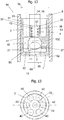
- Fig. 12 a bottom delimited by the cylindrical section 38, which contains an opening 43. This opening 43 can in particular be arranged rotationally symmetrically about the central axis 60.
- Fig. 11 shows a view of the check valve 10 according to Fig. 10 seen from the outflow side of the valve, that is, from the second section 52 of the channel 5.
- the channel 5 is in the Fig. 11 omitted, Fig. 11 consequently shows a view of the sleeve 3.
- Fig. 12 shows a first view of a check valve 10 according to a fifth embodiment in a partially sectioned view.
- the check valve 10 is for Recording in a channel 5 through which a fluid flows.
- the channel 5 has a first channel section 51 and a second channel section 52.
- a shoulder 53 is arranged between the first channel section 51 and the second channel section 52.
- the inside diameter of the first channel section 51 differs from the inside diameter of the second channel section 52, which is indicated in the present illustration by the external thread of the first jacket element 31 shown in section.
- the shoulder 53 can be formed by the thread runout.
- the check valve 10 comprises a valve seat element 1, a valve body 2 and a sleeve 3.
- the valve body 2 can be moved in the sleeve 3 such that it rests on the valve seat element 1 in a first position and in a second position at a distance from the valve seat element 1 is arranged.
- the valve seat element 1 has a bore 11 which can be closed by the valve body 2 in the first position.
- a spring element 4 is arranged between the valve body 2 and the sleeve 3.
- the spring element 4 has a first end 41 and a second end 42.
- the valve body 2 is held in the first position by the spring element 4, as long as the fluid pressure present in the bore 11 is less than the closing force of the spring element 4 and possibly the dead weight of the valve body 2.
- the first end 41 of the spring element 4 is connected to the valve body 2.
- the sleeve 3 has a first jacket element 31 which is intended to be received in the channel 5.
- the casing element 31 has an external thread which engages in an internal thread located on the inner wall of the first section 51 of the channel 5.
- the first casing element 31 has in particular an outer diameter 35 which essentially corresponds to the inner diameter of the first section 51 of the channel 5.
- the sleeve 3 has a second jacket element 32, which is intended for receiving the second end 42 of the spring element 4.
- the second end 42 of the spring element 4 is held in a recess 33 in the second jacket element 32.
- the second casing element 32 thus forms a cage in which the valve body 2 can be moved.
- the first jacket element 31 can be connected to the second jacket element 32 via a connecting element 132.
- the connecting element 132 has a shoulder which is designed to receive the valve seat element 1.
- the valve seat element 1 is designed as a cap-shaped element which contains the bore 11.
- the valve seat element 1 has a circumferential edge which can be plugged or screwed onto the shoulder of the connecting element 132.
- the edge can contain an internal thread, which with a corresponding external thread of the connecting element 132 can be engaged.
- the connection between the edge and the heel can also be obtained by a press fit.
- valve seat element 1 has a second surface 13 opposite the first surface 12.
- the second jacket element 32 can have a maximum outside diameter 34 that is smaller than the maximum outside diameter 35 of the first jacket element 31.
- the outside diameter 36 of the recess 33 is in particular smaller than the maximum outside diameter 35.
- the second jacket element 32 has Fig. 12 a first cylindrical section 37 and a second cylindrical section 38.
- the sleeve 3 contains a connecting element 132, which connects the first jacket element 31 to the second jacket element 32.
- the first cylindrical section 37 is arranged in the connecting element 132.
- the first cylindrical section 37 forms a central bore for receiving the valve body 2. Since the diameter of the spring element 4 is smaller than the diameter 21 of the valve body 2, the inside diameter of the second cylindrical section 38 is smaller than the inside diameter of the first cylindrical section 37.
- the inner surface of the conical transition piece can serve as a bearing surface for the valve body 2 when the valve body 2 is in the open position.
- the fluid flows from the cavity 50 past the underside of the valve body into the openings 40, from where it reaches the first section 51 of the channel 5.
- the direction of flow of the fluid is thus the direction of flow of the fluid in 10, 11 opposed. It is therefore a check valve for a backward fluid flow.
- the sleeve 3, in particular the connecting element 132, can contain a plurality of openings 40. According to the present exemplary embodiment, six openings 40 are provided, which in FIG Fig. 13 is visible. The openings 40 are in particular of the same size.
- a fluid can flow through the openings 40 when the valve body 2 is separated from the valve seat element 1. If the valve body 2 by the pressure of the inflowing fluid is lifted from the valve seat element 1, the spring element 4 is compressed. The valve body 2 is guided in the first cylindrical section 37 in the second jacket element 32 or in the connecting element 132.
- the valve body 2 is in particular designed as a spherical valve body.
- the first end 41 of the spring element 4 lies on the surface of the valve body 2.
- the first cylindrical section 37 has an inner diameter 39 which corresponds at least to the outer diameter 21 of the valve body 2.
- the cavity 50 is connected to a plurality of openings 40.
- the bore 11 is connected to the cavity 50 when the valve body 2 does not close the bore 11. A fluid flowing through the bore flows through the bore 11 into the cavity 50 and is guided through the cavity 50 to the openings 40, from where it reaches the first section 51 of the channel 5.
- the cross-sectional area of the cavity 50 is larger than the cross-sectional area of the bore 11, so that the fluid can spread quickly in the cavity. Therefore, the check valve according to the invention can surprisingly switch much more quickly from the closed state to the open state than conventional check valves.
- a check valve according to the invention thus has a significantly shorter reaction time than conventional check valves, so that a significantly shorter changeover phase is made possible.
- the cylindrical section 38 is designed in particular as a jacket element of the recess 33.
- the recess 33 can be formed from a plurality of strut-shaped elements which extend from the connecting element 132 to the end of the recess 33, which is not shown in the drawings.
- Fig. 12 a bottom delimited by the cylindrical section 38, which contains an opening 43. This opening 43 can in particular be arranged rotationally symmetrically about the central axis 60.
- the second jacket element 32 can also have a polygonal, in particular quadrangular, cross section.
Description
Gegenstand der Erfindung ist ein Rückschlagventil. Dieses Rückschlagventil wird vormontiert und als vormontierter Bausatz in eine entsprechende Bohrung eingebracht, die einen Kanal für ein Fluid, das heisst ein Gas oder eine Flüssigkeit enthält.The invention relates to a check valve. This check valve is preassembled and inserted as a preassembled kit in a corresponding bore which contains a channel for a fluid, that is to say a gas or a liquid.
Die
Beispielsweise ist in der
Allen diesen vorbekannten Lösungen ist gemeinsam, dass sie entweder aus einer Vielzahl von Bauteilen bestehen oder nicht vormontiert in eine Bohrung eingebracht werden können. Daher besteht ein Bedarf nach einem Rückschlagventil, welches einen einfachen Aufbau hat, das heisst aus wenigen Einzelteilen besteht, die derart vormontiert werden, dass sie am gewünschten Einsatzort in einem einzigen Arbeitsschritt zusammengebaut werden können.All these previously known solutions have in common that they either consist of a large number of components or cannot be pre-assembled in a bore. There is therefore a need for a check valve which has a simple structure, that is to say consists of a few individual parts which are preassembled in such a way that they can be assembled at the desired place of use in a single work step.
Nachteilig an der in der
Aus der
Eine Aufgabe der Erfindung ist es, ein Rückschlagventil zu konzipieren, welches einfach herstellbar und in einem einzigen Arbeitsschritt einfach in einen fluidführenden Kanal einbaubar ist. Eine weitere Aufgabe der Erfindung ist es, ein Rückschlagventil bereitzustellen, welches in vormontiertem Zustand in eine Bohrung eingebaut werden kann. Eine weitere Aufgabe der Erfindung ist es, ein Rückschlagventil mit einer geringen Einbaulänge vorzusehen, welches einen möglichst niedrigen Druckverlust aufweist.An object of the invention is to design a check valve that is easy to manufacture and can be easily installed in a fluid-carrying channel in a single step. Another object of the invention is to provide a check valve which can be installed in a bore in a preassembled state. Another object of the invention is to provide a check valve with a small installation length, which has the lowest possible pressure loss.
Die Lösung der Aufgaben der Erfindung erfolgt durch die Merkmale des Anspruchs 1. Weitere vorteilhafte Ausführungen sind Gegenstand der Ansprüche 2 bis 13.The objects of the invention are achieved by the features of
Wenn der Begriff "beispielsweise" in der nachfolgenden Beschreibung verwendet wird, bezieht sich dieser Begriff auf Ausführungsbeispiele und/oder Ausführungsformen, was nicht notwendigerweise als eine bevorzugtere Anwendung der Lehre der Erfindung zu verstehen ist. In ähnlicher Weise sind die Begriffe "vorzugsweise", "bevorzugt" zu verstehen, indem sie sich auf ein Beispiel aus einer Menge von Ausführungsbeispielen und/oder Ausführungsformen beziehen, was nicht notwendigerweise als eine bevorzugte Anwendung der Lehre der Erfindung zu verstehen ist. Dementsprechend können sich die Begriffe "beispielsweise", "vorzugsweise" oder "bevorzugt" auf eine Mehrzahl von Ausführungsbeispielen und/oder Ausführungsformen beziehen.When the term "for example" is used in the following description, this term refers to exemplary embodiments and / or embodiments, which is not necessarily to be understood as a more preferred application of the teaching of the invention. Similarly, the terms "preferred", "preferred" are to be understood to refer to an example from a set of embodiments and / or embodiments, which is not necessarily to be understood as a preferred application of the teaching of the invention. Accordingly, the terms can change "For example", "preferably" or "preferred" refer to a plurality of exemplary embodiments and / or specific embodiments.
Die nachfolgende detaillierte Beschreibung enthält verschiedene Ausführungsbeispiele für das erfindungsgemässe Rückschlagventil. In der Beschreibung und den Ansprüchen werden die Begriffe "enthalten", "umfassen", "aufweisen" als "enthalten, aber nicht beschränkt auf.." interpretiert.The following detailed description contains various exemplary embodiments for the check valve according to the invention. In the description and the claims, the terms “contain”, “comprise”, “have” are interpreted as “contain, but not limited to ..”.
Das Rückschlagventil zur Aufnahme in einem von einem Fluid durchströmbaren Kanal umfasst ein Ventilsitzelement, einen Ventilkörper, sowie eine Hülse, wobei der Ventilkörper in der Hülse derart bewegbar ist, dass er in einer ersten Position auf dem Ventilsitzelement aufliegt und in einer zweiten Position in einem Abstand vom Ventilsitzelement angeordnet ist. Das Ventilsitzelement weist eine Bohrung auf, die vom Ventilkörper in der ersten Position verschliessbar ist, wobei zwischen dem Ventilkörper und der Hülse ein Federelement angeordnet ist. Das Federelement weist ein erstes Ende und ein zweites Ende auf. Der Ventilkörper ist durch das Federelement in der ersten Position gehalten, solange der in der Bohrung anliegende Fluiddruck kleiner als die Schliesskraft des Federelements ist. Das erste Ende des Federelements ist mit dem Ventilkörper verbunden. Die Hülse weist ein erstes Mantelelement auf, welches zur Aufnahme im Kanal bestimmt ist. Die Hülse weist ein zweites Mantelelement auf, welches zur Aufnahme des zweiten Endes des Federelements bestimmt ist. Das Federelement ist in einer topfförmigen Ausnehmung des zweiten Mantelelements gehalten. Das heisst, dass das Federelement sich innerhalb des Mantels der topfförmigen Ausnehmung befindet. Hierdurch kann das Federelement entlang der Innenwand des Mantels der topfförmigen Ausnehmung geführt werden, sodass ein sich entlang fast der gesamten Länge des Federelements erstreckender Führungszapfen nicht erforderlich ist, wie er beispielsweise in der
Nach einem Ausführungsbeispiel weist das erste Mantelelement einen Aussendurchmesser auf, welcher im Wesentlichen dem Innendurchmesser des Kanals entspricht. Das zweite Mantelelement kann einen maximalen Aussendurchmesser aufweisen, der kleiner als der maximale Aussendurchmesser des ersten Mantelelements ist. Der Aussendurchmesser der topfförmigen Ausnehmung kann kleiner sein als der maximale Aussendurchmesser.According to one exemplary embodiment, the first jacket element has an outside diameter which essentially corresponds to the inside diameter of the channel. The second jacket element can have a maximum outside diameter that is smaller than the maximum outside diameter of the first jacket element. The outside diameter of the cup-shaped recess can be smaller than the maximum outside diameter.
Das zweite Mantelelement weist nach einem Ausführungsbeispiel einen ersten zylinderförmigen Abschnitt und einen zweiten zylinderförmigen Abschnitt auf, wobei der zweite zylinderförmige Abschnitt als ein Mantelelement der topfförmigen Ausnehmung ausgebildet ist. Der erste zylinderförmige Abschnitt kann einen Inndurchmesser aufweisen, der mindestens dem Aussendurchmesser des Ventilkörpers entspricht. Die Hülse kann eine Öffnung enthalten, die im zweiten Mantelelement angeordnet ist.According to one exemplary embodiment, the second jacket element has a first cylindrical section and a second cylindrical section, the second cylindrical section being designed as a jacket element of the cup-shaped recess. The first cylindrical section can have an inner diameter which corresponds at least to the outer diameter of the valve body. The sleeve can contain an opening which is arranged in the second jacket element.
Die Hülse enthält ein Verbindungselement, welches das erste Mantelelement mit dem zweiten Mantelelement verbindet.The sleeve contains a connecting element which connects the first jacket element to the second jacket element.
Nach einem Ausführungsbeispiel kann der Ventilkörper als ein kugelförmiger Ventilkörper ausgebildet sein. Insbesondere kann der Ventilkörper eine Ausnehmung zur Aufnahme des ersten Endes des Federelements aufweisen.According to one embodiment, the valve body can be designed as a spherical valve body. In particular, the valve body can have a recess for receiving the first end of the spring element.
Nach einem Ausführungsbeispiel ist das zweite Mantelelement im ersten Mantelelement aufgenommen. Das Verbindungselement kann ein Ende des ersten Mantelelements mit einem Ende des zweiten Mantelelements verbinden. Das Verbindungselement kann zwischen dem Ende des ersten Mantelelements und dem Ende des zweiten Mantelelements einen Absatz aufweisen. Der Absatz des Verbindungselements kann auf einen Absatz des Ventilsitzelements aufgesetzt werden oder in einer Ausnehmung oder Nut des Ventilsitzelements aufgenommen sein. Der Absatz des Verbindungselements ermöglicht eine Positionierung der Hülse bei der Montage des Rückschlagventils.According to one embodiment, the second jacket element is accommodated in the first jacket element. The connecting element can connect one end of the first jacket element to one end of the second jacket element. The connecting element can have a shoulder between the end of the first jacket element and the end of the second jacket element. The shoulder of the connecting element can be placed on a shoulder of the valve seat element or received in a recess or groove of the valve seat element. The shoulder of the connecting element enables the sleeve to be positioned when the check valve is installed.
Nach einem Ausführungsbeispiel ist das Verbindungselement zwischen dem ersten Mantelelement und dem zweiten Mantelelement angeordnet. Das Ventilsitzelement kann innerhalb des ersten Mantelelements angeordnet sein und auf dem Verbindungselement positioniert werden. Gemäss diesem Ausführungsbeispiel ist es möglich, das Ventilsitzelement bei der Montage des Rückschlagventils auf dem Ventilkörper zu positionieren, sodass der Ventilkörper verliersicher im zweiten Mantelelement gehalten werden kann.According to one embodiment, the connecting element is arranged between the first jacket element and the second jacket element. The valve seat element can be arranged within the first casing element and positioned on the connecting element. According to this exemplary embodiment, it is possible to position the valve seat element on the valve body when the check valve is installed, so that the valve body can be held captively in the second jacket element.
Insbesondere sind nach jedem der vorhergehenden Ausführungsbeispiele die Hülse, das erste Mantelelement sowie das zweite Mantelelement als ein einziges Bauteil ausgebildet. Die Führung des Federelements sowie die Befestigung des Rückschlagventils im Kanal und die Verbindung mit dem Ventilsitzelement können somit durch ein einziges Bauteil, nämlich die Hülse, erreicht werden. Die Hülse kann beispielsweise mittels eines Spannelements im Kanal gehalten werden, alternativ oder in Kombination hierzu könnte sie auch durch einen Presssitz oder durch eine Schraubverbindung im Kanal gehalten werden.In particular, according to each of the preceding exemplary embodiments, the sleeve, the first jacket element and the second jacket element are designed as a single component. The guidance of the spring element as well as the fastening of the check valve in the channel and the connection to the valve seat element can thus be achieved by a single component, namely the sleeve. For example, the sleeve can be held in the channel by means of a tensioning element, alternatively or in combination, it could also be held in the channel by a press fit or by a screw connection.
Ein Vorteil der erfindungsgemässen Lösung insbesondere gemäss jedes der Ausführungsbeispiele besteht darin, dass der Einbau in den vom Fluid durchströmten Kanal in einem einzigen Arbeitsschritt vorgenommen werden kann, da das Rückschlagventil vormontiert in den Kanal eingeschoben werden kann, bis es auf einem in dem Kanal befindlichen Absatz aufliegt. Durch den im Kanal angeordneten Absatz ist die exakte Position des Rückschlagventils im Kanal festgelegt. Der Absatz des Kanals nimmt nach einem Ausführungsbeispiel das Ventilsitzelement auf, nach einem weiteren Ausführungsbeispiel das Verbindungselement der Hülse.An advantage of the solution according to the invention, in particular according to each of the exemplary embodiments, is that the installation in the channel through which the fluid flows can be carried out in a single working step, since the check valve can be inserted into the channel in a preassembled manner until it is on a shoulder located in the channel rests. The exact position of the check valve in the channel is determined by the step arranged in the channel. The shoulder of the channel receives the valve seat element according to one embodiment, the connecting element of the sleeve according to a further embodiment.
Nach einem Ausführungsbeispiel ist zwischen dem Ventilsitzelement und der Hülse ein Hohlraum angeordnet. Durch diesen Hohlraum ist es möglich, dass das Rückschlagventil schneller öffnet. Sobald die Bohrung im Ventilsitzelement geöffnet wird, kann das Fluid in den Hohlraum einströmen. Der Hohlraum erstreckt sich vorteilhafterweise über den gesamten Kanalquerschnitt abzüglich der Wandstärke der Hülse an dieser Stelle. Somit steht beim Abheben des Ventilkörpers sofort ein grosser Fluidquerschnitt zur Verfügung.According to one embodiment, a cavity is arranged between the valve seat element and the sleeve. This cavity allows the check valve to open faster. As soon as the bore in the valve seat element is opened, the fluid can flow into the cavity. The cavity advantageously extends over the entire channel cross-section minus the wall thickness of the sleeve at this point. A large fluid cross-section is thus immediately available when the valve body is lifted off.
Insbesondere kann der Hohlraum mit einer Mehrzahl von Öffnungen verbunden sein. Vom Hohlraum kann somit das Fluid ungehindert in die Öffnungen strömen, sodass ein geringerer Durchflusswiderstand und somit ein überraschend geringer Druckverlust im Vergleich zu herkömmlichen Ventilen erhältlich ist.In particular, the cavity can be connected to a plurality of openings. The fluid can thus flow unhindered into the openings from the cavity, so that a lower flow resistance and thus a surprisingly low pressure loss is available in comparison to conventional valves.
Insbesondere ist die Bohrung des Ventilsitzelements mit dem Hohlraum verbunden, wenn der Ventilkörper die Bohrung nicht verschliesst. Daher wird ein unmittelbares Einströmen des Fluids in den Hohlraum ermöglicht, wodurch das erfindungsgemässe Rückschlagventil unmittelbar nach dem Abheben des Ventilkörpers von der Bohrung von einer grösseren Durchflussmenge durchströmt werden kann, als die herkömmlichen Rückschlagventile.In particular, the bore of the valve seat element is connected to the cavity if the valve body does not close the bore. Therefore, a direct inflow of the fluid into the cavity is made possible, whereby the check valve according to the invention can flow through a larger flow rate than the conventional check valves immediately after the valve body has been lifted from the bore.
Dieser Vorteil ist insbesondere auch dadurch ermöglicht, dass die Querschnittsfläche des Hohlraums grösser als die Querschnittsfläche der Bohrung sein kann. Insbesondere kann die Querschnittsfläche des Hohlraums sich um mehr als 20% von der Querschnittsfläche der Bohrung unterscheiden. Nach einer besonders vorteilhaften Ausführungsform unterscheidet sich die Querschnittsfläche des Hohlraums um mehr als 30% von die Querschnittsfläche der Bohrung, das heisst, die Querschnittsfläche des Hohlraums ist mindestens 30% grösser als die Querschnittsfläche der Bohrung. Insbesondere kann die Querschnittsfläche des Hohlraums sich um mindestens 50% von der Querschnittsfläche der Bohrung unterscheiden. Das heisst, die Querschnittsfläche des Hohlraums ist gemäss diesem besonders bevorzugten Ausführungsbeispiel mindestens 50% grösser als die Querschnittsfläche der Bohrung.This advantage is made possible in particular by the fact that the cross-sectional area of the cavity can be larger than the cross-sectional area of the bore. In particular, the Cross-sectional area of the cavity differ from the cross-sectional area of the bore by more than 20%. According to a particularly advantageous embodiment, the cross-sectional area of the cavity differs by more than 30% from the cross-sectional area of the bore, that is to say the cross-sectional area of the cavity is at least 30% larger than the cross-sectional area of the bore. In particular, the cross-sectional area of the cavity can differ from the cross-sectional area of the bore by at least 50%. This means that the cross-sectional area of the cavity is, according to this particularly preferred exemplary embodiment, at least 50% larger than the cross-sectional area of the bore.
Das zweite Mantelelement und das Verbindungselement weisen einen ersten zylinderförmigen Abschnitt und einen zweiten zylinderförmigen Abschnitt auf, wobei der erste zylinderförmige Abschnitt eine zentrale Bohrung für die Aufnahme des Ventilkörpers ausbildet. Der Innendurchmesser des zweiten zylinderförmigen Abschnitts ist kleiner als der Innendurchmesser des ersten zylinderförmigen Abschnitts. Hierdurch ist eine exakte Führung sowohl des Federelements als auch des Ventilkörpers ermöglicht.The second jacket element and the connecting element have a first cylindrical section and a second cylindrical section, the first cylindrical section forming a central bore for receiving the valve body. The inside diameter of the second cylindrical section is smaller than the inside diameter of the first cylindrical section. This enables exact guidance of both the spring element and the valve body.
Zwischen dem ersten zylinderförmigen Abschnitt und dem zweiten zylinderförmigen Abschnitt ist ein konisches Übergangsstück ausgebildet. Die Innenfläche des konischen Übergangsstücks dient als Auflagefläche für den Ventilkörper, wenn sich der Ventilkörper in der Öffnungsposition befindet. Durch die Verwendung eines konischen Übergangsstücks wird eine selbstzentrierende Auflagefläche für den Ventilkörper geschaffen. Zudem wird eine zumindest linienförmige Berührung ermöglicht, sodass die Druck- und Stosskräfte, die vom Ventilkörper auf die Auflagefläche wirken, optimal verteilt werden, wodurch es zu keinem Verschleiss an der Auflagefläche kommen kann.A conical transition piece is formed between the first cylindrical section and the second cylindrical section. The inner surface of the conical transition piece serves as a bearing surface for the valve body when the valve body is in the open position. The use of a conical transition piece creates a self-centering contact surface for the valve body. In addition, an at least linear contact is made possible, so that the pressure and impact forces, which act on the bearing surface from the valve body, are optimally distributed, whereby there can be no wear on the bearing surface.
Nach einem Ausführungsbeispiel enthält das zweite Mantelelement oder das Verbindungselement eine Mehrzahl von Öffnungen, sodass das Fluid schnell aus dem Hohlraum abströmen kann.According to one exemplary embodiment, the second jacket element or the connecting element contains a plurality of openings, so that the fluid can flow out of the cavity quickly.
Nach einem Ausführungsbeispiel enthält zweite Mantelelement eine topfförmige Ausnehmung, welche eine axialsymmetrische Öffnung enthalten kann. Insbesondere kann die axialsymmetrische Öffnung einen Durchmesser aufweisen, der kleiner als der Innendurchmesser des Federelements ist.According to one embodiment, the second casing element contains a cup-shaped recess, which can contain an axially symmetrical opening. In particular, the axially symmetrical opening can have a diameter that is smaller than the inner diameter of the spring element.
Ein Rückschlagventil nach einem der vorhergehenden Ausführungsbeispiele kann in einem beliebigen System zur Leitung von Fluiden verwendet werden. Insbesondere kann ein Rückschlagventil in Fluidfördersystemen verwendet werden, beispielsweise in Systemen, die eine Pumpe enthalten oder in Systemen, in welchen ein Fluiddruck aufgebaut werden soll. Ein derartiges Rückschlagventil kann auch als Überdruckventil verwendet werden. Das Rückschlagventil kann beispielsweise als Hydraulikventil zum Einsatz kommen. Weitere Einsatzmöglichkeiten eines derartigen Rückschlagventils finden sich im Betrieb von Brennkraftmaschinen, insbesondere in der Versorgung derselben mit Kühlflüssigkeiten, Schmiermitteln oder Brennstoffen.A check valve according to one of the preceding exemplary embodiments can be used in any system for conveying fluids. In particular, a check valve can be used in fluid delivery systems, for example in systems that contain a pump or in systems in which a fluid pressure is to be built up. Such a check valve can also be used as a pressure relief valve. The check valve can be used, for example, as a hydraulic valve. Further possible uses of such a check valve can be found in the operation of internal combustion engines, in particular in the supply of the same with coolants, lubricants or fuels.
Nachfolgend wird das erfindungsgemässe Rückschlagventil anhand einiger Ausführungsbeispiele dargestellt. Es zeigen
-
Fig. 1 einen Axialschnitt durch ein Rückschlagventil nach einem ersten Ausführungsbeispiel, -
Fig. 2 einen Radialschnitt durch das Rückschlagventil nach dem ersten Ausführungsbeispiel entlang der Schnittlinie A-A, -
Fig. 3 einen Radialschnitt durch das Rückschlagventil nach dem ersten Ausführungsbeispiel entlang der Schnittlinie B-B, -
Fig. 4 einen Radialschnitt durch das Rückschlagventil nach dem ersten Ausführungsbeispiel entlang der Schnittlinie C-C, -
Fig. 5 einen Axialschnitt durch ein Rückschlagventil nach einem zweiten Ausführungsbeispiel, -
Fig. 6 einen Radialschnitt durch das Rückschlagventil nach dem zweiten Ausführungsbeispiel entlang der Schnittlinie A-A, -
Fig. 7 einen Radialschnitt durch das Rückschlagventil nach dem zweiten Ausführungsbeispiel entlang der Schnittlinie B-B, -
Fig. 8 einen Radialschnitt durch das Rückschlagventil nach dem zweiten Ausführungsbeispiel entlang der Schnittlinie C-C, -
Fig. 9 einen Axialschnitt eines Rückschlagventils nach einem dritten Ausführungsbeispiel, -
Fig. 10 einen Axialschnitt durch ein Rückschlagventil nach einem vierten Ausführungsbeispiel, -
Fig. 11 eine Ansicht auf das Rückschlagventil nach dem vierten Ausführungsbeispiel, -
Fig. 12 einen Axialschnitt durch ein Rückschlagventil nach einem fünften Ausführungsbeispiel, -
Fig. 13 eine Ansicht auf das Rückschlagventil nach dem fünften Ausführungsbeispiel.
-
Fig. 1 3 shows an axial section through a check valve according to a first exemplary embodiment, -
Fig. 2 3 shows a radial section through the check valve according to the first exemplary embodiment along the section line AA, -
Fig. 3 3 shows a radial section through the check valve according to the first exemplary embodiment along the section line BB, -
Fig. 4 3 shows a radial section through the check valve according to the first exemplary embodiment along the section line CC, -
Fig. 5 3 shows an axial section through a check valve according to a second exemplary embodiment, -
Fig. 6 3 shows a radial section through the check valve according to the second exemplary embodiment along the section line AA, -
Fig. 7 3 shows a radial section through the check valve according to the second exemplary embodiment along the section line BB, -
Fig. 8 3 shows a radial section through the check valve according to the second exemplary embodiment along the section line CC, -
Fig. 9 3 shows an axial section of a check valve according to a third exemplary embodiment, -
Fig. 10 3 shows an axial section through a check valve according to a fourth exemplary embodiment, -
Fig. 11 2 shows a view of the check valve according to the fourth exemplary embodiment, -
Fig. 12 3 shows an axial section through a check valve according to a fifth exemplary embodiment, -
Fig. 13 a view of the check valve according to the fifth embodiment.
Die Hülse 3 weist ein zweites Mantelelement 32 auf, welches zur Aufnahme des zweiten Endes 42 des Federelements 4 bestimmt ist. Das zweite Ende 42 des Federelements 4 ist in einer topfförmigen Ausnehmung 33 des zweiten Mantelelements 32 gehalten. Das zweite Mantelelement 32 bildet somit einen Käfig aus, in welchem der Ventilkörper 2 bewegbar ist. Das erste Mantelelement 31 kann über ein Verbindungselement 132 mit dem zweiten Mantelelement 32 verbunden sein. Das Verbindungselement 132 kann auf einer ersten Oberfläche 12 des Ventilsitzelementelements 1 angeordnet sein. Das Ventilsitzelement 1 weist eine der ersten Oberfläche 12 gegenüberliegende zweite Oberfläche 13 auf. Die zweite Oberfläche 13 liegt teilweise auf dem Absatz 53 auf.The
Das zweite Mantelelement 32 kann einen maximalen Aussendurchmesser 34 aufweisen, der kleiner als der maximale Aussendurchmesser 35 des ersten Mantelelements 31 ist. Der Aussendurchmesser 36 der topfförmigen Ausnehmung 33 ist insbesondere kleiner als der maximale Aussendurchmesser 35.The
Das zweite Mantelelement 32 weist nach dem Ausführungsbeispiel gemäss
Die Hülse 3 enthält ein Verbindungselement 132, welches das erste Mantelelement 31 mit dem zweiten Mantelelement 32 verbindet.The
Der zylinderförmige Abschnitt 38 ist insbesondere als ein Mantelelement der topfförmigen Ausnehmung 33 ausgebildet. Die topfförmige Ausnehmung kann durch ein nicht dargestelltes Ausführungsbeispiel aus einer Mehrzahl von strebenförmigen Elementen gebildet sein, welche sich vom Verbindungselement 132 bis zum Ende der topfförmigen Ausnehmung 33 erstrecken.The
Der erste zylinderförmige Abschnitt 37 weist gemäss diesem Ausführungsbeispiel einen Innendurchmesser 39 auf, der mindestens dem Aussendurchmesser 21 des Ventilkörpers 2 entspricht.According to this exemplary embodiment, the first
In
Die Hülse 3 weist ein zweites Mantelelement 32 auf, welches zur Aufnahme des zweiten Endes 42 des Federelements 4 bestimmt ist. Das zweite Ende 42 des Federelements 4 ist in einer topfförmigen Ausnehmung 33 des zweiten Mantelelements 32 gehalten. Das zweite Mantelelement 32 bildet somit einen Käfig aus, in welchem der Ventilkörper 2 bewegbar ist. Das erste Mantelelement 31 kann über ein Verbindungselement 132 mit dem zweiten Mantelelement 32 verbunden sein. Das Verbindungselement 132 kann auf einer ersten Oberfläche 12 des Ventilsitzelements 1 angeordnet sein. Das Ventilsitzelement 1 weist eine der ersten Oberfläche 12 gegenüberliegende zweite Oberfläche 13 auf. Die erste Oberfläche 12 liegt auf dem Verbindungselement 132 auf und ist in dem ersten Mantelelement 31 der Hülse 3 aufgenommen. Das Verbindungselement 132 liegt auf der dem Ventilsitzelement 1 gegenüberliegenden Seite teilweise auf dem Absatz 53 auf.The
Das zweite Mantelelement 32 kann einen maximalen Aussendurchmesser 34 (siehe
Das zweite Mantelelement 32 weist nach dem Ausführungsbeispiel gemäss
Die Hülse 3 enthält ein Verbindungselement 132, welches das erste Mantelelement 31 mit dem zweiten Mantelelement 32 verbindet. Die Strömung des Fluids erfolgt im Kanal 5 vom ersten Abschnitt 51 zum zweiten Abschnitt 52, in der Zeichnung nach unten. Das erste Mantelelement 31 erstreckt sich gemäss diesem Ausführungsbeispiel stromaufwärts des Verbindungselements 132. Das Ventilsitzelement 1 ist innerhalb des ersten Mantelelements 31 angeordnet und liegt auf dem Verbindungselement 132 auf.The
Das zweite Mantelelement 32 erstreckt sich stromabwärts des Verbindungselements 132. Der zylinderförmige Abschnitt 38 des zweiten Mantelelements 32 ist insbesondere als ein Mantelelement der topfförmigen Ausnehmung 33 ausgebildet. Die topfförmige Ausnehmung 33 kann durch ein nicht dargestelltes Ausführungsbeispiel aus einer Mehrzahl von strebenförmigen Elementen gebildet sein, welche sich vom Verbindungselement 132 bis zum Ende der topfförmigen Ausnehmung 33 erstrecken. Der erste zylinderförmige Abschnitt 37 weist gemäss diesem Ausführungsbeispiel einen Innendurchmesser 39 (siehe
Der Kanal 5 enthält die Hülse 3, die das Ventilsitzelement 1 enthält, das als ringförmiges Scheibenelement ausgebildet ist. Das ringförmige Scheibenelement enthält eine mittige Bohrung 11, die sich entlang der Mittenachse 60 des Kanals 5 erstreckt. Durch diese Bohrung 11 gelangt das Fluid auf die Oberfläche des die Bohrung 11 normalerweise verschliessenden Ventilkörpers 2. Bei genügendem Fluiddruck wird der Ventilkörper 2 von der Bohrung 11 abgehoben, sodass sich ein ringförmiger Spalt ausbildet, durch welchen das Fluid in den Zwischenraum zwischen dem zweiten Abschnitt 52 des Kanals 5 und dem zweiten Mantelelement 32 einströmen kann, siehe hierzu
Die Hülse 3 weist ein zweites Mantelelement 32 auf, welches zur Aufnahme des zweiten Endes 42 des Federelements 4 bestimmt ist. Das zweite Ende 42 des Federelements 4 ist in einer topfförmigen Ausnehmung 33 des zweiten Mantelelements 32 gehalten. Das zweite Mantelelement 32 bildet somit einen Käfig aus, in welchem der Ventilkörper 2 bewegbar ist. Das erste Mantelelement 31 kann über ein Verbindungselement 132 mit dem zweiten Mantelelement 32 verbunden sein. Das Verbindungselement 132 ist gemäss diesem Ausführungseispiel in einem Abstand zur ersten Oberfläche 12 des Ventilsitzelements 1 angeordnet. Auf der ersten Oberfläche 12 stützt sich ein Fortsatz 133 des ersten Mantelelements 131 ab. Von dem Fortsatz 133, der ersten Oberfläche 12 des Ventilsitzelements 1 sowie dem Verbindungselement 132 wird somit eine Öffnung begrenzt, welche vom Fluid durchströmt wird, sobald der Ventilkörper 2 vom Ventilsitz 14 getrennt wird. Das Fluid kann am Ventilkörper 2 in die Öffnung strömen und gelangt in die Öffnungen 131. Hierdurch wird ein grosser Strömungsquerschnitt bereits bei Eintritt des Fluids in die Öffnungen 131 bereitgestellt, sodass Druckverluste an dieser Stelle nur in sehr geringem Ausmass auftreten. Insbesondere sind die Druckverluste im Vergleich zu den vorhergehenden Ausführungsbeispielen nochmals vermindert. Der Hauptdruckverlust ist durch die Bohrung 11 bedingt, in welcher der Ventilkörper 3 in geschlossenem Zustand gehalten ist.The
Das Ventilsitzelement 1 weist eine der ersten Oberfläche 12 gegenüberliegende zweite Oberfläche 13 auf. Die zweite Oberfläche 13 bildet eine der Fluidströmung zugewendete Oberfläche aus. Die Strömungsrichtung ist somit in der Zeichnung von unten nach oben parallel zur Mittenachse 60.The
Das zweite Mantelelement 32 kann einen maximalen Aussendurchmesser aufweisen, der kleiner als der maximale Aussendurchmesser 35 des ersten Mantelelements 31 ist. In der vorliegenden Darstellung ist anstelle des Aussendurchmessers der Radius 134 des zweiten Mantelelements gezeigt, da der Durchmesser durch die rechtsseitige Öffnung 131 nicht darstellbar ist. Dasselbe gilt für den Aussendurchmesser 36 (siehe
Das zweite Mantelelement 32 weist nach dem Ausführungsbeispiel gemäss
Die Strömung des Fluids erfolgt im Kanal 5 vom zweiten Abschnitt 52 zum ersten Abschnitt 51 in der Zeichnung nach oben. Das erste Mantelelement 31 erstreckt sich bis auf den Fortsatz 133 gemäss diesem Ausführungsbeispiel stromabwärts des Verbindungselements 132. Das zweite Mantelelement 32 erstreckt sich stromabwärts des Verbindungselements 132. Der zylinderförmige Abschnitt 38 des zweiten Mantelelements 32 ist insbesondere als ein Mantelelement der topfförmigen Ausnehmung 33 ausgebildet. Die topfförmige Ausnehmung 33 kann durch ein nicht dargestelltes Ausführungsbeispiel aus einer Mehrzahl von strebenförmigen Elementen gebildet sein, welche sich vom Verbindungselement 132 bis zum Ende der topfförmigen Ausnehmung 33 erstrecken. Der erste zylinderförmige Abschnitt 37 weist gemäss diesem Ausführungsbeispiel einen Innendurchmesser 39 (siehe
Die Hülse 3 enthält das Verbindungselement 132, welches das erste Mantelelement 31 mit dem zweiten Mantelelement 32 verbindet. Insbesondere sind nach jedem der vorhergehenden Ausführungsbeispiele die Hülse 3, das erste Mantelelement 31 sowie das zweite Mantelelement 32 als ein einziges Bauteil ausgebildet. Die Hülse 3 kann zumindest eines der Elemente Kunststoff oder Metall enthalten. Als Kunststoffbauteil kann die Hülse 3 beispielsweise im Spritzgiessverfahren hergestellt sein. Wenn die Hülse 3 aus Metall besteht, kann sie insbesondere durch ein Umformverfahren hergestellt sein, wobei die Öffnungen 131 nach dem Umformen erzeugt werden können. Die Öffnungen können beispielsweise gebohrt, geschnitten, gestanzt oder gefräst werden.The
Nach jedem der vorhergehenden Ausführungsbeispiele kann durch das Spannelement 6 ein Verpressen der Hülse 3 derart erfolgen, dass sich die Hülse, also insbesondere die Aussenwand des ersten Mantelelements 31 in der den Abschnitt 51 ausbildenden Bohrung verbeisst. Insbesondere kann die Hülse 3 mindestens einen Vorsprung, beispielsweise eine zahnartige Rille aufweisen. Dieser Vorsprung kann insbesondere an der Aussenwand des ersten Mantelelements 31 angebracht sein, was in den Figuren nicht zeichnerisch dargestellt ist. Das Rückschlagventil kann auch bei Drücken, die mehr als 1000 bar betragen, sicher im Kanal 5 gehalten werden.According to each of the preceding exemplary embodiments, the clamping
Das Rückschlagventil 10 umfasst ein Ventilsitzelement 1, einen Ventilkörper 2, sowie eine Hülse 3. Der Ventilkörper 2 ist in der Hülse 3 derart bewegbar, dass er in einer ersten Position auf dem Ventilsitzelement 1 aufliegt und in einer zweiten Position in einem Abstand vom Ventilsitzelement 1 angeordnet ist. Das Ventilsitzelement 1 weist eine Bohrung 11 auf, die vom Ventilkörper 2 in der ersten Position verschliessbar ist. Zwischen dem Ventilkörper 2 und der Hülse 3 ist ein Federelement 4 angeordnet. Das Federelement 4 weist ein erstes Ende 41 und ein zweites Ende 42 auf. Der Ventilkörper 2 ist durch das Federelement 4 in der ersten Position gehalten, solange der in der Bohrung 11 anliegende Fluiddruck kleiner als die Schliesskraft des Federelements 4 und gegebenenfalls das Eigengewicht des Ventilkörpers 2 ist. In der ersten Position versperrt der Ventilkörper 2 die Bohrung 11, sodass ein Durchtritt eines Fluids verhindert ist. Das erste Ende 41 des Federelements 4 ist mit dem Ventilkörper 2 verbunden. Die Hülse 3 weist ein erstes Mantelelement 31 auf, welches zur Aufnahme im Kanal 5 bestimmt ist. Das Mantelelement 31 weist gemäss diesem Ausführungsbeispiel ein Aussengewinde auf, welches in ein an der Innenwand des ersten Abschnitts 51 des Kanals 5 befindliches Innengewinde eingreifen kann, was zeichnerisch nicht dargestellt ist.The
Das erste Mantelelement 31 weist insbesondere einen Aussendurchmesser 35 auf, welcher im Wesentlichen dem Innendurchmesser des ersten Abschnitts 51 des Kanals 5 entspricht.The
Die Hülse 3 weist ein zweites Mantelelement 32 auf, welches zur Aufnahme des zweiten Endes 42 des Federelements 4 bestimmt ist. Das zweite Ende 42 des Federelements 4 ist in einer Ausnehmung 33 des zweiten Mantelelements 32 gehalten. Das zweite Mantelelement 32 bildet somit einen Käfig aus, in welchem der das Federelement 4 bewegbar ist. Das erste Mantelelement 31 kann über ein Verbindungselement 132 mit dem zweiten Mantelelement 32 verbunden sein. Das Verbindungselement 132 weist einen Absatz 142 auf, der zur Aufnahme des Ventilsitzelements 1 ausgebildet ist. Das Ventilsitzelement 1 ist als ein ringförmiges Element ausgebildet, welches die Bohrung 11 enthält. Das Ventilsitzelement 1 weist eine der ersten Oberfläche 12 gegenüberliegende zweite Oberfläche 13 aufThe
Zwischen der ersten Oberfläche 12 des Ventilsitzelements 1 und der gegenüberliegenden Stirnfläche des Verbindungselements 132 ist ein Abstand vorgesehen. Durch diesen Abstand wird zwischen Ventilsitzelement 1 und der Hülse 3, insbesondere dem Verbindungselement 132 ein Hohlraum 50 gebildet, der im Betrieb mit Fluid befüllbar ist.A distance is provided between the
Das zweite Mantelelement 32 kann einen maximalen Aussendurchmesser 34 aufweisen, der kleiner als der maximale Aussendurchmesser 35 des ersten Mantelelements 31 ist. Der Aussendurchmesser 36 der Ausnehmung 33 ist insbesondere kleiner als der maximale Aussendurchmesser 35.The
Das zweite Mantelelement 32 weist nach dem Ausführungsbeispiel gemäss
Die Hülse 3, insbesondere das Verbindungselement 132, kann eine Mehrzahl von Öffnungen 40 enthalten. Die Öffnungen können im konischen Übergangsstück angeordnet sein, sie können aber auch als Schlitze oder Ausnehmungen in zumindest einem der ersten oder zweiten zylinderförmigen Abschnitte 37, 38 angeordnet sein. Gemäss dem vorliegenden Ausführungsbeispiel sind sechs Öffnungen 40 vorgesehen, was in
Der Hohlraum 50 ist mit einer Mehrzahl von Öffnungen 40 verbunden. Die Bohrung 11 ist mit dem Hohlraum 50 verbunden, wenn der Ventilkörper 2 die Bohrung 11 nicht verschliesst. Ein durch die Bohrung einströmendes Fluid fliesst durch die Bohrung 11 in den Hohlraum 50 und wird durch den Hohlraum 50 zu den Öffnungen 40 geführt, von wo es in den zweiten Abschnitt 52 des Kanals 5 gelangt.The
Die Querschnittsfläche des Hohlraums 50 ist grösser als die Querschnittsfläche der Bohrung 11, sodass sich das Fluid schnell im Hohlraum 50 ausbreiten kann. Daher kann das erfindungsgemässe Rückschlagventil überraschenderweise viel schneller vom geschlossenen Zustand in den geöffneten Zustand umschalten als herkömmliche Rückschlagventile. Ein erfindungsgemässes Rückschlagventil weist somit eine wesentlich geringere Reaktionszeit auf als herkömmliche Rückschlagventile, sodass eine wesentlich verkürzte Umschaltphase ermöglicht ist.The cross-sectional area of the
Der zylinderförmige Abschnitt 38 ist insbesondere als ein Mantelelement der Ausnehmung 33 ausgebildet. Die Ausnehmung 33 kann aus einer Mehrzahl von strebenförmigen Elementen gebildet sein, welche sich vom Verbindungselement 132 bis zum Ende der Ausnehmung 33 erstrecken, was in den Zeichnungen nicht dargestellt ist. Die Ausnehmung weist gemäss
Das Rückschlagventil 10 umfasst ein Ventilsitzelement 1, einen Ventilkörper 2, sowie eine Hülse 3. Der Ventilkörper 2 ist in der Hülse 3 derart bewegbar, dass er in einer ersten Position auf dem Ventilsitzelement 1 aufliegt und in einer zweiten Position in einem Abstand vom Ventilsitzelement 1 angeordnet ist. Das Ventilsitzelement 1 weist eine Bohrung 11 auf, die vom Ventilkörper 2 in der ersten Position verschliessbar ist. Zwischen dem Ventilkörper 2 und der Hülse 3 ist ein Federelement 4 angeordnet. Das Federelement 4 weist ein erstes Ende 41 und ein zweites Ende 42 auf. Der Ventilkörper 2 ist durch das Federelement 4 in der ersten Position gehalten, solange der in der Bohrung 11 anliegende Fluiddruck kleiner als die Schliesskraft des Federelements 4 und gegebenenfalls das Eigengewicht des Ventilkörpers 2 ist. Das erste Ende 41 des Federelements 4 ist mit dem Ventilkörper 2 verbunden. Die Hülse 3 weist ein erstes Mantelelement 31 auf, welches zur Aufnahme im Kanal 5 bestimmt ist. Das Mantelelement 31 weist gemäss diesem Ausführungsbeispiel ein Aussengewinde auf, welches in ein an der Innenwand des ersten Abschnitts 51 des Kanals 5 befindliches Innengewinde eingreift. Das erste Mantelelement 31 weist insbesondere einen Aussendurchmesser 35 auf, welcher im Wesentlichen dem Innendurchmesser des ersten Abschnitts 51 des Kanals 5 entspricht.The
Die Hülse 3 weist ein zweites Mantelelement 32 auf, welches zur Aufnahme des zweiten Endes 42 des Federelements 4 bestimmt ist. Das zweite Ende 42 des Federelements 4 ist in einer Ausnehmung 33 des zweiten Mantelelements 32 gehalten. Das zweite Mantelelement 32 bildet somit einen Käfig aus, in welchem der Ventilkörper 2 bewegbar ist. Das erste Mantelelement 31 kann über ein Verbindungselement 132 mit dem zweiten Mantelelement 32 verbunden sein. Das Verbindungselement 132 weist einen Absatz auf, der zur Aufnahme des Ventilsitzelements 1 ausgebildet ist. Das Ventilsitzelement 1 ist als ein kappenförmiges Element ausgebildet, welches die Bohrung 11 enthält. Das Ventilsitzelement 1 weist einen umlaufenden Rand auf, welcher auf den Absatz des Verbindungselements 132 aufgesteckt oder aufgeschraubt werden kann. Der Rand kann ein Innengewinde enthalten, welches mit einem entsprechenden Aussengewinde des Verbindungselements 132 in Eingriff bringbar ist. Die Verbindung zwischen Rand und Absatz kann auch durch einen Presssitz erhalten werden.The
Zwischen der ersten Oberfläche 12 des Ventilsitzelements 1 und der gegenüberliegenden Stirnfläche des Verbindungselements 132 ist ein Abstand vorgesehen. Durch diesen Abstand wird zwischen Ventilsitzelement 1 und der Hülse 3, insbesondere dem Verbindungselement 132 ein Hohlraum gebildet, der im Betrieb mit Fluid befüllbar ist. Das Ventilsitzelement 1 weist eine der ersten Oberfläche 12 gegenüberliegende zweite Oberfläche 13 auf.A distance is provided between the
Das zweite Mantelelement 32 kann einen maximalen Aussendurchmesser 34 aufweisen, der kleiner als der maximale Aussendurchmesser 35 des ersten Mantelelements 31 ist. Der Aussendurchmesser 36 der Ausnehmung 33 ist insbesondere kleiner als der maximale Aussendurchmesser 35.The
Das zweite Mantelelement 32 weist nach dem Ausführungsbeispiel gemäss
Die Hülse 3, insbesondere das Verbindungselement 132, kann eine Mehrzahl von Öffnungen 40 enthalten. Gemäss dem vorliegenden Ausführungsbeispiel sind sechs Öffnungen 40 vorgesehen, was in
Der erste zylinderförmige Abschnitt 37 weist gemäss diesem Ausführungsbeispiel einen Innendurchmesser 39 auf, der mindestens dem Aussendurchmesser 21 des Ventilkörpers 2 entspricht.According to this exemplary embodiment, the first
Der Hohlraum 50 ist mit einer Mehrzahl von Öffnungen 40 verbunden. Die Bohrung 11 ist mit dem Hohlraum 50 verbunden, wenn der Ventilkörper 2 die Bohrung 11 nicht verschliesst. Ein durch die Bohrung einströmendes Fluid fliesst durch die Bohrung 11 in den Hohlraum 50 und wird durch den Hohlraum 50 zu den Öffnungen 40 geführt, von wo es in den ersten Abschnitt 51 des Kanals 5 gelangt.The
Die Querschnittsfläche des Hohlraums 50 ist grösser als die Querschnittsfläche der Bohrung 11, sodass sich das Fluid schnell im Hohlraum ausbreiten kann. Daher kann das erfindungsgemässe Rückschlagventil überraschenderweise viel schneller vom geschlossenen Zustand in den geöffneten Zustand umschalten als herkömmliche Rückschlagventile. Ein erfindungsgemässes Rückschlagventil weist somit eine wesentlich geringere Reaktionszeit auf als herkömmliche Rückschlagventile, sodass eine wesentlich verkürzte Umschaltphase ermöglicht ist.The cross-sectional area of the
Der zylinderförmige Abschnitt 38 ist insbesondere als ein Mantelelement der Ausnehmung 33 ausgebildet. Die Ausnehmung 33 kann aus einer Mehrzahl von strebenförmigen Elementen gebildet sein, welche sich vom Verbindungselement 132 bis zum Ende der Ausnehmung 33 erstrecken, was in den Zeichnungen nicht dargestellt ist. Die Ausnehmung weist gemäss
Nach einem nicht dargestellten Ausführungsbeispiel kann das zweite Mantelelement 32 auch einen mehreckigen, insbesondere viereckigen Querschnitt aufweisen.According to an exemplary embodiment, not shown, the
Für den Fachmann ist offensichtlich, dass viele weitere Modifikationen zusätzlich zu den beschriebenen Ausführungsbeispielen möglich sind, ohne vom erfinderischen Konzept abzuweichen. Der Gegenstand der Erfindung wird somit durch die vorangehende Beschreibung nicht eingeschränkt und ist durch den Schutzbereich bestimmt, der durch die Ansprüche festgelegt ist. Für die Interpretation der Ansprüche oder der Beschreibung ist die breitest mögliche Lesart der Ansprüche massgeblich. Insbesondere sollen die Begriffe "enthalten" oder "beinhalten" derart interpretiert werden, dass sie sich auf Elemente, Komponenten oder Schritte in einer nicht-ausschliesslichen Bedeutung beziehen, wodurch angedeutet werden soll, dass die Elemente, Komponenten oder Schritte vorhanden sein können oder genutzt werden können, dass sie mit anderen Elementen, Komponenten oder Schritten kombiniert werden können, die nicht explizit erwähnt sind. Wenn die Ansprüche sich auf ein Element oder eine Komponente aus einer Gruppe beziehen, die aus A, B, C... N Elementen oder Komponenten bestehen kann, soll diese Formulierung derart interpretiert werden, dass nur ein einziges Element dieser Gruppe erforderlich ist, und nicht eine Kombination von A und N, B und N oder irgendeiner anderen Kombination von zwei oder mehr Elementen oder Komponenten dieser Gruppe.It is obvious to the person skilled in the art that many further modifications are possible in addition to the described exemplary embodiments without deviating from the inventive concept. The object of the invention is thus through the foregoing Description is not restricted and is determined by the scope of protection defined by the claims. The widest possible reading of the claims is decisive for the interpretation of the claims or the description. In particular, the terms “contain” or “include” are to be interpreted in such a way that they refer to elements, components or steps in a non-exclusive meaning, which is intended to indicate that the elements, components or steps may be present or used that they can be combined with other elements, components or steps that are not explicitly mentioned. If the claims relate to an element or component from a group which can consist of A, B, C ... N elements or components, this wording should be interpreted in such a way that only a single element of this group is required, and not a combination of A and N, B and N or any other combination of two or more elements or components of this group.
Claims (13)
- A check valve (10) for reception in a fluid passage (5), comprising a valve seat element (1), a valve body (2), and a sleeve (3) wherein the valve body (2) is moveable in such a manner in the sleeve (3), that it rests in a first position on the valve seat element (1) and it is arranged a distance with respect to the valve seat element (1) in a second position, wherein the valve seat element (1) contains an opening (11) which can be closed by the valve body (2) in the first position, wherein a spring element (4) is arranged between the valve body (2) and the sleeve (3), wherein the spring element comprises a first end (41) and a second end (42), wherein the valve body (2) is retained by the spring element (4) in the first position as long as the fluid pressure present in the opening (11) is smaller than the closing force of the spring element (4), wherein the first end (41) of the spring element (4) is connected to the valve body (2), wherein the sleeve (3) comprises a first jacket element (31) which is configured to be retained in the passage (5), wherein the sleeve (3) comprises a second jacket element (32) which is configured to retain the second end (42) of the spring element (4), wherein the spring element (4) is retained in an opening (33) of the second jacket element (32), characterized in that the sleeve (3) comprises a connection element (132), which connects the first jacket element (31) to the second jacket element (32), wherein the connection element (132) comprises a first cylindrical portion (37) and a second cylindrical portion (38) and wherein the second jacket element (32) comprises a first cylindrical portion (37) and a second cylindrical portion (38), wherein the first cylindrical portion (37) comprises a central opening for the reception of the valve body (2), wherein the inner diameter of the second cylindrical portion (38) is smaller than the inner diameter of the first cylindrical portion (37), wherein a conical adapter is arranged between the first cylindrical portion (37) and the second cylindrical portion (38), wherein the inner surface of the conical adapter is used as a support surface for the valve body (2), if the valve body (2) is in the open position.
- The check valve (10) according to claim 1, wherein the first jacket element (31) comprises an external diameter (35), which substantially corresponds to the inner diameter of the passage (5).
- The check valve (10) according to one of the preceding claims, wherein the second jacket element (32) comprises a maximum external diameter (34), which is smaller than a maximum external diameter (35) of the first jacket element (31).
- The check valve (10) according to one of the preceding claims, wherein an external diameter (36) of the opening (33) is the same as or smaller than the maximum external diameter (35) of the first jacket element (31).
- The check valve (10) according to one of the preceding claims, wherein the second cylindrical portion (38) is configured as a jacket element of the opening (33).
- The check valve (10) according to claim 5, wherein the first cylindrical portion (37) comprises an inner diameter (39) which corresponds at least to an external diameter (21) of the valve body (2), wherein the sleeve (3) can comprise an opening (131) which is arranged in the second jacket element (32), wherein the sleeve (3) comprises the connection element (132), which connects the first jacket element (31) to the second jacket element (32).
- The check valve (10) according to one of the preceding claims, wherein the valve body (2) is configured as a spherical valve body.
- The check valve (10) according to one of the preceding claims, wherein a hollow space (50) is arranged between the valve seat element (1) and the sleeve (3), wherein the hollow space (50) can be connected to a plurality of openings (40), or wherein the opening (11) can be connected to the hollow space (50), if the valve body (2) doesn't close the opening.
- The check valve (10) according to claim 8, wherein the cross-sectional area of the hollow space (50) is larger than the cross-sectional area of the opening (11).
- The check valve (10) according to one of the preceding claims, wherein the second jacket element (32) contains a plurality of openings (40) or wherein the connection element (132) contains a plurality of openings (40).
- The check valve (10) according to one of the preceding claims, wherein the second jacket element (32) contains a cup-shaped opening (33).
- The check valve (10) according to claim 11, wherein the cup-shaped opening (33) contains an axially symmetrical opening (43).
- The check valve (10) according to claim 12, wherein the axially symmetrical opening (43) comprises a diameter which is smaller than the inner diameter of the spring element. (4).
Applications Claiming Priority (2)
| Application Number | Priority Date | Filing Date | Title |
|---|---|---|---|
| CH13922015 | 2015-09-25 | ||
| PCT/EP2016/072335 WO2017050783A1 (en) | 2015-09-25 | 2016-09-20 | Check valve |
Publications (2)
| Publication Number | Publication Date |
|---|---|
| EP3353455A1 EP3353455A1 (en) | 2018-08-01 |
| EP3353455B1 true EP3353455B1 (en) | 2020-02-12 |
Family
ID=57103975
Family Applications (1)
| Application Number | Title | Priority Date | Filing Date |
|---|---|---|---|
| EP16777934.7A Active EP3353455B1 (en) | 2015-09-25 | 2016-09-20 | Check valve |
Country Status (3)
| Country | Link |
|---|---|
| US (1) | US10753491B2 (en) |
| EP (1) | EP3353455B1 (en) |
| WO (1) | WO2017050783A1 (en) |
Families Citing this family (3)
| Publication number | Priority date | Publication date | Assignee | Title |
|---|---|---|---|---|
| DE102016100526A1 (en) * | 2016-01-14 | 2017-07-20 | Knorr-Bremse Systeme für Nutzfahrzeuge GmbH | Control device for controlling a brake system for a vehicle, brake system for a vehicle, method for operating a control device and method for applying at least one braking device of a brake system for a vehicle with a brake pressure |
| US10627001B2 (en) * | 2018-06-29 | 2020-04-21 | Sulzer Mixpac Ag | Check valve system |
| CN109404573A (en) * | 2018-11-08 | 2019-03-01 | 江西新电汽车空调系统有限公司 | A kind of used in new energy vehicles plastics water check valve |
Citations (1)
| Publication number | Priority date | Publication date | Assignee | Title |
|---|---|---|---|---|
| DE102012207334A1 (en) * | 2012-05-03 | 2013-11-07 | Continental Teves Ag & Co. Ohg | Valve assembly for e.g. damping pressure oscillations in brake hydraulic system of motor car, has non-return valve releasing connection between inlet and outlet in direction of outlet, and blocking passage in channel in reverse direction |
Family Cites Families (45)
| Publication number | Priority date | Publication date | Assignee | Title |
|---|---|---|---|---|
| GB694138A (en) | 1951-03-16 | 1953-07-15 | Armstrong Siddeley Motors Ltd | A flow check valve |
| GB740193A (en) | 1953-02-16 | 1955-11-09 | Barnard James Tidy | Improvements in and relating to a ball check valve |
| FR1109027A (en) | 1953-12-24 | 1956-01-20 | Improvements made to valves, in particular of the type of check valves for pipelines | |
| US2929399A (en) * | 1956-10-26 | 1960-03-22 | Jr David Magowan | Fluid check valve |
| US3058486A (en) * | 1960-01-04 | 1962-10-16 | John J Mcdermott | Check valve |
| US3421547A (en) * | 1965-11-30 | 1969-01-14 | Alkon Products Corp | Check valve mechanism |
| FR1571313A (en) | 1967-12-14 | 1969-06-20 | ||
| US3845785A (en) * | 1971-04-26 | 1974-11-05 | Dover Corp | Spring biased safety valve |
| US4091839A (en) * | 1974-08-05 | 1978-05-30 | Deltrol Corp. | Ball check valve |
| US4004533A (en) * | 1976-05-25 | 1977-01-25 | The United States Of America As Represented By The Secretary Of The Navy | Scuttling valve |
| US4105044A (en) * | 1976-11-15 | 1978-08-08 | Ward Aero, Inc. | Flow check valve with bias spring removal capability |
| DE2941244C2 (en) * | 1979-10-11 | 1984-09-27 | Lechler Gmbh & Co Kg, 7012 Fellbach | Valve arrangement |
| US4287912A (en) * | 1980-03-24 | 1981-09-08 | Kem-O-Kleen, Inc. | Monoflow ball valve and system |
| US4706705A (en) * | 1986-04-01 | 1987-11-17 | The Lee Company | Check valve |
| US4700741A (en) * | 1986-09-08 | 1987-10-20 | Graco Inc. | Ball check valve |
| US4893650A (en) * | 1988-09-12 | 1990-01-16 | Bill Chisholm | One way high pressure flow control fittings |
| DE3931437A1 (en) * | 1989-09-21 | 1991-04-04 | Teves Gmbh Alfred | CHECK VALVE |
| DE4236481C2 (en) * | 1992-10-29 | 1995-07-13 | Bosch Gmbh Robert | check valve |
| DE19527401A1 (en) * | 1995-07-27 | 1997-01-30 | Teves Gmbh Alfred | Piston pump |
| DE19622123A1 (en) | 1996-06-01 | 1997-12-04 | Schaeffler Waelzlager Kg | No=return valve |
| EP0917632B1 (en) * | 1996-08-04 | 2002-12-11 | J. Lorch Ges. & Co. KG., Gesellschaft für Maschinen und Einrichtungen | Device for supplying an apportioned minimum amount of fluid |
| EP0932764A1 (en) * | 1997-07-30 | 1999-08-04 | Robert Bosch Gmbh | Piston pump |
| JP2002502940A (en) * | 1998-02-09 | 2002-01-29 | コンティネンタル・テーベス・アクチエンゲゼルシヤフト・ウント・コンパニー・オッフェネ・ハンデルスゲゼルシヤフト | Discharge valve especially for piston pump |
| US5937896A (en) * | 1998-08-07 | 1999-08-17 | Mitsubishi Denki Kabushiki Kaisha | Check valve and seating valve |
| DE19902018A1 (en) * | 1999-01-20 | 2000-07-27 | Bosch Gmbh Robert | Piston pump |
| US6250336B1 (en) * | 1999-01-22 | 2001-06-26 | B&B Molders | Water supply coupling with one-way valve for recreational vehicles |
| DE19943516B4 (en) * | 1999-09-11 | 2017-01-19 | Schaeffler Technologies AG & Co. KG | nozzle valve |
| DE10013858A1 (en) * | 2000-03-21 | 2001-09-27 | Continental Teves Ag & Co Ohg | Piston pump with valve assembly unit has one end of spring on valve seat carrier and other attached to piston |
| US20030010386A1 (en) * | 2001-06-08 | 2003-01-16 | Doyen Serge J. | Flow control device and method of installation |
| JP4030344B2 (en) * | 2002-04-22 | 2008-01-09 | 株式会社日立製作所 | Check valve fixing structure |
| DE10249909A1 (en) * | 2002-10-26 | 2004-05-06 | Continental Teves Ag & Co. Ohg | piston pump |
| US20050061372A1 (en) | 2003-09-23 | 2005-03-24 | Mcgrath Dennis P. | Pressure regulator assembly |
| US7311118B2 (en) * | 2004-03-30 | 2007-12-25 | Parker-Hannifin Corporation | Floating ball check valve |
| DE102005043266A1 (en) * | 2004-10-15 | 2006-04-20 | Continental Teves Ag & Co. Ohg | piston pump |
| US7604063B2 (en) * | 2005-02-10 | 2009-10-20 | Benny Donald Mashburn | Flow valve and method |
| US7296594B1 (en) * | 2005-03-22 | 2007-11-20 | Hydro-Gear Limited Partnership | Combination check valve and neutral valve assembly for use in a hydraulic component |
| DE102006007583A1 (en) | 2006-02-18 | 2007-08-23 | Schaeffler Kg | check valve |
| DE102007019265A1 (en) | 2007-04-24 | 2008-11-06 | Schaeffler Kg | check valve |
| DE102009043649A1 (en) * | 2009-09-29 | 2011-03-31 | Schaeffler Technologies Gmbh & Co. Kg | Hydraulic valve train for use in cylinder head for stroke variable actuation of charge-cycle-valve in internal combustion engine, has valve cap running within cylinder section and axially supported towards base section using fixation units |
| DE102012208808A1 (en) | 2012-05-25 | 2013-11-28 | Schaeffler Technologies AG & Co. KG | Control valve for controlling pressure medium flow of camshaft adjusting device, has radial bores which are spaced apart from each other in control sleeve and formed with greater diameter than the width of inner annular groove |
| DE102012017953A1 (en) | 2012-09-12 | 2014-03-27 | Iwis Motorsysteme Gmbh & Co. Kg | Check valve for clamping device of timing chain drive of internal combustion engine, has valve body arranged in receptacle where gap between sealing portion and valve body starts amounts to specific range from specific opening stroke |
| US20140311597A1 (en) * | 2013-04-17 | 2014-10-23 | Continental Automotive Systems, Inc. | Compact Fuel Pressure Regulator |
| DE102014212292A1 (en) * | 2014-06-26 | 2015-12-31 | Robert Bosch Gmbh | Exhaust valve with a receiving element |
| US9745933B2 (en) * | 2015-01-28 | 2017-08-29 | Delphi Technologies, Inc. | Fuel pressure regulator |
| EP3296021B1 (en) * | 2016-09-14 | 2021-04-07 | Graco Minnesota Inc. | Piston-valve engagement in fluid sprayers |
-
2016
- 2016-09-20 EP EP16777934.7A patent/EP3353455B1/en active Active
- 2016-09-20 WO PCT/EP2016/072335 patent/WO2017050783A1/en active Application Filing
- 2016-09-20 US US15/761,592 patent/US10753491B2/en active Active
Patent Citations (1)
| Publication number | Priority date | Publication date | Assignee | Title |
|---|---|---|---|---|
| DE102012207334A1 (en) * | 2012-05-03 | 2013-11-07 | Continental Teves Ag & Co. Ohg | Valve assembly for e.g. damping pressure oscillations in brake hydraulic system of motor car, has non-return valve releasing connection between inlet and outlet in direction of outlet, and blocking passage in channel in reverse direction |
Also Published As
| Publication number | Publication date |
|---|---|
| US20180347716A1 (en) | 2018-12-06 |
| US10753491B2 (en) | 2020-08-25 |
| WO2017050783A1 (en) | 2017-03-30 |
| EP3353455A1 (en) | 2018-08-01 |
Similar Documents
| Publication | Publication Date | Title |
|---|---|---|
| EP1741843B1 (en) | Backflow prevention assembly | |
| EP3353455B1 (en) | Check valve | |
| DE112016001091T5 (en) | Damper and method of assembling the damper | |
| EP2962022B1 (en) | Overflow valve | |
| EP1664522B1 (en) | Filter unit and valve for a fuel supply system | |
| DE102017200212B4 (en) | Two-stage pump with switching valve | |
| DE4025488C2 (en) | check valve | |
| EP2278152B1 (en) | Fuel injection valve | |
| EP1212563B1 (en) | Insert valve for a sectional radiator | |
| DE102009052076A1 (en) | valve assembly | |
| DE2449443A1 (en) | Cartridge type back pressure valve - consists of threaded section with internal valve body and rear ring seal | |
| DE102014206968A1 (en) | High pressure pump and high pressure directional valve | |
| DE102007029466A1 (en) | Check valve for use in oil-circulation system of combustion engine, has circular cylindrical housing, where outer peripheral groove is provided for receiving sealing ring | |
| EP1001196A2 (en) | Pressure limitting valve, especially for vehicles | |
| DE112016003186T5 (en) | magnetic valve | |
| DE102005011138B4 (en) | Pilot operated pressure shut-off valve | |
| DE102007029793A1 (en) | Fuel injector for internal combustion engines, has high pressure area extending in axial direction and allows injecting fuel staying below high pressure | |
| DE102015118839B4 (en) | Hydraulic unit for a mobile hydraulic tool | |
| DE102006050033A1 (en) | Injector, in particular common rail injector | |
| DE102013107389B4 (en) | pressure control valve | |
| EP0306632B1 (en) | Switch valve | |
| EP1063431B1 (en) | Hydraulic loadholding valve | |
| WO2017182298A1 (en) | Valve for opening and closing a line system | |
| DE4234742A1 (en) | Valve unit for position control of harvester - has pressure-limiting valve and non-return valve, spring for latter being weaker than for former | |
| DE202015007695U1 (en) | Valve insert for a regulating valve, regulating valve and door closer |
Legal Events
| Date | Code | Title | Description |
|---|---|---|---|
| STAA | Information on the status of an ep patent application or granted ep patent |
Free format text: STATUS: THE INTERNATIONAL PUBLICATION HAS BEEN MADE |
|
| PUAI | Public reference made under article 153(3) epc to a published international application that has entered the european phase |
Free format text: ORIGINAL CODE: 0009012 |
|
| STAA | Information on the status of an ep patent application or granted ep patent |
Free format text: STATUS: REQUEST FOR EXAMINATION WAS MADE |
|
| 17P | Request for examination filed |
Effective date: 20180416 |
|
| AK | Designated contracting states |
Kind code of ref document: A1 Designated state(s): AL AT BE BG CH CY CZ DE DK EE ES FI FR GB GR HR HU IE IS IT LI LT LU LV MC MK MT NL NO PL PT RO RS SE SI SK SM TR |
|
| AX | Request for extension of the european patent |
Extension state: BA ME |
|
| DAV | Request for validation of the european patent (deleted) | ||
| DAX | Request for extension of the european patent (deleted) | ||
| STAA | Information on the status of an ep patent application or granted ep patent |
Free format text: STATUS: EXAMINATION IS IN PROGRESS |
|
| 17Q | First examination report despatched |
Effective date: 20190416 |
|
| GRAP | Despatch of communication of intention to grant a patent |
Free format text: ORIGINAL CODE: EPIDOSNIGR1 |
|
| STAA | Information on the status of an ep patent application or granted ep patent |
Free format text: STATUS: GRANT OF PATENT IS INTENDED |
|
| INTG | Intention to grant announced |
Effective date: 20190903 |
|
| GRAS | Grant fee paid |
Free format text: ORIGINAL CODE: EPIDOSNIGR3 |
|
| GRAA | (expected) grant |
Free format text: ORIGINAL CODE: 0009210 |
|
| STAA | Information on the status of an ep patent application or granted ep patent |
Free format text: STATUS: THE PATENT HAS BEEN GRANTED |
|
| AK | Designated contracting states |
Kind code of ref document: B1 Designated state(s): AL AT BE BG CH CY CZ DE DK EE ES FI FR GB GR HR HU IE IS IT LI LT LU LV MC MK MT NL NO PL PT RO RS SE SI SK SM TR |
|
| REG | Reference to a national code |
Ref country code: GB Ref legal event code: FG4D Free format text: NOT ENGLISH |
|
| REG | Reference to a national code |
Ref country code: CH Ref legal event code: EP Ref country code: CH Ref legal event code: NV Representative=s name: INDUSTRIAL PROPERTY SERVICES GMBH, CH |
|
| REG | Reference to a national code |
Ref country code: AT Ref legal event code: REF Ref document number: 1232534 Country of ref document: AT Kind code of ref document: T Effective date: 20200215 |
|
| REG | Reference to a national code |
Ref country code: IE Ref legal event code: FG4D Free format text: LANGUAGE OF EP DOCUMENT: GERMAN |
|
| REG | Reference to a national code |
Ref country code: DE Ref legal event code: R096 Ref document number: 502016008731 Country of ref document: DE |
|
| PG25 | Lapsed in a contracting state [announced via postgrant information from national office to epo] |
Ref country code: RS Free format text: LAPSE BECAUSE OF FAILURE TO SUBMIT A TRANSLATION OF THE DESCRIPTION OR TO PAY THE FEE WITHIN THE PRESCRIBED TIME-LIMIT Effective date: 20200212 Ref country code: NO Free format text: LAPSE BECAUSE OF FAILURE TO SUBMIT A TRANSLATION OF THE DESCRIPTION OR TO PAY THE FEE WITHIN THE PRESCRIBED TIME-LIMIT Effective date: 20200512 Ref country code: FI Free format text: LAPSE BECAUSE OF FAILURE TO SUBMIT A TRANSLATION OF THE DESCRIPTION OR TO PAY THE FEE WITHIN THE PRESCRIBED TIME-LIMIT Effective date: 20200212 |
|
| REG | Reference to a national code |
Ref country code: LT Ref legal event code: MG4D |
|
| REG | Reference to a national code |
Ref country code: NL Ref legal event code: MP Effective date: 20200212 |
|
| PG25 | Lapsed in a contracting state [announced via postgrant information from national office to epo] |
Ref country code: HR Free format text: LAPSE BECAUSE OF FAILURE TO SUBMIT A TRANSLATION OF THE DESCRIPTION OR TO PAY THE FEE WITHIN THE PRESCRIBED TIME-LIMIT Effective date: 20200212 Ref country code: LV Free format text: LAPSE BECAUSE OF FAILURE TO SUBMIT A TRANSLATION OF THE DESCRIPTION OR TO PAY THE FEE WITHIN THE PRESCRIBED TIME-LIMIT Effective date: 20200212 Ref country code: SE Free format text: LAPSE BECAUSE OF FAILURE TO SUBMIT A TRANSLATION OF THE DESCRIPTION OR TO PAY THE FEE WITHIN THE PRESCRIBED TIME-LIMIT Effective date: 20200212 Ref country code: BG Free format text: LAPSE BECAUSE OF FAILURE TO SUBMIT A TRANSLATION OF THE DESCRIPTION OR TO PAY THE FEE WITHIN THE PRESCRIBED TIME-LIMIT Effective date: 20200512 Ref country code: IS Free format text: LAPSE BECAUSE OF FAILURE TO SUBMIT A TRANSLATION OF THE DESCRIPTION OR TO PAY THE FEE WITHIN THE PRESCRIBED TIME-LIMIT Effective date: 20200612 Ref country code: GR Free format text: LAPSE BECAUSE OF FAILURE TO SUBMIT A TRANSLATION OF THE DESCRIPTION OR TO PAY THE FEE WITHIN THE PRESCRIBED TIME-LIMIT Effective date: 20200513 |
|
| PG25 | Lapsed in a contracting state [announced via postgrant information from national office to epo] |
Ref country code: NL Free format text: LAPSE BECAUSE OF FAILURE TO SUBMIT A TRANSLATION OF THE DESCRIPTION OR TO PAY THE FEE WITHIN THE PRESCRIBED TIME-LIMIT Effective date: 20200212 |
|
| PG25 | Lapsed in a contracting state [announced via postgrant information from national office to epo] |
Ref country code: RO Free format text: LAPSE BECAUSE OF FAILURE TO SUBMIT A TRANSLATION OF THE DESCRIPTION OR TO PAY THE FEE WITHIN THE PRESCRIBED TIME-LIMIT Effective date: 20200212 Ref country code: SK Free format text: LAPSE BECAUSE OF FAILURE TO SUBMIT A TRANSLATION OF THE DESCRIPTION OR TO PAY THE FEE WITHIN THE PRESCRIBED TIME-LIMIT Effective date: 20200212 Ref country code: PT Free format text: LAPSE BECAUSE OF FAILURE TO SUBMIT A TRANSLATION OF THE DESCRIPTION OR TO PAY THE FEE WITHIN THE PRESCRIBED TIME-LIMIT Effective date: 20200705 Ref country code: DK Free format text: LAPSE BECAUSE OF FAILURE TO SUBMIT A TRANSLATION OF THE DESCRIPTION OR TO PAY THE FEE WITHIN THE PRESCRIBED TIME-LIMIT Effective date: 20200212 Ref country code: SM Free format text: LAPSE BECAUSE OF FAILURE TO SUBMIT A TRANSLATION OF THE DESCRIPTION OR TO PAY THE FEE WITHIN THE PRESCRIBED TIME-LIMIT Effective date: 20200212 Ref country code: EE Free format text: LAPSE BECAUSE OF FAILURE TO SUBMIT A TRANSLATION OF THE DESCRIPTION OR TO PAY THE FEE WITHIN THE PRESCRIBED TIME-LIMIT Effective date: 20200212 Ref country code: LT Free format text: LAPSE BECAUSE OF FAILURE TO SUBMIT A TRANSLATION OF THE DESCRIPTION OR TO PAY THE FEE WITHIN THE PRESCRIBED TIME-LIMIT Effective date: 20200212 Ref country code: ES Free format text: LAPSE BECAUSE OF FAILURE TO SUBMIT A TRANSLATION OF THE DESCRIPTION OR TO PAY THE FEE WITHIN THE PRESCRIBED TIME-LIMIT Effective date: 20200212 Ref country code: CZ Free format text: LAPSE BECAUSE OF FAILURE TO SUBMIT A TRANSLATION OF THE DESCRIPTION OR TO PAY THE FEE WITHIN THE PRESCRIBED TIME-LIMIT Effective date: 20200212 |
|
| REG | Reference to a national code |
Ref country code: DE Ref legal event code: R097 Ref document number: 502016008731 Country of ref document: DE |
|
| PLBE | No opposition filed within time limit |
Free format text: ORIGINAL CODE: 0009261 |
|
| STAA | Information on the status of an ep patent application or granted ep patent |
Free format text: STATUS: NO OPPOSITION FILED WITHIN TIME LIMIT |
|
| 26N | No opposition filed |
Effective date: 20201113 |
|
| PG25 | Lapsed in a contracting state [announced via postgrant information from national office to epo] |
Ref country code: IT Free format text: LAPSE BECAUSE OF FAILURE TO SUBMIT A TRANSLATION OF THE DESCRIPTION OR TO PAY THE FEE WITHIN THE PRESCRIBED TIME-LIMIT Effective date: 20200212 |
|
| PG25 | Lapsed in a contracting state [announced via postgrant information from national office to epo] |
Ref country code: SI Free format text: LAPSE BECAUSE OF FAILURE TO SUBMIT A TRANSLATION OF THE DESCRIPTION OR TO PAY THE FEE WITHIN THE PRESCRIBED TIME-LIMIT Effective date: 20200212 Ref country code: PL Free format text: LAPSE BECAUSE OF FAILURE TO SUBMIT A TRANSLATION OF THE DESCRIPTION OR TO PAY THE FEE WITHIN THE PRESCRIBED TIME-LIMIT Effective date: 20200212 |
|
| REG | Reference to a national code |
Ref country code: BE Ref legal event code: MM Effective date: 20200930 |
|
| PG25 | Lapsed in a contracting state [announced via postgrant information from national office to epo] |
Ref country code: LU Free format text: LAPSE BECAUSE OF NON-PAYMENT OF DUE FEES Effective date: 20200920 |
|
| PG25 | Lapsed in a contracting state [announced via postgrant information from national office to epo] |
Ref country code: IE Free format text: LAPSE BECAUSE OF NON-PAYMENT OF DUE FEES Effective date: 20200920 Ref country code: BE Free format text: LAPSE BECAUSE OF NON-PAYMENT OF DUE FEES Effective date: 20200930 |
|
| PG25 | Lapsed in a contracting state [announced via postgrant information from national office to epo] |
Ref country code: TR Free format text: LAPSE BECAUSE OF FAILURE TO SUBMIT A TRANSLATION OF THE DESCRIPTION OR TO PAY THE FEE WITHIN THE PRESCRIBED TIME-LIMIT Effective date: 20200212 Ref country code: MT Free format text: LAPSE BECAUSE OF FAILURE TO SUBMIT A TRANSLATION OF THE DESCRIPTION OR TO PAY THE FEE WITHIN THE PRESCRIBED TIME-LIMIT Effective date: 20200212 Ref country code: CY Free format text: LAPSE BECAUSE OF FAILURE TO SUBMIT A TRANSLATION OF THE DESCRIPTION OR TO PAY THE FEE WITHIN THE PRESCRIBED TIME-LIMIT Effective date: 20200212 |
|
| PG25 | Lapsed in a contracting state [announced via postgrant information from national office to epo] |
Ref country code: MK Free format text: LAPSE BECAUSE OF FAILURE TO SUBMIT A TRANSLATION OF THE DESCRIPTION OR TO PAY THE FEE WITHIN THE PRESCRIBED TIME-LIMIT Effective date: 20200212 Ref country code: MC Free format text: LAPSE BECAUSE OF FAILURE TO SUBMIT A TRANSLATION OF THE DESCRIPTION OR TO PAY THE FEE WITHIN THE PRESCRIBED TIME-LIMIT Effective date: 20200212 Ref country code: AL Free format text: LAPSE BECAUSE OF FAILURE TO SUBMIT A TRANSLATION OF THE DESCRIPTION OR TO PAY THE FEE WITHIN THE PRESCRIBED TIME-LIMIT Effective date: 20200212 |
|
| PGFP | Annual fee paid to national office [announced via postgrant information from national office to epo] |
Ref country code: GB Payment date: 20230830 Year of fee payment: 8 Ref country code: AT Payment date: 20230830 Year of fee payment: 8 |
|
| PGFP | Annual fee paid to national office [announced via postgrant information from national office to epo] |
Ref country code: FR Payment date: 20230830 Year of fee payment: 8 Ref country code: DE Payment date: 20230930 Year of fee payment: 8 |
|
| PGFP | Annual fee paid to national office [announced via postgrant information from national office to epo] |
Ref country code: CH Payment date: 20231001 Year of fee payment: 8 |