EP3353423B1 - Kfz-vakuumpumpe - Google Patents
Kfz-vakuumpumpe Download PDFInfo
- Publication number
- EP3353423B1 EP3353423B1 EP15766870.8A EP15766870A EP3353423B1 EP 3353423 B1 EP3353423 B1 EP 3353423B1 EP 15766870 A EP15766870 A EP 15766870A EP 3353423 B1 EP3353423 B1 EP 3353423B1
- Authority
- EP
- European Patent Office
- Prior art keywords
- valve
- leaf spring
- valve seat
- outlet
- vacuum pump
- Prior art date
- Legal status (The legal status is an assumption and is not a legal conclusion. Google has not performed a legal analysis and makes no representation as to the accuracy of the status listed.)
- Active
Links
Images

Classifications
-
- F—MECHANICAL ENGINEERING; LIGHTING; HEATING; WEAPONS; BLASTING
- F04—POSITIVE - DISPLACEMENT MACHINES FOR LIQUIDS; PUMPS FOR LIQUIDS OR ELASTIC FLUIDS
- F04C—ROTARY-PISTON, OR OSCILLATING-PISTON, POSITIVE-DISPLACEMENT MACHINES FOR LIQUIDS; ROTARY-PISTON, OR OSCILLATING-PISTON, POSITIVE-DISPLACEMENT PUMPS
- F04C29/00—Component parts, details or accessories of pumps or pumping installations, not provided for in groups F04C18/00 - F04C28/00
- F04C29/12—Arrangements for admission or discharge of the working fluid, e.g. constructional features of the inlet or outlet
- F04C29/124—Arrangements for admission or discharge of the working fluid, e.g. constructional features of the inlet or outlet with inlet and outlet valves specially adapted for rotary or oscillating piston pumps
- F04C29/126—Arrangements for admission or discharge of the working fluid, e.g. constructional features of the inlet or outlet with inlet and outlet valves specially adapted for rotary or oscillating piston pumps of the non-return type
- F04C29/128—Arrangements for admission or discharge of the working fluid, e.g. constructional features of the inlet or outlet with inlet and outlet valves specially adapted for rotary or oscillating piston pumps of the non-return type of the elastic type, e.g. reed valves
-
- F—MECHANICAL ENGINEERING; LIGHTING; HEATING; WEAPONS; BLASTING
- F04—POSITIVE - DISPLACEMENT MACHINES FOR LIQUIDS; PUMPS FOR LIQUIDS OR ELASTIC FLUIDS
- F04C—ROTARY-PISTON, OR OSCILLATING-PISTON, POSITIVE-DISPLACEMENT MACHINES FOR LIQUIDS; ROTARY-PISTON, OR OSCILLATING-PISTON, POSITIVE-DISPLACEMENT PUMPS
- F04C18/00—Rotary-piston pumps specially adapted for elastic fluids
- F04C18/30—Rotary-piston pumps specially adapted for elastic fluids having the characteristics covered by two or more of groups F04C18/02, F04C18/08, F04C18/22, F04C18/24, F04C18/48, or having the characteristics covered by one of these groups together with some other type of movement between co-operating members
- F04C18/34—Rotary-piston pumps specially adapted for elastic fluids having the characteristics covered by two or more of groups F04C18/02, F04C18/08, F04C18/22, F04C18/24, F04C18/48, or having the characteristics covered by one of these groups together with some other type of movement between co-operating members having the movement defined in group F04C18/08 or F04C18/22 and relative reciprocation between the co-operating members
- F04C18/344—Rotary-piston pumps specially adapted for elastic fluids having the characteristics covered by two or more of groups F04C18/02, F04C18/08, F04C18/22, F04C18/24, F04C18/48, or having the characteristics covered by one of these groups together with some other type of movement between co-operating members having the movement defined in group F04C18/08 or F04C18/22 and relative reciprocation between the co-operating members with vanes reciprocating with respect to the inner member
- F04C18/3441—Rotary-piston pumps specially adapted for elastic fluids having the characteristics covered by two or more of groups F04C18/02, F04C18/08, F04C18/22, F04C18/24, F04C18/48, or having the characteristics covered by one of these groups together with some other type of movement between co-operating members having the movement defined in group F04C18/08 or F04C18/22 and relative reciprocation between the co-operating members with vanes reciprocating with respect to the inner member the inner and outer member being in contact along one line or continuous surface substantially parallel to the axis of rotation
-
- F—MECHANICAL ENGINEERING; LIGHTING; HEATING; WEAPONS; BLASTING
- F04—POSITIVE - DISPLACEMENT MACHINES FOR LIQUIDS; PUMPS FOR LIQUIDS OR ELASTIC FLUIDS
- F04C—ROTARY-PISTON, OR OSCILLATING-PISTON, POSITIVE-DISPLACEMENT MACHINES FOR LIQUIDS; ROTARY-PISTON, OR OSCILLATING-PISTON, POSITIVE-DISPLACEMENT PUMPS
- F04C25/00—Adaptations of pumps for special use of pumps for elastic fluids
- F04C25/02—Adaptations of pumps for special use of pumps for elastic fluids for producing high vacuum
-
- F—MECHANICAL ENGINEERING; LIGHTING; HEATING; WEAPONS; BLASTING
- F04—POSITIVE - DISPLACEMENT MACHINES FOR LIQUIDS; PUMPS FOR LIQUIDS OR ELASTIC FLUIDS
- F04C—ROTARY-PISTON, OR OSCILLATING-PISTON, POSITIVE-DISPLACEMENT MACHINES FOR LIQUIDS; ROTARY-PISTON, OR OSCILLATING-PISTON, POSITIVE-DISPLACEMENT PUMPS
- F04C18/00—Rotary-piston pumps specially adapted for elastic fluids
-
- F—MECHANICAL ENGINEERING; LIGHTING; HEATING; WEAPONS; BLASTING
- F04—POSITIVE - DISPLACEMENT MACHINES FOR LIQUIDS; PUMPS FOR LIQUIDS OR ELASTIC FLUIDS
- F04C—ROTARY-PISTON, OR OSCILLATING-PISTON, POSITIVE-DISPLACEMENT MACHINES FOR LIQUIDS; ROTARY-PISTON, OR OSCILLATING-PISTON, POSITIVE-DISPLACEMENT PUMPS
- F04C29/00—Component parts, details or accessories of pumps or pumping installations, not provided for in groups F04C18/00 - F04C28/00
- F04C29/02—Lubrication; Lubricant separation
Definitions
- the present invention relates to a motor vehicle vacuum pump with a pump chamber in which a pump rotor rotates in a compressing manner, and an outlet chamber into which the compressed gas exits from the pump chamber.
- the vacuum pump has a partition wall which separates the pump chamber from the outlet chamber, and at least one outlet valve in the partition wall, designed as a check valve, through which the compressed gas exits from the pump chamber into the outlet chamber.
- a motor vehicle vacuum pump generates a vacuum of 100 millibars, for example, in a motor vehicle (motor vehicle) regardless of the operating state of an internal combustion engine, which is required, for example, to operate a pneumatic brake booster and / or other pneumatically operated auxiliary units.
- a leaf spring is often used as the valve body for the outlet valve, which, in a closed position, rests against a valve seat formed around the outlet opening.
- the outlet valve is operated hydraulically and pneumatically.
- the problem with such processes is the resulting noise emission, which is mainly caused by the expansion of the oil / air mixture. Further noise emissions are caused by the unrestrained impact of the valve body on the valve seat when closing at high accelerations.
- the object of the present invention is therefore to create a quiet motor vehicle vacuum pump with good efficiency.
- valve seat which is provided around the valve opening, is raised.
- the valve seat is the part of the housing which forms a support surface for the leaf spring that forms the valve body.
- the leaf spring In the closed state, the leaf spring is in a pretensioned state in a sealing manner against the valve seat, so that the pump is not ventilated. This improves the efficiency of the pump.
- "Raised” in the sense of the present invention is to be understood as an embodiment in which the area of the housing that forms the valve seat is structurally lifted from a directly adjoining area by at least 0.2 mm.
- a raised valve seat has the advantage that the valve seat is clearly delimited from the housing adjoining it.
- a radial overlap of the valve seat and the leaf spring according to the present invention is less than 1.5 mm, preferably 1.0 mm and particularly preferably less than 0.7 mm.
- the overlap is present in a predominant area, ie more than 50% of the circumference of the valve seat.
- the leaf spring can have a greater overlap.
- the area of the valve seat which comes into contact with the closed leaf spring is understood as an overlap in the context of the invention. In this contact area, the leaf spring overlaps the valve seat.
- a radial direction in the context of the present invention is a direction which runs in the plane of the valve seat, perpendicular to a circumferential direction of the valve seat.
- a radial overhang of the leaf spring is greater than 1.0 mm.
- the value of the radial overhang is not the same at every point and can also be less than 1.0 mm locally.
- the value for the radial overhang of 1.0 mm is to be understood as meaning that a mean value for the radial overhang is greater than 1.0 mm.
- the radial overhang according to the present invention is understood to be the area of the leaf spring which protrudes outwardly beyond the valve seat in the radial direction.
- an air cushion can also be formed between the leaf spring and the housing. This air cushion additionally brakes the leaf spring during the closing movement, so that the noise emission can be further reduced.
- the protrusion of the valve seat is at least 0.5 mm, preferably at least 1.0 mm and particularly preferably at least 1.5. Elevation in the sense of the invention is understood to mean the distance between the valve seat and a housing surface from which the valve seat stands out structurally. This makes it possible to provide a sufficient chamfer on the circumference of the valve seat.
- the leaf spring used in the vacuum pump is preferably 0.15-0.2 mm thick.
- Uddeholm UHB Stainless 716 steel is preferably used as the material for the leaf spring.
- valve seat is surrounded by at least one adjacent bevel.
- a chamfer in the sense of the invention is to be understood as a radius, broken edge or a beveled surface which is formed on a workpiece edge.
- the bevel connects two different sides of a workpiece.
- the bevel has the effect that when the leaf spring closes, a circular air cushion with higher pressure forms between the bevel and the leaf spring, which brakes the leaf spring and minimizes the development of noise between the valve seat and the leaf spring.
- the noise that occurs when the leaf spring hits the valve seat is significantly reduced.
- the chamfer is preferably formed on the inner circumference of the raised valve seat.
- the bevel borders on the inside, i.e. proximally, to the Valve seat on.
- Such a bevel has the advantage that no design changes have to be made for this.
- the bevel can thus also be formed subsequently on the raised valve seat.
- a bevel can be formed on the outer circumference of the raised valve seat.
- valve opening and the leaf spring are kidney-shaped and the leaf spring is fixed at one longitudinal end. This has the advantage that the outlet valve can be accommodated in a housing to save space.
- two outlet valves are preferably formed in the partition.
- the first outlet valve forms a fluid outlet during forward travel and the second outlet valve forms a fluid outlet during reverse travel of the rotor.
- the two leaf springs of the outlet valves are formed by a single common spring body. This reduces the number of parts of the vacuum pump, so that assembly is facilitated and confusion between the leaf springs is excluded.
- FIG. 10 shows an automotive vacuum pump 10 according to the present invention.
- the vacuum pump 10 forms a pump chamber 12 in which a gas is compressed by a rotating pump rotor 11.
- a partition 22 separates the pump chamber 12 from an outlet chamber 14.
- a kidney-shaped valve opening forward run 24 1 and a kidney-shaped valve opening reverse run 24 2 are formed in the partition wall 22.
- the vacuum pump 10 has an outlet valve, forward run 20 1, designed as a check valve, and an outlet valve, reverse run 20 2, designed as a check valve.
- the outlet valves 20 1 , 20 2 have kidney-shaped leaf springs 40 1 , 40 2 as valve bodies which, in a closed state, close the valve openings 24 1 , 24 2.
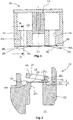
- FIG. 2 a sectional view through the outlet valve forward run 20 1 is shown.
- the forward outlet valve 20 1 is formed from the kidney-shaped leaf spring 40 1 , a valve seat 30 raised by the pump housing and the kidney-shaped valve opening 24 1 connecting the pump chamber 12 and the outlet chamber 14.
- the raised valve seat 30 formed with the elevation E projects beyond a region of the pump housing that is directly adjacent to the valve seat 30.
- the valve opening 24 1 is opened by the leaf spring 40 1 , as in FIG Figure 2 shown, locked.
- the leaf spring 40 1 lies against the valve seat 30 in a sealing manner with an overlap U.
- the leaf spring 40 1 In an open position, the leaf spring 40 1 is bent in such a way that it is spaced apart from the valve seat 30.
- the movement of the leaf spring 40 1 is limited by a valve limiter 45 provided at a distance from the valve seat 30 in the direction of movement of the leaf spring 40 1.
- a valve limiter 45 provided at a distance from the valve seat 30 in the direction of movement of the leaf spring 40 1.
- 51 is provided on an outer peripheral surface of the valve opening 24 1.
- the raised valve seat 30 is thus surrounded by two chamfers 50, 51.
- the leaf spring 40 1 is designed in such a way that it protrudes laterally beyond the valve seat 30.
- the leaf spring thus has a radial overhang UH.
- FIG. 3 shows a second embodiment of the present invention, in which two outlet valves 20 1 , 20 2 are provided.
- One outlet valve 20 1 forms a fluid outlet during a forward run and the other outlet valve 20 2 forms a fluid outlet during a reverse run of the rotor 11.
- the valve openings 24 1 , 24 2 of the outlet valves 20 1 , 20 2 are, in the outflow direction of the fluid, provided to the right and left of a fastening means 70.
- This fastening means 70 fixes a spring body 72, which forms the kidney-shaped leaf springs 40 1 , 40 2 and the one -piece valve limiter 45, which is arranged above the leaf springs 40 1, 40 2 in the outflow direction of the fluid, between the two kidney-shaped valve openings 24 1 , 24 2 on the Partition 22.
- the valve limiter 45 In the outflow direction of the fluid, the valve limiter 45 has kidney-shaped valve limiter openings 74 to the right and left of the fastening means 70, which are provided above the leaf springs 40 1 , 40 2 in the outflow direction of the fluid and which protrude laterally through the leaf springs 40 1 , 40 2 become.
- These valve limiter openings 74 enable the leaf springs 40 1 , 40 2 to be more easily released from the valve limiter 45 during a closing process.
Landscapes
- Engineering & Computer Science (AREA)
- Mechanical Engineering (AREA)
- General Engineering & Computer Science (AREA)
- Applications Or Details Of Rotary Compressors (AREA)
- Check Valves (AREA)
- Compressor (AREA)
Description
- Die vorliegende Erfindung betrifft eine Kfz-Vakuumpumpe mit einem Pumpraum, in dem ein Pumpenrotor verdichtend rotiert, und einem Auslassraum, in den das verdichtete Gas aus dem Pumpraum austritt. Die Vakuumpumpe weist eine Trennwand, welche den Pumpraum von dem Auslassraum abtrennt, und wenigstens ein als Rückschlagventil ausgebildetes Auslassventil in der Trennwand auf, durch das das komprimierte Gas aus dem Pumpraum in den Auslassraum austritt.
- Eine Kfz-Vakuumpumpe generiert in einem Kraftfahrzeug (Kfz) unabhängig von dem Betriebszustand eines Verbrennungsmotors einen Unterdruck von beispielsweise absolut 100 Millibar, der beispielsweise zum Betrieb eines pneumatischen Bremskraftverstärkers und/oder anderer pneumatisch betriebener Nebenaggregate benötigt wird.
- Als Ventilkörper für das Auslassventil wird bei einer solchen Vakuumpumpe aufgrund der einfachen Konstruktion und der hohen Zuverlässigkeit häufig eine Blattfeder verwendet, welche in einer Schließstellung an einem um die Auslassöffnung ausgebildeten Ventilsitz anliegt. Die Betätigung des Auslassventils erfolgt hydraulisch und pneumatisch. Problematisch bei solchen Vorgängen ist die dadurch entstehende Geräuschemission, welche hauptsächlich durch die Expansion des Öi/Luftgemisch verursacht wird. Weitere Geräuschemissionen entstehen durch den beim Schließen mit hohen Beschleunigungen ungebremsten Aufschlag des Ventilkörpers auf dem Ventilsitz.
- Aus der
EP 1 953 389 A2 ist eine Vakuumpumpe bekannt, bei welcher zur Geräuschreduktion in der Blattfeder des Auslassventils ein Loch vorgesehen ist, um die Druckdifferenz in diesem Bereich zu verringern. - Eine weitere Vakuumpumpe ist aus der
DE 102 27 772 A1 bekannt. Zur Geräuschreduktion ist bei dieser Vakuumpumpe in der Nähe der Ventilöffnung ein Kanal ausgebildet, welcher den Pumpraum mit dem Auslassraum verbindet, um die Öffnungs- und Schließbewegung der Blattfeder zu verlangsamen und die Druckdifferenz in diesem Bereich zu verringern. - Bei diesen Vakuumpumpen aus dem Stand der Technik besteht eine dauerhafte Verbindung zwischen dem Pumpraum und dem Auslassraum. Somit ist eine Dichtigkeit der Vakuumpumpe bei geschlossenem Auslassventil nicht gegeben. Daraus ergibt sich das Problem, dass durch diese Maßnahmen der Pumpraum belüftet wird, wodurch die Leistungsaufnahme der Pumpe signifikant verschlechtert wird.
- Aus
DE 10 2015 100 987 A1 ist eine Vakuumpumpe mit einem Auslassventil bekannt, bei der ein separates Bauteil einen erhabenen Ventilsitz definiert. - Aus
WO 2010/145633 A2 ist eine Vakuumpumpe bekannt, die zwei Auslassventile aufweist. - Die Aufgabe der vorliegenden Erfindung liegt somit darin, eine leise Kfz-Vakuumpumpe mit gutem Wirkungsgrad zu schaffen.
- Diese Aufgabe wird durch eine Kfz-Vakuumpumpe nach dem unabhängigen Anspruch 1 gelöst.
- Bei dieser Kfz-Vakuumpumpe ist der Ventilsitz, welcher um die Ventilöffnung herum vorgesehen ist, erhaben ausgebildet. Der Ventilsitz ist dabei der Teil des Gehäuses, welcher eine Auflagefläche für die Blattfeder die den Ventilkörper bildet, bildet. In geschlossenem Zustand liegt die Blattfeder dabei in einem vorgespannten Zustand dichtend an dem Ventilsitz an, so dass die Pumpe nicht belüftet wird. Dadurch wird der Wirkungsgrad der Pumpe verbessert. Als "erhaben" im Sinne der vorliegenden Erfindung ist eine Ausgestaltung zu verstehen, bei welcher der Bereich des Gehäuses, der den Ventilsitz ausbildet, sich von einem direkt daran angrenzenden Bereich um wenigstens 0,2 mm konstruktiv abhebt. Ein erhabener Ventilsitz hat den Vorteil, dass damit der Ventilsitz klar definiert von dem daran angrenzenden Gehäuse abgegrenzt ist. Bei einer ölgeschmierten Vakuumpumpe wird im Betrieb, zusammen mit dem Gas, Öl aus der Ventilöffnung ausgestoßen, das sich auch auf dem Ventilsitz und der Blattfeder absetzt. Dieses Öl generiert beim Öffnen eine erhebliche Adhäsionskraft zwischen dem Ventilsitz und der Blattfeder. Eine hohe Adhäsionskraft hat den Nachteil, dass die Blattfeder erst bei höheren Auslassdrücken öffnet. Durch höhere Auslassdrücke kommt es zu einer verstärkten Expansion des ÖI/Gas Gemisches am Ventilauslass, welches zu einer erhöhten Geräuschemission führt. Der erhabene Ventilsitz hat somit den Vorteil, dass sich eine Adhäsionskraft nur zwischen Ventilsitz und Blattfeder ausbildet und nicht noch zusätzlich zwischen der Blattfeder und den an den Ventilsitz angrenzenden Bereichen. Dadurch wird die Geräuschemission der Vakuumpumpe reduziert.
- Eine radiale Überlappung des Ventilsitzes und der Blattfeder nach der vorliegenden Erfindung beträgt dabei weniger als 1,5 mm, bevorzugt 1,0 mm und besonders bevorzugt jedoch weniger als 0,7 mm. Die Überlappung ist in einem überwiegenden Bereich, d.h. mehr als 50% des Umfangs des Ventilsitzes vorhanden. In einem Befestigungsbereich der Blattfeder, in welchem praktisch keine Öffnungsbewegung stattfindet, bzw. der Ölfilm zwischen Ventilsitz und Blattfeder nicht abreißt, kann die Blattfeder eine größere Überlappung aufweisen. Als Überlappung im Sinne der Erfindung wird der Bereich des Ventilsitzes verstanden, welcher in Kontakt mit der geschlossenen Blattfeder kommt. In diesem Kontaktbereich überlappt die Blattfeder mit dem Ventilsitz. Eine radiale Richtung im Sinne der vorliegenden Erfindung ist eine Richtung, die in der Ebene des Ventilsitzes, senkrecht zu einer Umfangsrichtung des Ventilsitzes verläuft. Durch eine Verringerung der Überlappung wird die Adhäsionskraft zwischen Blattfeder und Ventilsitz reduziert, so dass die Abströmung beim Öffnen harmonisiert wird. Durch die Verringerung der Überlappung öffnet die Blattfeder bereits bei geringeren Auslassdrücken. Dadurch wird eine von dem Auslassdruck abhängige Expansion des ausgelassenen ÖI/Gas Gemisches reduziert. Daraus folgt, dass auch die Geräuschemission reduziert wird, so dass die Vakuumpumpe im Betrieb zusätzlich leiser wird.
- Ein radialer Überhang der Blattfeder ist größer als 1,0 mm. Der Wert des radialen Überhangs ist jedoch nicht an jeder Stelle gleich und kann lokal auch unter 1,0 mm betragen. Im Sinne der Erfindung ist unter dem Wert für den radialen Überhang von 1,0 mm zu verstehen, dass ein Mittelwert für den radialen Überhang größer als 1,0 mm ist. Als radialer Überhang nach der vorliegenden Erfindung wird der Bereich der Blattfeder verstanden, der den Ventilsitz in radialer Richtung nach außen überragt. Durch diese Ausgestaltung kann sich zusätzlich ein Luftkissen zwischen Blattfeder und Gehäuse ausbilden. Dieses Luftkissen bremst die Blattfeder bei der Schließbewegung zusätzlich ab, so dass die Geräuschemission weiter verringert werden kann.
- Bisher mussten bei der Herstellung der Blattfeder und des Ventilsitzes und bei der Montage der Vakuumpumpe in der Regel enge Fehlertoleranzen eingehalten werden, damit die Blattfeder nach der Montage exakt auf dem Ventilsitz aufliegt. Durch Ausbildung eines Überhanges wird der Bereich, bei dem die Blattfeder in einem ungünstigen Fall den Ventilsitz noch abdeckt, vergrößert. Es ist somit möglich, die Blattfeder und den Ventilsitz mit weniger strengen Fehlertoleranzen herzustellen und zu montieren. Dadurch können die Blattfeder und der Ventilsitz wirtschaftlicher hergestellt werden und die Montage wird erleichtert.
- Die Erhabenheit des Ventilsitzes ist mindestens 0,5 mm, bevorzugt mindestens 1,0 mm und besonders bevorzugt mindestens 1,5. Als Erhabenheit im Sinne der Erfindung wird der Abstand zwischen dem Ventilsitz und einer Gehäuseoberfläche verstanden, von welcher der Ventilsitz sich konstruktiv abhebt. Dadurch ist es möglich am Umfang des Ventilsitzes eine ausreichende Fase vorzusehen.
- Die in der Vakuumpumpe eingesetzte Blattfeder hat vorzugsweise eine Dicke von 0,15 - 0,2 mm. Als Material wird für die Blattfeder vorzugsweise Uddeholm UHB Stainless 716 Stahl verwendet.
- Gemäß einer bevorzugten Ausgestaltung ist der Ventilsitz von wenigstens einer angrenzenden Fase umgeben. Als Fase im Sinne der Erfindung sind Radien, Kantenbrüche oder eine abgeschrägte Fläche zu verstehen, welche an einer Werkstückkante ausgebildet ist. Die Fase verbindet dabei zwei verschiedene Seiten eines Werkstückes.
- Die Fase hat die Wirkung, dass sich beim Schließvorgang der Blattfeder zwischen der Fase und der Blattfeder ein zirkuläres Luftpolster mit höherem Druck bildet, welches die Blattfeder abbremst und die Geräuschentwicklung zwischen Ventilsitz und Blattfeder minimiert. Das Geräusch, welches durch ein Anschlagen der Blattfeder an dem Ventilsitz entsteht, wird dadurch erheblich verringert.
- Vorzugsweise ist die Fase am inneren Umfang des erhabenen Ventilsitzes ausgebildet. Die Fase grenzt dabei innenseitig, also proximal an den Ventilsitz an. Eine solche Fase hat den Vorteil, dass hierfür keine Konstruktionsänderungen vorgenommen werden müssen. Die Fase kann somit auch noch nachträglich an dem erhabenen Ventilsitz ausgebildet werden. Anstelle der Fase am inneren Umfang oder zusätzlich dazu kann in einer weiteren bevorzugten Ausgestaltung eine Fase am äußeren Umfang des erhabenen Ventilsitzes ausgebildet werden.
- In einer bevorzugten Ausgestaltung der Erfindung sind die Ventilöffnung und die Blattfeder nierenförmig ausgebildet und die Blattfeder an einem Längsende fixiert. Dies hat den Vorteil, dass sich das Auslassventil platzsparend in ein Gehäuse unterbringen lässt.
- Vorzugsweise sind in einem weiteren Ausführungsbeispiel in der Trennwand zwei Auslassventile ausgebildet. Das erste Auslassventil bildet einen Fluid-Auslass während eines Vorwärtslaufes und das zweite Auslassventil einen Fluid-Auslass während eines Rückwärtslaufes des Rotors. Dies hat den Vorteil, dass die Kfz-Vakuumpumpe in beiden Laufrichtungen des Rotors betrieben werden kann. Die beiden Blattfedern der Auslassventile sind dabei durch einen einzigen gemeinsamen Federkörper gebildet. Dadurch wird die Anzahl an Teilen der Vakuumpumpe reduziert, so dass der Zusammenbau erleichtert wird und eine Verwechselung zwischen den Blattfedern ausgeschlossen wird.
- Weitere Einzelheiten und Vorteile der vorliegenden Erfindung ergeben sich aus der nachfolgenden Beschreibung der Ausführungsbeispiele in Verbindung mit den Zeichnungen. In diesen zeigen:
- Figur 1:
- Eine Kfz-Vakuumpumpe nach der vorliegenden Erfindung,
- Figur 2:
- Eine Schnittdarstellung des Auslassventils der Kfz-Vakuumpumpe nach
Fig. 1 - Figur 3:
- Eine Draufsicht des Auslassventils der Kfz-Vakuumpumpe nach
Fig. 1 gemäß einem zweiten Ausführungsbeispiel. -
Figur 1 zeigt eine Kfz-Vakuumpumpe 10 nach der vorliegenden Erfindung. Die Vakuumpumpe 10 bildet einen Pumpraum 12 aus, in welchem ein Gas durch einen rotierenden Pumpenrotor 11 verdichtet wird. Eine Trennwand 22 trennt den Pumpraum 12 von einem Auslassraum 14 ab. In der Trennwand 22 ist eine nierenförmige Ventilöffnung Vorwärtslauf 241 und eine nierenförmige Ventilöffnung Rückwärtslauf 242 ausgebildet. Zur fluidischen Verbindung des Pumpraums 12 und des Auslassraums 14 weist die Vakuumpumpe 10 ein als Rückschlagventil ausgebildetes Auslassventil Vorwärtslauf 201 und ein als Rückschlagventil ausgebildetes Auslassventil Rückwärtslauf 202 auf. Die Auslassventile 201, 202 weisen als Ventilkörper nierenförmige Blattfedern 401, 402 auf, die in einem geschlossenem Zustand die Ventilöffnungen 241, 242 verschließen. - In
Figur 2 ist eine Schnittdarstellung durch das Auslassventil Vorwärtslauf 201 gezeigt. Das Auslassventil Vorwärtslauf 201 ist gebildet aus der nierenförmigen Blattfeder 401, einem durch das Pumpengehäuse erhaben ausgebildeten Ventilsitz 30 und der den Pumpraum 12 und den Auslassraum 14 verbindenden nierenförmigen Ventilöffnung 241. Der mit der Erhabenheit E ausgebildete erhabene Ventilsitz 30 überragt einen direkt an den Ventilsitz 30 angrenzenden Bereich des Pumpengehäuses. Die Ventilöffnung 241 wird durch die Blattfeder 401, wie inFigur 2 dargestellt, verschlossen. In der Schließstellung liegt die Blattfeder 401 mit einer Überlappung U an dem Ventilsitz 30 dichtend an. In einer Öffnungsstellung ist die Blattfeder 401 derart gebogen, dass sie beabstandet zu dem Ventilsitz 30 ist. Die Bewegung der Blattfeder 401 wird dabei durch einen in Bewegungsrichtung der Blattfeder 401 zum Ventilsitz 30 beabstandet vorgesehenen Ventilbegrenzer 45 begrenzt. Um die Geräuschemission zu verringern ist an einer inneren Umfangsfläche und an einer äußeren Umfangsfläche der Ventilöffnung 241 jeweils eine Fase 50, 51 vorgesehen. In dem Ausführungsbeispiel nachFigur 2 ist der erhabene Ventilsitz 30 somit von zwei Fasen 50, 51 umgeben. Die Blattfeder 401 ist derart ausgebildet, dass sie den Ventilsitz 30 lateral überragt. Die Blattfeder weist damit einen radialen Überhang UH auf. Damit liegen die lateralen Enden der Blattfeder 401, in Ausflussrichtung des Fluides, oberhalb eines Bereiches des Pumpengehäuses, welcher an den erhabenen Ventilsitz 30 angrenzt, -
Figur 3 zeigt ein zweites Ausführungsbeispiel der vorliegenden Erfindung, bei welchem zwei Auslassventile 201, 202 vorgesehen sind. Ein Auslassventil 201 bildet einen Fluid-Auslass während eines Vorwärtslaufes und das andere Auslassventil 202 einen Fluid-Auslass während eines Rückwärtslaufes des Rotors 11. Die Ventilöffnungen 241, 242 der Auslassventile 201, 202 sind, in Ausflussrichtung des Fluides, rechts und links von einem Befestigungsmittel 70 vorgesehen. Dieses Befestigungsmittel 70 fixiert einen Federkörper 72, welcher die nierenförmige Blattfedern 401, 402 ausbildet und den, in Ausflussrichtung des Fluides, oberhalb der Blattfedern 401, 402 angeordneten einstückigen Ventilbegrenzer 45 zwischen den beiden nierenförmigen Ventilöffnungen 241, 242 an der Trennwand 22. In Ausflussrichtung des Fluides weist der Ventilbegrenzer 45 rechts und links von dem Befestigungsmittel 70 nierenförmige Ventilbegrenzeröffnungen 74 auf, welche in Ausflussrichtung des Fluides oberhalb der Blattfedern 401, 402 vorgesehen sind und die lateral durch die Blattfedern 401, 402 überragt werden. Diese Ventilbegrenzeröffnungen 74 ermöglichen ein leichteres Lösen der Blattfedern 401, 402 von dem Ventilbegrenzer 45 bei einem Schließvorgang. -
- 10
- Kfz-Vakuumpumpe
- 11
- Pumpenrotor
- 12
- Pumpraum
- 14
- Auslassraum
- 201
- Auslassventil Vorwärtslauf
- 202
- Auslassventil Rückwärtslauf
- 22
- Trennwand
- 241
- Ventilöffnung Vorwärtslauf
- 242
- Ventilöffnung Rückwärtslauf
- 30
- Ventilsitz
- 401
- Blattfeder Vorwärtslauf
- 402
- Blattfeder Rückwärtslauf
- 45
- Ventilbegrenzer
- 50, 51
- Fase
- 70
- Befestigungsmittel
- 72
- Federkörper
- 74
- Ventilbegrenzeröffnung
- E
- Erhabenheit
- U
- Überlappung
- UH
- Überhang
Claims (6)
- Kfz-Vakuumpumpe (10), die ölgeschmiert ist, umfassend:einen Pumpraum (12), in dem ein Pumpenrotor (11) verdichtend rotiert,einen Auslassraum (14), in den das verdichtete Gas aus dem Pumpraum (12) austritt,eine Trennwand (22), die den Pumpraum (12) von dem Auslassraum (14) trennt, undwenigstens ein als Rückschlagventil ausgebildetes Auslassventil (201, 202) in der Trennwand (22), durch das das komprimierte Gas aus dem Pumpraum (12) in den Auslassraum (14) austritt,wobei das Auslassventil (201, 202) von einer Ventilöffnung (241, 242) in der Trennwand (22), einem Ventilsitz (30), welcher um die Ventilöffnung (241, 242) herum vorgesehen ist, und einer Blattfeder (401, 402) als Ventilkörper gebildet ist, wobeidie Blattfeder (401, 402) zwischen einer geschlossenen Stellung des Auslassventils (201, 202), in welcher die Blattfeder (401, 402) auf dem Ventilsitz (30) aufliegt, und einer geöffneten Stellung des Auslassventils (201, 202), in welcher die Blattfeder (401, 402) zu dem Ventilsitz (30) beabstandet ist, bewegbar ist,der Ventilsitz (30) erhaben ausgebildet ist, dadurch gekennzeichnet, dass die radiale Überlappung (U) des Ventilsitzes (30) und der Blattfeder (401, 402) weniger als 1,5 mm beträgt,der radiale Überhang (UH) der Blattfeder (401, 402) größer als 1,0 mm ist, unddie Erhabenheit (E) des Ventilsitzes (30) mindestens 0,5 mm, bevorzugt mindestens 1,0 mm ist.
- Kfz-Vakuumpumpe (10) nach Anspruch 1, dadurch gekennzeichnet, dass der Ventilsitz (30) von wenigstens einer angrenzenden Fase (50, 51) umgeben ist.
- Kfz-Vakuumpumpe (10) nach Anspruch 2, dadurch gekennzeichnet, dass die Fase (50) am inneren Umfang des erhabenen Ventilsitzes (30) ausgebildet ist.
- Kfz-Vakuumpumpe (10) nach Anspruch 2 oder 3, dadurch gekennzeichnet, dass die Fase (51) am äußeren Umfang des erhabenen Ventilsitzes (30) ausgebildet ist.
- Kfz-Vakuumpumpe (10) nach einem der vorherigen Ansprüche, dadurch gekennzeichnet, dass die Ventilöffnung (241, 242) und die Blattfeder (401, 402) nierenförmig ausgebildet sind und die Blattfeder (401, 402) an einem Längsende fixiert ist,
- Kfz-Vakuumpumpe (10) nach einem der vorherigen Ansprüche, dadurch gekennzeichnet, dass in der Trennwand (22) zwei Auslassventile (201, 202) ausgebildet sind, wobei die beiden Blattfedern (401, 402) der Auslassventile (201, 202) durch einen einzigen gemeinsamen Federkörper (72) gebildet sind.
Applications Claiming Priority (1)
| Application Number | Priority Date | Filing Date | Title |
|---|---|---|---|
| PCT/EP2015/071848 WO2017050362A1 (de) | 2015-09-23 | 2015-09-23 | Kfz-vakuumpumpe |
Publications (2)
| Publication Number | Publication Date |
|---|---|
| EP3353423A1 EP3353423A1 (de) | 2018-08-01 |
| EP3353423B1 true EP3353423B1 (de) | 2021-08-04 |
Family
ID=54150441
Family Applications (1)
| Application Number | Title | Priority Date | Filing Date |
|---|---|---|---|
| EP15766870.8A Active EP3353423B1 (de) | 2015-09-23 | 2015-09-23 | Kfz-vakuumpumpe |
Country Status (5)
| Country | Link |
|---|---|
| US (1) | US20180291906A1 (de) |
| EP (1) | EP3353423B1 (de) |
| JP (1) | JP2018523780A (de) |
| CN (1) | CN108026926A (de) |
| WO (1) | WO2017050362A1 (de) |
Family Cites Families (8)
| Publication number | Priority date | Publication date | Assignee | Title |
|---|---|---|---|---|
| JPS5343508U (de) * | 1976-09-20 | 1978-04-14 | ||
| JPS55100757U (de) * | 1978-12-29 | 1980-07-14 | ||
| BR8901183A (pt) * | 1989-03-09 | 1990-10-16 | Brasil Compressores Sa | Valvula de descarga para compressor rotativo de pistao rolante |
| JPH0717985U (ja) * | 1993-09-08 | 1995-03-31 | 日本真空技術株式会社 | 油回転真空ポンプ |
| JP2009293546A (ja) * | 2008-06-06 | 2009-12-17 | Hitachi Appliances Inc | 密閉形圧縮機、およびこれを用いた冷蔵庫又はルームエアコン |
| WO2010145633A2 (de) * | 2009-06-17 | 2010-12-23 | Ixetic Hückeswagen Gmbh | Vakuumpumpe |
| DE102010044898A1 (de) * | 2010-09-09 | 2012-03-15 | Schwäbische Hüttenwerke Automotive GmbH | Vakuumpumpe mit Lüftungseinrichtung |
| JP2015140709A (ja) * | 2014-01-28 | 2015-08-03 | トヨタ自動車株式会社 | ベーン式バキュームポンプ |
-
2015
- 2015-09-23 JP JP2018508202A patent/JP2018523780A/ja active Pending
- 2015-09-23 WO PCT/EP2015/071848 patent/WO2017050362A1/de not_active Ceased
- 2015-09-23 EP EP15766870.8A patent/EP3353423B1/de active Active
- 2015-09-23 US US15/761,814 patent/US20180291906A1/en not_active Abandoned
- 2015-09-23 CN CN201580083001.XA patent/CN108026926A/zh active Pending
Also Published As
| Publication number | Publication date |
|---|---|
| US20180291906A1 (en) | 2018-10-11 |
| WO2017050362A1 (de) | 2017-03-30 |
| JP2018523780A (ja) | 2018-08-23 |
| EP3353423A1 (de) | 2018-08-01 |
| CN108026926A (zh) | 2018-05-11 |
Similar Documents
| Publication | Publication Date | Title |
|---|---|---|
| DE102017110913B3 (de) | Verdrängermaschine nach dem Spiralprinzip, Verfahren zum Betreiben einer Verdrängermaschine, Fahrzeugklimaanlage und Fahrzeug | |
| DE102017105175B3 (de) | Verdrängermaschine nach dem Spiralprinzip, Verfahren zum Betreiben einer Verdrängermaschine, Verdrängerspirale, Fahrzeugklimaanlage und Fahrzeug | |
| WO2011045171A2 (de) | Doppel-innenzahnradpumpe | |
| DE102015106610A1 (de) | Pumpenvorrichtung | |
| EP2212167B1 (de) | Hydraulische kolbenpumpe | |
| DE102019107480B4 (de) | Entlüftete lippendichtung | |
| DE102019132729A1 (de) | Sickendichtung | |
| EP3356678B1 (de) | Mehrstufige drehschieberpumpe | |
| EP1774177A1 (de) | Kolbenpumpe mit verbessertem wirkungsgrad | |
| EP2815129A1 (de) | Dichtungsanordnung und pumpe mit einer dichtungsanordnung | |
| EP3371457B1 (de) | Kfz-vakuumpumpe | |
| DE102011087103A1 (de) | Geberzylinder | |
| DE2852852B1 (de) | Kolbenpumpe,insbesondere Radialkolbenpumpe | |
| DE102009002530A1 (de) | Hochdruckpumpe für ein Kraftstoffeinspritzsystem | |
| DE102010062174A1 (de) | Ventil, insbesondere ein Auslassventil einer hydraulischen Kolbenpumpe | |
| EP2908011B1 (de) | Kraftfahrzeug-Vakuumpumpe | |
| WO2017050362A1 (de) | Kfz-vakuumpumpe | |
| DE3801306A1 (de) | Fluegelzellenverdichter | |
| EP2574792B1 (de) | Flügelzellenpumpe | |
| EP3227560B1 (de) | Verdichter mit einem dichtkanal | |
| EP2238349B1 (de) | Kolbenkompressor mit einer ein lamellenventil aufweisenden ventilplatte | |
| EP3668727B1 (de) | Reifenventil | |
| WO2016188737A1 (de) | Pneumatischer bremskraftverstärker | |
| EP3470624A1 (de) | Rotationspumpe | |
| DE102015209304A1 (de) | Hydraulischer Nockenwellenversteller mit im Querschnitt trapezartigem Kurzschluss-Hydraulikmittelleitkanal-Rückschlagventil |
Legal Events
| Date | Code | Title | Description |
|---|---|---|---|
| STAA | Information on the status of an ep patent application or granted ep patent |
Free format text: STATUS: THE INTERNATIONAL PUBLICATION HAS BEEN MADE |
|
| PUAI | Public reference made under article 153(3) epc to a published international application that has entered the european phase |
Free format text: ORIGINAL CODE: 0009012 |
|
| STAA | Information on the status of an ep patent application or granted ep patent |
Free format text: STATUS: REQUEST FOR EXAMINATION WAS MADE |
|
| 17P | Request for examination filed |
Effective date: 20180220 |
|
| AK | Designated contracting states |
Kind code of ref document: A1 Designated state(s): AL AT BE BG CH CY CZ DE DK EE ES FI FR GB GR HR HU IE IS IT LI LT LU LV MC MK MT NL NO PL PT RO RS SE SI SK SM TR |
|
| AX | Request for extension of the european patent |
Extension state: BA ME |
|
| DAV | Request for validation of the european patent (deleted) | ||
| DAX | Request for extension of the european patent (deleted) | ||
| GRAP | Despatch of communication of intention to grant a patent |
Free format text: ORIGINAL CODE: EPIDOSNIGR1 |
|
| STAA | Information on the status of an ep patent application or granted ep patent |
Free format text: STATUS: GRANT OF PATENT IS INTENDED |
|
| INTG | Intention to grant announced |
Effective date: 20210225 |
|
| GRAS | Grant fee paid |
Free format text: ORIGINAL CODE: EPIDOSNIGR3 |
|
| GRAA | (expected) grant |
Free format text: ORIGINAL CODE: 0009210 |
|
| STAA | Information on the status of an ep patent application or granted ep patent |
Free format text: STATUS: THE PATENT HAS BEEN GRANTED |
|
| AK | Designated contracting states |
Kind code of ref document: B1 Designated state(s): AL AT BE BG CH CY CZ DE DK EE ES FI FR GB GR HR HU IE IS IT LI LT LU LV MC MK MT NL NO PL PT RO RS SE SI SK SM TR |
|
| REG | Reference to a national code |
Ref country code: GB Ref legal event code: FG4D Free format text: NOT ENGLISH |
|
| REG | Reference to a national code |
Ref country code: AT Ref legal event code: REF Ref document number: 1417243 Country of ref document: AT Kind code of ref document: T Effective date: 20210815 |
|
| REG | Reference to a national code |
Ref country code: CH Ref legal event code: EP |
|
| REG | Reference to a national code |
Ref country code: DE Ref legal event code: R096 Ref document number: 502015015031 Country of ref document: DE |
|
| REG | Reference to a national code |
Ref country code: IE Ref legal event code: FG4D Free format text: LANGUAGE OF EP DOCUMENT: GERMAN |
|
| REG | Reference to a national code |
Ref country code: LT Ref legal event code: MG9D |
|
| REG | Reference to a national code |
Ref country code: NL Ref legal event code: MP Effective date: 20210804 |
|
| PG25 | Lapsed in a contracting state [announced via postgrant information from national office to epo] |
Ref country code: HR Free format text: LAPSE BECAUSE OF FAILURE TO SUBMIT A TRANSLATION OF THE DESCRIPTION OR TO PAY THE FEE WITHIN THE PRESCRIBED TIME-LIMIT Effective date: 20210804 Ref country code: SE Free format text: LAPSE BECAUSE OF FAILURE TO SUBMIT A TRANSLATION OF THE DESCRIPTION OR TO PAY THE FEE WITHIN THE PRESCRIBED TIME-LIMIT Effective date: 20210804 Ref country code: RS Free format text: LAPSE BECAUSE OF FAILURE TO SUBMIT A TRANSLATION OF THE DESCRIPTION OR TO PAY THE FEE WITHIN THE PRESCRIBED TIME-LIMIT Effective date: 20210804 Ref country code: PT Free format text: LAPSE BECAUSE OF FAILURE TO SUBMIT A TRANSLATION OF THE DESCRIPTION OR TO PAY THE FEE WITHIN THE PRESCRIBED TIME-LIMIT Effective date: 20211206 Ref country code: NO Free format text: LAPSE BECAUSE OF FAILURE TO SUBMIT A TRANSLATION OF THE DESCRIPTION OR TO PAY THE FEE WITHIN THE PRESCRIBED TIME-LIMIT Effective date: 20211104 Ref country code: FI Free format text: LAPSE BECAUSE OF FAILURE TO SUBMIT A TRANSLATION OF THE DESCRIPTION OR TO PAY THE FEE WITHIN THE PRESCRIBED TIME-LIMIT Effective date: 20210804 Ref country code: ES Free format text: LAPSE BECAUSE OF FAILURE TO SUBMIT A TRANSLATION OF THE DESCRIPTION OR TO PAY THE FEE WITHIN THE PRESCRIBED TIME-LIMIT Effective date: 20210804 Ref country code: LT Free format text: LAPSE BECAUSE OF FAILURE TO SUBMIT A TRANSLATION OF THE DESCRIPTION OR TO PAY THE FEE WITHIN THE PRESCRIBED TIME-LIMIT Effective date: 20210804 Ref country code: BG Free format text: LAPSE BECAUSE OF FAILURE TO SUBMIT A TRANSLATION OF THE DESCRIPTION OR TO PAY THE FEE WITHIN THE PRESCRIBED TIME-LIMIT Effective date: 20211104 |
|
| PG25 | Lapsed in a contracting state [announced via postgrant information from national office to epo] |
Ref country code: PL Free format text: LAPSE BECAUSE OF FAILURE TO SUBMIT A TRANSLATION OF THE DESCRIPTION OR TO PAY THE FEE WITHIN THE PRESCRIBED TIME-LIMIT Effective date: 20210804 Ref country code: LV Free format text: LAPSE BECAUSE OF FAILURE TO SUBMIT A TRANSLATION OF THE DESCRIPTION OR TO PAY THE FEE WITHIN THE PRESCRIBED TIME-LIMIT Effective date: 20210804 Ref country code: GR Free format text: LAPSE BECAUSE OF FAILURE TO SUBMIT A TRANSLATION OF THE DESCRIPTION OR TO PAY THE FEE WITHIN THE PRESCRIBED TIME-LIMIT Effective date: 20211105 |
|
| PG25 | Lapsed in a contracting state [announced via postgrant information from national office to epo] |
Ref country code: NL Free format text: LAPSE BECAUSE OF FAILURE TO SUBMIT A TRANSLATION OF THE DESCRIPTION OR TO PAY THE FEE WITHIN THE PRESCRIBED TIME-LIMIT Effective date: 20210804 |
|
| PG25 | Lapsed in a contracting state [announced via postgrant information from national office to epo] |
Ref country code: DK Free format text: LAPSE BECAUSE OF FAILURE TO SUBMIT A TRANSLATION OF THE DESCRIPTION OR TO PAY THE FEE WITHIN THE PRESCRIBED TIME-LIMIT Effective date: 20210804 |
|
| REG | Reference to a national code |
Ref country code: CH Ref legal event code: PL |
|
| REG | Reference to a national code |
Ref country code: DE Ref legal event code: R097 Ref document number: 502015015031 Country of ref document: DE |
|
| REG | Reference to a national code |
Ref country code: BE Ref legal event code: MM Effective date: 20210930 |
|
| PG25 | Lapsed in a contracting state [announced via postgrant information from national office to epo] |
Ref country code: SM Free format text: LAPSE BECAUSE OF FAILURE TO SUBMIT A TRANSLATION OF THE DESCRIPTION OR TO PAY THE FEE WITHIN THE PRESCRIBED TIME-LIMIT Effective date: 20210804 Ref country code: SK Free format text: LAPSE BECAUSE OF FAILURE TO SUBMIT A TRANSLATION OF THE DESCRIPTION OR TO PAY THE FEE WITHIN THE PRESCRIBED TIME-LIMIT Effective date: 20210804 Ref country code: RO Free format text: LAPSE BECAUSE OF FAILURE TO SUBMIT A TRANSLATION OF THE DESCRIPTION OR TO PAY THE FEE WITHIN THE PRESCRIBED TIME-LIMIT Effective date: 20210804 Ref country code: MC Free format text: LAPSE BECAUSE OF FAILURE TO SUBMIT A TRANSLATION OF THE DESCRIPTION OR TO PAY THE FEE WITHIN THE PRESCRIBED TIME-LIMIT Effective date: 20210804 Ref country code: EE Free format text: LAPSE BECAUSE OF FAILURE TO SUBMIT A TRANSLATION OF THE DESCRIPTION OR TO PAY THE FEE WITHIN THE PRESCRIBED TIME-LIMIT Effective date: 20210804 Ref country code: CZ Free format text: LAPSE BECAUSE OF FAILURE TO SUBMIT A TRANSLATION OF THE DESCRIPTION OR TO PAY THE FEE WITHIN THE PRESCRIBED TIME-LIMIT Effective date: 20210804 Ref country code: AL Free format text: LAPSE BECAUSE OF FAILURE TO SUBMIT A TRANSLATION OF THE DESCRIPTION OR TO PAY THE FEE WITHIN THE PRESCRIBED TIME-LIMIT Effective date: 20210804 |
|
| PLBE | No opposition filed within time limit |
Free format text: ORIGINAL CODE: 0009261 |
|
| STAA | Information on the status of an ep patent application or granted ep patent |
Free format text: STATUS: NO OPPOSITION FILED WITHIN TIME LIMIT |
|
| 26N | No opposition filed |
Effective date: 20220506 |
|
| GBPC | Gb: european patent ceased through non-payment of renewal fee |
Effective date: 20211104 |
|
| PG25 | Lapsed in a contracting state [announced via postgrant information from national office to epo] |
Ref country code: LU Free format text: LAPSE BECAUSE OF NON-PAYMENT OF DUE FEES Effective date: 20210923 Ref country code: IT Free format text: LAPSE BECAUSE OF FAILURE TO SUBMIT A TRANSLATION OF THE DESCRIPTION OR TO PAY THE FEE WITHIN THE PRESCRIBED TIME-LIMIT Effective date: 20210804 Ref country code: IE Free format text: LAPSE BECAUSE OF NON-PAYMENT OF DUE FEES Effective date: 20210923 Ref country code: BE Free format text: LAPSE BECAUSE OF NON-PAYMENT OF DUE FEES Effective date: 20210930 |
|
| PG25 | Lapsed in a contracting state [announced via postgrant information from national office to epo] |
Ref country code: SI Free format text: LAPSE BECAUSE OF FAILURE TO SUBMIT A TRANSLATION OF THE DESCRIPTION OR TO PAY THE FEE WITHIN THE PRESCRIBED TIME-LIMIT Effective date: 20210804 Ref country code: LI Free format text: LAPSE BECAUSE OF NON-PAYMENT OF DUE FEES Effective date: 20210930 Ref country code: CH Free format text: LAPSE BECAUSE OF NON-PAYMENT OF DUE FEES Effective date: 20210930 |
|
| PG25 | Lapsed in a contracting state [announced via postgrant information from national office to epo] |
Ref country code: FR Free format text: LAPSE BECAUSE OF NON-PAYMENT OF DUE FEES Effective date: 20211004 |
|
| PG25 | Lapsed in a contracting state [announced via postgrant information from national office to epo] |
Ref country code: GB Free format text: LAPSE BECAUSE OF NON-PAYMENT OF DUE FEES Effective date: 20211104 |
|
| REG | Reference to a national code |
Ref country code: AT Ref legal event code: MM01 Ref document number: 1417243 Country of ref document: AT Kind code of ref document: T Effective date: 20210923 |
|
| PG25 | Lapsed in a contracting state [announced via postgrant information from national office to epo] |
Ref country code: AT Free format text: LAPSE BECAUSE OF NON-PAYMENT OF DUE FEES Effective date: 20210923 |
|
| PG25 | Lapsed in a contracting state [announced via postgrant information from national office to epo] |
Ref country code: HU Free format text: LAPSE BECAUSE OF FAILURE TO SUBMIT A TRANSLATION OF THE DESCRIPTION OR TO PAY THE FEE WITHIN THE PRESCRIBED TIME-LIMIT; INVALID AB INITIO Effective date: 20150923 |
|
| PG25 | Lapsed in a contracting state [announced via postgrant information from national office to epo] |
Ref country code: CY Free format text: LAPSE BECAUSE OF FAILURE TO SUBMIT A TRANSLATION OF THE DESCRIPTION OR TO PAY THE FEE WITHIN THE PRESCRIBED TIME-LIMIT Effective date: 20210804 |
|
| PG25 | Lapsed in a contracting state [announced via postgrant information from national office to epo] |
Ref country code: MK Free format text: LAPSE BECAUSE OF FAILURE TO SUBMIT A TRANSLATION OF THE DESCRIPTION OR TO PAY THE FEE WITHIN THE PRESCRIBED TIME-LIMIT Effective date: 20210804 |
|
| PG25 | Lapsed in a contracting state [announced via postgrant information from national office to epo] |
Ref country code: MT Free format text: LAPSE BECAUSE OF FAILURE TO SUBMIT A TRANSLATION OF THE DESCRIPTION OR TO PAY THE FEE WITHIN THE PRESCRIBED TIME-LIMIT Effective date: 20210804 |
|
| PGFP | Annual fee paid to national office [announced via postgrant information from national office to epo] |
Ref country code: DE Payment date: 20250919 Year of fee payment: 11 |
|
| PG25 | Lapsed in a contracting state [announced via postgrant information from national office to epo] |
Ref country code: TR Free format text: LAPSE BECAUSE OF FAILURE TO SUBMIT A TRANSLATION OF THE DESCRIPTION OR TO PAY THE FEE WITHIN THE PRESCRIBED TIME-LIMIT Effective date: 20210804 |
|
| REG | Reference to a national code |
Ref country code: DE Ref legal event code: R082 Ref document number: 502015015031 Country of ref document: DE |