EP3350815B1 - Elektrozaunisolator - Google Patents
Elektrozaunisolator Download PDFInfo
- Publication number
- EP3350815B1 EP3350815B1 EP16846940.1A EP16846940A EP3350815B1 EP 3350815 B1 EP3350815 B1 EP 3350815B1 EP 16846940 A EP16846940 A EP 16846940A EP 3350815 B1 EP3350815 B1 EP 3350815B1
- Authority
- EP
- European Patent Office
- Prior art keywords
- passage
- insulator
- open end
- fence
- attachment portion
- Prior art date
- Legal status (The legal status is an assumption and is not a legal conclusion. Google has not performed a legal analysis and makes no representation as to the accuracy of the status listed.)
- Active
Links
Images

Classifications
-
- H—ELECTRICITY
- H01—ELECTRIC ELEMENTS
- H01B—CABLES; CONDUCTORS; INSULATORS; SELECTION OF MATERIALS FOR THEIR CONDUCTIVE, INSULATING OR DIELECTRIC PROPERTIES
- H01B17/00—Insulators or insulating bodies characterised by their form
- H01B17/14—Supporting insulators
- H01B17/145—Insulators, poles, handles, or the like in electric fences
-
- E—FIXED CONSTRUCTIONS
- E04—BUILDING
- E04H—BUILDINGS OR LIKE STRUCTURES FOR PARTICULAR PURPOSES; SWIMMING OR SPLASH BATHS OR POOLS; MASTS; FENCING; TENTS OR CANOPIES, IN GENERAL
- E04H17/00—Fencing, e.g. fences, enclosures, corrals
- E04H17/017—Fencing provided with electric elements or components, e.g. fencing member or component, such as fence strands, post, panel or rail, provided with electric elements or components
-
- E—FIXED CONSTRUCTIONS
- E04—BUILDING
- E04H—BUILDINGS OR LIKE STRUCTURES FOR PARTICULAR PURPOSES; SWIMMING OR SPLASH BATHS OR POOLS; MASTS; FENCING; TENTS OR CANOPIES, IN GENERAL
- E04H17/00—Fencing, e.g. fences, enclosures, corrals
- E04H17/02—Wire fencing, e.g. made of wire mesh
- E04H17/10—Wire fencing, e.g. made of wire mesh characterised by the way of connecting wire to posts; Droppers
- E04H17/124—Wire fencing, e.g. made of wire mesh characterised by the way of connecting wire to posts; Droppers connecting by one or more clamps, clips, screws, wedges or ties
Definitions
- the present invention relates to an insulator for an electric fence.
- Electric fencing is well known for use in applications such as security and is used to deliver an electric shock to objects that come in contact with the fencing, or to trigger an alarm if an intrusion attempt is detected.
- electric fences typically include a plurality of posts, with one or more fence lines of fencing wire passing along the posts to create a barrier.
- This wire is secured to end posts using brackets and tensioners to keep the fence lines taut, with insulators positioned on posts between the ends to keep the wires spaced apart from each other. Such insulators are required to prevent short circuiting of the wire through the post.
- the fence line may have variable orientation. This could be to accommodate changes in elevation of the terrain, avoid proximity to objects such as trees or structures which could compromise security, or simply follow a desired layout of the fence.
- the fence may produce external corners (i.e. the fence line passes around the fence post, at least in part) and internal corners (i.e. the fence line forms an oblique angle with the fence post at the vertex) along its length, in addition to changes in elevation.
- insulator designs attempt to accommodate for change in orientation along the fence line by using moving parts - for example suspended pulleys at corners.
- Such insulators create complexities in the manufacture and assembly of the insulators, as well as introducing potential points of failure into the design.
- the insulators can present a potential point of attack in terms of providing hand or foot holds for a would-be intruder when attempting to scale the fence without coming in contact with the fence wire or posts. It may be advantageous to provide an insulator and fence system which increases the likelihood of contact with shock carrying or alarm triggering elements of the fence - particularly within the vertical space between insulators.
- United States Patent No. 2858106 discloses an auxiliary device for temporarily supporting lines and the like in approximate positions of desired mounting on support members therefor.
- the auxiliary device has an elongated tubular member having opposite endwardly disposed rims and a slot longitudinally extended between the rims in a plane radially of the tubular member permitting passage of a line therethrough. Pairs of legs are rigidly secured to the rims and radially outwardly extended from the tubular member substantially normal to the plane of the slot.
- a guiding element extends outwardly from the tubular member adjacent to the slot having a front edge facing in the direction of the slot and a rear edge facing in a direction away from the slot adapted to guide a line removed from the tubular member along the front edge into a position releasably held against the rear edge of the guiding element.
- French Patent Application Publication No. 1222403A discloses an isolator for electric fences, intended to be fixed to the top of a stake and to carry an electric wire.
- the insulator comprises a duct whose axis is perpendicular to the axis of the stake, this duct serving on the one hand to provide a passage for the electrical wire and on the other hand to retain an electrically conductive member in front of the stake to protect it against the animals.
- German Patent Application Publication No. 957956C discloses an insulator having a tubular sleeve of rigid abrasion resistant material which serves as a bearing and guide for a fence line, with conically flared insulating tube pieces extending from either end of the tubular sleeve.
- a clamping ring is rigidly connected to a fixing screw for securing the insulator to a fence post.
- United States Patent No. 2438419 discloses an insulator comprising a block of insulating material having an opening therein through which a wire may pass and formed with a slot in one side communicating with the opening.
- a wire extends around the block with its end projecting beyond one side of the block and terminating in hooks bent at right angles to the wire ends to lie parallel to the adjacent block surface and facing in the same direction.
- the present invention provides for an insulator for an electric fence having at least one wire, according to independent claim 1.
- the insulator includes a body having a first end and a second end.
- the insulator includes a wire attachment portion positioned at the first end of the body.
- the insulator includes a passage passing through the wire attachment portion.
- the passage includes a first open end, a second open end, and a waist region between the first open end and the second open end. The diameter of the passage at the first open end and the diameter of the second open end are both greater than at the waist region.
- the insulator being for use with wire in an electric fence, it should be appreciated that it is also suitable for use with other filamentous barrier members known in the art - such as fibrous rope-like material woven with fine conducting wires (known as 'poly-wire').
- fence posts fence support structures
- Reference to the body of the insulator should be understood to mean a structural member for separating the wire attachment portion from the fence post.
- the body may be used to help define the desired distance between the fence post and the wire or line to be held by the insulator.
- the body may include a breakaway portion, configured to result in detachment of at least the wire attachment portion when subjected to a predetermined level of force.
- the breakaway portion may be a cutaway section as known in the art - for example as described in United States Patent No. 6290190 - unable to support at least a part of the weight of a potential intruder.
- the insulator includes a post connector portion at the second end of the body, for connecting the insulator to a support structure of the fence such as a fence post.
- the post connector portion may include opposing arms with a space therebetween.
- the connector portion may receive at least a portion of the post in the space between the arms.
- the arms may include fastener apertures, enabling a fastener to be passed through the apertures in the arms and corresponding apertures in the fence post to secure the insulator relative to the post.
- the post connector portion may be another suitable means known to a person skilled in the art for securing an electric fence insulator to a support structure.
- the wire attachment portion is made of any electrically insulating material deemed to be suitable by a person skilled in the art.
- the insulating material may be high density polyethylene (HDPE) - being electrically insulating while having material properties suitable for use in security fencing applications in terms of toughness. It should be appreciated that this is not intended to be limiting, and other exemplary materials may include nylon, polycarbonate, polyester, polypropylene, or acrylonitrile butadiene styrene (ABS).
- the insulator as a whole is manufactured as a unitary part.
- the cross section of the passage may be substantially circular in shape along its length. It is envisaged that this configuration may assist with enabling entry and exit of a wire to and from the passage in a range of orientations without bearing against edges along its length. It should be appreciated that this is not intended to be limiting, and that the passage may have other cross sectional shapes suitable for its intended purpose.
- the cross section may be elliptical, or a polygon. Further, the shape of the cross section may vary along the length of the passage.
- Reference to the diameter of the passage should be understood to mean the largest distance across the passage taken along an axis substantially orthogonal to a longitudinal axis between the first and second open ends of the passage. It should be appreciated that reference to diameter is not intended to be limited to the width of a circular shape - for example, in exemplary embodiments in which the cross section of the passage is polygonal, the diameter may be the length of the longest polygon diagonal (i.e., straight line segment joining two vertices).
- the configuration of the greater diameter of the passage at the first open end and the second open end than at the waist region may assist in accommodating for entry and exit of the wire to and from the passage in a range of directions, while reducing the likelihood of the wire producing a sharp angle or tight radius of curvature. This may reduce the likelihood of the integrity of the wire being compromised at that point (whether under sudden loading, or due to degradation of the wire over time), and make it easier for the wire to be pulled through the passage during installation.
- the passage flares outwardly from the waist region to the first open end and the second open end.
- Reference to the passage flaring should be understood to mean a gradual widening of the passage from the waist region along its length towards the first open end and the second open end. It is envisaged that this gradual widening may assist in reducing the likelihood of the wire bearing against a single point or edge of the passage.
- the flare is a curved flare.
- Reference to a curved flare should be understood to mean a non-linear widening of the passage such that the passage curves outwardly along its length towards the ends - with the change in width of the passage increasing towards each open end from the waist region.
- the passage may be substantially in the shape of a hyperboloid.
- the passage may be a circular hyperboloid, i.e., a hyperboloid in which each cross section of the passage is substantially circular. It is envisaged that this may assist in maintaining a minimum radius of curvature regardless of the incoming or exiting angle of the line. This may assist in reducing the likelihood of damage to the line caused by its bearing against an edge of the insulator. This may also assist in increasing the creepage distance from the wire to the post - the creepage being at a minimum when the wire angle is such that it contacts the passage at the widest part.
- the passage may have other cross sectional shapes suitable for its intended purpose, while still approximating a hyperboloid.
- the diameter of the first open end and the second open end, and the length of the passage between the first open end and the second open end may be selected to achieve sufficient creepage distance while also permitting a wide angle exit from the passage without kinking of the wire (i.e. without bearing against an edge of the open ends between the passage and outer surface of the wire attachment portion).
- the diameter of the first open end and the second open end may be in the order of about 40 mm to 50 mm. In an exemplary embodiment the diameter may be less than about 45 mm.
- the length of the passage between the first open end and the second open end may be in the order of about 40 mm to 50 mm. In an example, the length may be at least about 44 mm. It is envisaged that this may assist in enabling the use of the insulator to produce external corners in the fence while maintaining a suitable air gap between the wire and fence post to which the insulator is secured. Further, this may assist in avoiding the creation of sharp angles in the line entering and existing the passage.
- the diameter of the passage at its waist may be at least that of the wire intended for use with the insulator.
- clearance may be provided - for example the waist may have a diameter of about 7 mm to accommodate a 2.5 mm diameter wire.
- the wire attachment portion includes a wall having an interior surface defining the passage, and an exterior surface.
- At least a portion of the exterior surface of the wall between the passage and the body of the insulator is shaped to approximate the shape of the interior surface of the wall.
- the thickness of at least a portion of the exterior surface of the wall between the passage and the body of the insulator may be less than about 3 mm. In an example, the thickness may be less than about 1 mm. It is envisaged that the likelihood of short circuits or high voltage breakdown due to surface water or other contamination may be reduced through increasing creepage distance with the passage configuration herein described. As such, the thickness of the parts may be reduced for the purpose of reducing weight and material costs in addition to other manufacturing benefits such as reducing the likelihood of cavities being formed during manufacture.
- insulator in an electric fence system is to prevent short circuiting of the wire through the post.
- insulators need to have sufficient creepage distance between the points of connection to the wire and fence post to prevent arcing.
- this should be balanced with keeping the overall size of the insulator compact in order to maintain sufficient clearance between adjacent insulators spaced along the post, for example to reduce the likelihood of bridging by water drops in wet conditions.
- the passage may have a first longitudinal axis
- the wire attachment portion may include a second passage having a second longitudinal axis transverse to the first longitudinal axis.
- the passage having the first longitudinal axis may herein be referred to as the "first passage".
- references to the second longitudinal axis being transverse to that of the first longitudinal axis should be understood to mean that the axes are oriented to cross each other (without intersecting) at a point along their lengths. While it is envisaged that the second longitudinal axis may be orthogonal to the first longitudinal axis, it should be appreciated that this is not intended to be limiting.
- a wire may be passed through the second passage of the insulator to create a vertical fence element in the space between adjacent insulators on the same fence post. This may increase the likelihood of a would-be intruder receiving a shock or triggering an alarm, or at least restrict their access to components of the fence.
- the second passage may be located at a position distal from the body relative to the passage having the first longitudinal axis (i.e. the "first passage").
- the vertical fence element may be positioned as far forward as possible relative to the fence post when installed. It is envisaged that this may reduce the amount of the insulator in front of the vertical fence element which could otherwise be accessed by a would-be intruder.
- the wire attachment portion may include a crossmember extending between the first and second ends of the first passage on the exterior surface of the wall distal from the body.
- the second passage may be defined by the space between the exterior surface of the wall and the crossmember.
- the second passage may be defined by a wire retention member positioned on the crossmember at an equidistant position from the first and second ends of the first passage.
- this may assist in maintaining a degree of separation of the second passage from the first passage necessary to achieving electrical isolation and preventing shorting.
- an insulator for an electric fence having at least one wire.
- the insulator may include a body having a first end and a second end.
- the insulator may include a wire attachment portion at the first end of the body.
- the wire attachment portion may include a first passage having a first longitudinal axis.
- the wire attachment portion may include a second passage having a second longitudinal axis transverse to the first longitudinal axis.
- the present invention provides for an electric fence system.
- the electric fence system includes at least one fence post.
- the electric fence system includes at least one insulator substantially as herein described, to be secured to the fence post.
- the electric fence system includes at least one fence line, to be supported by the wire attachment portion of the insulator.
- Another embodiment of the present invention provides for a method of installing an electric fence system.
- the method includes the step of securing at least one insulator, substantially as herein described, to a fence post.
- the method includes the step of supporting at least one fence line at the wire attachment portion of the insulator.
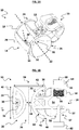
- FIG. 1A illustrates an insulator 10 for an electric fence according to the invention.
- the insulator 10 includes a body 12, having a wire attachment portion 14 at a first end and a post connector portion 16 at its second end.
- the insulator 10 is moulded as a unitary part of an electrically insulating material such as high density polyethylene (HDPE) - although it should be appreciated that other materials may be used.
- HDPE high density polyethylene
- the wire attachment portion 14 includes a passage wall 18 defining a first passage 20.
- the first passage 20 has a first longitudinal axis 22 extending between a first open end 24 and a second open end 26 of the first passage 20.
- a crossmember 28 spans the space between the first open end 24 and the second open end 26 of the first passage 20 on the side of the passage wall 18 distal from the body 12.
- a second passage 30 is defined by a wire retention member in the form of an archway 32, located at a position on the crossmember 28 equidistant from the first open end 24 and the second open end 26 of the first passage 20.
- the second passage 30 has a second longitudinal axis 34, which is substantially orthogonal to the first longitudinal axis 22 in orientation.
- the passage wall 18 has an interior surface 36 defining the shape of the passage 20 , and an exterior surface 38 defining the creepage distance from the first open end 24 and the second open end 26 of the first passage 20 to the body 12.
- the interior surface 36 defining the passage 20 is substantially in the shape of a circular hyperboloid, in which the passage 20 flares out from a narrow central waist region towards the first open end 24 and the second open end 26.
- the length 40 of the first passage 20 is about 45 mm. It is envisaged that this may allow for the production of external corners in a fence line (as will be described below with reference to FIG. 3A and FIG. 3B ) while maintaining a suitable air gap of about 20 mm between the wire and a post (not illustrated in FIG. 1B ) having a width of about 50 mm. It should be appreciated that this is not intended to be limiting, and that the length 40 may be modified depending on the width or configuration of the post it is intended to be used with.
- the diameter 42 of the first open end 24 and the second open end 26 is about 44 mm, while the diameter 44 at the waist region is substantially 7 mm.
- the resulting curvature of the interior surface 36 along the first passage 20 accommodates the entry and exit of a wire at a wide range of angles, while ensuring the wire is not bent beyond a minimum radius of curvature within the first passage 20.
- this configuration is intended to achieve an angle of wire being not more than about 45 degrees exiting from either side of the passage - giving a total of about 90 degrees of change in direction. There is an about 62.5 degree angle before a wire will hit the outer edge of the passage - at which point kinking may occur. This means the wire will always be resting on a smooth radius inside the passage - within that about 45 degree operational limit. It should be appreciated that the angles described are exemplary, and is not intended to be limiting to all embodiments unless expressly stated.
- the exterior surface 38 of the passage wall 18 is shaped to approximate the shape of the interior surface 36. This results in relatively thin wall structure curved to increase the creepage distance to the body 12, and ultimately the post connection portion 16. For example, if a wire (not illustrated) bears against the passage 20 at point 46, dashed line 48 illustrates the creepage path across the exterior surface 38 of the passage wall 18 and body 12. This is significantly greater than if the exterior surface 38 extended straight across to the body 12.
- the post connector portion 16 includes a first arm 50 and a second arm 52, separated by a post receiving space 54.
- the first arm 50 includes a threaded aperture 56
- the second arm 52 includes a stepped aperture 58.
- a fastener 60 having a threaded shank 62 is inserted through the stepped aperture 58, and through one or more apertures in the post to reach the threaded aperture 56.
- a fastener engaging member 64 having external threads 66 is screwed into the threaded aperture 56.
- the threaded shank 62 is in turn screwed into a bore 68 of the fastener engaging member 64, securing the insulator 10 to the post.
- FIG. 2A illustrates the insulator 10 positioned on a conductive fence post 200 , with a first wire 202 passing through the first passage 20 (not illustrated in FIG. 2A , but as seen in FIG. 1A and FIG. 1B ) of the insulator 10.
- the wire 202 can enter and exit the insulator 10 from any angle within the zone designated 'a' without resulting in bending of the wire 202 beyond a radius of curvature set by the passage.
- FIG. 2A illustrates the insulator 10 positioned on a conductive fence post 200 , with a second wire 204 passing through the second passage 30 (not illustrated in FIG. 2B , but as seen in FIG. 1A and FIG. 1B ) of the insulator 10 in a vertical orientation.
- the second wire 204 restricts access to the space 206 between the wire 204 and the leading edge 208 of the post 200 .
- the upper side of the insulator 10 might otherwise be used as a platform for attempting to scale the fence, or the insulator 10 used as an anchor point for hooking horizontal wires (not illustrated) from above, or below.
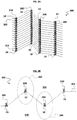
- FIG. 3A illustrates an electric fence system 300 , including a series of vertical fence posts 200 .
- a plurality of insulators 10 are secured to each fence post 200 .
- Wires 202 are passed through the first passage 20 (not clearly seen in FIG. 3A , but as illustrated in FIG. 1A and FIG. 1B ) of each insulator 10 to provide a series of spaced wires 202 which form a barrier.
- FIG. 3B illustrates the electric fence system 300 from a birds-eye view, from which it may be seen that the insulators 10 have been able to accommodate both an internal corner (designated by dashed area 302 ) and an external corner (designated by dashed area 304 ) while ensuring that all of the fence posts are located on a first side 306 of the fence system 300 with the wire 202 on the other side 308 .
Landscapes
- Engineering & Computer Science (AREA)
- Architecture (AREA)
- Civil Engineering (AREA)
- Structural Engineering (AREA)
- Insulators (AREA)
- Life Sciences & Earth Sciences (AREA)
- Environmental Sciences (AREA)
- Animal Husbandry (AREA)
- Biodiversity & Conservation Biology (AREA)
- Catching Or Destruction (AREA)
Claims (12)
- Isolator (10) für einen elektrischen Zaun mit mindestens einem Draht, wobei der Isolator (10) folgendes umfasst:einen Körper (12) mit einem ersten Ende und einem zweiten Ende;einen Drahtbefestigungsabschnitt (14), der an dem ersten Ende des Körpers (12) angeordnet ist;einen Pfostenverbindungsabschnitt (16) an dem zweiten Ende des Körpers (12) zum Verbinden des Isolators (10) mit einem Zaunpfosten (200) bei einer Verwendung,wobei der Drahtbefestigungsabschnitt (14) einen Durchgang (20) aufweist, der durch den Drahtbefestigungsabschnitt (14) verläuft,wobei der Durchgang (20) ein erstes offenes Ende (24), ein zweites offenes Ende (26) und einen Taillenbereich zwischen dem ersten offenen Ende (24) und dem zweiten offenen Ende (26) aufweist,wobei der Durchmesser des Durchgangs (20) an dem ersten offenen Ende (24) und der Durchmesser des zweiten offenen Endes (26) beide größer sind als im Taillenbereich,wobei sich der Durchgang (20) von dem schmalen zentralen Taillenbereich zu dem ersten offenen Ende (24) und dem zweiten offenen Ende (26) in einer gekrümmten Aufweitung aufweitet,wobei der Drahtbefestigungsabschnitt (14) eine Wand (18) mit einer Innenfläche (36), welche den Durchgang (20) umschreibt, und einer Außenfläche (38) aufweist, wobei mindestens ein Teil der Außenfläche (38) der Wand (18) zwischen dem Durchgang (20) und dem Körper (12) des Isolators (10) so geformt ist, dass er der Form der Innenfläche (36) der Wand (18) nahekommt,wobei der Isolator (10) dadurch gekennzeichnet ist, dass:der Körper (12), der Drahtbefestigungsabschnitt (14) und der Pfostenverbindungsabschnitt (16) aus einem elektrisch isolierenden Material hergestellt sind, wobei der Isolator (10) im Ganzen als ein einheitliches Teil gegossen ist, undwobei der Körper (12) derart mit der Außenfläche (38) an dem Taillenbereich verbunden ist, dass eine elektrische Kriechstrecke von dem Durchgang (20) zu einem Pfosten, an welchem der Isolator (10) bei der Verwendung befestigt ist, entlang der Außenfläche (38) und über den Körper (12) verläuft.
- Isolator (10) nach Anspruch 1, wobei der Querschnitt des Durchgangs (20) über dessen Länge im Wesentlichen kreisförmig ist.
- Isolator (10) nach Anspruch 1 oder Anspruch 2, wobei der Durchgang (20) im Wesentlichen die Form eines Hyperboloids aufweist.
- Isolator (10) nach einem der Ansprüche 1 bis 3, wobei der Durchmesser des Durchgangs (20) an dem ersten offenen Ende (24) und an dem zweiten offenen Ende (26) ungefähr 40 mm bis 50 mm beträgt, wobei der Durchmesser des Durchgangs (20) an dem ersten offenen Ende (24) und an dem zweiten offenen Ende (26) vorzugsweise weniger als ungefähr 45 mm beträgt.
- Isolator (10) nach einem der Ansprüche 1 bis 4, wobei die Länge des Durchgangs (20) zwischen dem ersten offenen Ende (24) und dem zweiten offenen Ende (26) ungefähr 40 mm bis 50 mm beträgt, wobei die Länge des Durchgangs (20) zwischen dem ersten offenen Ende (24) und dem zweiten offenen Ende (26) vorzugsweise ungefähr 44 mm beträgt.
- Isolator (10) nach einem der Ansprüche 1 bis 5, wobei die Dicke mindestens eines Teils der Außenfläche (38) der Wand (18) zwischen dem Durchgang (20) und dem Körper (12) des Isolators (10) weniger als ungefähr 3 mm beträgt, wobei die Dicke mindestens eines Teils der Außenfläche (38) der Wand (18) zwischen dem Durchgang (20) und dem Körper (12) des Isolators (10) vorzugsweise weniger als ungefähr 1 mm beträgt.
- Isolator (10) nach einem der Ansprüche 1 bis 6, wobei der Durchgang (20) eine erste Längsachse (22) zwischen dem ersten offenen Ende (24) und dem zweiten offenen Ende (26) aufweist und der Drahtbefestigungsabschnitt (14) einen zweiten Durchgang (30) mit einer zweiten Längsachse (34) quer zur ersten Längsachse (22) aufweist, wobei der zweite Durchgang (30) in Bezug auf den Durchgang (20) mit der ersten Längsachse (22) vorzugsweise an einer von dem Körper (12) entfernten Position angeordnet ist.
- Isolator (10) nach einem der Ansprüche 1 bis 7, wobei der Drahtbefestigungsabschnitt (14) eine Querstrebe (28) an einer Außenfläche (38) des Drahtbefestigungsabschnitts (14) fern von dem Körper (12) aufweist, wobei sich die Querstrebe (28) zwischen dem ersten offenen Ende (24) und dem zweiten offenen Ende (26) des Durchgangs (20) erstreckt.
- Elektrozaunsystem, umfassend:mindestens einen Zaunpfosten (200);mindestens einen an dem Zaunpfosten (200) zu befestigenden Isolator (10), wobei der mindestens eine Isolator (10) ein Isolator (10) nach einem der Ansprüche 1 bis 8 ist; undmindestens eine Zaunleitung (202), welche dazu vorgesehen ist, durch den Durchgang (20) des Drahtbefestigungsabschnitts (14) des Isolators (10) zu verlaufen.
- Elektrozaunsystem nach Anspruch 9, wobei:der Durchgang (20) des mindestens einen Isolators (10) eine erste Längsachse zwischen dem ersten offenen Ende (24) und dem zweiten offenen Ende (26) aufweist, und der Drahtbefestigungsabschnitt (14) einen zweiten Durchgang (30) mit einer zweiten Längsachse (34) quer zur ersten Längsachse (22) aufweist, unddas Elektrozaunsystem eine zweite Zaunleitung (204) umfasst, welche dazu vorgesehen ist, durch den zweiten Durchgang (30) zu verlaufen.
- Verfahren zum Installieren eines elektrischen Zaunsystems, das die folgenden Schritte umfasst:Befestigen mindestens eines Isolators (10) an einem Zaunpfosten (200), wobei der mindestens eine Isolator (10) ein Isolator (10) nach einem der Ansprüche 1 bis 8 ist; undAbstützen mindestens einer Zaunleitung (202) an dem Drahtbefestigungsabschnitt (14) des Isolators (10), indem die Zaunleitung durch den Durchgang (20) geführt wird.
- Verfahren nach Anspruch 11, wobei der Durchgang (20) des mindestens einen Isolators (10) eine erste Längsachse (22) zwischen dem ersten offenen Ende (24) und dem zweiten offenen Ende (26) aufweist und der Drahtbefestigungsabschnitt (14) einen zweiten Durchgang (30) mit einer zweiten Längsachse (34) quer zu der ersten Längsachse (22) aufweist, und
das Verfahren das Durchführen einer zweiten Zaunleitung (204) durch den zweiten Durchgang (30) umfasst, um ein vertikales Zaunelement des Zaunsystems zu bilden.
Applications Claiming Priority (2)
| Application Number | Priority Date | Filing Date | Title |
|---|---|---|---|
| NZ71228115 | 2015-09-14 | ||
| PCT/NZ2016/050148 WO2017048136A1 (en) | 2015-09-14 | 2016-09-14 | An electric fence insulator |
Publications (3)
| Publication Number | Publication Date |
|---|---|
| EP3350815A1 EP3350815A1 (de) | 2018-07-25 |
| EP3350815A4 EP3350815A4 (de) | 2019-04-10 |
| EP3350815B1 true EP3350815B1 (de) | 2021-06-16 |
Family
ID=58289478
Family Applications (1)
| Application Number | Title | Priority Date | Filing Date |
|---|---|---|---|
| EP16846940.1A Active EP3350815B1 (de) | 2015-09-14 | 2016-09-14 | Elektrozaunisolator |
Country Status (6)
| Country | Link |
|---|---|
| US (1) | US11075024B2 (de) |
| EP (1) | EP3350815B1 (de) |
| AU (1) | AU2016324692B2 (de) |
| CA (1) | CA3037186C (de) |
| WO (1) | WO2017048136A1 (de) |
| ZA (1) | ZA201802362B (de) |
Families Citing this family (3)
| Publication number | Priority date | Publication date | Assignee | Title |
|---|---|---|---|---|
| AU2016225840B2 (en) * | 2015-09-21 | 2021-10-21 | Illinois Tool Works Inc. | Tool and tool attachment |
| US11033000B2 (en) * | 2017-05-08 | 2021-06-15 | ES Robbins Corporation | Electric fence connection system |
| AU2021105576A4 (en) * | 2021-05-24 | 2021-10-14 | The Trustee for SUTHERLAND TRUST | Fence Device |
Family Cites Families (54)
| Publication number | Priority date | Publication date | Assignee | Title |
|---|---|---|---|---|
| DE957956C (de) * | 1957-01-24 | Utma-Elektrowerk GmbH, Eutm (Holst) | Rohrformiger Isolator fur Elektroweidezaundrahte | |
| US1213201A (en) * | 1913-12-20 | 1917-01-23 | Donald Hutchinson Patents Ltd | Fastener for fencing-wires. |
| US1525229A (en) | 1919-05-22 | 1925-02-03 | Charles S Cotton | Means for mounting insulator pins |
| US1821222A (en) | 1929-12-30 | 1931-09-01 | Line Material Co | Insulator |
| US1992284A (en) | 1932-07-29 | 1935-02-26 | William C Banks | Bracket insulator |
| US2138571A (en) | 1936-11-20 | 1938-11-29 | Bell Telephone Labor Inc | Insulator |
| US2468985A (en) * | 1943-11-26 | 1949-05-03 | Goodrich Co B F | Resilient connection and method of making same |
| US2438419A (en) * | 1945-10-22 | 1948-03-23 | Paul A Schmidt | Insulator |
| US2537719A (en) | 1948-10-27 | 1951-01-09 | Oscar W Tuepker | Insulator and support for electrically charged fence wires |
| DE856472C (de) * | 1950-10-18 | 1952-11-20 | Walter Bueschen | Hochspannungs-Weidezaunisolator |
| DE903831C (de) * | 1951-12-05 | 1954-02-11 | Walter Bueschen | Hochspannungsisolator, insbesondere fuer elektrische Weidezaeune |
| FR1222403A (fr) * | 1952-11-12 | 1960-06-09 | Isolateur pour clôtures électriques | |
| US2858106A (en) * | 1954-09-20 | 1958-10-28 | William G Anton | Guide for flexible lines |
| FR1220852A (fr) * | 1958-12-12 | 1960-05-30 | Isolateur pour lignes électriques aériennes | |
| FR1276725A (fr) * | 1960-10-11 | 1961-11-24 | Expl De Brevets J Legrand Et C | Nouvel isolateur pour lignes électriques |
| US3272463A (en) | 1964-11-03 | 1966-09-13 | Malleable Iron Fittings Co | Insulator bracket |
| US3240870A (en) | 1965-03-10 | 1966-03-15 | Ohio Brass Co | Suspension apparatus for bundle conductors |
| US3749820A (en) * | 1972-07-14 | 1973-07-31 | H Langlie | Electric fence insulator |
| US3749819A (en) * | 1972-10-30 | 1973-07-31 | Dare Products Inc | Coreless double flanged insulation |
| NZ175274A (en) | 1974-08-28 | 1979-12-11 | D S M Phillips | Insulator with end flanges for shedding water passing along fence wire |
| FR2299707A1 (fr) * | 1975-02-03 | 1976-08-27 | Maneville Guy De | Nouveau support isolant pour clotures electriques |
| US4028489A (en) * | 1975-12-12 | 1977-06-07 | Berg Jr Albert T | Plastic nail-on electric fence insulator |
| US4049905A (en) * | 1976-03-29 | 1977-09-20 | Sta-Tite Corporation | Insulator for electric fences |
| US4077611A (en) * | 1976-10-26 | 1978-03-07 | Dare Products, Incorporated | Fence wire mount and insulator |
| US4160540A (en) | 1977-12-27 | 1979-07-10 | Lindsey Manufacturing Company | Fast action disconnect for use on a dog nut of a power line insulator and the like |
| US4263477A (en) * | 1979-12-26 | 1981-04-21 | Dare Products, Inc. | Electric fence insulator |
| USD283612S (en) | 1983-03-02 | 1986-04-29 | Timmington David A | Anode for cathodic protection of chain links |
| US4599488A (en) * | 1985-09-12 | 1986-07-08 | Dare Products, Inc. | Universal nail-on insulator |
| US4771137A (en) * | 1987-10-13 | 1988-09-13 | Thompson Donald G | Electric fence wire insulator |
| WO1990006674A1 (en) * | 1988-12-20 | 1990-06-28 | Boral Limited | Fabricated electric fencing |
| USD315334S (en) | 1989-07-07 | 1991-03-12 | Kitagawa Industries Co., Ltd. | Absorber of electric noise |
| USD375079S (en) | 1995-02-21 | 1996-10-29 | Maclean-Fogg Company | Power line insulator |
| US6290190B1 (en) * | 1995-12-21 | 2001-09-18 | Gallagher Group Limited | Support device |
| US6056245A (en) * | 1996-01-25 | 2000-05-02 | Phillip E. White | Flared cable support for telecommunication system installations |
| USD392616S (en) | 1996-04-03 | 1998-03-24 | Serge Gagne | Electrical insulator having sheds |
| US5945636A (en) | 1996-04-22 | 1999-08-31 | Hubbell Incorporated | Electrical insulators with mechanical core and dielectric sheath |
| US5981878A (en) | 1996-04-22 | 1999-11-09 | Hubbell Incorporated | Polymer insulators with metal caps |
| USD452136S1 (en) | 1996-12-20 | 2001-12-18 | Avon Inflatables Limited | Rope retainer |
| USD421958S (en) | 1998-03-10 | 2000-03-28 | Pratt Hugh M | Load insulator |
| US6027082A (en) | 1998-11-03 | 2000-02-22 | Cai Unit, Inc. | Convertible electric utility cross arm insulator unit |
| CA2286419A1 (en) | 1999-04-29 | 2000-10-29 | Eric White | Insulator for electric fencing |
| CA2270747A1 (en) | 1999-04-29 | 2000-10-29 | Eric White | Insulator for electric fencing |
| USD463971S1 (en) | 2000-04-19 | 2002-10-08 | Dart Industries Inc. | Wall hook with central slot |
| USD438779S1 (en) | 2000-06-26 | 2001-03-13 | We Cousins Company | High roller stringing block |
| US6667442B1 (en) | 2002-07-25 | 2003-12-23 | Patent Holding Company, Ltd. | Electric utility cross arm |
| US7318567B2 (en) | 2005-03-07 | 2008-01-15 | Belkin International, Inc. | Cable management device |
| USD571190S1 (en) | 2006-06-15 | 2008-06-17 | Claber S.P.A. | Wall hanger for watering hose and hose fittings |
| US20080057215A1 (en) | 2006-08-22 | 2008-03-06 | Mccollough Norman | Method of increasing puncture strength and high voltage corona erosion resistance of medium voltage polymer insulators |
| US20130032379A1 (en) | 2009-10-23 | 2013-02-07 | Alf Baker | Integrated clamp insulators |
| AU2012231770A1 (en) | 2011-03-18 | 2013-06-20 | Onesteel Wire Pty Limited | Apparatus, method and system for securing a strand to a post |
| USD744968S1 (en) | 2013-03-19 | 2015-12-08 | Phoenix Contact Gmbh & Co. Kg | Electrical housing |
| AU349534S (en) | 2013-04-22 | 2013-07-01 | Pacific Polymers Pty Ltd | Cut-out insulator for high tension electrical circuits |
| CN108140459B (zh) | 2015-07-30 | 2020-11-06 | 盖拉格尔集团有限公司 | 电围栏绝缘体 |
| US9679682B2 (en) | 2015-08-25 | 2017-06-13 | John Wall, Inc. | Fence post insulator for electrifiable plastic coated wire |
-
2016
- 2016-09-14 EP EP16846940.1A patent/EP3350815B1/de active Active
- 2016-09-14 CA CA3037186A patent/CA3037186C/en active Active
- 2016-09-14 WO PCT/NZ2016/050148 patent/WO2017048136A1/en not_active Ceased
- 2016-09-14 AU AU2016324692A patent/AU2016324692B2/en active Active
- 2016-09-14 US US15/760,167 patent/US11075024B2/en active Active
-
2018
- 2018-04-11 ZA ZA2018/02362A patent/ZA201802362B/en unknown
Non-Patent Citations (1)
| Title |
|---|
| None * |
Also Published As
| Publication number | Publication date |
|---|---|
| ZA201802362B (en) | 2020-10-28 |
| EP3350815A1 (de) | 2018-07-25 |
| EP3350815A4 (de) | 2019-04-10 |
| AU2016324692A1 (en) | 2018-05-10 |
| AU2016324692B2 (en) | 2021-11-04 |
| US20180254128A1 (en) | 2018-09-06 |
| US11075024B2 (en) | 2021-07-27 |
| CA3037186C (en) | 2023-05-23 |
| NZ741537A (en) | 2024-05-31 |
| CA3037186A1 (en) | 2017-03-23 |
| WO2017048136A1 (en) | 2017-03-23 |
Similar Documents
| Publication | Publication Date | Title |
|---|---|---|
| AU2021266334B2 (en) | An Electric Fence Insulator | |
| EP3350815B1 (de) | Elektrozaunisolator | |
| US10439376B2 (en) | Wire harness | |
| KR20120024498A (ko) | 개선된 성능을 갖는 터미널 포스트 | |
| US7216852B2 (en) | Multi-position wire insulator and fence support bracket | |
| US9322536B1 (en) | Large capacity gusseted tube and traffic control assembly comprising same | |
| US5412158A (en) | Electric fence wire insulation | |
| US7511227B2 (en) | Connectors | |
| US20070063176A1 (en) | Support for supporting cable net, and security fence using the same | |
| US10535238B2 (en) | Barbed tape and security sensor assembly | |
| US4708322A (en) | Electrified fence gate | |
| JP2007305307A (ja) | 電気柵用電線碍子 | |
| JP2015050966A (ja) | 架線金具 | |
| GB2295627A (en) | Spacer for electric fencing | |
| JPH0441431Y2 (de) | ||
| GB2323108A (en) | Electrified fencing | |
| EP3552284B1 (de) | Kabellegevorrichtung | |
| KR20130000286U (ko) | 도로의 가드레일용 침입방지판 구조 | |
| AU2018200173A1 (en) | Electric fence insulator | |
| GB2603941A (en) | A Gate Device | |
| BR102018015064A2 (pt) | elemento separador de massa para emprego na moldagem de poste auto aterrado | |
| GB2119144A (en) | Security alarms in association with concrete structures | |
| ZA200806592B (en) | Security fencing |
Legal Events
| Date | Code | Title | Description |
|---|---|---|---|
| STAA | Information on the status of an ep patent application or granted ep patent |
Free format text: STATUS: THE INTERNATIONAL PUBLICATION HAS BEEN MADE |
|
| PUAI | Public reference made under article 153(3) epc to a published international application that has entered the european phase |
Free format text: ORIGINAL CODE: 0009012 |
|
| STAA | Information on the status of an ep patent application or granted ep patent |
Free format text: STATUS: REQUEST FOR EXAMINATION WAS MADE |
|
| 17P | Request for examination filed |
Effective date: 20180412 |
|
| AK | Designated contracting states |
Kind code of ref document: A1 Designated state(s): AL AT BE BG CH CY CZ DE DK EE ES FI FR GB GR HR HU IE IS IT LI LT LU LV MC MK MT NL NO PL PT RO RS SE SI SK SM TR |
|
| AX | Request for extension of the european patent |
Extension state: BA ME |
|
| DAV | Request for validation of the european patent (deleted) | ||
| DAX | Request for extension of the european patent (deleted) | ||
| REG | Reference to a national code |
Ref country code: DE Ref legal event code: R079 Ref document number: 602016059493 Country of ref document: DE Free format text: PREVIOUS MAIN CLASS: H01B0017000000 Ipc: H01B0017140000 |
|
| A4 | Supplementary search report drawn up and despatched |
Effective date: 20190307 |
|
| RIC1 | Information provided on ipc code assigned before grant |
Ipc: H01B 17/14 20060101AFI20190301BHEP Ipc: A01K 3/00 20060101ALI20190301BHEP Ipc: E04H 17/10 20060101ALI20190301BHEP |
|
| STAA | Information on the status of an ep patent application or granted ep patent |
Free format text: STATUS: EXAMINATION IS IN PROGRESS |
|
| 17Q | First examination report despatched |
Effective date: 20200325 |
|
| GRAP | Despatch of communication of intention to grant a patent |
Free format text: ORIGINAL CODE: EPIDOSNIGR1 |
|
| STAA | Information on the status of an ep patent application or granted ep patent |
Free format text: STATUS: GRANT OF PATENT IS INTENDED |
|
| INTG | Intention to grant announced |
Effective date: 20201218 |
|
| GRAJ | Information related to disapproval of communication of intention to grant by the applicant or resumption of examination proceedings by the epo deleted |
Free format text: ORIGINAL CODE: EPIDOSDIGR1 |
|
| STAA | Information on the status of an ep patent application or granted ep patent |
Free format text: STATUS: EXAMINATION IS IN PROGRESS |
|
| GRAS | Grant fee paid |
Free format text: ORIGINAL CODE: EPIDOSNIGR3 |
|
| STAA | Information on the status of an ep patent application or granted ep patent |
Free format text: STATUS: GRANT OF PATENT IS INTENDED |
|
| GRAP | Despatch of communication of intention to grant a patent |
Free format text: ORIGINAL CODE: EPIDOSNIGR1 |
|
| GRAA | (expected) grant |
Free format text: ORIGINAL CODE: 0009210 |
|
| STAA | Information on the status of an ep patent application or granted ep patent |
Free format text: STATUS: THE PATENT HAS BEEN GRANTED |
|
| INTC | Intention to grant announced (deleted) | ||
| INTG | Intention to grant announced |
Effective date: 20210506 |
|
| AK | Designated contracting states |
Kind code of ref document: B1 Designated state(s): AL AT BE BG CH CY CZ DE DK EE ES FI FR GB GR HR HU IE IS IT LI LT LU LV MC MK MT NL NO PL PT RO RS SE SI SK SM TR |
|
| REG | Reference to a national code |
Ref country code: GB Ref legal event code: FG4D |
|
| REG | Reference to a national code |
Ref country code: CH Ref legal event code: EP |
|
| REG | Reference to a national code |
Ref country code: DE Ref legal event code: R096 Ref document number: 602016059493 Country of ref document: DE |
|
| REG | Reference to a national code |
Ref country code: AT Ref legal event code: REF Ref document number: 1403010 Country of ref document: AT Kind code of ref document: T Effective date: 20210715 |
|
| REG | Reference to a national code |
Ref country code: IE Ref legal event code: FG4D |
|
| REG | Reference to a national code |
Ref country code: LT Ref legal event code: MG9D |
|
| PG25 | Lapsed in a contracting state [announced via postgrant information from national office to epo] |
Ref country code: HR Free format text: LAPSE BECAUSE OF FAILURE TO SUBMIT A TRANSLATION OF THE DESCRIPTION OR TO PAY THE FEE WITHIN THE PRESCRIBED TIME-LIMIT Effective date: 20210616 Ref country code: BG Free format text: LAPSE BECAUSE OF FAILURE TO SUBMIT A TRANSLATION OF THE DESCRIPTION OR TO PAY THE FEE WITHIN THE PRESCRIBED TIME-LIMIT Effective date: 20210916 Ref country code: LT Free format text: LAPSE BECAUSE OF FAILURE TO SUBMIT A TRANSLATION OF THE DESCRIPTION OR TO PAY THE FEE WITHIN THE PRESCRIBED TIME-LIMIT Effective date: 20210616 Ref country code: FI Free format text: LAPSE BECAUSE OF FAILURE TO SUBMIT A TRANSLATION OF THE DESCRIPTION OR TO PAY THE FEE WITHIN THE PRESCRIBED TIME-LIMIT Effective date: 20210616 |
|
| PGFP | Annual fee paid to national office [announced via postgrant information from national office to epo] |
Ref country code: NL Payment date: 20210914 Year of fee payment: 6 |
|
| REG | Reference to a national code |
Ref country code: AT Ref legal event code: MK05 Ref document number: 1403010 Country of ref document: AT Kind code of ref document: T Effective date: 20210616 |
|
| REG | Reference to a national code |
Ref country code: NL Ref legal event code: MP Effective date: 20210616 |
|
| PG25 | Lapsed in a contracting state [announced via postgrant information from national office to epo] |
Ref country code: LV Free format text: LAPSE BECAUSE OF FAILURE TO SUBMIT A TRANSLATION OF THE DESCRIPTION OR TO PAY THE FEE WITHIN THE PRESCRIBED TIME-LIMIT Effective date: 20210616 Ref country code: GR Free format text: LAPSE BECAUSE OF FAILURE TO SUBMIT A TRANSLATION OF THE DESCRIPTION OR TO PAY THE FEE WITHIN THE PRESCRIBED TIME-LIMIT Effective date: 20210917 Ref country code: RS Free format text: LAPSE BECAUSE OF FAILURE TO SUBMIT A TRANSLATION OF THE DESCRIPTION OR TO PAY THE FEE WITHIN THE PRESCRIBED TIME-LIMIT Effective date: 20210616 Ref country code: SE Free format text: LAPSE BECAUSE OF FAILURE TO SUBMIT A TRANSLATION OF THE DESCRIPTION OR TO PAY THE FEE WITHIN THE PRESCRIBED TIME-LIMIT Effective date: 20210616 Ref country code: NO Free format text: LAPSE BECAUSE OF FAILURE TO SUBMIT A TRANSLATION OF THE DESCRIPTION OR TO PAY THE FEE WITHIN THE PRESCRIBED TIME-LIMIT Effective date: 20210916 |
|
| PG25 | Lapsed in a contracting state [announced via postgrant information from national office to epo] |
Ref country code: SK Free format text: LAPSE BECAUSE OF FAILURE TO SUBMIT A TRANSLATION OF THE DESCRIPTION OR TO PAY THE FEE WITHIN THE PRESCRIBED TIME-LIMIT Effective date: 20210616 Ref country code: SM Free format text: LAPSE BECAUSE OF FAILURE TO SUBMIT A TRANSLATION OF THE DESCRIPTION OR TO PAY THE FEE WITHIN THE PRESCRIBED TIME-LIMIT Effective date: 20210616 Ref country code: CZ Free format text: LAPSE BECAUSE OF FAILURE TO SUBMIT A TRANSLATION OF THE DESCRIPTION OR TO PAY THE FEE WITHIN THE PRESCRIBED TIME-LIMIT Effective date: 20210616 Ref country code: EE Free format text: LAPSE BECAUSE OF FAILURE TO SUBMIT A TRANSLATION OF THE DESCRIPTION OR TO PAY THE FEE WITHIN THE PRESCRIBED TIME-LIMIT Effective date: 20210616 Ref country code: AT Free format text: LAPSE BECAUSE OF FAILURE TO SUBMIT A TRANSLATION OF THE DESCRIPTION OR TO PAY THE FEE WITHIN THE PRESCRIBED TIME-LIMIT Effective date: 20210616 Ref country code: RO Free format text: LAPSE BECAUSE OF FAILURE TO SUBMIT A TRANSLATION OF THE DESCRIPTION OR TO PAY THE FEE WITHIN THE PRESCRIBED TIME-LIMIT Effective date: 20210616 Ref country code: PT Free format text: LAPSE BECAUSE OF FAILURE TO SUBMIT A TRANSLATION OF THE DESCRIPTION OR TO PAY THE FEE WITHIN THE PRESCRIBED TIME-LIMIT Effective date: 20211018 Ref country code: NL Free format text: LAPSE BECAUSE OF FAILURE TO SUBMIT A TRANSLATION OF THE DESCRIPTION OR TO PAY THE FEE WITHIN THE PRESCRIBED TIME-LIMIT Effective date: 20210616 Ref country code: ES Free format text: LAPSE BECAUSE OF FAILURE TO SUBMIT A TRANSLATION OF THE DESCRIPTION OR TO PAY THE FEE WITHIN THE PRESCRIBED TIME-LIMIT Effective date: 20210616 |
|
| PG25 | Lapsed in a contracting state [announced via postgrant information from national office to epo] |
Ref country code: PL Free format text: LAPSE BECAUSE OF FAILURE TO SUBMIT A TRANSLATION OF THE DESCRIPTION OR TO PAY THE FEE WITHIN THE PRESCRIBED TIME-LIMIT Effective date: 20210616 |
|
| REG | Reference to a national code |
Ref country code: DE Ref legal event code: R097 Ref document number: 602016059493 Country of ref document: DE |
|
| PLBE | No opposition filed within time limit |
Free format text: ORIGINAL CODE: 0009261 |
|
| STAA | Information on the status of an ep patent application or granted ep patent |
Free format text: STATUS: NO OPPOSITION FILED WITHIN TIME LIMIT |
|
| PG25 | Lapsed in a contracting state [announced via postgrant information from national office to epo] |
Ref country code: DK Free format text: LAPSE BECAUSE OF FAILURE TO SUBMIT A TRANSLATION OF THE DESCRIPTION OR TO PAY THE FEE WITHIN THE PRESCRIBED TIME-LIMIT Effective date: 20210616 |
|
| REG | Reference to a national code |
Ref country code: CH Ref legal event code: PL |
|
| 26N | No opposition filed |
Effective date: 20220317 |
|
| PG25 | Lapsed in a contracting state [announced via postgrant information from national office to epo] |
Ref country code: MC Free format text: LAPSE BECAUSE OF FAILURE TO SUBMIT A TRANSLATION OF THE DESCRIPTION OR TO PAY THE FEE WITHIN THE PRESCRIBED TIME-LIMIT Effective date: 20210616 Ref country code: AL Free format text: LAPSE BECAUSE OF FAILURE TO SUBMIT A TRANSLATION OF THE DESCRIPTION OR TO PAY THE FEE WITHIN THE PRESCRIBED TIME-LIMIT Effective date: 20210616 |
|
| PG25 | Lapsed in a contracting state [announced via postgrant information from national office to epo] |
Ref country code: LU Free format text: LAPSE BECAUSE OF NON-PAYMENT OF DUE FEES Effective date: 20210914 Ref country code: IT Free format text: LAPSE BECAUSE OF FAILURE TO SUBMIT A TRANSLATION OF THE DESCRIPTION OR TO PAY THE FEE WITHIN THE PRESCRIBED TIME-LIMIT Effective date: 20210616 |
|
| PG25 | Lapsed in a contracting state [announced via postgrant information from national office to epo] |
Ref country code: LI Free format text: LAPSE BECAUSE OF NON-PAYMENT OF DUE FEES Effective date: 20210930 Ref country code: CH Free format text: LAPSE BECAUSE OF NON-PAYMENT OF DUE FEES Effective date: 20210930 |
|
| PGFP | Annual fee paid to national office [announced via postgrant information from national office to epo] |
Ref country code: IE Payment date: 20220926 Year of fee payment: 7 |
|
| PGFP | Annual fee paid to national office [announced via postgrant information from national office to epo] |
Ref country code: BE Payment date: 20220927 Year of fee payment: 7 |
|
| PG25 | Lapsed in a contracting state [announced via postgrant information from national office to epo] |
Ref country code: HU Free format text: LAPSE BECAUSE OF FAILURE TO SUBMIT A TRANSLATION OF THE DESCRIPTION OR TO PAY THE FEE WITHIN THE PRESCRIBED TIME-LIMIT; INVALID AB INITIO Effective date: 20160914 |
|
| PG25 | Lapsed in a contracting state [announced via postgrant information from national office to epo] |
Ref country code: CY Free format text: LAPSE BECAUSE OF FAILURE TO SUBMIT A TRANSLATION OF THE DESCRIPTION OR TO PAY THE FEE WITHIN THE PRESCRIBED TIME-LIMIT Effective date: 20210616 |
|
| PG25 | Lapsed in a contracting state [announced via postgrant information from national office to epo] |
Ref country code: MK Free format text: LAPSE BECAUSE OF FAILURE TO SUBMIT A TRANSLATION OF THE DESCRIPTION OR TO PAY THE FEE WITHIN THE PRESCRIBED TIME-LIMIT Effective date: 20210616 |
|
| REG | Reference to a national code |
Ref country code: BE Ref legal event code: MM Effective date: 20230930 |
|
| PG25 | Lapsed in a contracting state [announced via postgrant information from national office to epo] |
Ref country code: TR Free format text: LAPSE BECAUSE OF FAILURE TO SUBMIT A TRANSLATION OF THE DESCRIPTION OR TO PAY THE FEE WITHIN THE PRESCRIBED TIME-LIMIT Effective date: 20210616 |
|
| REG | Reference to a national code |
Ref country code: IE Ref legal event code: MM4A |
|
| PG25 | Lapsed in a contracting state [announced via postgrant information from national office to epo] |
Ref country code: IE Free format text: LAPSE BECAUSE OF NON-PAYMENT OF DUE FEES Effective date: 20230914 |
|
| PG25 | Lapsed in a contracting state [announced via postgrant information from national office to epo] |
Ref country code: IE Free format text: LAPSE BECAUSE OF NON-PAYMENT OF DUE FEES Effective date: 20230914 |
|
| PG25 | Lapsed in a contracting state [announced via postgrant information from national office to epo] |
Ref country code: BE Free format text: LAPSE BECAUSE OF NON-PAYMENT OF DUE FEES Effective date: 20230930 |
|
| PG25 | Lapsed in a contracting state [announced via postgrant information from national office to epo] |
Ref country code: MT Free format text: LAPSE BECAUSE OF FAILURE TO SUBMIT A TRANSLATION OF THE DESCRIPTION OR TO PAY THE FEE WITHIN THE PRESCRIBED TIME-LIMIT Effective date: 20210616 |
|
| PGFP | Annual fee paid to national office [announced via postgrant information from national office to epo] |
Ref country code: DE Payment date: 20250916 Year of fee payment: 10 |
|
| PGFP | Annual fee paid to national office [announced via postgrant information from national office to epo] |
Ref country code: GB Payment date: 20250915 Year of fee payment: 10 |
|
| PGFP | Annual fee paid to national office [announced via postgrant information from national office to epo] |
Ref country code: FR Payment date: 20250916 Year of fee payment: 10 |