EP3350614B1 - Implementation of the focal plane 2d apd array for hyperion lidar system - Google Patents
Implementation of the focal plane 2d apd array for hyperion lidar system Download PDFInfo
- Publication number
- EP3350614B1 EP3350614B1 EP16774759.1A EP16774759A EP3350614B1 EP 3350614 B1 EP3350614 B1 EP 3350614B1 EP 16774759 A EP16774759 A EP 16774759A EP 3350614 B1 EP3350614 B1 EP 3350614B1
- Authority
- EP
- European Patent Office
- Prior art keywords
- fiber optic
- free end
- optic cable
- light sensor
- sensor array
- Prior art date
- Legal status (The legal status is an assumption and is not a legal conclusion. Google has not performed a legal analysis and makes no representation as to the accuracy of the status listed.)
- Active
Links
- 239000000835 fiber Substances 0.000 claims description 48
- 238000000034 method Methods 0.000 claims description 34
- 239000000919 ceramic Substances 0.000 claims description 17
- 238000000098 azimuthal photoelectron diffraction Methods 0.000 claims 2
- 238000004891 communication Methods 0.000 description 8
- 238000010586 diagram Methods 0.000 description 7
- 238000012545 processing Methods 0.000 description 7
- 238000005259 measurement Methods 0.000 description 6
- 230000015654 memory Effects 0.000 description 6
- 230000008569 process Effects 0.000 description 5
- 239000000523 sample Substances 0.000 description 4
- 238000010304 firing Methods 0.000 description 3
- 230000006870 function Effects 0.000 description 3
- 238000009434 installation Methods 0.000 description 3
- 238000010295 mobile communication Methods 0.000 description 3
- 230000005540 biological transmission Effects 0.000 description 2
- 230000003287 optical effect Effects 0.000 description 2
- 230000009467 reduction Effects 0.000 description 2
- 230000003936 working memory Effects 0.000 description 2
- 230000001133 acceleration Effects 0.000 description 1
- 230000002411 adverse Effects 0.000 description 1
- 238000003491 array Methods 0.000 description 1
- 230000002238 attenuated effect Effects 0.000 description 1
- 230000008901 benefit Effects 0.000 description 1
- 230000010267 cellular communication Effects 0.000 description 1
- 230000001413 cellular effect Effects 0.000 description 1
- 230000008859 change Effects 0.000 description 1
- 230000006835 compression Effects 0.000 description 1
- 238000007906 compression Methods 0.000 description 1
- 230000008878 coupling Effects 0.000 description 1
- 238000010168 coupling process Methods 0.000 description 1
- 238000005859 coupling reaction Methods 0.000 description 1
- 230000006837 decompression Effects 0.000 description 1
- 230000001419 dependent effect Effects 0.000 description 1
- 238000001514 detection method Methods 0.000 description 1
- 238000005286 illumination Methods 0.000 description 1
- 238000005305 interferometry Methods 0.000 description 1
- 238000004519 manufacturing process Methods 0.000 description 1
- 230000000704 physical effect Effects 0.000 description 1
- 230000005855 radiation Effects 0.000 description 1
- 230000003595 spectral effect Effects 0.000 description 1
- 239000000126 substance Substances 0.000 description 1
- 230000009466 transformation Effects 0.000 description 1
- 230000001131 transforming effect Effects 0.000 description 1
- 230000000007 visual effect Effects 0.000 description 1
Images


Classifications
-
- G—PHYSICS
- G01—MEASURING; TESTING
- G01S—RADIO DIRECTION-FINDING; RADIO NAVIGATION; DETERMINING DISTANCE OR VELOCITY BY USE OF RADIO WAVES; LOCATING OR PRESENCE-DETECTING BY USE OF THE REFLECTION OR RERADIATION OF RADIO WAVES; ANALOGOUS ARRANGEMENTS USING OTHER WAVES
- G01S17/00—Systems using the reflection or reradiation of electromagnetic waves other than radio waves, e.g. lidar systems
- G01S17/02—Systems using the reflection of electromagnetic waves other than radio waves
- G01S17/06—Systems determining position data of a target
- G01S17/08—Systems determining position data of a target for measuring distance only
- G01S17/10—Systems determining position data of a target for measuring distance only using transmission of interrupted, pulse-modulated waves
- G01S17/14—Systems determining position data of a target for measuring distance only using transmission of interrupted, pulse-modulated waves wherein a voltage or current pulse is initiated and terminated in accordance with the pulse transmission and echo reception respectively, e.g. using counters
-
- G—PHYSICS
- G01—MEASURING; TESTING
- G01S—RADIO DIRECTION-FINDING; RADIO NAVIGATION; DETERMINING DISTANCE OR VELOCITY BY USE OF RADIO WAVES; LOCATING OR PRESENCE-DETECTING BY USE OF THE REFLECTION OR RERADIATION OF RADIO WAVES; ANALOGOUS ARRANGEMENTS USING OTHER WAVES
- G01S17/00—Systems using the reflection or reradiation of electromagnetic waves other than radio waves, e.g. lidar systems
- G01S17/02—Systems using the reflection of electromagnetic waves other than radio waves
- G01S17/06—Systems determining position data of a target
- G01S17/42—Simultaneous measurement of distance and other co-ordinates
-
- G—PHYSICS
- G01—MEASURING; TESTING
- G01S—RADIO DIRECTION-FINDING; RADIO NAVIGATION; DETERMINING DISTANCE OR VELOCITY BY USE OF RADIO WAVES; LOCATING OR PRESENCE-DETECTING BY USE OF THE REFLECTION OR RERADIATION OF RADIO WAVES; ANALOGOUS ARRANGEMENTS USING OTHER WAVES
- G01S7/00—Details of systems according to groups G01S13/00, G01S15/00, G01S17/00
- G01S7/48—Details of systems according to groups G01S13/00, G01S15/00, G01S17/00 of systems according to group G01S17/00
- G01S7/481—Constructional features, e.g. arrangements of optical elements
- G01S7/4816—Constructional features, e.g. arrangements of optical elements of receivers alone
-
- G—PHYSICS
- G01—MEASURING; TESTING
- G01S—RADIO DIRECTION-FINDING; RADIO NAVIGATION; DETERMINING DISTANCE OR VELOCITY BY USE OF RADIO WAVES; LOCATING OR PRESENCE-DETECTING BY USE OF THE REFLECTION OR RERADIATION OF RADIO WAVES; ANALOGOUS ARRANGEMENTS USING OTHER WAVES
- G01S7/00—Details of systems according to groups G01S13/00, G01S15/00, G01S17/00
- G01S7/48—Details of systems according to groups G01S13/00, G01S15/00, G01S17/00 of systems according to group G01S17/00
- G01S7/481—Constructional features, e.g. arrangements of optical elements
- G01S7/4817—Constructional features, e.g. arrangements of optical elements relating to scanning
-
- G—PHYSICS
- G01—MEASURING; TESTING
- G01S—RADIO DIRECTION-FINDING; RADIO NAVIGATION; DETERMINING DISTANCE OR VELOCITY BY USE OF RADIO WAVES; LOCATING OR PRESENCE-DETECTING BY USE OF THE REFLECTION OR RERADIATION OF RADIO WAVES; ANALOGOUS ARRANGEMENTS USING OTHER WAVES
- G01S7/00—Details of systems according to groups G01S13/00, G01S15/00, G01S17/00
- G01S7/48—Details of systems according to groups G01S13/00, G01S15/00, G01S17/00 of systems according to group G01S17/00
- G01S7/481—Constructional features, e.g. arrangements of optical elements
- G01S7/4818—Constructional features, e.g. arrangements of optical elements using optical fibres
-
- G—PHYSICS
- G01—MEASURING; TESTING
- G01S—RADIO DIRECTION-FINDING; RADIO NAVIGATION; DETERMINING DISTANCE OR VELOCITY BY USE OF RADIO WAVES; LOCATING OR PRESENCE-DETECTING BY USE OF THE REFLECTION OR RERADIATION OF RADIO WAVES; ANALOGOUS ARRANGEMENTS USING OTHER WAVES
- G01S7/00—Details of systems according to groups G01S13/00, G01S15/00, G01S17/00
- G01S7/48—Details of systems according to groups G01S13/00, G01S15/00, G01S17/00 of systems according to group G01S17/00
- G01S7/483—Details of pulse systems
- G01S7/486—Receivers
- G01S7/4861—Circuits for detection, sampling, integration or read-out
- G01S7/4863—Detector arrays, e.g. charge-transfer gates
-
- G—PHYSICS
- G02—OPTICS
- G02B—OPTICAL ELEMENTS, SYSTEMS OR APPARATUS
- G02B26/00—Optical devices or arrangements for the control of light using movable or deformable optical elements
- G02B26/08—Optical devices or arrangements for the control of light using movable or deformable optical elements for controlling the direction of light
- G02B26/10—Scanning systems
- G02B26/103—Scanning systems having movable or deformable optical fibres, light guides or waveguides as scanning elements
Definitions
- the subject matter disclosed herein relates to electronic devices, and more particularly to methods, apparatuses, and systems for measuring the distance to an object using light.
- a Lidar also LIDAR, LiDAR, or LADAR, portmanteau of "light” and “radar” is a remote sensing technology that measures distance by illuminating a target with a laser and analyzing the reflected light.
- the ability to accurately range the distance to the objects in the immediate environment is important for many mobile applications, such as indoor mapping and navigation, enhanced photography, or computer vision, etc.
- WO 2007/024221 A1 discloses methods, systems and devices that can determine spatial relationships between a probe and a target surface. Specular reflections from the target surface vary dramatically with small changes in angle between the scanning beam and the target surface, and as the geometry of the beam scanner and light detector of the probe are often known, and as the angle of the light beam projected from a scanner for accurately generating an image, the pattern of spectral light reflected from the light beam directly back to the detector allows the distance between the probe and the target surface, and/or the angular relationship between the probe and the target surface, to be calculated.
- the document US 2002/139920 A1 discloses a minimally invasive, medical, image acquisition system that outputs a light beam or pulse which illuminates a precise spot size.
- a plurality of photon detector detect returning photons from the object, including the spot.
- Pixel resolution is determined by the area of the illumination spot, rather than an area sensed by the detector.
- Depth enhancement is determined by correlating images detected by the respective detectors, or alternatively by a range finding method based on phase difference, time of flight, frequency or interferometry.
- the document US 2014/231647 A1 discloses a system for short-range laser detection and ranging of targets that can provide rapid three-dimensional, e.g., angle, angle, range, scans over a wide field-of-view.
- the disclosed LADAR system can be implemented in an all-fiber configuration.
- the document US 5,317,148 A discloses a scanner for implementation with ladar, and visual band passive IR systems.
- An optic fiber is positioned such that one end thereof is maintained at the focal point of a lens system.
- a permanent magnet is attached to the optic fiber near that end, with the permanent magnet being positioned within a space subjected to varying magnetic fields induced by pairs of orthogonally positioned electromagnets.
- a Lidar device as set forth in claim 1 a method as set forth in claim 8 and a computer-readable medium as set forth in claim 15 are provided.
- Embodiments of the invention are claimed in the dependent claims. Embodiments defined herein which are not covered by the claims may provide examples useful for understanding the invention.
- One aspect of the disclosure is related to a Lidar device, comprising: a vibrating fiber optic cantilever system on a transmit (TX) path; and a two-dimensional (2D) light sensor array on a receive (RX) path.
- TX transmit
- RX receive
- a method for implementing a Lidar device comprising: implementing a vibrating fiber optic cantilever system on a transmit (TX) path; and implementing a two-dimensional (2D) light sensor array on a receive (RX) path.
- a Lidar device comprising: a vibrating fiber optic cantilever means on a transmit (TX) path; and a two-dimensional (2D) light sensing means on a receive (RX) path.
- a non-transitory computer-readable medium comprising code which, when executed by a processor, causes the processor to implement a method comprising: driving a vibrating fiber optic cantilever system on a transmit (TX) path of a Lidar device; and driving a two-dimensional (2D) light sensor array on a receive (RX) path of the Lidar device.
- TX transmit
- RX receive
- Embodiments of the disclosure are related to apparatuses, systems, and methods for measuring distance by illuminating a target with a laser and analyzing the reflected light.
- the device 100 is shown comprising hardware elements that can be electrically coupled via a bus 105 (or may otherwise be in communication, as appropriate).
- the hardware elements may include one or more processors 110, including without limitation one or more general-purpose processors and/or one or more special-purpose processors (such as digital signal processing chips, graphics acceleration processors, and/or the like); one or more input/output devices 115 including without limitation a Lidar 150, a mouse, a keyboard, a speaker, a printer, and/or the like.
- the Lidar 150 may include a hardware Lidar controller.
- the device 100 may further include (and/or be in communication with) one or more non-transitory storage devices 125, which can comprise, without limitation, local and/or network accessible storage, and/or can include, without limitation, a disk drive, a drive array, an optical storage device, solid-state storage device such as a random access memory (“RAM”) and/or a read-only memory (“ROM”), which can be programmable, flash-updateable, and/or the like.
- RAM random access memory
- ROM read-only memory
- Such storage devices may be configured to implement any appropriate data stores, including without limitation, various file systems, database structures, and/or the like.
- the device 100 might also include a communication subsystem 130, which can include without limitation a modem, a network card (wireless or wired), an infrared communication device, a wireless communication device and/or chipset (such as a Bluetooth device, an 802.11 device, a Wi-Fi device, a WiMAX device, cellular communication facilities, etc.), and/or the like.
- the communications subsystem 130 may permit data to be exchanged with a network, other computer systems/devices, and/or any other devices described herein.
- the device 100 will further comprise a working memory 135, which can include a RAM or ROM device, as described above.
- the device 100 also can comprise software elements, shown as being currently located within the working memory 135, including an operating system 140, device drivers, executable libraries, and/or other code, such as one or more application programs 145, which may comprise or may be designed to implement methods, and/or configure systems, provided by other embodiments, as described herein.
- an operating system 140 operating system 140
- device drivers executable libraries
- application programs 145 which may comprise or may be designed to implement methods, and/or configure systems, provided by other embodiments, as described herein.
- code and/or instructions can be used to configure and/or adapt a general purpose computer (or other device) to perform one or more operations in accordance with the described methods.
- a set of these instructions and/or code might be stored on a non-transitory computer-readable storage medium, such as the storage device(s) 125 described above.
- the storage medium might be incorporated within a computer device, such as the device 100.
- the storage medium might be separate from a computer device (e.g., a removable medium, such as a compact disc), and/or provided in an installation package, such that the storage medium can be used to program, configure, and/or adapt a general purpose computer with the instructions/code stored thereon.
- These instructions might take the form of executable code, which is executable by the computerized device 100 and/or might take the form of source and/or installable code, which, upon compilation and/or installation on the device 100 (e.g., using any of a variety of generally available compilers, installation programs, compression/decompression utilities, etc.), then takes the form of executable code.
- a Lidar such as Lidar 150, may consist of two subsystems - a beam steering element and a range finder.
- the beam steering element may steer the projected laser beam to create a scanning pattern.
- the range finder may convert the reflected light from the object being scanned into information about the distance to different parts of the object based on such measurements and/or techniques as pulsed Time of Flight, phase shift Time of Flight, or coherent detection, etc.
- both the beam steering element and the range finder subsystems may be implemented with a very small form factor.
- a Lidar may include two light paths - a transmit (TX) path through which laser travels from the laser source to the object (target) being scanned, and a receive (RX) path through which the reflected light travels from the target to the light receiving element of the range finder.
- TX transmit
- RX receive
- the scanning laser may be emitted from a fiber optic cable, such as a single mode or multimode fiber optic cable, and through a series of TX optics.
- the laser from the range finder subsystem may be coupled into the fiber optic cable.
- the fiber optic cable 210 may be threaded through a piezo ceramic tube 220.
- the piezo ceramic tube 220 may be fixed to the body of a device, such as device 100, at one end 230, and free at the other end 240.
- the fiber optic cable 210 may be fixed to the free end 240 of the piezo ceramic tube 220, while the free end 250 of the fiber optic cable 210 may be extended further from the free end 240 of the piezo ceramic tube 220 by a predetermined length.
- a fixed-free vibrating cantilever system 200 may be created.
- the length of the free fiber optic cable extension outside the piezo ceramic tube 220 and other physical properties of the fiber optic cable 210 may determine the resonant frequency of the cantilever.
- the piezo ceramic tube 220 may be driven to vibrate at a desired frequency.
- the cantilever When the piezo ceramic tube 220 is driven to vibrate at the resonant frequency of the cantilever, the cantilever may be excited in the resonance mode. In other words, small vibrations at the base of the cantilever may be amplified and the tip (e.g., free end 250) of the fiber optic cable 210 may vibrate with a large amplitude.
- the motion of the tip (e.g., free end 250) of the fiber optic cable 210 may be controlled with suitable driving signals applied to the piezo ceramic tube 220. Therefore, a desired scanning pattern may be implemented.
- Simple TX optics such as a simple lens assembly, may be used to collect the laser exiting from the tip (e.g., free end 250) of the fiber optic cable 210 and condition it for projection.
- reflected light may be collected by means of an omnidirectional lens or lens assembly onto a light sensor. Therefore, the distance to the object being scanned may be determined based on the signal generated by the light sensor, while the direction of the object may be determined based on the position of the tip (e.g., free end 250) of the fiber optic cable 210.
- the Lidar may generate a points cloud comprising highly accurate 3D coordinates of the parts of the target scanned.
- 3D maps of the environment, or 3D scans of objects, may be generated based on the Lidar points cloud.
- Collecting reflected light from the object being scanned with a wide field of view (FOV) lens onto a single light sensor may have certain disadvantages. Because the lens has a wide FOV, background interference, such as sunlight radiation, or a car's high beam light, etc., may be collected onto the light sensor. As a result, the range of the Lidar may be adversely affected.
- FOV field of view
- the reflected light may be coupled back into the cantilever so that the active FOV may be reduced.
- the reduction in background interference may be accompanied by a reduction in useful signals.
- significant leakage of the laser pulse on the TX path into the RX path may desensitize electronics on the RX path and therefore degrade the performance of the Lidar.
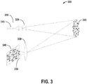
- a diagram illustrating an example Lidar 300 including both the TX and RX paths is shown.
- a vibrating fiber optic cantilever 315 may be utilized to project the scanning laser onto the target through TX optics 320.
- the free end of the fiber optic cable may travel along a spiral pattern.
- the scanning pattern used does not limit the disclosure and other scanning patterns may also be utilized.
- the laser emitting element may fire laser pulses at intervals. Each dot 325 in FIG. 3 may correspond to a single laser pulse.
- the reflected light as well as interferences is collected by the RX optics 335 onto a two-dimensional (2D) light sensor array 340 comprising a plurality of light sensors.
- the 2D light sensor array 340 may be situated at the focal plane of the RX optics 335.
- the type of the light sensors used does not limit the disclosure.
- the 2D light sensor array 340 may comprise avalanche photodiodes (APDs) or PIN photodiodes as light sensors. Shown in FIG. 3 is a 4 x 4 2D light sensor array; however, the configuration of the 2D light sensor array does not limit the disclosure.
- APDs avalanche photodiodes
- PIN photodiodes Shown in FIG. 3 is a 4 x 4 2D light sensor array; however, the configuration of the 2D light sensor array does not limit the disclosure.
- FIG. 3 it should be appreciated that although only a single lens is shown for the RX optics 335 in FIG. 3 , more complex RX optic
- the FOV of each individual light sensor in the 2D light sensor array 340 is only a fraction of the combined FOV of the whole system, the background interference collected onto each light sensor is proportionally reduced, while the reflected light useful to the Lidar is not attenuated. Therefore, the signal-to-noise ratio (SNR) value of the Lidar may be improved, increasing the range and improving the accuracy of the measurements. Moreover, the Lidar may perform more robustly in the presence of interference.
- SNR signal-to-noise ratio
- a pulsed Time of Flight (ToF) method may be utilized to measure the distance to the object being scanned.
- ToF Time of Flight
- the time when the reflected light is registered by the specific one or more light sensors in the 2D light sensor array 340 with respect to the time when the corresponding laser pulse was projected into the environment needs to be measured.
- the measurement may be performed using Time-to-Digital Converters (TDCs), or Analog-to-Digital Converters (ADCs).
- a set of predefined threshold values may be used to trigger the start and the stop of the counters, so when the voltage from a light sensor exceeds a certain value, a counter may be activated.
- the TDC has a simple architecture and is easy to implement. However, as the TDC is capable of capturing only the timing information, other data useful for the Lidar, such as the power of the reflected light, may not be captured accurately, or may be lost. Also, the TDC may not be able to correctly represent the data available in the light sensor signal when multiple objects, e.g., tree branches, rain droplets, etc., are present in the light path.
- the ADC may be better able to extract data from the light sensor signal in a comprehensive and accurate manner.
- high performance ADCs e.g., ADCs running at approximately 10GHz - may be required.
- the ADC performance requirement may be relaxed with a smaller ADC word size (e.g., 8 bits).
- the signals from the 2D light sensor array may be processed with either a parallel architecture or a serial architecture.
- each light sensor in the 2D light sensor array is provided with and connected to a dedicated time measuring converter (either a TDC or an ADC).
- a dedicated time measuring converter either a TDC or an ADC.
- the one or more particular light sensors in the 2D light sensor array that will receive the corresponding reflected light are also known.
- the accuracy of the Lidar measurements is defined by the scanning resolution on the TX path, while the RX path architecture enhances the SNR of the measurements.
- only the timing information is unknown and needs to be measured, because outputs from light sensors in the 2D light sensor array that will not receive the reflected light do not contain useful information.
- FIG. 4 a diagram illustrating an example serial architecture 400 for extracting data from a 2D light sensor array is shown. All the outputs from the individual light sensors in the 2D light sensor array 410 may be routed through a dynamic switch 420. Based on the direction of the projected laser pulse, which may be obtained from the TX path, the dynamic switch 420 may route the output from the one or more particular light sensors that are expected to receive the reflected light onto the time measuring converter(s) 430. Depending on different implementations, the number of the time measuring converter(s) 430 may vary. In one embodiment, a single time measuring converter 430 may be used. The number of the time measuring converter(s) 430 limits the number of light sensors from which signals are processed for each laser pulse firing.
- the dynamic switch 420 may correspondingly route the outputs from a new particular set of one or more light sensors to the time measuring converter(s) 430. Therefore, with the use of the dynamic switch 420, fewer time measuring converters 430 than the number of light sensors may be required. In one embodiment, only a single time measuring converter 430 is required and used.
- the 2D light sensor array may also be utilized to assist in a calibration/recalibration process of the TX path.
- the TX path may not be projecting laser pulses in the right direction.
- a calibration/recalibration process for the TX path may be performed, and tuning parameters updated.
- embodiments of the disclosure are related to a Lidar comprising a vibrating fiber optic cantilever system on the TX path and a 2D light sensor array on the RX path.
- the vibrating fiber optic cantilever system may further comprise a piezo ceramic tube and a fiber optic cable.
- the free end of the fiber optic cable may be extended outside the free end of the piezo ceramic tube by a predetermined length.
- the piezo ceramic tube may be driven by a suitable signal to vibrate at the resonant frequency of the cantilever system such that the vibration is amplified at the free end of the fiber optic cable.
- the motion of the free end of the fiber optic cable may follow a predetermined scanning pattern, and a laser emitting element may emit laser pulses at intervals.
- the laser pulses may exit from the free end of the fiber optic cable and be projected by TX optics onto the target being scanned.
- the light reflected off the target being scanned may be collected by RX optics onto the 2D light sensor array.
- a dynamic switch may route the output from one or more particular light sensors in the 2D light sensor array that are expected to receive the reflected light to one or more time measuring converters, wherein the time measuring converters may be either TDCs or ADCs. In one embodiment, only one time measuring converter may be used.
- the Lidar may process the data captured by the time measuring converters and generate a points cloud, based on which accurate 3D maps of the environment, or 3D scans of the object, may be constructed. Therefore, the accuracy of the Lidar measurements is defined by the scanning resolution on the TX path, while the RX path architecture enhances the SNR of the measurements.
- the Lidar according to the embodiments of the disclosure, may have a longer range and better signal accuracy, and may perform more robustly where interference may be present.
- Another embodiment of the disclosure is related to a method for implementing a Lidar device, comprising: implementing a vibrating fiber optic cantilever system on a transmit (TX) path; and implementing a two-dimensional (2D) light sensor array on a receive (RX) path.
- TX transmit
- RX receive
- Yet another embodiment of the disclosure is related to a non-transitory computer-readable medium comprising code which, when executed by a processor, causes the processor to implement a method comprising: driving a vibrating fiber optic cantilever system on a transmit (TX) path of a Lidar device; and driving a two-dimensional (2D) light sensor array on a receive (RX) path of the Lidar device.
- TX transmit
- RX receive
- Example methods, apparatuses, or articles of manufacture presented herein may be implemented, in whole or in part, for use in or with mobile communication devices.
- mobile device mobile communication device
- hand-held device handheld devices
- tablettes etc.
- the plural form of such terms may be used interchangeably and may refer to any kind of special purpose computing platform or device that may communicate through wireless transmission or receipt of information over suitable communications networks according to one or more communication protocols, and that may from time to time have a position or location that changes.
- special purpose mobile communication devices may include, for example, cellular telephones, satellite telephones, smart telephones, heat map or radio map generation tools or devices, observed signal parameter generation tools or devices, personal digital assistants (PDAs), laptop computers, personal entertainment systems, e-book readers, tablet personal computers (PC), personal audio or video devices, personal navigation units, wearable devices, or the like.
- PDAs personal digital assistants
- laptop computers personal entertainment systems
- e-book readers tablet personal computers
- PC tablet personal computers
- personal audio or video devices personal navigation units, wearable devices, or the like.
- a processing unit may be implemented within one or more application specific integrated circuits (ASICs), digital signal processors (DSPs), digital signal processing devices (DSPDs), programmable logic devices (PLDs), field programmable gate arrays (FPGAs), processors, controllers, micro-controllers, microprocessors, electronic devices, other devices units designed to perform the functions described herein, and/or combinations thereof.
- ASICs application specific integrated circuits
- DSPs digital signal processors
- DSPDs digital signal processing devices
- PLDs programmable logic devices
- FPGAs field programmable gate arrays
- processors controllers, micro-controllers, microprocessors, electronic devices, other devices units designed to perform the functions described herein, and/or combinations thereof.
- the herein described storage media may comprise primary, secondary, and/or tertiary storage media.
- Primary storage media may include memory such as random access memory and/or read-only memory, for example.
- Secondary storage media may include mass storage such as a magnetic or solid-state hard drive.
- Tertiary storage media may include removable storage media such as a magnetic or optical disk, a magnetic tape, a solid-state storage device, etc.
- the storage media or portions thereof may be operatively receptive of, or otherwise configurable to couple to, other components of a computing platform, such as a processor.
- one or more portions of the herein described storage media may store signals representative of data and/or information as expressed by a particular state of the storage media.
- an electronic signal representative of data and/or information may be "stored" in a portion of the storage media (e.g., memory) by affecting or changing the state of such portions of the storage media to represent data and/or information as binary information (e.g., ones and zeros).
- a change of state of the portion of the storage media to store a signal representative of data and/or information constitutes a transformation of storage media to a different state or thing.
- such quantities may take the form of electrical or magnetic signals capable of being stored, transferred, combined, compared or otherwise manipulated as electronic signals representing information. It has proven convenient at times, principally for reasons of common usage, to refer to such signals as bits, data, values, elements, symbols, characters, terms, numbers, numerals, information, or the like. It should be understood, however, that all of these or similar terms are to be associated with appropriate physical quantities and are merely convenient labels.
Landscapes
- Physics & Mathematics (AREA)
- Engineering & Computer Science (AREA)
- General Physics & Mathematics (AREA)
- Computer Networks & Wireless Communication (AREA)
- Radar, Positioning & Navigation (AREA)
- Remote Sensing (AREA)
- Electromagnetism (AREA)
- Optics & Photonics (AREA)
- Optical Radar Systems And Details Thereof (AREA)
- Measurement Of Optical Distance (AREA)
- Mechanical Optical Scanning Systems (AREA)
- Optical Couplings Of Light Guides (AREA)
Applications Claiming Priority (3)
| Application Number | Priority Date | Filing Date | Title |
|---|---|---|---|
| US201562220777P | 2015-09-18 | 2015-09-18 | |
| US15/266,618 US10408926B2 (en) | 2015-09-18 | 2016-09-15 | Implementation of the focal plane 2D APD array for hyperion lidar system |
| PCT/US2016/052244 WO2017049154A1 (en) | 2015-09-18 | 2016-09-16 | Implementation of the focal plane 2d apd array for hyperion lidar system |
Publications (2)
| Publication Number | Publication Date |
|---|---|
| EP3350614A1 EP3350614A1 (en) | 2018-07-25 |
| EP3350614B1 true EP3350614B1 (en) | 2020-08-12 |
Family
ID=57043008
Family Applications (1)
| Application Number | Title | Priority Date | Filing Date |
|---|---|---|---|
| EP16774759.1A Active EP3350614B1 (en) | 2015-09-18 | 2016-09-16 | Implementation of the focal plane 2d apd array for hyperion lidar system |
Country Status (7)
| Country | Link |
|---|---|
| US (2) | US10408926B2 (ja) |
| EP (1) | EP3350614B1 (ja) |
| JP (1) | JP6688880B2 (ja) |
| KR (1) | KR102114781B1 (ja) |
| CN (2) | CN108027424B (ja) |
| BR (1) | BR112018005427B1 (ja) |
| WO (1) | WO2017049154A1 (ja) |
Families Citing this family (5)
| Publication number | Priority date | Publication date | Assignee | Title |
|---|---|---|---|---|
| US10408926B2 (en) | 2015-09-18 | 2019-09-10 | Qualcomm Incorporated | Implementation of the focal plane 2D APD array for hyperion lidar system |
| US10509113B2 (en) * | 2017-04-07 | 2019-12-17 | ActLight SA | Techniques for performing time of flight measurements |
| JP7273565B2 (ja) | 2019-03-19 | 2023-05-15 | 株式会社東芝 | 受光装置及び距離測定装置 |
| US11556000B1 (en) | 2019-08-22 | 2023-01-17 | Red Creamery Llc | Distally-actuated scanning mirror |
| CN111308497A (zh) * | 2020-03-06 | 2020-06-19 | 深圳市方腾网络技术有限公司 | 一种3d激光雷达及激光雷达实现方法 |
Family Cites Families (37)
| Publication number | Priority date | Publication date | Assignee | Title |
|---|---|---|---|---|
| US5157257A (en) * | 1990-06-18 | 1992-10-20 | Lasen, Inc. | Mid-infrared light hydrocarbon DIAL LIDAR |
| US5317148A (en) | 1991-05-22 | 1994-05-31 | Loral Corporation | IR/ladar scanner |
| JP3697319B2 (ja) | 1996-06-14 | 2005-09-21 | 株式会社日立コミュニケーションテクノロジー | 光伝送装置および光ネットワーク |
| US6341118B1 (en) * | 1998-06-02 | 2002-01-22 | Science Applications International Corporation | Multiple channel scanning device using oversampling and image processing to increase throughput |
| JP3832101B2 (ja) * | 1998-08-05 | 2006-10-11 | 株式会社デンソー | 距離測定装置 |
| US6563105B2 (en) | 1999-06-08 | 2003-05-13 | University Of Washington | Image acquisition with depth enhancement |
| JP2002039716A (ja) * | 2000-07-25 | 2002-02-06 | Olympus Optical Co Ltd | 距離画像入力装置 |
| US20020092340A1 (en) * | 2000-10-30 | 2002-07-18 | Veeco Instruments Inc. | Cantilever array sensor system |
| US6433543B1 (en) * | 2002-01-04 | 2002-08-13 | Mohsen Shahinpoor | Smart fiber optic magnetometer |
| US6936810B2 (en) * | 2003-07-21 | 2005-08-30 | Thomas Hiramatsu-Tie | Method and apparatus for scanning an optical beam using an optical conduit |
| US7064817B1 (en) | 2003-11-04 | 2006-06-20 | Sandia Corporation | Method to determine and adjust the alignment of the transmitter and receiver fields of view of a LIDAR system |
| US7236235B2 (en) * | 2004-07-06 | 2007-06-26 | Dimsdale Engineering, Llc | System and method for determining range in 3D imaging systems |
| WO2007024221A1 (en) | 2005-08-23 | 2007-03-01 | University Of Washington | Distance determination in a scanned beam image capture device |
| US7312879B2 (en) * | 2005-08-23 | 2007-12-25 | University Of Washington | Distance determination in a scanned beam image capture device |
| WO2007067163A1 (en) * | 2005-11-23 | 2007-06-14 | University Of Washington | Scanning beam with variable sequential framing using interrupted scanning resonance |
| US8437587B2 (en) * | 2007-07-25 | 2013-05-07 | University Of Washington | Actuating an optical fiber with a piezoelectric actuator and detecting voltages generated by the piezoelectric actuator |
| JP5144185B2 (ja) * | 2007-09-13 | 2013-02-13 | 株式会社エヌ・ティ・ティ・ドコモ | 情報検索システム及び情報検索方法 |
| CA2710212C (en) | 2007-12-21 | 2014-12-09 | Leddartech Inc. | Detection and ranging methods and systems |
| FI20095619A0 (fi) * | 2009-06-04 | 2009-06-04 | Gasera Ltd | Järjestelmä ja menetelmä suhteellisen liikkeen mittaamiseksi |
| JP2012083267A (ja) * | 2010-10-13 | 2012-04-26 | Japan Aerospace Exploration Agency | マルチライダーシステム |
| US8946637B2 (en) | 2010-11-23 | 2015-02-03 | The United States Of America As Represented By The Secretary Of The Army | Compact fiber-based scanning laser detection and ranging system |
| EP2469295A1 (en) | 2010-12-23 | 2012-06-27 | André Borowski | 3D landscape real-time imager and corresponding imaging methods |
| CN103502839B (zh) * | 2011-03-17 | 2016-06-15 | 加泰罗尼亚科技大学 | 用于接收光束的系统、方法和计算机程序 |
| US9069061B1 (en) * | 2011-07-19 | 2015-06-30 | Ball Aerospace & Technologies Corp. | LIDAR with analog memory |
| US8826188B2 (en) | 2011-08-26 | 2014-09-02 | Qualcomm Incorporated | Proximity sensor calibration |
| US8797512B2 (en) | 2011-09-15 | 2014-08-05 | Advanced Scientific Concepts, Inc. | Automatic range corrected flash ladar camera |
| CN102525384B (zh) * | 2011-12-23 | 2014-06-18 | 华中科技大学 | 光纤悬臂共振型扫描器的二维栅格式扫描方法 |
| US9323010B2 (en) * | 2012-01-10 | 2016-04-26 | Invensas Corporation | Structures formed using monocrystalline silicon and/or other materials for optical and other applications |
| US9448110B2 (en) * | 2012-09-27 | 2016-09-20 | Northrop Grumman Systems Corporation | Three-dimensional hyperspectral imaging systems and methods using a light detection and ranging (LIDAR) focal plane array |
| DE202013101039U1 (de) | 2013-03-11 | 2014-03-12 | Sick Ag | Optoelektronischer Sensor zur Entfernungsmessung |
| CN103412313B (zh) * | 2013-07-30 | 2015-03-25 | 桂林理工大学 | 低空轻小型面阵激光雷达测量系统 |
| CN203385859U (zh) * | 2013-07-30 | 2014-01-08 | 桂林理工大学 | 一种面阵激光雷达测量装置 |
| TWI543751B (zh) * | 2013-12-20 | 2016-08-01 | 緯創資通股份有限公司 | 高度量測裝置及其方法 |
| CN103744087B (zh) * | 2014-01-11 | 2016-03-02 | 桂林理工大学 | 一种脉冲式n×n阵列激光雷达系统 |
| US10379222B2 (en) * | 2014-07-04 | 2019-08-13 | Z-Senz Llc | Systems, devices, and/or methods for resonant light ranging and distance sensing |
| KR20230042386A (ko) * | 2014-08-15 | 2023-03-28 | 에이아이, 아이엔씨. | 레이더 전송을 위한 방법 및 시스템 |
| US10408926B2 (en) | 2015-09-18 | 2019-09-10 | Qualcomm Incorporated | Implementation of the focal plane 2D APD array for hyperion lidar system |
-
2016
- 2016-09-15 US US15/266,618 patent/US10408926B2/en active Active
- 2016-09-16 KR KR1020187010376A patent/KR102114781B1/ko active IP Right Grant
- 2016-09-16 CN CN201680053168.6A patent/CN108027424B/zh active Active
- 2016-09-16 EP EP16774759.1A patent/EP3350614B1/en active Active
- 2016-09-16 BR BR112018005427-5A patent/BR112018005427B1/pt active IP Right Grant
- 2016-09-16 CN CN202210529710.8A patent/CN115166688A/zh active Pending
- 2016-09-16 JP JP2018513367A patent/JP6688880B2/ja active Active
- 2016-09-16 WO PCT/US2016/052244 patent/WO2017049154A1/en active Application Filing
-
2019
- 2019-08-30 US US16/557,537 patent/US11846730B2/en active Active
Non-Patent Citations (1)
| Title |
|---|
| None * |
Also Published As
| Publication number | Publication date |
|---|---|
| US20200011975A1 (en) | 2020-01-09 |
| BR112018005427B1 (pt) | 2023-11-21 |
| KR20180054691A (ko) | 2018-05-24 |
| CN108027424B (zh) | 2022-05-10 |
| EP3350614A1 (en) | 2018-07-25 |
| JP6688880B2 (ja) | 2020-04-28 |
| US11846730B2 (en) | 2023-12-19 |
| US10408926B2 (en) | 2019-09-10 |
| KR102114781B1 (ko) | 2020-05-25 |
| CN115166688A (zh) | 2022-10-11 |
| WO2017049154A1 (en) | 2017-03-23 |
| JP2018536144A (ja) | 2018-12-06 |
| BR112018005427A2 (ja) | 2018-10-02 |
| CN108027424A (zh) | 2018-05-11 |
| US20170212223A1 (en) | 2017-07-27 |
Similar Documents
| Publication | Publication Date | Title |
|---|---|---|
| US11846730B2 (en) | Implementation of the focal plane 2D APD array for hyperion Lidar system | |
| CN109196378B (zh) | 用于遥感接收器的光学系统 | |
| US11723762B2 (en) | LIDAR based 3-D imaging with far-field illumination overlap | |
| EP2453253B1 (en) | A multi-directional active sensor system and a method for sensing electromagnetic radiation | |
| US20180059221A1 (en) | Hybrid scanning lidar systems | |
| CN109564276A (zh) | 用于在光学系统中测量参考及返回光束的系统及方法 | |
| US9981604B2 (en) | Object detector and sensing apparatus | |
| EP3791209B1 (en) | Phase wrapping determination for time-of-flight camera | |
| US11237256B2 (en) | Methods and systems for dithering active sensor pulse emissions | |
| WO2017038659A1 (ja) | 運動検出装置及びそれを用いた三次元形状測定装置 | |
| CN111337933A (zh) | 光检测和测距设备及其驱动方法 | |
| US11879979B2 (en) | Method and apparatus for dynamic reconfiguration of region of interest in integrated FMCW LIDAR | |
| CN112105944A (zh) | 具有使用短脉冲和长脉冲的多模式操作的光学测距系统 | |
| WO2022056145A1 (en) | Apparatus and methods for long range, high resolution lidar | |
| US20220350000A1 (en) | Lidar systems for near-field and far-field detection, and related methods and apparatus | |
| US20230194684A1 (en) | Blockage detection methods for lidar systems and devices based on passive channel listening | |
| US20220283273A1 (en) | Scanning fiber transmitter for distance detection | |
| WO2022216531A9 (en) | High-range, low-power lidar systems, and related methods and apparatus | |
| Shojaeipour et al. | Laser-pointer rangefinder between mobile robot and obstacles via webcam based | |
| Zhou et al. | 3D flash LiDAR imager onboard UAV | |
| Zhang et al. | A method for pulsed scannerless laser imaging using focal plane array | |
| KR20200050008A (ko) | 3차원 공간 스캐닝 기술을 활용한 라이다 장치 | |
| Tan et al. | Reach on laser imaging technology to terminal guidance |
Legal Events
| Date | Code | Title | Description |
|---|---|---|---|
| STAA | Information on the status of an ep patent application or granted ep patent |
Free format text: STATUS: THE INTERNATIONAL PUBLICATION HAS BEEN MADE |
|
| PUAI | Public reference made under article 153(3) epc to a published international application that has entered the european phase |
Free format text: ORIGINAL CODE: 0009012 |
|
| STAA | Information on the status of an ep patent application or granted ep patent |
Free format text: STATUS: REQUEST FOR EXAMINATION WAS MADE |
|
| 17P | Request for examination filed |
Effective date: 20180411 |
|
| AK | Designated contracting states |
Kind code of ref document: A1 Designated state(s): AL AT BE BG CH CY CZ DE DK EE ES FI FR GB GR HR HU IE IS IT LI LT LU LV MC MK MT NL NO PL PT RO RS SE SI SK SM TR |
|
| AX | Request for extension of the european patent |
Extension state: BA ME |
|
| DAV | Request for validation of the european patent (deleted) | ||
| DAX | Request for extension of the european patent (deleted) | ||
| GRAP | Despatch of communication of intention to grant a patent |
Free format text: ORIGINAL CODE: EPIDOSNIGR1 |
|
| STAA | Information on the status of an ep patent application or granted ep patent |
Free format text: STATUS: GRANT OF PATENT IS INTENDED |
|
| INTG | Intention to grant announced |
Effective date: 20200312 |
|
| GRAS | Grant fee paid |
Free format text: ORIGINAL CODE: EPIDOSNIGR3 |
|
| GRAA | (expected) grant |
Free format text: ORIGINAL CODE: 0009210 |
|
| STAA | Information on the status of an ep patent application or granted ep patent |
Free format text: STATUS: THE PATENT HAS BEEN GRANTED |
|
| AK | Designated contracting states |
Kind code of ref document: B1 Designated state(s): AL AT BE BG CH CY CZ DE DK EE ES FI FR GB GR HR HU IE IS IT LI LT LU LV MC MK MT NL NO PL PT RO RS SE SI SK SM TR |
|
| REG | Reference to a national code |
Ref country code: CH Ref legal event code: EP |
|
| REG | Reference to a national code |
Ref country code: DE Ref legal event code: R096 Ref document number: 602016041907 Country of ref document: DE |
|
| REG | Reference to a national code |
Ref country code: IE Ref legal event code: FG4D |
|
| REG | Reference to a national code |
Ref country code: AT Ref legal event code: REF Ref document number: 1302095 Country of ref document: AT Kind code of ref document: T Effective date: 20200915 |
|
| REG | Reference to a national code |
Ref country code: DE Ref legal event code: R082 Ref document number: 602016041907 Country of ref document: DE Representative=s name: WAGNER & GEYER PARTNERSCHAFT MBB PATENT- UND R, DE |
|
| REG | Reference to a national code |
Ref country code: LT Ref legal event code: MG4D |
|
| REG | Reference to a national code |
Ref country code: NL Ref legal event code: MP Effective date: 20200812 |
|
| PG25 | Lapsed in a contracting state [announced via postgrant information from national office to epo] |
Ref country code: SE Free format text: LAPSE BECAUSE OF FAILURE TO SUBMIT A TRANSLATION OF THE DESCRIPTION OR TO PAY THE FEE WITHIN THE PRESCRIBED TIME-LIMIT Effective date: 20200812 Ref country code: BG Free format text: LAPSE BECAUSE OF FAILURE TO SUBMIT A TRANSLATION OF THE DESCRIPTION OR TO PAY THE FEE WITHIN THE PRESCRIBED TIME-LIMIT Effective date: 20201112 Ref country code: HR Free format text: LAPSE BECAUSE OF FAILURE TO SUBMIT A TRANSLATION OF THE DESCRIPTION OR TO PAY THE FEE WITHIN THE PRESCRIBED TIME-LIMIT Effective date: 20200812 Ref country code: GR Free format text: LAPSE BECAUSE OF FAILURE TO SUBMIT A TRANSLATION OF THE DESCRIPTION OR TO PAY THE FEE WITHIN THE PRESCRIBED TIME-LIMIT Effective date: 20201113 Ref country code: NO Free format text: LAPSE BECAUSE OF FAILURE TO SUBMIT A TRANSLATION OF THE DESCRIPTION OR TO PAY THE FEE WITHIN THE PRESCRIBED TIME-LIMIT Effective date: 20201112 Ref country code: LT Free format text: LAPSE BECAUSE OF FAILURE TO SUBMIT A TRANSLATION OF THE DESCRIPTION OR TO PAY THE FEE WITHIN THE PRESCRIBED TIME-LIMIT Effective date: 20200812 Ref country code: FI Free format text: LAPSE BECAUSE OF FAILURE TO SUBMIT A TRANSLATION OF THE DESCRIPTION OR TO PAY THE FEE WITHIN THE PRESCRIBED TIME-LIMIT Effective date: 20200812 |
|
| REG | Reference to a national code |
Ref country code: AT Ref legal event code: MK05 Ref document number: 1302095 Country of ref document: AT Kind code of ref document: T Effective date: 20200812 |
|
| PG25 | Lapsed in a contracting state [announced via postgrant information from national office to epo] |
Ref country code: LV Free format text: LAPSE BECAUSE OF FAILURE TO SUBMIT A TRANSLATION OF THE DESCRIPTION OR TO PAY THE FEE WITHIN THE PRESCRIBED TIME-LIMIT Effective date: 20200812 Ref country code: RS Free format text: LAPSE BECAUSE OF FAILURE TO SUBMIT A TRANSLATION OF THE DESCRIPTION OR TO PAY THE FEE WITHIN THE PRESCRIBED TIME-LIMIT Effective date: 20200812 Ref country code: PL Free format text: LAPSE BECAUSE OF FAILURE TO SUBMIT A TRANSLATION OF THE DESCRIPTION OR TO PAY THE FEE WITHIN THE PRESCRIBED TIME-LIMIT Effective date: 20200812 Ref country code: NL Free format text: LAPSE BECAUSE OF FAILURE TO SUBMIT A TRANSLATION OF THE DESCRIPTION OR TO PAY THE FEE WITHIN THE PRESCRIBED TIME-LIMIT Effective date: 20200812 Ref country code: IS Free format text: LAPSE BECAUSE OF FAILURE TO SUBMIT A TRANSLATION OF THE DESCRIPTION OR TO PAY THE FEE WITHIN THE PRESCRIBED TIME-LIMIT Effective date: 20201212 |
|
| PG25 | Lapsed in a contracting state [announced via postgrant information from national office to epo] |
Ref country code: EE Free format text: LAPSE BECAUSE OF FAILURE TO SUBMIT A TRANSLATION OF THE DESCRIPTION OR TO PAY THE FEE WITHIN THE PRESCRIBED TIME-LIMIT Effective date: 20200812 Ref country code: SM Free format text: LAPSE BECAUSE OF FAILURE TO SUBMIT A TRANSLATION OF THE DESCRIPTION OR TO PAY THE FEE WITHIN THE PRESCRIBED TIME-LIMIT Effective date: 20200812 Ref country code: RO Free format text: LAPSE BECAUSE OF FAILURE TO SUBMIT A TRANSLATION OF THE DESCRIPTION OR TO PAY THE FEE WITHIN THE PRESCRIBED TIME-LIMIT Effective date: 20200812 Ref country code: CZ Free format text: LAPSE BECAUSE OF FAILURE TO SUBMIT A TRANSLATION OF THE DESCRIPTION OR TO PAY THE FEE WITHIN THE PRESCRIBED TIME-LIMIT Effective date: 20200812 Ref country code: DK Free format text: LAPSE BECAUSE OF FAILURE TO SUBMIT A TRANSLATION OF THE DESCRIPTION OR TO PAY THE FEE WITHIN THE PRESCRIBED TIME-LIMIT Effective date: 20200812 |
|
| REG | Reference to a national code |
Ref country code: CH Ref legal event code: PL |
|
| REG | Reference to a national code |
Ref country code: DE Ref legal event code: R097 Ref document number: 602016041907 Country of ref document: DE |
|
| PG25 | Lapsed in a contracting state [announced via postgrant information from national office to epo] |
Ref country code: MC Free format text: LAPSE BECAUSE OF FAILURE TO SUBMIT A TRANSLATION OF THE DESCRIPTION OR TO PAY THE FEE WITHIN THE PRESCRIBED TIME-LIMIT Effective date: 20200812 Ref country code: ES Free format text: LAPSE BECAUSE OF FAILURE TO SUBMIT A TRANSLATION OF THE DESCRIPTION OR TO PAY THE FEE WITHIN THE PRESCRIBED TIME-LIMIT Effective date: 20200812 Ref country code: AL Free format text: LAPSE BECAUSE OF FAILURE TO SUBMIT A TRANSLATION OF THE DESCRIPTION OR TO PAY THE FEE WITHIN THE PRESCRIBED TIME-LIMIT Effective date: 20200812 Ref country code: AT Free format text: LAPSE BECAUSE OF FAILURE TO SUBMIT A TRANSLATION OF THE DESCRIPTION OR TO PAY THE FEE WITHIN THE PRESCRIBED TIME-LIMIT Effective date: 20200812 |
|
| PLBE | No opposition filed within time limit |
Free format text: ORIGINAL CODE: 0009261 |
|
| REG | Reference to a national code |
Ref country code: BE Ref legal event code: MM Effective date: 20200930 |
|
| STAA | Information on the status of an ep patent application or granted ep patent |
Free format text: STATUS: NO OPPOSITION FILED WITHIN TIME LIMIT |
|
| PG25 | Lapsed in a contracting state [announced via postgrant information from national office to epo] |
Ref country code: LU Free format text: LAPSE BECAUSE OF NON-PAYMENT OF DUE FEES Effective date: 20200916 Ref country code: SK Free format text: LAPSE BECAUSE OF FAILURE TO SUBMIT A TRANSLATION OF THE DESCRIPTION OR TO PAY THE FEE WITHIN THE PRESCRIBED TIME-LIMIT Effective date: 20200812 |
|
| 26N | No opposition filed |
Effective date: 20210514 |
|
| PG25 | Lapsed in a contracting state [announced via postgrant information from national office to epo] |
Ref country code: IT Free format text: LAPSE BECAUSE OF FAILURE TO SUBMIT A TRANSLATION OF THE DESCRIPTION OR TO PAY THE FEE WITHIN THE PRESCRIBED TIME-LIMIT Effective date: 20200812 |
|
| PG25 | Lapsed in a contracting state [announced via postgrant information from national office to epo] |
Ref country code: CH Free format text: LAPSE BECAUSE OF NON-PAYMENT OF DUE FEES Effective date: 20200930 Ref country code: BE Free format text: LAPSE BECAUSE OF NON-PAYMENT OF DUE FEES Effective date: 20200930 Ref country code: LI Free format text: LAPSE BECAUSE OF NON-PAYMENT OF DUE FEES Effective date: 20200930 Ref country code: IE Free format text: LAPSE BECAUSE OF NON-PAYMENT OF DUE FEES Effective date: 20200916 Ref country code: SI Free format text: LAPSE BECAUSE OF FAILURE TO SUBMIT A TRANSLATION OF THE DESCRIPTION OR TO PAY THE FEE WITHIN THE PRESCRIBED TIME-LIMIT Effective date: 20200812 |
|
| PG25 | Lapsed in a contracting state [announced via postgrant information from national office to epo] |
Ref country code: TR Free format text: LAPSE BECAUSE OF FAILURE TO SUBMIT A TRANSLATION OF THE DESCRIPTION OR TO PAY THE FEE WITHIN THE PRESCRIBED TIME-LIMIT Effective date: 20200812 Ref country code: MT Free format text: LAPSE BECAUSE OF FAILURE TO SUBMIT A TRANSLATION OF THE DESCRIPTION OR TO PAY THE FEE WITHIN THE PRESCRIBED TIME-LIMIT Effective date: 20200812 Ref country code: CY Free format text: LAPSE BECAUSE OF FAILURE TO SUBMIT A TRANSLATION OF THE DESCRIPTION OR TO PAY THE FEE WITHIN THE PRESCRIBED TIME-LIMIT Effective date: 20200812 |
|
| PG25 | Lapsed in a contracting state [announced via postgrant information from national office to epo] |
Ref country code: MK Free format text: LAPSE BECAUSE OF FAILURE TO SUBMIT A TRANSLATION OF THE DESCRIPTION OR TO PAY THE FEE WITHIN THE PRESCRIBED TIME-LIMIT Effective date: 20200812 |
|
| PG25 | Lapsed in a contracting state [announced via postgrant information from national office to epo] |
Ref country code: PT Free format text: LAPSE BECAUSE OF FAILURE TO SUBMIT A TRANSLATION OF THE DESCRIPTION OR TO PAY THE FEE WITHIN THE PRESCRIBED TIME-LIMIT Effective date: 20200812 |
|
| PGFP | Annual fee paid to national office [announced via postgrant information from national office to epo] |
Ref country code: GB Payment date: 20230810 Year of fee payment: 8 |
|
| PGFP | Annual fee paid to national office [announced via postgrant information from national office to epo] |
Ref country code: FR Payment date: 20230808 Year of fee payment: 8 Ref country code: DE Payment date: 20230808 Year of fee payment: 8 |