EP3349687B1 - Vorrichtungen zur durchführung perkutaner glenn- und fontan-eingriffe - Google Patents
Vorrichtungen zur durchführung perkutaner glenn- und fontan-eingriffe Download PDFInfo
- Publication number
- EP3349687B1 EP3349687B1 EP16847336.1A EP16847336A EP3349687B1 EP 3349687 B1 EP3349687 B1 EP 3349687B1 EP 16847336 A EP16847336 A EP 16847336A EP 3349687 B1 EP3349687 B1 EP 3349687B1
- Authority
- EP
- European Patent Office
- Prior art keywords
- prosthesis
- delivery system
- distal
- segment
- markers
- Prior art date
- Legal status (The legal status is an assumption and is not a legal conclusion. Google has not performed a legal analysis and makes no representation as to the accuracy of the status listed.)
- Active
Links
- 238000000034 method Methods 0.000 title claims description 35
- 239000004744 fabric Substances 0.000 claims description 9
- UQSXHKLRYXJYBZ-UHFFFAOYSA-N Iron oxide Chemical compound [Fe]=O UQSXHKLRYXJYBZ-UHFFFAOYSA-N 0.000 claims description 4
- 210000001124 body fluid Anatomy 0.000 claims description 2
- 238000003384 imaging method Methods 0.000 claims description 2
- 210000002620 vena cava superior Anatomy 0.000 description 9
- 239000007943 implant Substances 0.000 description 8
- 210000001147 pulmonary artery Anatomy 0.000 description 8
- 238000001356 surgical procedure Methods 0.000 description 6
- 230000002526 effect on cardiovascular system Effects 0.000 description 5
- 210000000056 organ Anatomy 0.000 description 4
- 208000002330 Congenital Heart Defects Diseases 0.000 description 3
- 230000003872 anastomosis Effects 0.000 description 3
- 208000028831 congenital heart disease Diseases 0.000 description 3
- 230000007704 transition Effects 0.000 description 3
- 206010010356 Congenital anomaly Diseases 0.000 description 2
- 206010019280 Heart failures Diseases 0.000 description 2
- 206010045545 Univentricular heart Diseases 0.000 description 2
- 210000000709 aorta Anatomy 0.000 description 2
- 238000013459 approach Methods 0.000 description 2
- 239000003550 marker Substances 0.000 description 2
- 239000000463 material Substances 0.000 description 2
- 238000011499 palliative surgery Methods 0.000 description 2
- 230000002685 pulmonary effect Effects 0.000 description 2
- 238000002054 transplantation Methods 0.000 description 2
- 210000001631 vena cava inferior Anatomy 0.000 description 2
- 206010011703 Cyanosis Diseases 0.000 description 1
- 230000001154 acute effect Effects 0.000 description 1
- 238000010171 animal model Methods 0.000 description 1
- 210000002376 aorta thoracic Anatomy 0.000 description 1
- 210000001367 artery Anatomy 0.000 description 1
- 230000002457 bidirectional effect Effects 0.000 description 1
- 239000008280 blood Substances 0.000 description 1
- 210000004369 blood Anatomy 0.000 description 1
- 230000017531 blood circulation Effects 0.000 description 1
- 210000004204 blood vessel Anatomy 0.000 description 1
- 230000006835 compression Effects 0.000 description 1
- 238000007906 compression Methods 0.000 description 1
- 238000013461 design Methods 0.000 description 1
- 238000006073 displacement reaction Methods 0.000 description 1
- 239000003814 drug Substances 0.000 description 1
- 229940079593 drug Drugs 0.000 description 1
- 238000002594 fluoroscopy Methods 0.000 description 1
- 238000007373 indentation Methods 0.000 description 1
- 238000007726 management method Methods 0.000 description 1
- 229910001000 nickel titanium Inorganic materials 0.000 description 1
- 230000035479 physiological effects, processes and functions Effects 0.000 description 1
- 229920000728 polyester Polymers 0.000 description 1
- 210000005245 right atrium Anatomy 0.000 description 1
- 238000009958 sewing Methods 0.000 description 1
- 230000006641 stabilisation Effects 0.000 description 1
- 238000011105 stabilization Methods 0.000 description 1
- 230000009885 systemic effect Effects 0.000 description 1
- 238000012360 testing method Methods 0.000 description 1
- 230000000472 traumatic effect Effects 0.000 description 1
- 210000005166 vasculature Anatomy 0.000 description 1
- 238000012800 visualization Methods 0.000 description 1
- 238000004804 winding Methods 0.000 description 1
Images


Classifications
-
- A—HUMAN NECESSITIES
- A61—MEDICAL OR VETERINARY SCIENCE; HYGIENE
- A61B—DIAGNOSIS; SURGERY; IDENTIFICATION
- A61B17/00—Surgical instruments, devices or methods, e.g. tourniquets
- A61B17/11—Surgical instruments, devices or methods, e.g. tourniquets for performing anastomosis; Buttons for anastomosis
-
- A—HUMAN NECESSITIES
- A61—MEDICAL OR VETERINARY SCIENCE; HYGIENE
- A61F—FILTERS IMPLANTABLE INTO BLOOD VESSELS; PROSTHESES; DEVICES PROVIDING PATENCY TO, OR PREVENTING COLLAPSING OF, TUBULAR STRUCTURES OF THE BODY, e.g. STENTS; ORTHOPAEDIC, NURSING OR CONTRACEPTIVE DEVICES; FOMENTATION; TREATMENT OR PROTECTION OF EYES OR EARS; BANDAGES, DRESSINGS OR ABSORBENT PADS; FIRST-AID KITS
- A61F2/00—Filters implantable into blood vessels; Prostheses, i.e. artificial substitutes or replacements for parts of the body; Appliances for connecting them with the body; Devices providing patency to, or preventing collapsing of, tubular structures of the body, e.g. stents
- A61F2/02—Prostheses implantable into the body
- A61F2/04—Hollow or tubular parts of organs, e.g. bladders, tracheae, bronchi or bile ducts
- A61F2/06—Blood vessels
- A61F2/064—Blood vessels with special features to facilitate anastomotic coupling
-
- A—HUMAN NECESSITIES
- A61—MEDICAL OR VETERINARY SCIENCE; HYGIENE
- A61M—DEVICES FOR INTRODUCING MEDIA INTO, OR ONTO, THE BODY; DEVICES FOR TRANSDUCING BODY MEDIA OR FOR TAKING MEDIA FROM THE BODY; DEVICES FOR PRODUCING OR ENDING SLEEP OR STUPOR
- A61M25/00—Catheters; Hollow probes
-
- A—HUMAN NECESSITIES
- A61—MEDICAL OR VETERINARY SCIENCE; HYGIENE
- A61B—DIAGNOSIS; SURGERY; IDENTIFICATION
- A61B17/00—Surgical instruments, devices or methods, e.g. tourniquets
- A61B17/00234—Surgical instruments, devices or methods, e.g. tourniquets for minimally invasive surgery
- A61B2017/00238—Type of minimally invasive operation
- A61B2017/00243—Type of minimally invasive operation cardiac
- A61B2017/00247—Making holes in the wall of the heart, e.g. laser Myocardial revascularization
- A61B2017/00252—Making holes in the wall of the heart, e.g. laser Myocardial revascularization for by-pass connections, i.e. connections from heart chamber to blood vessel or from blood vessel to blood vessel
-
- A—HUMAN NECESSITIES
- A61—MEDICAL OR VETERINARY SCIENCE; HYGIENE
- A61B—DIAGNOSIS; SURGERY; IDENTIFICATION
- A61B17/00—Surgical instruments, devices or methods, e.g. tourniquets
- A61B17/11—Surgical instruments, devices or methods, e.g. tourniquets for performing anastomosis; Buttons for anastomosis
- A61B2017/1107—Surgical instruments, devices or methods, e.g. tourniquets for performing anastomosis; Buttons for anastomosis for blood vessels
-
- A—HUMAN NECESSITIES
- A61—MEDICAL OR VETERINARY SCIENCE; HYGIENE
- A61B—DIAGNOSIS; SURGERY; IDENTIFICATION
- A61B17/00—Surgical instruments, devices or methods, e.g. tourniquets
- A61B17/11—Surgical instruments, devices or methods, e.g. tourniquets for performing anastomosis; Buttons for anastomosis
- A61B2017/1139—Side-to-side connections, e.g. shunt or X-connections
-
- A—HUMAN NECESSITIES
- A61—MEDICAL OR VETERINARY SCIENCE; HYGIENE
- A61F—FILTERS IMPLANTABLE INTO BLOOD VESSELS; PROSTHESES; DEVICES PROVIDING PATENCY TO, OR PREVENTING COLLAPSING OF, TUBULAR STRUCTURES OF THE BODY, e.g. STENTS; ORTHOPAEDIC, NURSING OR CONTRACEPTIVE DEVICES; FOMENTATION; TREATMENT OR PROTECTION OF EYES OR EARS; BANDAGES, DRESSINGS OR ABSORBENT PADS; FIRST-AID KITS
- A61F2/00—Filters implantable into blood vessels; Prostheses, i.e. artificial substitutes or replacements for parts of the body; Appliances for connecting them with the body; Devices providing patency to, or preventing collapsing of, tubular structures of the body, e.g. stents
- A61F2/02—Prostheses implantable into the body
- A61F2/04—Hollow or tubular parts of organs, e.g. bladders, tracheae, bronchi or bile ducts
- A61F2/06—Blood vessels
- A61F2/07—Stent-grafts
-
- A—HUMAN NECESSITIES
- A61—MEDICAL OR VETERINARY SCIENCE; HYGIENE
- A61F—FILTERS IMPLANTABLE INTO BLOOD VESSELS; PROSTHESES; DEVICES PROVIDING PATENCY TO, OR PREVENTING COLLAPSING OF, TUBULAR STRUCTURES OF THE BODY, e.g. STENTS; ORTHOPAEDIC, NURSING OR CONTRACEPTIVE DEVICES; FOMENTATION; TREATMENT OR PROTECTION OF EYES OR EARS; BANDAGES, DRESSINGS OR ABSORBENT PADS; FIRST-AID KITS
- A61F2/00—Filters implantable into blood vessels; Prostheses, i.e. artificial substitutes or replacements for parts of the body; Appliances for connecting them with the body; Devices providing patency to, or preventing collapsing of, tubular structures of the body, e.g. stents
- A61F2/82—Devices providing patency to, or preventing collapsing of, tubular structures of the body, e.g. stents
- A61F2002/828—Means for connecting a plurality of stents allowing flexibility of the whole structure
-
- A—HUMAN NECESSITIES
- A61—MEDICAL OR VETERINARY SCIENCE; HYGIENE
- A61F—FILTERS IMPLANTABLE INTO BLOOD VESSELS; PROSTHESES; DEVICES PROVIDING PATENCY TO, OR PREVENTING COLLAPSING OF, TUBULAR STRUCTURES OF THE BODY, e.g. STENTS; ORTHOPAEDIC, NURSING OR CONTRACEPTIVE DEVICES; FOMENTATION; TREATMENT OR PROTECTION OF EYES OR EARS; BANDAGES, DRESSINGS OR ABSORBENT PADS; FIRST-AID KITS
- A61F2/00—Filters implantable into blood vessels; Prostheses, i.e. artificial substitutes or replacements for parts of the body; Appliances for connecting them with the body; Devices providing patency to, or preventing collapsing of, tubular structures of the body, e.g. stents
- A61F2/82—Devices providing patency to, or preventing collapsing of, tubular structures of the body, e.g. stents
- A61F2/86—Stents in a form characterised by the wire-like elements; Stents in the form characterised by a net-like or mesh-like structure
- A61F2/90—Stents in a form characterised by the wire-like elements; Stents in the form characterised by a net-like or mesh-like structure characterised by a net-like or mesh-like structure
- A61F2/91—Stents in a form characterised by the wire-like elements; Stents in the form characterised by a net-like or mesh-like structure characterised by a net-like or mesh-like structure made from perforated sheet material or tubes, e.g. perforated by laser cuts or etched holes
- A61F2/915—Stents in a form characterised by the wire-like elements; Stents in the form characterised by a net-like or mesh-like structure characterised by a net-like or mesh-like structure made from perforated sheet material or tubes, e.g. perforated by laser cuts or etched holes with bands having a meander structure, adjacent bands being connected to each other
- A61F2002/9155—Adjacent bands being connected to each other
- A61F2002/91575—Adjacent bands being connected to each other connected peak to trough
-
- A—HUMAN NECESSITIES
- A61—MEDICAL OR VETERINARY SCIENCE; HYGIENE
- A61F—FILTERS IMPLANTABLE INTO BLOOD VESSELS; PROSTHESES; DEVICES PROVIDING PATENCY TO, OR PREVENTING COLLAPSING OF, TUBULAR STRUCTURES OF THE BODY, e.g. STENTS; ORTHOPAEDIC, NURSING OR CONTRACEPTIVE DEVICES; FOMENTATION; TREATMENT OR PROTECTION OF EYES OR EARS; BANDAGES, DRESSINGS OR ABSORBENT PADS; FIRST-AID KITS
- A61F2250/00—Special features of prostheses classified in groups A61F2/00 - A61F2/26 or A61F2/82 or A61F9/00 or A61F11/00 or subgroups thereof
- A61F2250/0014—Special features of prostheses classified in groups A61F2/00 - A61F2/26 or A61F2/82 or A61F9/00 or A61F11/00 or subgroups thereof having different values of a given property or geometrical feature, e.g. mechanical property or material property, at different locations within the same prosthesis
- A61F2250/0029—Special features of prostheses classified in groups A61F2/00 - A61F2/26 or A61F2/82 or A61F9/00 or A61F11/00 or subgroups thereof having different values of a given property or geometrical feature, e.g. mechanical property or material property, at different locations within the same prosthesis differing in bending or flexure capacity
-
- A—HUMAN NECESSITIES
- A61—MEDICAL OR VETERINARY SCIENCE; HYGIENE
- A61F—FILTERS IMPLANTABLE INTO BLOOD VESSELS; PROSTHESES; DEVICES PROVIDING PATENCY TO, OR PREVENTING COLLAPSING OF, TUBULAR STRUCTURES OF THE BODY, e.g. STENTS; ORTHOPAEDIC, NURSING OR CONTRACEPTIVE DEVICES; FOMENTATION; TREATMENT OR PROTECTION OF EYES OR EARS; BANDAGES, DRESSINGS OR ABSORBENT PADS; FIRST-AID KITS
- A61F2250/00—Special features of prostheses classified in groups A61F2/00 - A61F2/26 or A61F2/82 or A61F9/00 or A61F11/00 or subgroups thereof
- A61F2250/0014—Special features of prostheses classified in groups A61F2/00 - A61F2/26 or A61F2/82 or A61F9/00 or A61F11/00 or subgroups thereof having different values of a given property or geometrical feature, e.g. mechanical property or material property, at different locations within the same prosthesis
- A61F2250/0039—Special features of prostheses classified in groups A61F2/00 - A61F2/26 or A61F2/82 or A61F9/00 or A61F11/00 or subgroups thereof having different values of a given property or geometrical feature, e.g. mechanical property or material property, at different locations within the same prosthesis differing in diameter
-
- A—HUMAN NECESSITIES
- A61—MEDICAL OR VETERINARY SCIENCE; HYGIENE
- A61F—FILTERS IMPLANTABLE INTO BLOOD VESSELS; PROSTHESES; DEVICES PROVIDING PATENCY TO, OR PREVENTING COLLAPSING OF, TUBULAR STRUCTURES OF THE BODY, e.g. STENTS; ORTHOPAEDIC, NURSING OR CONTRACEPTIVE DEVICES; FOMENTATION; TREATMENT OR PROTECTION OF EYES OR EARS; BANDAGES, DRESSINGS OR ABSORBENT PADS; FIRST-AID KITS
- A61F2250/00—Special features of prostheses classified in groups A61F2/00 - A61F2/26 or A61F2/82 or A61F9/00 or A61F11/00 or subgroups thereof
- A61F2250/0058—Additional features; Implant or prostheses properties not otherwise provided for
- A61F2250/0082—Additional features; Implant or prostheses properties not otherwise provided for specially designed for children, e.g. having means for adjusting to their growth
-
- A—HUMAN NECESSITIES
- A61—MEDICAL OR VETERINARY SCIENCE; HYGIENE
- A61F—FILTERS IMPLANTABLE INTO BLOOD VESSELS; PROSTHESES; DEVICES PROVIDING PATENCY TO, OR PREVENTING COLLAPSING OF, TUBULAR STRUCTURES OF THE BODY, e.g. STENTS; ORTHOPAEDIC, NURSING OR CONTRACEPTIVE DEVICES; FOMENTATION; TREATMENT OR PROTECTION OF EYES OR EARS; BANDAGES, DRESSINGS OR ABSORBENT PADS; FIRST-AID KITS
- A61F2250/00—Special features of prostheses classified in groups A61F2/00 - A61F2/26 or A61F2/82 or A61F9/00 or A61F11/00 or subgroups thereof
- A61F2250/0058—Additional features; Implant or prostheses properties not otherwise provided for
- A61F2250/0096—Markers and sensors for detecting a position or changes of a position of an implant, e.g. RF sensors, ultrasound markers
- A61F2250/0098—Markers and sensors for detecting a position or changes of a position of an implant, e.g. RF sensors, ultrasound markers radio-opaque, e.g. radio-opaque markers
Definitions
- the present disclosure relates to devices for transcatheter (i.e., performed through the lumen of a catheter) Glenn shunt and Fontan systems (transcatheter cavopulmonary bypass endograft prosthesis and delivery) for nonsurgical, percutaneous extra-anatomic bypass between two adjacent vessels.
- SVP single ventricle physiology
- CCHD cyanotic congenital heart disease
- a cardiovascular conduit system may comprise a connector.
- the connector may comprise a proximal end adapted to attach to a cardiovascular organ.
- the proximal end may comprise a first plurality of expandable members, and each member in the first plurality of expandable members may be deployable from a delivery position to a deployed position.
- the first plurality of expandable members may be dimensioned to deploy inside the cardiovascular organ to secure the connector to the cardiovascular organ.
- the connector may comprise a distal end adapted to attach to a conduit and an opening extending through the connector.
- Connectors for cardiovascular conduit systems may also include expandable stents. Connectors may be rotateably secured to a conduit, and the conduit may be reinforced.
- a transcatheter approach for obtaining the results of the surgical procedures described above can revolutionize the management of these children with congenital heart disease.
- a nonsurgical transcatheter intervention can limit the burden of surgery for infants while also reducing cost.
- the disclosure includes embodiments of a cavopulmonary self-expanding implant to permit an interventional cardiologist to create a shunt between the Superior Vena Cava (SVC) and the main pulmonary artery (MPA).
- the implant can provide an urgently needed option for children with congenital heart failure to avoid the burden of a three-stage surgery (so called palliative surgery), the burden of an additional heart transplantation after failure of the palliative surgeries, or of the lifelong medication intake after direct heart transplantation.
- a radially self-expanding endograft prosthesis includes (i) distal flange that is self-expanding and configured to flip generally perpendicularly with respect to a body of the prosthesis to help seat the prosthesis against a tissue wall, (ii) a distal segment extending proximally from the distal flange that has sufficient stiffness to maintain a puncture open that is formed through a vessel wall (iii) a compliant middle segment extending proximally from the distal segment, the middle segment being more compliant than the distal segment, and having independently movable undulating strut rings attached to a tubular fabric, the combined structure providing flexibility and compliance to allow for full patency while flexed, the segment being configured to accommodate up to a 90 degree bend, (iv) a proximal segment having a plurality of adjacent undulating strut rings that are connected to each other, the proximal segment being sufficiently stiff to seat within and urge against a
- a delivery system including the prosthesis as set forth above, wherein the prosthesis is mounted on a longitudinal inner member and inside of a retractable sheath. Both ends of the tether that is routed through the prosthesis can extend proximally through and out of a proximal region of the delivery system.
- the delivery system can further include a first set of radiopaque markers near the distal end of the delivery system, and a second set of markers that are visible outside the patient during a procedure that indicates the relative position of the delivery system and prosthesis, wherein the first and second set of markers are maintained in registration with each other during the procedure.
- the first set of markers can be located on a distal atraumatic tip of the delivery system made of iron oxide to facilitate navigation under MRI or other imaging modality to position the delivery system accurately, and the second set of markers can indicate the relative longitudinal position of the portions of the delivery system.
- the markers can be configured to indicate when the distal flange of the prosthesis is suitably configured to pull against an inner face of the wall of an artery, such as main pulmonary artery.
- the prosthesis can further include a flared or bell-shaped proximal region to enhance apposition against the interior wall of a lumen.
- the prosthesis can further define at least one fenestration through a sidewall thereof to permit leakage of bodily fluid through the fenestration.
- a tubular prosthesis having a first flanged end and a second flanged end, each flanged end being configured to urge against an inner surface of a first body lumen and a second body lumen when the prosthesis is mounted through openings formed into the walls of the first body lumen and second body lumen.
- the prosthesis can be adjusted in length.
- the prosthesis can include proximal and distal portions connected by a central elastic region such that the prosthesis can be stretched to cause the flanged ends of the prosthesis to pull against the lumens that the flanged ends are mounted into.
- Embodiments of a disclosed TCBE represent a potential breakthrough for physicians and young patients who require a safe, less-burdensome, and effective alternative to open heart surgery: a percutaneous approach to heal congenital heart failure.
- the underlying design of the TCBE is based on four components: (i) a distal segment, which is divided into a flange (consisting of a multi-pointed (e.g., six-pointed) star) and two to four rows of connected (e.g., by stitching) undulating wire segments; (ii) a middle segment, which includes longer non-connected undulating wire segments, (iii) and the largest, proximal, segment, which is useful for bridging and stabilization of the implant in the vessel.
- a distal segment which is divided into a flange (consisting of a multi-pointed (e.g., six-pointed) star) and two to four rows of connected (e.g., by stitching) undulating wire segments
- a middle segment which includes longer non-connected undulating wire segments, (iii) and the largest, proximal, segment, which is useful for bridging and stabilization of the implant in the vessel.
- These can be, for example, super elastic Nitinol-supported tubular polyester fabric implants that are delivered through a specially designed delivery system.
- the prosthesis and delivery system are both MRI compatible.
- the illustrated TCBE embodiments can incorporate several useful features specifically developed for transcatheter cavopulmonary bypass.
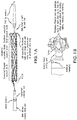
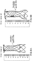
- a prosthesis for transcatheter cavopulmonary bypass situated on a distal region of a delivery system.
- the device has a tubular stent-like structure formed from ring shaped segments that have an undulating "zigzag" pattern.
- a first, proximal end of the prosthesis has an undulating end defined by the proximal-most ring of the prosthesis.
- the distal end has a similar undulating end formed from a ring of undulating material, but the material is heat treated such that it "flips" from a first direction that is generally parallel to a central longitudinal axis of the prosthesis, and relaxes into a bent over flange having a tip that is generally perpendicular to the longitudinal axis of the prosthesis when permitted to expand.
- the flange can be oriented at any suitable angle with respect to the longitudinal axis, and is preferably perpendicular thereto, or forms a slightly acute angle with respect to the wall of the prosthesis (e.g., between 70 and 90 degrees).
- the flange is useful for pulling against the inside of a vessel or other tissue wall when the remaining prosthesis is advanced through an opening in such vessel or other tissue wall, preventing pull through, and permitting a facilitated anastomosis procedure generally, as well as for Glenn and Fontan procedures.
- the proximal end of the prosthesis receives a tether therethrough that is routed through the windings of the undulating ring.
- the tethers are withdrawn proximally through a tubular member (e.g., a sheath) that also passes a core member therethrough that forms the core, or push rod of the delivery system.
- the core is slidably disposable with respect to the sheath.
- While adjacent undulating rings of the prosthesis particularly near the distal end of the prosthesis can be connected to each other (e.g., by sewing), they can also be kept independent of one another, and be attached to an inner and/or outer tubular fabric layer.
- the rigidity of the prosthesis is selected and/or configured to provide a desired performance.
- the distal end is relatively rigid to maintain an opening in the wall of a vessel or other organ in an open state that the prosthesis traverses through by resisting the force of the vessel wall to want to "close" the hole in itself.
- the proximal region is less rigid and can accommodate increasing vessel curvature of the vessel that it is mounted in.
- the delivery system typically includes an atraumatic distal tip that can pass a guidewire therethrough, and may be provided with one or more radiopaque markers to facilitate visualization under fluoroscopy, for example.
- the distal end or end region of the sheath of the delivery system (that surrounds the prosthesis when loaded onto the delivery system) can also include a radiopaque marker.
- FIGS. 2A-2D illustrate loading of the prosthesis on the core member of the delivery system using a clam shell like loading tool described in further detail below with respect to FIG. 12 .
- FIG. 2C illustrates the delivery system in a collapsed condition.
- the delivery system includes the aforementioned core member defining a guide wire lumen therethrough.
- the sheath is fitted over the core, and the tethers run between the components in the annular space between the core and sheath.
- the flared distal end of the prosthesis flips over from zero to 90 degrees as the sheath is advanced proximally.
- the proximal end of the prosthesis is held radially inwardly by the tether until tension of the tether is released. Tension can be reapplied to the tether to permit the prosthesis to be fully removable unless the tether is removed.
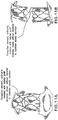
- FIG. 4a shows the disclosed prosthesis for a Glenn procedure.
- the distal region on the prosthesis is flexible to permit passage of the prosthesis through a curved vessel.
- FIG. 4D shows the distal flanged end of the prosthesis pulling against the inner wall of the main pulmonary artery (MPA), with the proximal end of the prosthesis extending into the superior vena cava in a Glenn procedure.
- MPA main pulmonary artery
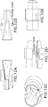
- FIG. 5A shows a schematic perspective view of a Fontan-type prosthesis
- FIG. 5B shows a side view schematic of such a prosthesis.
- Adjoining rings of the framework of the prosthesis are attached (e.g., by stitching) to a tubular fabric that preferably passes through the rings of the framework, wherein the framework is made, for example, of .014 inch diameter NiTi.
- the longitudinal dimension of each structural ring can be different.
- region "A" of the prosthesis can be comparatively stiff, wherein the rings can be attached to each other directly or via the fabric, wherein regions B, C, D, and E can have different, lower stiffnesses.
- FIG. 6A illustrates a first embodiment of a prosthesis for a Fontan procedure.
- the body is similar to that of the prosthesis in FIG. 5 , but is made, for example, from .013 inch diameter Ni Ti wire.
- FIG. 6B illustrates a second embodiment that is also formed from the same wire, but the flange is formed at a steeper angle to create an increased flip, or displacement, of the distal flange when the prosthesis is deployed.
- the prosthesis can include one or more (e.g., 2) fenestrations through the fabric in a central region thereof to permit leakage into the right atrium when the prosthesis spans from its distal end situated within the main pulmonary artery to the superior vena cava.
- the below chart illustrates suitable dimensions for the prosthesis illustrated in FIG.
- FIG. 7 illustrates an animal model wherein two prostheses are installed as disclosed herein using the disclosed delivery system; one in a Glenn procedure (connecting the SVC to the MPA to supply blood from the superior vena cava (SVC) to the main pulmonary artery (MPA)), and one in a Fontan procedure (connecting the inferior vena cava (IVC) through the ventricle to the main pulmonary artery (MPA)), wherein the prosthesis includes fenestrations to permit leakage through the prosthesis into the ventricle.
- a Glenn procedure connecting the SVC to the MPA to supply blood from the superior vena cava (SVC) to the main pulmonary artery (MPA)
- Fontan procedure connecting the inferior vena cava (IVC) through the ventricle to the main pulmonary artery (MPA)
- the prosthesis includes fenestrations to permit leakage through the prosthesis into the ventricle.
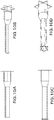
- FIG. 8A shows the delivery system with the prosthesis (for the Glenn or Fontan procedure) mounted thereon.
- FIG. 8B shows the core and distal tip advanced distally, and the distal flared end of the prosthesis deployed.
- FIG. 8C shows a close up of the flared distal end of the prosthesis.
- FIG. 8D shows the prosthesis mostly deployed, but the tether tensioned so as to keep the proximal end of the prosthesis held radially inwardly.
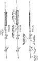
- FIGS. 9A and 9B show two different embodiments of a prosthesis as described above, FIG. 9C shows the prosthesis collapsed and within a sheath of the delivery system, whereas FIG. 9D shows the proximal ends of the delivery systems for each prosthesis.
- FIG. 9A and 9B show two different embodiments of a prosthesis as described above, FIG. 9C shows the prosthesis collapsed and within a sheath of the delivery system, whereas FIG. 9D shows the proximal ends of the delivery systems for
- the distal tip acts as a strain relief from a guidewire extending distally outwardly of a central guidewire lumen of the device. As such, while it is preferable to have the tip be relatively long, it is also useful to have it not be too long so as to prevent the delivery system from navigating a relatively narrow lumen when entering it obliquely.
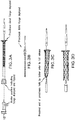
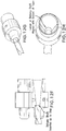
- FIGS. 10A-10B show side and isometric views of a prosthesis having a flanged distal end.
- FIGS. 10CA-10D show side and isometric views of a prosthesis having a flanged distal end as well as a flanged proximal end (upon prosthesis deployment).
- the illustrated prostheses also include a first section of relatively large diameter, such as near the flanged end, that transitions to a region of lower diameter by way of a transition region.
- the prosthesis can also be of adjustable telescoping length. The inside diameter preferably remains substantially unchanged when the prosthesis is adjusted in length.
- FIGS. 11A-11B show a flanged prosthesis of adjustable length having two flanged ends attached to tubular structural regions, that are in turn structurally joined in a central region by an elastic member, such as a spring.
- a tubular fabric member preferably traverses the inside or the outside of the length of the prosthesis.
- the prosthesis is shown without such a tubular fabric member for illustrative purposes, and each end can be of a different diameter from the other.
- Such a prosthesis can be useful, for example, for forming a shunt from the descending aorta to the main pulmonary artery to decompress the aorta.
- the length can be adjusted of the prosthesis, and tension can be maintained on the prosthesis by way of the spring, helping the flanged ends to seat against the inner walls of the aorta and the MPA.
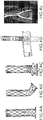
- FIGS. 12A-12H illustrate aspects of a prosthesis loading tool in accordance with the disclosure.
- the loading tool includes two halves, the inner faces of which are illustrated in FIGS. 12A and 12B .
- An interior channel including a first funnel portion necking down from a relatively large diameter to a relatively small diameter transitions into a second region of constant diameter, but wherein a step, or shoulder is present on the region of smaller diameter that effectively results in the funnel portion having a slightly smaller diameter than the region of constant diameter.
- the two halves align and mate with each other by way of a pair of protrusions on one half of the tool being received by a pair of indentations, or holes, on the other half of the tool.
- the distal end of the sheath that will cover the prosthesis is inserted into the end of the prosthesis having the portion of constant diameter until it abuts the shoulder.
- the central shaft of the delivery system passes through the sheath and the funnel section.
- the prosthesis, loaded with the tether on its proximal end, is then advanced into the funnel and is necked down to fit inside the sheath, but surrounding the central shaft, or tubular core member, of the delivery system. Advancing the prosthesis into the funnel section helps effectuate the compression. After the prosthesis is loaded, the loading tool is simply removed.
- the delivery system is advanced to a position where the prosthesis should be deployed.
- the distal tip and core of the guidewire are then advanced distally as well as the prosthesis, and the prosthesis flange is deployed thorough an opening in a wall of a vessel or other tissue wall.
- the flanged end then urges against the inner wall of the vessel.
- a corresponding marker can be used on the proximal end of the delivery system to show at what point of relative advancement the flange has been deployed.
- the delivery system is then pulled proximally slightly to seat the flange. When satisfied with seating, the user holds the inner shaft of the delivery system and pulls back on outer sheath to release the entire implant.
- the tether can then be de-tensioned to open the proximal end of implant. Finally, the user can pull on one end of the tether to remove it from the implant, and the delivery system can be removed. However, if desired, prior to removal of the tether, the tether can be re-tensioned, causing the proximal end of the prosthesis to collapse radially inwardly, and the prosthesis can be withdrawn into the sheath of the delivery system, and removed.
Claims (8)
- Radial selbstexpandierender Endograft-Stent, umfassend:einen distalen, selbstexpandierenden Flansch, der so gestaltet ist, dass er sich allgemein senkrecht in Bezug auf einen Körper der Prothese umdreht, um den Sitz der Prothese an einer Gewebewand zu unterstützen;ein distales Segment, das sich von dem distalen Flansch proximal erstreckt, das eine ausreichende Steifheit besitzt, um eine durch eine Gefäßwand ausgebildete Öffnung aufrechtzuerhalten;ein nachgiebiges mittleres Segment, das sich von dem distalen Segment proximal erstreckt, wobei das mittlere Segment nachgiebiger ist als das distale Segment und an einem röhrenförmigen Gewebe angebrachte, unabhängig bewegliche, gewellte Stützringe aufweist, wobei die kombinierte Struktur Flexibilität und Compliance für eine vollständige Durchgängigkeit im gebogenen Zustand bereitstellt, wobei das Segment so gestaltet ist, dass es eine Biegung um bis zu 90 Grad ermöglicht;ein proximales Segment mit einer Mehrzahl benachbarter, gewellter Stützringe, die miteinander verbunden sind, wobei das proximale Segment ausreichend steif ist für einen Sitz in einer Gefäßwand sowie um gegen diese zu drücken; undein proximales Ende, das eine Mehrzahl von Öffnungen um das proximale Ende zur Aufnahme einer Schnur aufweist, die durch die Öffnungen gefädelt ist, um zu bewirken, dass die Prothese radial einwärts zusammenfällt, wenn Spannung auf die Schnur ausgeübt wird.
- Zufuhrsystem, das die Prothese nach Anspruch 1 aufweist, wobei die Prothese an einem longitudinal inneren Element und innerhalb einer einziehbaren Schleuse angebracht ist.
- Zufuhrsystem nach Anspruch 2, wobei sich beide Enden der Schnur, die durch die Prothese geführt wird, proximal durch und aus einem proximalen Bereich des Zufuhrsystems erstrecken.
- Zufuhrsystem nach Anspruch 3, das ferner eine erste Gruppe röntgendichter Markierungen nahe dem distalen Ende des Zufuhrsystems umfasst sowie eine zweite Gruppe von Markierungen, die während einer Prozedur außerhalb des Patienten sichtbar sind, welche die relative Position des Zufuhrsystems und der Prothese anzeigen, wobei die erste und die zweite Gruppe von Markierungen während der Prozedur in Passgenauigkeit zueinander gehalten werden.
- Zufuhrsystem nach Anspruch 4, wobei sich die erste Gruppe von Markierungen an einer distalen atraumatischen Spitze des Zufuhrsystems aus Eisenoxid befindet, um die Navigation während einer MRI oder einer anderen bildgebenden Methode zu erleichtern, um das Zufuhrsystem präzise zu positionieren, und wobei die zweite Gruppe von Markierungen die relative longitudinale Position der Teile des Zufuhrsystems anzeigt.
- Zufuhrsystem nach Anspruch 4, wobei die Marker so gestaltet sind, dass sie es anzeigen, wenn der distale Flansch der Prothese in geeigneter Weise gestaltet ist, um an einer Innenseite der Wand eines Lumen zu ziehen.
- Prothese nach Anspruch 1, die ferner einen aufgeweiteten oder glockenförmigen proximalen Bereich zur Unterstützung der Anlagerung an die Innenwand eines Lumen aufweist.
- Prothese nach Anspruch 1, die ferner mindestens eine Fensteranordnung durch eine ihrer Seitenwände definiert, um ein Austreten von Körperfluid durch die Fensteranordnung zu ermöglichen.
Applications Claiming Priority (3)
| Application Number | Priority Date | Filing Date | Title |
|---|---|---|---|
| US201562219118P | 2015-09-15 | 2015-09-15 | |
| US201662363716P | 2016-07-18 | 2016-07-18 | |
| PCT/US2016/052005 WO2017049003A1 (en) | 2015-09-15 | 2016-09-15 | Devices and methods for effectuating percutaneous glenn and fontan procedures |
Publications (3)
| Publication Number | Publication Date |
|---|---|
| EP3349687A1 EP3349687A1 (de) | 2018-07-25 |
| EP3349687A4 EP3349687A4 (de) | 2019-06-26 |
| EP3349687B1 true EP3349687B1 (de) | 2020-09-09 |
Family
ID=58257893
Family Applications (1)
| Application Number | Title | Priority Date | Filing Date |
|---|---|---|---|
| EP16847336.1A Active EP3349687B1 (de) | 2015-09-15 | 2016-09-15 | Vorrichtungen zur durchführung perkutaner glenn- und fontan-eingriffe |
Country Status (4)
| Country | Link |
|---|---|
| US (3) | US10426482B2 (de) |
| EP (1) | EP3349687B1 (de) |
| JP (1) | JP6869967B2 (de) |
| WO (1) | WO2017049003A1 (de) |
Families Citing this family (6)
| Publication number | Priority date | Publication date | Assignee | Title |
|---|---|---|---|---|
| US10426482B2 (en) * | 2015-09-15 | 2019-10-01 | The United States Of America, As Represented By The Secretary, Department Of Health And Human Services | Devices and methods for effectuating percutaneous Glenn and Fontan procedures |
| WO2019046852A1 (en) * | 2017-09-01 | 2019-03-07 | Nasser Rafiee | PERCUTANEOUS DERIVATION DEVICES AND ASSOCIATED METHODS |
| WO2020061379A1 (en) * | 2018-09-19 | 2020-03-26 | NXT Biomedical | Methods and technology for creating connections and shunts between vessels and chambers of biologic structures |
| US20200101270A1 (en) * | 2018-09-24 | 2020-04-02 | Michael Warren Sutherland | Pulmonary arterial compliance enhancement and control device |
| CA3129020A1 (en) | 2019-02-07 | 2020-08-13 | Nxt Biomedical, Llc | Rivet shunt and method of deployment |
| WO2021025905A1 (en) * | 2019-08-06 | 2021-02-11 | Edwards Lifesciences Corporation | External cardiac bypass shunting |
Family Cites Families (155)
| Publication number | Priority date | Publication date | Assignee | Title |
|---|---|---|---|---|
| CA1069652A (en) | 1976-01-09 | 1980-01-15 | Alain F. Carpentier | Supported bioprosthetic heart valve with compliant orifice ring |
| AR221872A1 (es) | 1979-03-16 | 1981-03-31 | Liotta Domingo S | Mejoras en valvulas cardiacas impantables |
| IT1208326B (it) | 1984-03-16 | 1989-06-12 | Sorin Biomedica Spa | Protesi valvolare cardiaca provvista di lembi valvolari di tessuto biologico |
| CH672247A5 (de) | 1986-03-06 | 1989-11-15 | Mo Vysshee Tekhnicheskoe Uchil | |
| US5411552A (en) | 1990-05-18 | 1995-05-02 | Andersen; Henning R. | Valve prothesis for implantation in the body and a catheter for implanting such valve prothesis |
| ES2051664T3 (es) | 1991-05-08 | 1997-04-01 | Nika Health Products Ltd | Procedimiento y aparato para la fabricacion de una protesis de valvula de corazon. |
| US5449384A (en) | 1992-09-28 | 1995-09-12 | Medtronic, Inc. | Dynamic annulus heart valve employing preserved porcine valve leaflets |
| US5639278A (en) * | 1993-10-21 | 1997-06-17 | Corvita Corporation | Expandable supportive bifurcated endoluminal grafts |
| CA2158976C (en) | 1995-02-07 | 2005-05-24 | Thomas E. Watson, Jr. | Telescoping serial elastic band ligator |
| WO1996036297A1 (fr) * | 1995-05-19 | 1996-11-21 | Kanji Inoue | Instrument de transplantation, procede pour le courber et procede pour le transplanter |
| ES2293653T3 (es) * | 1995-12-14 | 2008-03-16 | Gore Enterprise Holdings, Inc. | Injerto de stent resistente al retorcimiento. |
| US5861028A (en) | 1996-09-09 | 1999-01-19 | Shelhigh Inc | Natural tissue heart valve and stent prosthesis and method for making the same |
| US5749921A (en) * | 1996-02-20 | 1998-05-12 | Medtronic, Inc. | Apparatus and methods for compression of endoluminal prostheses |
| US6090136A (en) * | 1996-07-29 | 2000-07-18 | Radiance Medical Systems, Inc. | Self expandable tubular support |
| EP0850607A1 (de) | 1996-12-31 | 1998-07-01 | Cordis Corporation | Klappenprothese zur Implantation in Körperkanälen |
| US5928281A (en) | 1997-03-27 | 1999-07-27 | Baxter International Inc. | Tissue heart valves |
| US5895410A (en) | 1997-09-12 | 1999-04-20 | B. Braun Medical, Inc. | Introducer for an expandable vascular occlusion device |
| US7491232B2 (en) | 1998-09-18 | 2009-02-17 | Aptus Endosystems, Inc. | Catheter-based fastener implantation apparatus and methods with implantation force resolution |
| US6106510A (en) | 1998-05-28 | 2000-08-22 | Medtronic, Inc. | Extruded guide catheter shaft with bump extrusion soft distal segment |
| EP1112041A1 (de) | 1998-09-10 | 2001-07-04 | Percardia, Inc. | Tmr vorrichtung |
| CA2344252A1 (en) | 1998-09-18 | 2000-03-30 | United States Surgical Corporation | Endovascular fastener applicator |
| US6059769A (en) | 1998-10-02 | 2000-05-09 | Medtronic, Inc. | Medical catheter with grooved soft distal segment |
| US6152937A (en) | 1998-11-06 | 2000-11-28 | St. Jude Medical Cardiovascular Group, Inc. | Medical graft connector and methods of making and installing same |
| US6059824A (en) * | 1998-12-23 | 2000-05-09 | Taheri; Syde A. | Mated main and collateral stent and method for treatment of arterial disease |
| US6736845B2 (en) | 1999-01-26 | 2004-05-18 | Edwards Lifesciences Corporation | Holder for flexible heart valve |
| US6364905B1 (en) | 1999-01-27 | 2002-04-02 | Sulzer Carbomedics Inc. | Tri-composite, full root, stentless valve |
| US6248122B1 (en) * | 1999-02-26 | 2001-06-19 | Vascular Architects, Inc. | Catheter with controlled release endoluminal prosthesis |
| EP1180976A1 (de) * | 1999-05-03 | 2002-02-27 | Ventrica Inc. | Verfahren und vorrichtung zum platzieren eines kanals in flüssigkeitsverbindung mit einem zielgefäss |
| US6790229B1 (en) | 1999-05-25 | 2004-09-14 | Eric Berreklouw | Fixing device, in particular for fixing to vascular wall tissue |
| US6346116B1 (en) | 1999-08-03 | 2002-02-12 | Medtronic Ave, Inc. | Distal protection device |
| SE515231C2 (sv) * | 1999-10-13 | 2001-07-02 | Jan Otto Solem | Täckt stent och sätt att tillverka densamma |
| US20070043435A1 (en) | 1999-11-17 | 2007-02-22 | Jacques Seguin | Non-cylindrical prosthetic valve system for transluminal delivery |
| US7195641B2 (en) | 1999-11-19 | 2007-03-27 | Advanced Bio Prosthetic Surfaces, Ltd. | Valvular prostheses having metal or pseudometallic construction and methods of manufacture |
| US6458153B1 (en) | 1999-12-31 | 2002-10-01 | Abps Venture One, Ltd. | Endoluminal cardiac and venous valve prostheses and methods of manufacture and delivery thereof |
| IL153753A0 (en) | 2002-12-30 | 2003-07-06 | Neovasc Medical Ltd | Varying-diameter vascular implant and balloon |
| US6953476B1 (en) | 2000-03-27 | 2005-10-11 | Neovasc Medical Ltd. | Device and method for treating ischemic heart disease |
| US6454799B1 (en) | 2000-04-06 | 2002-09-24 | Edwards Lifesciences Corporation | Minimally-invasive heart valves and methods of use |
| US6602271B2 (en) | 2000-05-24 | 2003-08-05 | Medtronic Ave, Inc. | Collapsible blood filter with optimal braid geometry |
| US7510572B2 (en) | 2000-09-12 | 2009-03-31 | Shlomo Gabbay | Implantation system for delivery of a heart valve prosthesis |
| US7374571B2 (en) | 2001-03-23 | 2008-05-20 | Edwards Lifesciences Corporation | Rolled minimally-invasive heart valves and methods of manufacture |
| US6733525B2 (en) | 2001-03-23 | 2004-05-11 | Edwards Lifesciences Corporation | Rolled minimally-invasive heart valves and methods of use |
| US6911036B2 (en) | 2001-04-03 | 2005-06-28 | Medtronic Vascular, Inc. | Guidewire apparatus for temporary distal embolic protection |
| US7044958B2 (en) | 2001-04-03 | 2006-05-16 | Medtronic Vascular, Inc. | Temporary device for capturing embolic material |
| US6818006B2 (en) | 2001-04-03 | 2004-11-16 | Medtronic Vascular, Inc. | Temporary intraluminal filter guidewire |
| US6866677B2 (en) | 2001-04-03 | 2005-03-15 | Medtronic Ave, Inc. | Temporary intraluminal filter guidewire and methods of use |
| FR2826863B1 (fr) | 2001-07-04 | 2003-09-26 | Jacques Seguin | Ensemble permettant la mise en place d'une valve prothetique dans un conduit corporel |
| US20030065386A1 (en) | 2001-09-28 | 2003-04-03 | Weadock Kevin Shaun | Radially expandable endoprosthesis device with two-stage deployment |
| JP4398244B2 (ja) | 2001-10-04 | 2010-01-13 | ネオヴァスク メディカル リミテッド | 流量減少インプラント |
| EP1448117B1 (de) | 2001-11-28 | 2013-05-22 | Aptus Endosystems, Inc. | Endovaskuläres system zum ausbessern eines aneurysmas |
| US7147657B2 (en) | 2003-10-23 | 2006-12-12 | Aptus Endosystems, Inc. | Prosthesis delivery systems and methods |
| US20050177180A1 (en) | 2001-11-28 | 2005-08-11 | Aptus Endosystems, Inc. | Devices, systems, and methods for supporting tissue and/or structures within a hollow body organ |
| US20050070992A1 (en) | 2001-11-28 | 2005-03-31 | Aptus Endosystems, Inc. | Prosthesis systems and methods sized and configured for the receipt and retention of fasteners |
| US7137993B2 (en) * | 2001-12-03 | 2006-11-21 | Xtent, Inc. | Apparatus and methods for delivery of multiple distributed stents |
| US7105021B2 (en) * | 2002-04-25 | 2006-09-12 | Scimed Life Systems, Inc. | Implantable textile prostheses having PTFE cold drawn yarns |
| US20060106449A1 (en) | 2002-08-08 | 2006-05-18 | Neovasc Medical Ltd. | Flow reducing implant |
| US20060106450A1 (en) | 2002-08-08 | 2006-05-18 | Neovasc Medical Ltd. | Geometric flow regulator |
| US8075585B2 (en) | 2002-08-29 | 2011-12-13 | Stryker Corporation | Device and method for treatment of a vascular defect |
| US8518096B2 (en) * | 2002-09-03 | 2013-08-27 | Lifeshield Sciences Llc | Elephant trunk thoracic endograft and delivery system |
| US7404824B1 (en) | 2002-11-15 | 2008-07-29 | Advanced Cardiovascular Systems, Inc. | Valve aptation assist device |
| US7189259B2 (en) | 2002-11-26 | 2007-03-13 | Clemson University | Tissue material and process for bioprosthesis |
| US7399315B2 (en) | 2003-03-18 | 2008-07-15 | Edwards Lifescience Corporation | Minimally-invasive heart valve with cusp positioners |
| US7294135B2 (en) | 2003-03-20 | 2007-11-13 | Medtronic Vascular, Inc | Control handle for intraluminal devices |
| US20050049675A1 (en) | 2003-03-28 | 2005-03-03 | Board Of Regents, The University Of Texas System | Medical devices and related methods |
| JP2004298472A (ja) * | 2003-03-31 | 2004-10-28 | Clinical Supply:Kk | ステント |
| US7998188B2 (en) | 2003-04-28 | 2011-08-16 | Kips Bay Medical, Inc. | Compliant blood vessel graft |
| US7316706B2 (en) | 2003-06-20 | 2008-01-08 | Medtronic Vascular, Inc. | Tensioning device, system, and method for treating mitral valve regurgitation |
| US7201772B2 (en) | 2003-07-08 | 2007-04-10 | Ventor Technologies, Ltd. | Fluid flow prosthetic device |
| US7160322B2 (en) | 2003-08-13 | 2007-01-09 | Shlomo Gabbay | Implantable cardiac prosthesis for mitigating prolapse of a heart valve |
| WO2005037133A2 (en) | 2003-10-10 | 2005-04-28 | Arshad Quadri | System and method for endoluminal grafting of bifurcated and branched vessels |
| US7955384B2 (en) | 2003-11-12 | 2011-06-07 | Medtronic Vascular, Inc. | Coronary sinus approach for repair of mitral valve regurgitation |
| EP1689329A2 (de) | 2003-11-12 | 2006-08-16 | Medtronic Vascular, Inc. | Herzklappen-annulus-reduktionssystem |
| US7716801B2 (en) | 2003-11-24 | 2010-05-18 | Medtronic Vascular, Inc. | Low-profile distal protection device |
| JP2005178627A (ja) | 2003-12-19 | 2005-07-07 | Toyota Motor Corp | 車両の統合制御システム |
| US7445631B2 (en) | 2003-12-23 | 2008-11-04 | Sadra Medical, Inc. | Methods and apparatus for endovascularly replacing a patient's heart valve |
| US7959666B2 (en) | 2003-12-23 | 2011-06-14 | Sadra Medical, Inc. | Methods and apparatus for endovascularly replacing a heart valve |
| WO2005076973A2 (en) | 2004-02-05 | 2005-08-25 | Children's Medical Center Corporation | Transcatheter delivery of a replacement heart valve |
| US9039724B2 (en) | 2004-03-19 | 2015-05-26 | Aga Medical Corporation | Device for occluding vascular defects |
| WO2005107650A2 (en) | 2004-05-05 | 2005-11-17 | Direct Flow Medical, Inc. | Unstented heart valve with formed in place support structure |
| US7842069B2 (en) | 2004-05-07 | 2010-11-30 | Nmt Medical, Inc. | Inflatable occluder |
| US9706997B2 (en) * | 2004-08-27 | 2017-07-18 | Rox Medical, Inc. | Device and method for establishing an artificial arterio-venous fistula |
| US8926545B2 (en) * | 2004-08-27 | 2015-01-06 | Rox Medical, Inc. | Device and method for establishing an artificial arterio-venous fistula |
| US7780721B2 (en) * | 2004-09-01 | 2010-08-24 | C. R. Bard, Inc. | Stent and method for manufacturing the stent |
| FR2874813B1 (fr) | 2004-09-07 | 2007-06-22 | Perouse Soc Par Actions Simpli | Prothese valvulaire |
| US7682352B2 (en) | 2004-09-28 | 2010-03-23 | Medtronic Vascular, Inc. | Catheter with curved distal section having reinforcing strip and method of making same |
| US20060085012A1 (en) | 2004-09-28 | 2006-04-20 | Medtronic Vascular, Inc. | Torquing device delivered over a guidewire to rotate a medical fastener |
| WO2006121855A2 (en) | 2005-05-06 | 2006-11-16 | Johns Hopkins University | Transcaval mesenteric venous anastomosis and access system |
| US7914569B2 (en) | 2005-05-13 | 2011-03-29 | Medtronics Corevalve Llc | Heart valve prosthesis and methods of manufacture and use |
| US20070067029A1 (en) | 2005-09-16 | 2007-03-22 | Shlomo Gabbay | Support apparatus to facilitate implantation of cardiac prosthesis |
| DE102005052628B4 (de) | 2005-11-04 | 2014-06-05 | Jenavalve Technology Inc. | Selbstexpandierendes, flexibles Drahtgeflecht mit integrierter Klappenprothese für den transvaskulären Herzklappenersatz und ein System mit einer solchen Vorrichtung und einem Einführkatheter |
| EP1951352B1 (de) | 2005-11-10 | 2017-01-11 | Edwards Lifesciences CardiAQ LLC | Ballon-expandierbarer, selbst-expandierbarer gefässprothesen-verbindungsstent |
| EP2583640B1 (de) | 2006-02-16 | 2022-06-22 | Venus MedTech (HangZhou), Inc. | Minimalinvasiver Herzklappenersatz |
| WO2007106755A1 (en) | 2006-03-10 | 2007-09-20 | Arbor Surgical Technologies, Inc. | Valve introducers and methods for making and using them |
| EP3593761A1 (de) | 2006-04-12 | 2020-01-15 | Medtronic Vascular, Inc. | Annuloplastievorrichtung mit spiralförmigem anker |
| US7699892B2 (en) | 2006-04-12 | 2010-04-20 | Medtronic Vascular, Inc. | Minimally invasive procedure for implanting an annuloplasty device |
| US7442207B2 (en) | 2006-04-21 | 2008-10-28 | Medtronic Vascular, Inc. | Device, system, and method for treating cardiac valve regurgitation |
| EP2023860A2 (de) | 2006-04-29 | 2009-02-18 | Arbor Surgical Technologies, Inc. | Mehrteilige herzklappenprothesenanordnungen sowie vorrichtung und verfahren zu ihrer einsetzung |
| US20070293942A1 (en) | 2006-06-16 | 2007-12-20 | Daryush Mirzaee | Prosthetic valve and deployment method |
| US20090306768A1 (en) | 2006-07-28 | 2009-12-10 | Cardiaq Valve Technologies, Inc. | Percutaneous valve prosthesis and system and method for implanting same |
| US8052750B2 (en) | 2006-09-19 | 2011-11-08 | Medtronic Ventor Technologies Ltd | Valve prosthesis fixation techniques using sandwiching |
| US8388680B2 (en) | 2006-10-18 | 2013-03-05 | Guided Delivery Systems, Inc. | Methods and devices for catheter advancement and delivery of substances therethrough |
| CA2664557C (en) * | 2006-11-07 | 2015-05-26 | David Stephen Celermajer | Devices and methods for the treatment of heart failure |
| US8353954B2 (en) | 2006-12-19 | 2013-01-15 | St. Jude Medical, Inc. | Prosthetic heart valve including stent structure and tissue leaflets, and related methods |
| US8070802B2 (en) | 2007-02-23 | 2011-12-06 | The Trustees Of The University Of Pennsylvania | Mitral valve system |
| US20080208328A1 (en) | 2007-02-23 | 2008-08-28 | Endovalve, Inc. | Systems and Methods For Placement of Valve Prosthesis System |
| CA2679614C (en) * | 2007-03-06 | 2014-11-18 | William A. Cook Australia Pty. Ltd | Endovascular deployment device |
| US7806917B2 (en) | 2007-04-17 | 2010-10-05 | Medtronic Vascular, Inc. | Stent graft fixation system and method |
| WO2009045334A1 (en) | 2007-09-28 | 2009-04-09 | St. Jude Medical, Inc. | Collapsible/expandable prosthetic heart valves with native calcified leaflet retention features |
| US8992593B2 (en) | 2007-12-26 | 2015-03-31 | Cook Medical Technologies Llc | Apparatus and methods for deployment of a modular stent-graft system |
| US7806919B2 (en) | 2008-04-01 | 2010-10-05 | Medtronic Vascular, Inc. | Double-walled stent system |
| AU2009240565B2 (en) | 2008-04-23 | 2013-08-22 | Medtronic, Inc. | Stented heart valve devices |
| US7972370B2 (en) | 2008-04-24 | 2011-07-05 | Medtronic Vascular, Inc. | Stent graft system and method of use |
| US20090270976A1 (en) | 2008-04-24 | 2009-10-29 | Medtronic Vascular, Inc. | Stent Graft Fixation System and Method of Use |
| CA2726807C (en) | 2008-06-05 | 2016-05-31 | Medtronic, Inc. | Connection systems for two piece prosthetic heart valve assemblies and methods for making and using them |
| EP2901966B1 (de) | 2008-09-29 | 2016-06-29 | Edwards Lifesciences CardiAQ LLC | Herzklappe |
| EP2341871B1 (de) | 2008-10-01 | 2017-03-22 | Edwards Lifesciences CardiAQ LLC | Abgabesystem für ein gefässimplantat |
| US8986361B2 (en) | 2008-10-17 | 2015-03-24 | Medtronic Corevalve, Inc. | Delivery system for deployment of medical devices |
| US8905961B2 (en) | 2008-12-19 | 2014-12-09 | St. Jude Medical, Inc. | Systems, apparatuses, and methods for cardiovascular conduits and connectors |
| US8308798B2 (en) | 2008-12-19 | 2012-11-13 | Edwards Lifesciences Corporation | Quick-connect prosthetic heart valve and methods |
| US20100174363A1 (en) | 2009-01-07 | 2010-07-08 | Endovalve, Inc. | One Piece Prosthetic Valve Support Structure and Related Assemblies |
| US8998982B2 (en) | 2009-01-12 | 2015-04-07 | Valve Medical Ltd. | Method and apparatus for fine adjustment of a percutaneous valve structure |
| US9402720B2 (en) | 2009-01-12 | 2016-08-02 | Valve Medical Ltd. | Modular percutaneous valve structure and delivery method |
| US9681950B2 (en) | 2009-01-12 | 2017-06-20 | Valve Medical Ltd. | System and method for placing a percutaneous valve device |
| US20100217382A1 (en) | 2009-02-25 | 2010-08-26 | Edwards Lifesciences | Mitral valve replacement with atrial anchoring |
| EP2408399B1 (de) | 2009-03-17 | 2023-11-01 | Mitrassist Medical Ltd. | Herzklappenprothese mit faltbarer klappe |
| EP2416739B1 (de) | 2009-04-10 | 2016-06-08 | Lon Sutherland Annest | Impantierbares gerüst mit einer öffnung für eine klappenprothese bzw. bioklappenprothese |
| EP2810620B1 (de) | 2009-04-15 | 2022-09-14 | Edwards Lifesciences CardiAQ LLC | Gefäßimplantat und Freisetzungssystem |
| FR2947716B1 (fr) | 2009-07-10 | 2011-09-02 | Cormove | Implant prothetique ameliore |
| US9730790B2 (en) | 2009-09-29 | 2017-08-15 | Edwards Lifesciences Cardiaq Llc | Replacement valve and method |
| US8449599B2 (en) | 2009-12-04 | 2013-05-28 | Edwards Lifesciences Corporation | Prosthetic valve for replacing mitral valve |
| EP3300695B1 (de) | 2009-12-08 | 2023-05-24 | Avalon Medical Ltd. | Vorrichtung und system zur neuplatzierung einer transkatheter-mitralklappe |
| CN102113921A (zh) | 2009-12-30 | 2011-07-06 | 微创医疗器械(上海)有限公司 | 一种介入式心脏瓣膜 |
| US9504562B2 (en) | 2010-01-12 | 2016-11-29 | Valve Medical Ltd. | Self-assembling modular percutaneous valve and methods of folding, assembly and delivery |
| US8579964B2 (en) | 2010-05-05 | 2013-11-12 | Neovasc Inc. | Transcatheter mitral valve prosthesis |
| EP4018966A1 (de) | 2010-06-21 | 2022-06-29 | Edwards Lifesciences CardiAQ LLC | Herzklappenersatz |
| RU100718U1 (ru) | 2010-07-08 | 2010-12-27 | Учреждение Российской академии медицинских наук Научный центр сердечно-сосудистой хирургии имени А.Н. Бакулева РАМН | Биопротез клапана сердца |
| US9132009B2 (en) | 2010-07-21 | 2015-09-15 | Mitraltech Ltd. | Guide wires with commissural anchors to advance a prosthetic valve |
| US20120143141A1 (en) * | 2010-08-03 | 2012-06-07 | Verkaik Josiah E | Conformal cannula device and related methods |
| US9463269B2 (en) | 2010-09-10 | 2016-10-11 | W. L. Gore & Associates, Inc. | Anastomotic devices and methods |
| US20120078360A1 (en) | 2010-09-23 | 2012-03-29 | Nasser Rafiee | Prosthetic devices, systems and methods for replacing heart valves |
| US9579193B2 (en) | 2010-09-23 | 2017-02-28 | Transmural Systems Llc | Methods and systems for delivering prostheses using rail techniques |
| US10321998B2 (en) | 2010-09-23 | 2019-06-18 | Transmural Systems Llc | Methods and systems for delivering prostheses using rail techniques |
| EP2618784B1 (de) | 2010-09-23 | 2016-05-25 | Edwards Lifesciences CardiAQ LLC | Künstliche herzklappen und vorrichtungen |
| WO2012061809A2 (en) | 2010-11-06 | 2012-05-10 | Mehr Medical Llc | Methods and systems for delivering prostheses using rail techniques |
| US20120184982A1 (en) * | 2011-01-19 | 2012-07-19 | Endologix, Inc. | Methods and Systems for Treating Aneurysms |
| KR20140030206A (ko) | 2011-04-26 | 2014-03-11 | 쓰리엠 이노베이티브 프로퍼티즈 컴파니 | 혼합 광가교결합 시스템을 갖는 감압 접착제 |
| WO2013028387A2 (en) * | 2011-08-11 | 2013-02-28 | Tendyne Holdings, Inc. | Improvements for prosthetic valves and related inventions |
| US9549817B2 (en) | 2011-09-22 | 2017-01-24 | Transmural Systems Llc | Devices, systems and methods for repairing lumenal systems |
| WO2013131069A1 (en) | 2012-03-02 | 2013-09-06 | Mehr Medical Llc | Prostheses |
| US20130158673A1 (en) * | 2011-12-15 | 2013-06-20 | Cook Medical Technologies Llc | Anti-Leakage Prosthesis |
| KR101501614B1 (ko) | 2012-03-29 | 2015-03-11 | 연세대학교 산학협력단 | 문합술용 스텐트 |
| ES2713401T3 (es) * | 2012-06-15 | 2019-05-21 | Phraxis Inc | Dispositivo de anclaje arterial y venoso formando un conector anastomótico |
| CA2905283C (en) * | 2013-03-15 | 2021-03-02 | Corvia Medical, Inc. | Devices and methods for retrievable intra-atrial implants |
| EP3122284B1 (de) | 2014-03-27 | 2021-01-13 | Nasser Rafiee | Vorrichtungen zum verschluss von transvaskulären oder transkameralen zugangsports |
| US10426482B2 (en) * | 2015-09-15 | 2019-10-01 | The United States Of America, As Represented By The Secretary, Department Of Health And Human Services | Devices and methods for effectuating percutaneous Glenn and Fontan procedures |
| WO2019046852A1 (en) | 2017-09-01 | 2019-03-07 | Nasser Rafiee | PERCUTANEOUS DERIVATION DEVICES AND ASSOCIATED METHODS |
-
2016
- 2016-09-15 US US15/267,075 patent/US10426482B2/en active Active
- 2016-09-15 JP JP2018514884A patent/JP6869967B2/ja active Active
- 2016-09-15 EP EP16847336.1A patent/EP3349687B1/de active Active
- 2016-09-15 WO PCT/US2016/052005 patent/WO2017049003A1/en active Application Filing
-
2019
- 2019-04-30 US US16/399,670 patent/US11179156B2/en active Active
-
2021
- 2021-08-31 US US17/462,190 patent/US11871928B2/en active Active
Non-Patent Citations (1)
| Title |
|---|
| None * |
Also Published As
| Publication number | Publication date |
|---|---|
| JP2018528009A (ja) | 2018-09-27 |
| US20220125430A1 (en) | 2022-04-28 |
| EP3349687A4 (de) | 2019-06-26 |
| US20170071722A1 (en) | 2017-03-16 |
| US11179156B2 (en) | 2021-11-23 |
| US11871928B2 (en) | 2024-01-16 |
| US20190321043A1 (en) | 2019-10-24 |
| WO2017049003A1 (en) | 2017-03-23 |
| US10426482B2 (en) | 2019-10-01 |
| JP6869967B2 (ja) | 2021-05-12 |
| EP3349687A1 (de) | 2018-07-25 |
Similar Documents
| Publication | Publication Date | Title |
|---|---|---|
| EP3349687B1 (de) | Vorrichtungen zur durchführung perkutaner glenn- und fontan-eingriffe | |
| JP7191339B2 (ja) | 改善された塞栓防御デバイスおよび方法 | |
| US10307241B2 (en) | Embolic protection devices and methods of use | |
| JP5106537B2 (ja) | プロテーゼの経皮的送達のための送達ツール | |
| CA2836422C (en) | Inversion delivery device and method for a prosthesis | |
| US9579182B2 (en) | Method for delivery of an embolic protection unit | |
| EP3043748A1 (de) | Ausrichtung einer implantierbaren medizinischen vorrichtung | |
| US20170196565A1 (en) | Method for coupling anatomical walls using a connector | |
| EP3691568A1 (de) | Perkutane shunt-vorrichtungen und zugehörige verfahren | |
| JP6967004B2 (ja) | 有窓移植片と充填構造体とを用いるシステム及び方法 | |
| AU2013201970B2 (en) | Delivery tool for percutaneous delivery of a prosthesis | |
| WO2022177618A1 (en) | Methods and systems for placing embolic filters in an aortic arch |
Legal Events
| Date | Code | Title | Description |
|---|---|---|---|
| STAA | Information on the status of an ep patent application or granted ep patent |
Free format text: STATUS: THE INTERNATIONAL PUBLICATION HAS BEEN MADE |
|
| PUAI | Public reference made under article 153(3) epc to a published international application that has entered the european phase |
Free format text: ORIGINAL CODE: 0009012 |
|
| STAA | Information on the status of an ep patent application or granted ep patent |
Free format text: STATUS: REQUEST FOR EXAMINATION WAS MADE |
|
| 17P | Request for examination filed |
Effective date: 20180403 |
|
| AK | Designated contracting states |
Kind code of ref document: A1 Designated state(s): AL AT BE BG CH CY CZ DE DK EE ES FI FR GB GR HR HU IE IS IT LI LT LU LV MC MK MT NL NO PL PT RO RS SE SI SK SM TR |
|
| AX | Request for extension of the european patent |
Extension state: BA ME |
|
| DAV | Request for validation of the european patent (deleted) | ||
| DAX | Request for extension of the european patent (deleted) | ||
| A4 | Supplementary search report drawn up and despatched |
Effective date: 20190524 |
|
| RIC1 | Information provided on ipc code assigned before grant |
Ipc: A61F 2/07 20130101ALI20190520BHEP Ipc: A61F 2/06 20130101ALI20190520BHEP Ipc: A61B 17/11 20060101AFI20190520BHEP Ipc: A61F 2/82 20130101ALI20190520BHEP Ipc: A61F 2/915 20130101ALI20190520BHEP |
|
| REG | Reference to a national code |
Ref country code: DE Ref legal event code: R079 Ref document number: 602016043871 Country of ref document: DE Free format text: PREVIOUS MAIN CLASS: A61F0002000000 Ipc: A61B0017110000 |
|
| RIC1 | Information provided on ipc code assigned before grant |
Ipc: A61F 2/82 20130101ALI20200113BHEP Ipc: A61B 17/11 20060101AFI20200113BHEP Ipc: A61F 2/07 20130101ALI20200113BHEP Ipc: A61F 2/06 20130101ALI20200113BHEP Ipc: A61F 2/915 20130101ALI20200113BHEP |
|
| GRAP | Despatch of communication of intention to grant a patent |
Free format text: ORIGINAL CODE: EPIDOSNIGR1 |
|
| STAA | Information on the status of an ep patent application or granted ep patent |
Free format text: STATUS: GRANT OF PATENT IS INTENDED |
|
| INTG | Intention to grant announced |
Effective date: 20200323 |
|
| GRAS | Grant fee paid |
Free format text: ORIGINAL CODE: EPIDOSNIGR3 |
|
| GRAA | (expected) grant |
Free format text: ORIGINAL CODE: 0009210 |
|
| STAA | Information on the status of an ep patent application or granted ep patent |
Free format text: STATUS: THE PATENT HAS BEEN GRANTED |
|
| AK | Designated contracting states |
Kind code of ref document: B1 Designated state(s): AL AT BE BG CH CY CZ DE DK EE ES FI FR GB GR HR HU IE IS IT LI LT LU LV MC MK MT NL NO PL PT RO RS SE SI SK SM TR |
|
| REG | Reference to a national code |
Ref country code: GB Ref legal event code: FG4D |
|
| REG | Reference to a national code |
Ref country code: AT Ref legal event code: REF Ref document number: 1310572 Country of ref document: AT Kind code of ref document: T Effective date: 20200915 Ref country code: CH Ref legal event code: EP |
|
| REG | Reference to a national code |
Ref country code: IE Ref legal event code: FG4D |
|
| REG | Reference to a national code |
Ref country code: DE Ref legal event code: R096 Ref document number: 602016043871 Country of ref document: DE |
|
| REG | Reference to a national code |
Ref country code: CH Ref legal event code: NV Representative=s name: TR-IP CONSULTING LLC, CH |
|
| REG | Reference to a national code |
Ref country code: LT Ref legal event code: MG4D |
|
| PG25 | Lapsed in a contracting state [announced via postgrant information from national office to epo] |
Ref country code: HR Free format text: LAPSE BECAUSE OF FAILURE TO SUBMIT A TRANSLATION OF THE DESCRIPTION OR TO PAY THE FEE WITHIN THE PRESCRIBED TIME-LIMIT Effective date: 20200909 Ref country code: SE Free format text: LAPSE BECAUSE OF FAILURE TO SUBMIT A TRANSLATION OF THE DESCRIPTION OR TO PAY THE FEE WITHIN THE PRESCRIBED TIME-LIMIT Effective date: 20200909 Ref country code: NO Free format text: LAPSE BECAUSE OF FAILURE TO SUBMIT A TRANSLATION OF THE DESCRIPTION OR TO PAY THE FEE WITHIN THE PRESCRIBED TIME-LIMIT Effective date: 20201209 Ref country code: FI Free format text: LAPSE BECAUSE OF FAILURE TO SUBMIT A TRANSLATION OF THE DESCRIPTION OR TO PAY THE FEE WITHIN THE PRESCRIBED TIME-LIMIT Effective date: 20200909 Ref country code: BG Free format text: LAPSE BECAUSE OF FAILURE TO SUBMIT A TRANSLATION OF THE DESCRIPTION OR TO PAY THE FEE WITHIN THE PRESCRIBED TIME-LIMIT Effective date: 20201209 Ref country code: GR Free format text: LAPSE BECAUSE OF FAILURE TO SUBMIT A TRANSLATION OF THE DESCRIPTION OR TO PAY THE FEE WITHIN THE PRESCRIBED TIME-LIMIT Effective date: 20201210 Ref country code: LT Free format text: LAPSE BECAUSE OF FAILURE TO SUBMIT A TRANSLATION OF THE DESCRIPTION OR TO PAY THE FEE WITHIN THE PRESCRIBED TIME-LIMIT Effective date: 20200909 |
|
| REG | Reference to a national code |
Ref country code: AT Ref legal event code: MK05 Ref document number: 1310572 Country of ref document: AT Kind code of ref document: T Effective date: 20200909 |
|
| REG | Reference to a national code |
Ref country code: NL Ref legal event code: MP Effective date: 20200909 |
|
| PG25 | Lapsed in a contracting state [announced via postgrant information from national office to epo] |
Ref country code: RS Free format text: LAPSE BECAUSE OF FAILURE TO SUBMIT A TRANSLATION OF THE DESCRIPTION OR TO PAY THE FEE WITHIN THE PRESCRIBED TIME-LIMIT Effective date: 20200909 Ref country code: LV Free format text: LAPSE BECAUSE OF FAILURE TO SUBMIT A TRANSLATION OF THE DESCRIPTION OR TO PAY THE FEE WITHIN THE PRESCRIBED TIME-LIMIT Effective date: 20200909 Ref country code: PL Free format text: LAPSE BECAUSE OF FAILURE TO SUBMIT A TRANSLATION OF THE DESCRIPTION OR TO PAY THE FEE WITHIN THE PRESCRIBED TIME-LIMIT Effective date: 20200909 |
|
| PG25 | Lapsed in a contracting state [announced via postgrant information from national office to epo] |
Ref country code: RO Free format text: LAPSE BECAUSE OF FAILURE TO SUBMIT A TRANSLATION OF THE DESCRIPTION OR TO PAY THE FEE WITHIN THE PRESCRIBED TIME-LIMIT Effective date: 20200909 Ref country code: PT Free format text: LAPSE BECAUSE OF FAILURE TO SUBMIT A TRANSLATION OF THE DESCRIPTION OR TO PAY THE FEE WITHIN THE PRESCRIBED TIME-LIMIT Effective date: 20210111 Ref country code: CZ Free format text: LAPSE BECAUSE OF FAILURE TO SUBMIT A TRANSLATION OF THE DESCRIPTION OR TO PAY THE FEE WITHIN THE PRESCRIBED TIME-LIMIT Effective date: 20200909 Ref country code: EE Free format text: LAPSE BECAUSE OF FAILURE TO SUBMIT A TRANSLATION OF THE DESCRIPTION OR TO PAY THE FEE WITHIN THE PRESCRIBED TIME-LIMIT Effective date: 20200909 Ref country code: SM Free format text: LAPSE BECAUSE OF FAILURE TO SUBMIT A TRANSLATION OF THE DESCRIPTION OR TO PAY THE FEE WITHIN THE PRESCRIBED TIME-LIMIT Effective date: 20200909 |
|
| PG25 | Lapsed in a contracting state [announced via postgrant information from national office to epo] |
Ref country code: IS Free format text: LAPSE BECAUSE OF FAILURE TO SUBMIT A TRANSLATION OF THE DESCRIPTION OR TO PAY THE FEE WITHIN THE PRESCRIBED TIME-LIMIT Effective date: 20210109 Ref country code: AL Free format text: LAPSE BECAUSE OF FAILURE TO SUBMIT A TRANSLATION OF THE DESCRIPTION OR TO PAY THE FEE WITHIN THE PRESCRIBED TIME-LIMIT Effective date: 20200909 Ref country code: AT Free format text: LAPSE BECAUSE OF FAILURE TO SUBMIT A TRANSLATION OF THE DESCRIPTION OR TO PAY THE FEE WITHIN THE PRESCRIBED TIME-LIMIT Effective date: 20200909 Ref country code: ES Free format text: LAPSE BECAUSE OF FAILURE TO SUBMIT A TRANSLATION OF THE DESCRIPTION OR TO PAY THE FEE WITHIN THE PRESCRIBED TIME-LIMIT Effective date: 20200909 |
|
| REG | Reference to a national code |
Ref country code: DE Ref legal event code: R097 Ref document number: 602016043871 Country of ref document: DE |
|
| REG | Reference to a national code |
Ref country code: BE Ref legal event code: MM Effective date: 20200930 |
|
| PG25 | Lapsed in a contracting state [announced via postgrant information from national office to epo] |
Ref country code: LU Free format text: LAPSE BECAUSE OF NON-PAYMENT OF DUE FEES Effective date: 20200915 Ref country code: SK Free format text: LAPSE BECAUSE OF FAILURE TO SUBMIT A TRANSLATION OF THE DESCRIPTION OR TO PAY THE FEE WITHIN THE PRESCRIBED TIME-LIMIT Effective date: 20200909 Ref country code: MC Free format text: LAPSE BECAUSE OF FAILURE TO SUBMIT A TRANSLATION OF THE DESCRIPTION OR TO PAY THE FEE WITHIN THE PRESCRIBED TIME-LIMIT Effective date: 20200909 |
|
| PLBE | No opposition filed within time limit |
Free format text: ORIGINAL CODE: 0009261 |
|
| STAA | Information on the status of an ep patent application or granted ep patent |
Free format text: STATUS: NO OPPOSITION FILED WITHIN TIME LIMIT |
|
| 26N | No opposition filed |
Effective date: 20210610 |
|
| PG25 | Lapsed in a contracting state [announced via postgrant information from national office to epo] |
Ref country code: SI Free format text: LAPSE BECAUSE OF FAILURE TO SUBMIT A TRANSLATION OF THE DESCRIPTION OR TO PAY THE FEE WITHIN THE PRESCRIBED TIME-LIMIT Effective date: 20200909 Ref country code: BE Free format text: LAPSE BECAUSE OF NON-PAYMENT OF DUE FEES Effective date: 20200930 Ref country code: DK Free format text: LAPSE BECAUSE OF FAILURE TO SUBMIT A TRANSLATION OF THE DESCRIPTION OR TO PAY THE FEE WITHIN THE PRESCRIBED TIME-LIMIT Effective date: 20200909 |
|
| PG25 | Lapsed in a contracting state [announced via postgrant information from national office to epo] |
Ref country code: IT Free format text: LAPSE BECAUSE OF FAILURE TO SUBMIT A TRANSLATION OF THE DESCRIPTION OR TO PAY THE FEE WITHIN THE PRESCRIBED TIME-LIMIT Effective date: 20200909 |
|
| PG25 | Lapsed in a contracting state [announced via postgrant information from national office to epo] |
Ref country code: TR Free format text: LAPSE BECAUSE OF FAILURE TO SUBMIT A TRANSLATION OF THE DESCRIPTION OR TO PAY THE FEE WITHIN THE PRESCRIBED TIME-LIMIT Effective date: 20200909 Ref country code: MT Free format text: LAPSE BECAUSE OF FAILURE TO SUBMIT A TRANSLATION OF THE DESCRIPTION OR TO PAY THE FEE WITHIN THE PRESCRIBED TIME-LIMIT Effective date: 20200909 Ref country code: CY Free format text: LAPSE BECAUSE OF FAILURE TO SUBMIT A TRANSLATION OF THE DESCRIPTION OR TO PAY THE FEE WITHIN THE PRESCRIBED TIME-LIMIT Effective date: 20200909 |
|
| PG25 | Lapsed in a contracting state [announced via postgrant information from national office to epo] |
Ref country code: MK Free format text: LAPSE BECAUSE OF FAILURE TO SUBMIT A TRANSLATION OF THE DESCRIPTION OR TO PAY THE FEE WITHIN THE PRESCRIBED TIME-LIMIT Effective date: 20200909 |
|
| PG25 | Lapsed in a contracting state [announced via postgrant information from national office to epo] |
Ref country code: NL Free format text: LAPSE BECAUSE OF NON-PAYMENT OF DUE FEES Effective date: 20200923 |
|
| P01 | Opt-out of the competence of the unified patent court (upc) registered |
Effective date: 20230824 |
|
| PGFP | Annual fee paid to national office [announced via postgrant information from national office to epo] |
Ref country code: IE Payment date: 20230925 Year of fee payment: 8 Ref country code: GB Payment date: 20230929 Year of fee payment: 8 |
|
| PGFP | Annual fee paid to national office [announced via postgrant information from national office to epo] |
Ref country code: FR Payment date: 20230925 Year of fee payment: 8 Ref country code: DE Payment date: 20230929 Year of fee payment: 8 |
|
| PGFP | Annual fee paid to national office [announced via postgrant information from national office to epo] |
Ref country code: CH Payment date: 20231010 Year of fee payment: 8 |