EP3349432A1 - Image capturing control apparatus, method of controlling the same and computer program - Google Patents
Image capturing control apparatus, method of controlling the same and computer program Download PDFInfo
- Publication number
- EP3349432A1 EP3349432A1 EP17208911.2A EP17208911A EP3349432A1 EP 3349432 A1 EP3349432 A1 EP 3349432A1 EP 17208911 A EP17208911 A EP 17208911A EP 3349432 A1 EP3349432 A1 EP 3349432A1
- Authority
- EP
- European Patent Office
- Prior art keywords
- zoom
- display
- image
- parameter value
- frame
- Prior art date
- Legal status (The legal status is an assumption and is not a legal conclusion. Google has not performed a legal analysis and makes no representation as to the accuracy of the status listed.)
- Granted
Links
- 238000000034 method Methods 0.000 title claims description 29
- 238000004590 computer program Methods 0.000 title claims description 4
- 230000009471 action Effects 0.000 claims description 22
- 230000008859 change Effects 0.000 claims description 6
- 238000012217 deletion Methods 0.000 claims 1
- 230000037430 deletion Effects 0.000 claims 1
- 238000012545 processing Methods 0.000 description 64
- 230000006870 function Effects 0.000 description 23
- 230000008569 process Effects 0.000 description 20
- 238000004891 communication Methods 0.000 description 12
- 238000010586 diagram Methods 0.000 description 4
- 230000006835 compression Effects 0.000 description 3
- 238000007906 compression Methods 0.000 description 3
- 230000006837 decompression Effects 0.000 description 2
- 238000004364 calculation method Methods 0.000 description 1
- 230000003247 decreasing effect Effects 0.000 description 1
- 230000010365 information processing Effects 0.000 description 1
- 238000012986 modification Methods 0.000 description 1
- 230000004048 modification Effects 0.000 description 1
- 230000003287 optical effect Effects 0.000 description 1
Images


Classifications
-
- H—ELECTRICITY
- H04—ELECTRIC COMMUNICATION TECHNIQUE
- H04N—PICTORIAL COMMUNICATION, e.g. TELEVISION
- H04N23/00—Cameras or camera modules comprising electronic image sensors; Control thereof
- H04N23/60—Control of cameras or camera modules
- H04N23/66—Remote control of cameras or camera parts, e.g. by remote control devices
- H04N23/661—Transmitting camera control signals through networks, e.g. control via the Internet
-
- H—ELECTRICITY
- H04—ELECTRIC COMMUNICATION TECHNIQUE
- H04N—PICTORIAL COMMUNICATION, e.g. TELEVISION
- H04N23/00—Cameras or camera modules comprising electronic image sensors; Control thereof
- H04N23/60—Control of cameras or camera modules
- H04N23/62—Control of parameters via user interfaces
-
- G—PHYSICS
- G06—COMPUTING; CALCULATING OR COUNTING
- G06F—ELECTRIC DIGITAL DATA PROCESSING
- G06F3/00—Input arrangements for transferring data to be processed into a form capable of being handled by the computer; Output arrangements for transferring data from processing unit to output unit, e.g. interface arrangements
- G06F3/01—Input arrangements or combined input and output arrangements for interaction between user and computer
- G06F3/048—Interaction techniques based on graphical user interfaces [GUI]
- G06F3/0484—Interaction techniques based on graphical user interfaces [GUI] for the control of specific functions or operations, e.g. selecting or manipulating an object, an image or a displayed text element, setting a parameter value or selecting a range
- G06F3/04845—Interaction techniques based on graphical user interfaces [GUI] for the control of specific functions or operations, e.g. selecting or manipulating an object, an image or a displayed text element, setting a parameter value or selecting a range for image manipulation, e.g. dragging, rotation, expansion or change of colour
-
- G—PHYSICS
- G06—COMPUTING; CALCULATING OR COUNTING
- G06F—ELECTRIC DIGITAL DATA PROCESSING
- G06F3/00—Input arrangements for transferring data to be processed into a form capable of being handled by the computer; Output arrangements for transferring data from processing unit to output unit, e.g. interface arrangements
- G06F3/01—Input arrangements or combined input and output arrangements for interaction between user and computer
- G06F3/048—Interaction techniques based on graphical user interfaces [GUI]
- G06F3/0484—Interaction techniques based on graphical user interfaces [GUI] for the control of specific functions or operations, e.g. selecting or manipulating an object, an image or a displayed text element, setting a parameter value or selecting a range
- G06F3/04847—Interaction techniques to control parameter settings, e.g. interaction with sliders or dials
-
- H—ELECTRICITY
- H04—ELECTRIC COMMUNICATION TECHNIQUE
- H04N—PICTORIAL COMMUNICATION, e.g. TELEVISION
- H04N23/00—Cameras or camera modules comprising electronic image sensors; Control thereof
- H04N23/60—Control of cameras or camera modules
- H04N23/63—Control of cameras or camera modules by using electronic viewfinders
-
- H—ELECTRICITY
- H04—ELECTRIC COMMUNICATION TECHNIQUE
- H04N—PICTORIAL COMMUNICATION, e.g. TELEVISION
- H04N23/00—Cameras or camera modules comprising electronic image sensors; Control thereof
- H04N23/60—Control of cameras or camera modules
- H04N23/69—Control of means for changing angle of the field of view, e.g. optical zoom objectives or electronic zooming
-
- H—ELECTRICITY
- H04—ELECTRIC COMMUNICATION TECHNIQUE
- H04N—PICTORIAL COMMUNICATION, e.g. TELEVISION
- H04N23/00—Cameras or camera modules comprising electronic image sensors; Control thereof
- H04N23/80—Camera processing pipelines; Components thereof
Definitions
- the present invention relates to an image capturing control apparatus that controls a parameter setting to an image capture apparatus, a method of controlling the same and a computer program for causing a computer to perform the method.
- One example of control of a network camera includes an area zoom function of zooming in on an area designated by a user on a displayed video.
- the area zoom function pan and tilt area controlled such that the center of the designated area matches the center of a video shot by a camera, and zoom control is performed so as to display the designated area large.
- a zoom magnification at this time is decided based on the ratio of the size of the area designated by the user and the size of a currently displayed video.
- Japanese Patent Laid-Open No. 2004-157869 discloses a shooting apparatus that switches between zoom-in control and zoom-out control in accordance with the direction of a user operation (drag operation) for designating an area.
- zoom-in processing is performed in accordance with a drag operation in a downward oblique direction.
- an area according to the length of the drag operation is designated, and the zoom-in processing is performed such that the designated area becomes an angle of view.
- Zoom-out processing is also performed in accordance with a drag operation in an upward oblique direction.
- an area according to the length of the drag operation is designated, and the zoom-out processing is performed such that a current angle of view falls within the designated area.
- the following embodiment allows a user to grasp that control state more easily.
- the present invention in its first aspect provides an image capturing control apparatus as specified in claims 1 to 11.
- the present invention in its second aspect provides a method of controlling an image capturing control apparatus as specified in claim 12.
- the present invention in its third aspect provides a computer program as specified in claim 13.
- a parameter value (zoom magnification) related to a zoom action of an image capture apparatus is exemplified as a parameter value set in the image capture apparatus in accordance with designation of a partial region for a captured image below.
- the present invention is not limited to this.
- Fig. 1 is a block diagram showing an example of the arrangement of a network camera system according to the first embodiment.
- a camera server 101 delivers live video information from a video camera 111 via a network.
- a viewer client 102 displays a video transmitted from the camera server 101 on a display unit 126.
- the viewer client 102 also provides a user with a user interface for ordering a shooting position (pan, tilt, and zoom) for the video camera 111, and functions as an image capturing control apparatus.
- the camera server 101 and the viewer client 102 are connected by a network 103 capable of IP-based communication such as a LAN or the Internet.
- the video camera 111 is used in this embodiment. However, a camera that performs still image shooting may be used. Therefore, the video and still image captured by the camera will generally be referred to as captured images below.
- the network 103 can be any digital network such as the Internet or an intranet having a band enough to pass a camera control signal and compressed image signal to be described later.
- the TCP/IP (UDP/IP) protocol is used as a network protocol of the network 103.
- an address indicates an IP address below.
- IP addresses are assigned to all the camera server 101 and viewer client 102.
- the camera server 101 distributes image data via the network 103 and performs various camera operations and the like.
- An image input unit 115 receives an image (captured image) captured by the video camera 111. A moving image of 30 fps can be obtained if images of 30 frames/sec are obtained.
- An image compression unit 116 compresses the captured image obtained by the image input unit 115 into a data size which is distributed to a client easily. For example, the image compression unit 116 receives an NTSC image signal from the video camera 111, A/D-converts and then compresses this, and transfers the A/D converted signal to the communication control unit 114. The communication control unit 114 sends this compressed captured image to the network 103.
- a storage unit 118 holds various setting values and data.
- the video camera 111 is attached to a movable camera platform 112.
- a command interpretation unit 117 interprets an operation command received from the viewer client 102 by the communication control unit 114.
- a camera/camera platform control unit 113 controls the movable camera platform 112 in accordance with control contents interpreted by the operation command by the command interpretation unit 117, controlling a pan angle and tilt angle of the video camera 111.
- the camera/camera platform control unit 113 also controls a zoom magnification and various image quality settings of the video camera 111 in accordance with the control contents interpreted by the command interpretation unit 117.
- the viewer client 102 is connected to the camera server 101 by designating the IP address assigned to the camera server 101.
- a communication control unit 121 receives a captured image transmitted (compressed) from the camera server 101 and a panoramic image held by the storage unit 118. The communication control unit 121 also receives results of the various camera operations.
- a display control unit 125 displays a captured image and panoramic image decompressed by an image decompression unit 124 on the display unit 126.
- the display control unit 125 also generates a graphical user interface (GUI) from the results of the various camera operations and displays it on the display unit 126.
- GUI graphical user interface
- the display unit 126 is a display device such as a display. If a plurality of network cameras (video cameras 111) are connected, it is possible to display captured images from the plurality of network cameras or to select the captured image of one camera.
- An operation input unit 123 includes a keyboard, or a pointing device such as a mouse or a touch panel. The user can input an operation for changing parameter values of the video camera 111 and movable camera platform 112 by using the operation input unit 123.
- a command generation/interpretation unit 122 generates various camera operation commands from a GUI operation input via the operation input unit 123. The generated camera operation commands are transmitted from the communication control unit 121 to the camera server 101 via the network 103. The command generation/interpretation unit 122 also interprets a camera operation result received from the camera server 101 and transfers it to the display control unit 125.
- Hardware arrangements needed in the camera server 101 and viewer client 102 are the same as in a general PC, allowing them to be implemented as software that operates on the general PC.
- one camera server 101 and one viewer client 102 are used for the sake of descriptive simplicity.
- a plurality of camera servers 101 may be connected to one viewer client 102.
- the video camera 111 and the movable camera platform 112 may be connected to the camera server 101 via the network.
- the camera server 101 and the viewer client 102 may be implemented by one information processing apparatus.
- Fig. 10 is a block diagram showing an example of the hardware arrangement of a network camera system.
- a CPU 201 implements various kinds of control of the camera server 101 by executing programs stored in a ROM 202 or a RAM 203.
- the CPU 201 executes a predetermined program, implementing the image compression unit 116 and the command interpretation unit 117.
- the ROM 202 is a read-only memory.
- the RAM 203 is a memory capable of read and write as needed.
- a secondary storage device 204 is a large-capacity storage device such as a hard disk or the like.
- the CPU 201 implements the storage unit 118 by using the RAM 203 and the secondary storage device 204.
- a network interface 205 is connected to the network 103, and implements communication between the camera server 101 and the network 103.
- the CPU 201 implements the communication control unit 114 by using the network interface 205.
- a camera interface 206 is connected to the video camera 111 and the movable camera platform 112.
- the CPU 201 implements the image input unit 115 and the camera/camera platform control unit 113 by using the camera interface 206.
- the above-described respective arrangements are connected to be communicable with each other by a bus 207.
- a CPU 211 implements various kinds of control of the viewer client 102 by executing programs stored in a ROM 212 or a RAM 213.
- the CPU 211 executes a predetermined program, implementing the image decompression unit 124, the display control unit 125, and the command generation/interpretation unit 122.
- the ROM 212 is a read-only memory.
- the RAM 213 is a memory capable of read and write as needed.
- a secondary storage device 214 is a large-capacity storage device such as a hard disk or the like.
- a network interface 215 is connected to the network 103, and implements communication between the viewer client 102 and the network 103.
- the CPU 211 implements the communication control unit 121 by using the network interface 215.
- the operation input unit 123, the display unit 126, and the above-described respective arrangements are connected to be communicable with each other by a bus 217.
- Fig. 2A is a display example of a captured image on the display unit 126.
- the image captured by the video camera 111 is displayed on a screen 10.
- Fig. 2B shows an example of a state in which the user performs a drag operation on the screen 10 via the operation input unit 123 in the situation of Fig. 2A .
- the drag operation is an example of a designation operation by the user.
- a frame 11 indicating a partial region of the captured image is displayed.
- Fig. 2C shows an example when drag operations end in the state of Fig. 2B .
- the drag operation 12 is in a direction that moves toward the right on the captured image, and thus interpreted as a zoom-in instruction.
- the viewer client 102 controls the video camera 111 such that a frame 13 generated by the drag operation 12 becomes a next angle of view.
- Fig. 2D shows a state after the zoom control of the video camera 111 is performed in accordance with the frame 13. As described above, in the zoom-in processing in the area zoom function, the portion of the frame 13 generated in Fig. 2C becomes the angle of view.
- a region indicated by the frame 13 becomes the angle of view, and thus the aspect ratio of a rectangle indicated by the frame 13 matches that of the captured image.
- the frame 13 is decided and drawn using a long side of the rectangle having a line that connects the start point and end point of each drag operation as a diagonal line.
- the frame 13 is also drawn at a position where the start point of each drag operation and a corresponding one of angles of the frame 13 match.
- Fig. 3A is a display example of a captured image on the display unit 126.
- the image captured by the video camera 111 is displayed on a screen 20.
- Fig. 3B shows a state in which the user performs a drag operation on the screen 20 via the operation input unit 123 in the situation of Fig. 3A .
- a frame 21 is displayed in accordance with a drag operation 22.
- Fig. 3C shows an example when drag operations end in the state of Fig. 3B .
- the drag operation 22 is in a direction that moves toward the left on the captured image, and thus interpreted as a zoom-out instruction.
- the video camera 111 is controlled such that a current angle of view falls within a generated frame 23.
- Fig. 3D shows a state after the zoom control (zoom-out) of the video camera 111 is performed in accordance with the frame 23. Referring to Fig. 3D , the angle of view at the time of Fig. 3C falls within a portion selected in the frame generated in Fig. 3C . Note that the aspect ratio and drawing position of the frame 23 are the same as the frame 13. In addition to a zoom change described above, the tilt and pan directions of the video camera 111 are also changed such that the center position of the frame 13 or frame 23 becomes the center position of the captured image.
- the frame 13 set in accordance with the user designation operation becomes the next angle of view, allowing the user to intuitionally grasp a state after execution of the zoom-in processing.
- it is difficult to intuitionally grasp the degree of the zoom-out processing as shown in Figs. 3C and 3D .
- Figs. 4A and 4B are views each representing an example of a screen displayed on the display unit 126 of the viewer client 102 to which the user interface is applied according to this embodiment.
- a camera operation screen 400 shown in each of Figs. 4A and 4B is displayed on the display unit 126.
- a captured image received from the camera server 101 is displayed in an image display region 401.
- a tilt slider 402, pan slider 403, and zoom slider 404 for changing parameter values set in the image capture apparatus are displayed on the camera operation screen 400 as operation images different from the captured image.
- the user can control the tilt, pan, and zoom of the video camera 111 by operating the tilt slider 402, the pan slider 403, and the zoom slider 404.
- a current zoom value of the video camera 111 is indicated by a zoom value icon 405.
- a telephoto state is obtained as the zoom value icon 405 moves upward on the zoom slider 404, and a wide angle is obtained as the zoom value icon 405 moves downward.
- the user can control tilt, pan, or zoom by clicking on the tilt slider 402, the pan slider 403, or the zoom slider 404.
- Fig. 4B is the view showing the display state of the camera operation screen 400 when a position 406 on the zoom slider 404 is clicked in the state of Fig. 4A , and the zoom control of the video camera 111 according to this ends.
- the zoom value icon 405 indicating a current zoom state moves to the position 406 ( Fig. 4A ) clicked on the zoom slider 404.
- the captured image in the image display region 401 is switched to a wide-angle image.
- the zoom value icon 405 of the zoom slider 404 thus represents the current zoom value by its display position.
- the same operation can also be performed on the tilt slider 402 and the pan slider 403. That is, if a desired position of the tilt slider 402 is clicked, the movable camera platform 112 changes the tilt direction of the video camera 111 in accordance with the clicked position. If a desired position of the pan slider 403 is clicked, the movable camera platform 112 changes the pan direction of the video camera 111 in accordance with the clicked position.
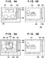
- FIGs. 5A and 5B are views showing a zoom-out action of the area zoom function.
- the camera operation screen 400 of Fig. 5A is displayed on the display unit 126.
- a captured image received from the camera server 101 is displayed in the image display region 401.
- the user inputs a drag operation 503.
- a frame 502 is displayed in accordance with the drag operation 503 by the user. This action is the same as the action described with reference to Fig. 3B .
- the zoom value icon 405 on the zoom slider 404 indicates the current zoom value.
- An estimated zoom value icon 506 indicates a zoom value when area zoom is performed based on the currently displayed frame 502. Note that the zoom value icon 405 and the estimated zoom value icon 506 are desirably displayed in different display forms so as to allow the user to distinguish them from each other. In Fig. 5A , the estimated zoom value icon 506 is a black icon such that it can be distinguished from the zoom value icon 405 by an appearance.
- a current zoom value is indicated on the left, and a zoom value when area zoom is performed in the currently displayed frame 502 is indicated on the right.
- the video camera 111 is a 10 ⁇ zoom camera
- the zoom value display region 507 indicates that current 8 ⁇ zoom is switched to 1.5 ⁇ zoom.
- Fig. 5B is the view showing the display state of the camera operation screen 400 when the zoom control of the video camera 111 ends after the user terminates the drag operation in the state of Fig. 5A .
- a captured image after the zoom-out processing is displayed in the image display region 401.
- the zoom value icon 405 is moved to a position corresponding to a zoom value after the zoom-out processing.
- the user can grasp the zoom value after area zoom by the estimated zoom value icon 506 displayed on the zoom slider 404 before determining the frame 502 at the time of area zoom. That is, the display control unit 125 displays, on the display unit 126, a display image for indicating a parameter value generated in accordance with a designation operation by the user different from the captured image before the update of the parameter value of the video camera 111 in the middle of the designation operation.
- the estimated zoom value icon 506 and the zoom value display region 507 are shown above as an example of a display image indicating the parameter value in the middle of the designation operation.
- zoom-out processing has been described with reference to Figs. 5A and 5B .
- zoom-in processing the user can also grasp the zoom value after area zoom by the displays of the zoom value display region 507 and the estimated zoom value icon 506 on the zoom slider 404 before the frame to be generated by the drag operation is determined.
- the display of the estimated zoom value icon 506 and the display of the zoom value in the zoom value display region 507 are performed simultaneously. However, one of these may be performed.
- Fig. 6 is the flowchart showing a process of controlling the display of the estimated zoom value icon 506 and the display of the zoom value display region 507. Note that the control of tilt, pan, and zoom using the tilt slider 402, the pan slider 403, and the zoom slider 404 described with reference to Figs. 4A and 4B is performed in parallel separately from the process shown in Fig. 6 .
- step S601 the command generation/interpretation unit 122 determines whether the user starts a drag operation via the operation input unit 123. If the command generation/interpretation unit 122 determines in step S601 that the drag operation is not started, step S601 is repeated until it determines that the drag operation is started.
- step S601 determines in step S601 that the drag operation is started, in step S602, it obtains and holds a frame size according to the drag operation.
- the display control unit 125 draws the frame according to the drag operation on a captured image displayed on the display unit 126.
- step S603 the command generation/interpretation unit 122 determines whether the drag operation is in a direction from the left to the right. As described with reference to Figs. 2A to 2D and Figs. 3A to 3D , whether an operation instruction is zoom-in processing or zoom-out processing is decided by the direction of each drag operation.
- the drag operation is the zoom-in processing if it includes a component in the direction from the left to the right, and is the zoom-out processing if it includes a component in the direction from the right to the left.
- the frame size obtained in step S602 and the direction of the drag operation obtained in step S603 are as described with reference to Figs. 2A to 2D and Figs. 3A to 3D .
- step S603 If the command generation/interpretation unit 122 determines in step S603 that the drag operation is in the direction from the left to the right, the zoom-in processing is performed. In this case, in step S604, the command generation/interpretation unit 122 calculates an estimated zoom value when the zoom-in processing is performed with the frame size obtained in step S602. On the other hand, if the command generation/interpretation unit 122 determines in step S603 that the drag operation is not in the direction from the left to the right, the zoom-out processing is performed. In this case, in step S605, the command generation/interpretation unit 122 calculates an estimated zoom value when the zoom-out processing is performed with the frame size obtained in step S602.
- step S606 the display control unit 125 displays a current zoom value of the video camera 111 and the estimated zoom value obtained in step S604 or step S605 in the zoom value display region 507. Subsequently, in step S607, the display control unit 125 displays the estimated zoom value icon 506 at a position corresponding to the estimated zoon value obtained in step S604 or step S605 on the zoom slider 404.
- step S608 the command generation/interpretation unit 122 determines whether the drag operation ends. If the command generation/interpretation unit 122 determines that the drag operation does not end, the process returns to step S602.
- step S608 If the command generation/interpretation unit 122 determines in step S608 that the drag operation ends, the display control unit 125 deletes the display of the zoom value display region 507 in step S609. Then, in step S610, the display control unit 125 deletes the estimated zoom value icon 506 on the zoom slider 404. In step S611, the display control unit 125 also deletes the frame 502 displayed in step S602. Subsequently, in step S612, the command generation/interpretation unit 122 generates parameter values for changing pan, tilt, and zoom of the video camera 111 in accordance with the start position and final end position of the drag operation, and sends an instruction to the camera server 101 (PTZ position designation control). Subsequently, the process returns to step S601 in which the command generation/interpretation unit 122 waits for a next drag operation.
- both the display of the zoom value display region 507 in step S606 and the display of the estimated zoom value icon 506 in step S607 are performed. However, only one of these may be performed. In this case, one of step S606 and step S607 is omitted.
- the estimated zoom value icon 506 is displayed on the zoom slider 404, and the current zoom value and the estimated zoom value are displayed in the zoom value display region 507.
- the display of an area zoon frame generated in accordance with a drag operation is further devised. More specifically, the display form of the frame is changed if a zoom state is at a zoom end or its vicinity, and zoom-in processing cannot be performed by an instructed amount, or if the zoon state is at a wide-angle end or its vicinity, and zoom-out processing cannot be performed by an instructed amount.
- This allows a user to grasp a state in which an instructed zoom operation cannot be performed due to the limit of a zoom action. That is, the user can grasp that a parameter value instructed by a designation operation exceeds a limiting value in the middle of the designation operation.
- the basic arrangement of the second embodiment is the same as in the first embodiment ( Figs. 1 and 10 ).
- a camera operation screen 400 is a screen displayed on a display unit 126.
- Fig. 7A shows an example in which the user inputs a drag operation 503 using an operation input unit 123 when a captured image is displayed in an image display region 401.
- a wide-angle end is reached in the middle of the processing. It is therefore impossible to perform zoom-out processing according to calculation based on the size of the frame 502.
- a zoom value icon 405 is displayed at a position (for example, 1.5 times) close to the lower end (the side of the wide-angle end) of a zoom slider 404.
- An estimated zoom value icon 506 is displayed at the lower end of the zoom slider 404 and indicates that an estimated zoom value based on the size of the frame 502 reaches the wide-angle end (for example, 1 time). The same also applies to a zoom value display region 507.
- the frame 502 generated in accordance with such a drag operation 503 is changed in its display form.
- the frame 502 is displayed in gray, and a display color of the frame 502 shown in Fig. 7A becomes lighter than that shown in Fig. 5A .
- Fig. 7B is a view after a video camera 111 performs a zoom action after the drag operation ends in the state of Fig. 7A .
- a captured image displayed in the image display region 401 is zoomed out a bit as compared to Fig. 7A .
- the zoom value icon 405 moves to the lower end of the zoom slider 404.
- a line indicating the frame 502 is changed from a normal color ( Fig. 5A ).
- the present invention is not limited to this. Changes in various display forms, for example, a change in type of line indicating the frame 502 from a solid line to a dotted line, a change in width of the line indicating the frame 502 to be smaller, and the like are applicable.
- Fig. 8A shows an example in which the user performs the drag operation 503 for zoom-out processing for a captured image via the operation input unit 123 when the captured image is displayed in the image display region 401.
- the zoom value icon 405 on the zoom slider 404 is displayed at the wide-angle end of the zoom slider 404.
- the frame 502 is displayed by the dotted line as shown in Fig. 8A and with a line having a color much lighter than that of the frame 502 in Fig. 7A . This is to inform the user that the zoom-out processing cannot be performed at all. Only x1.0 indicating 1 time of a current magnification only is displayed in a zoom value display area.
- Fig. 8B is a view after the drag operation ends in the state of Fig. 8A .
- a captured image displayed in the image display region 401 is the same as the captured image displayed in Fig. 8A . This is because the zoom state has already reached the wide-angle end, and thus the zoom-out processing cannot be performed anymore. However, if the center position of the frame 502 moves from the center position of the captured image, movement in pan and tilt directions by that moving amount is performed.
- the frame 502 is displayed by the dotted line and in a light color, and the zoom value display region 507 is displayed in a light color.
- the present invention is not limited to this.
- the frame 502 may not be displayed, the line thickness of the frame 502 may be changed (decreased), or the like.
- Figs. 9A and 9B are the flowcharts for explaining a process of an area zoom function, and show a process of changing the display form of the frame 502 as shown in Figs. 5A and 5B , Figs. 7A and 7B, and Figs. 8A and 8B in accordance with respective conditions.
- the color of the zoom value display area is also changed by the color of the frame decided here.
- step S900 a command generation/interpretation unit 122 determines whether a drag operation by the user is started. If the command generation/interpretation unit 122 determines in step S900 that the drag operation is not started, step S900 is repeated until it determines that the drag operation is started. If the command generation/interpretation unit 122 determines in step S900 that drag is started, it obtains a current zoom value in step S901. Then, in step S902, the command generation/interpretation unit 122 obtains a start position of the drag operation. Then, in step S903, the command generation/interpretation unit 122 obtains a current position of the drag operation (for example, a current position of a mouse).
- a current position of the drag operation for example, a current position of a mouse.
- step S904 the command generation/interpretation unit 122 determines whether drag is in a direction from the left to the right from the start position of the drag operation obtained in step S902 and the current position of the drag operation obtained in step S903. If the command generation/interpretation unit 122 determines in step S904 that the drag operation is in the direction from the left to the right, it determines that zoom-in processing is instructed. In this case, the process advances to step S905 in which the command generation/interpretation unit 122 determines whether the current zoom value obtained in step S901 is at a zoom end. If the command generation/interpretation unit 122 determines that the current zoom value is at the zoom end, the process advances to step S906 in which it decides a display color (frame color) to be light gray.
- step S907 the command generation/interpretation unit 122 calculates an estimated zoom value when a zoom-in action according to the drag operation at the start position obtained in step S902 and the end position obtained in step S903 is performed. Then, in step S908, the command generation/interpretation unit 122 determines whether the estimated zoom value is at a zoom end. If the command generation/interpretation unit 122 determines that the estimated zoom value is at the zoom end, the process advances to step S910 in which it decides the frame color to be gray. If the command generation/interpretation unit 122 determines in step S908 that the estimated zoom value is not at the zoom end, the process advances to step S909 in which it sets the frame color to black.
- step S904 if the command generation/interpretation unit 122 determines that the drag operation is not in the direction from the left to the right, it determines that zoom-out processing is instructed. In this case, the process advances to step S911 in which the command generation/interpretation unit 122 determines whether the current zoom value obtained in step S901 is at a wide-angle end. If the command generation/interpretation unit 122 determines that the current zoom value is at the wide-angle end, the process advances to step S912 in which it decides the display color (frame color) to be light gray.
- step S913 the command generation/interpretation unit 122 calculates an estimated zoom value when a zoom-out action according to the drag operation at the start position obtained in step S902 and the end position obtained in step S903 is performed. Then, in step S914, the command generation/interpretation unit 122 determines whether the estimated zoom value is at the wide-angle end. If the command generation/interpretation unit 122 determines that the estimated zoom value is at the wide-angle end, the process advances to step S910 in which it decides the frame color to be gray. On the other hand, if the command generation/interpretation unit 122 determines in step S914 that the estimated zoom value is not at the wide-angle end, the process advances to step S915 in which it decides the frame color to be black.
- a display control unit 125 displays the frame 502 on the display unit 126 in accordance with the color decided in step S906, S909, S910, S912, or S915. Then, in step S917, the display control unit 125 displays the estimated zoom value icon 506 at the position of the estimated zoom value on the zoom slider 404, and displays the current zoom value and the estimated zoom value in the zoom value display region 507.
- the display control unit 125 uses the color decided for the frame as the display color of the zoom value display region 507. Note that the color of the estimated zoom value icon 506 may be changed by using the color decided for the frame.
- step S918 the command generation/interpretation unit 122 determines whether the drag operation ends. If the command generation/interpretation unit 122 determines that the drag operation does not end, the process returns to step S903. If the command generation/interpretation unit 122 determines in step S918 that drag ends, the process advances to step S919 in which the display control unit 125 deletes the frame 502 displayed in step S916. In step S920, the display control unit 125 also deletes the estimated zoom value icon 506 and zoom value display region 507 displayed in step S917.
- step S921 the command generation/interpretation unit 122 generates a command to change pan, tilt, and zoom of the video camera 111 in accordance with the start position and final end position of the drag operation obtained in steps S902 and S903.
- the command generation/interpretation unit 122 sends the generated command to a camera server 101 (PTZ position designation control). Subsequently, the process returns to step S900 in which the command generation/interpretation unit 122 waits for a next drag operation.
- the user can easily grasp that the zoom action reaches its limit in the middle of designating the action by designating the region of a captured image, making it impossible to perform zoom-out processing according to the designated region.
- a zoom position when control corresponding to a region being selected by the user is performed is displayed to the user simply.
- An action to be different from a normal one can also be displayed to the user simply if it is estimated that a desired action is not obtained because a zoom end or a wide-angle end is reached before the control corresponding to the region is complete.
- Embodiment(s) of the present invention can also be realized by a computer of a system or apparatus that reads out and executes computer executable instructions (e.g., one or more programs) recorded on a storage medium (which may also be referred to more fully as a 'non-transitory computer-readable storage medium') to perform the functions of one or more of the above-described embodiment(s) and/or that includes one or more circuits (e.g., application specific integrated circuit (ASIC)) for performing the functions of one or more of the above-described embodiment(s), and by a method performed by the computer of the system or apparatus by, for example, reading out and executing the computer executable instructions from the storage medium to perform the functions of one or more of the above-described embodiment(s) and/or controlling the one or more circuits to perform the functions of one or more of the above-described embodiment(s).
- computer executable instructions e.g., one or more programs
- a storage medium which may also be referred to more fully as
- the computer may comprise one or more processors (e.g., central processing unit (CPU), micro processing unit (MPU)) and may include a network of separate computers or separate processors to read out and execute the computer executable instructions.
- the computer executable instructions may be provided to the computer, for example, from a network or the storage medium.
- the storage medium may include, for example, one or more of a hard disk, a random-access memory (RAM), a read only memory (ROM), a storage of distributed computing systems, an optical disk (such as a compact disc (CD), digital versatile disc (DVD), or Blu-ray Disc (BD)TM), a flash memory device, a memory card, and the like.
- An image capturing control apparatus controls, in accordance with an end of an operation by a user on an image captured by an image capture apparatus, a parameter value according to the operation to be set in the image capture apparatus, and causes a display unit to display a display image which indicates the parameter value according to the operation and is different from the captured image.
- the display unit is caused to display the display image corresponding to the parameter value according to the operation at the first time point.
Abstract
Description
- The present invention relates to an image capturing control apparatus that controls a parameter setting to an image capture apparatus, a method of controlling the same and a computer program for causing a computer to perform the method.
- One example of control of a network camera includes an area zoom function of zooming in on an area designated by a user on a displayed video. In the area zoom function, pan and tilt area controlled such that the center of the designated area matches the center of a video shot by a camera, and zoom control is performed so as to display the designated area large. A zoom magnification at this time is decided based on the ratio of the size of the area designated by the user and the size of a currently displayed video.
- Japanese Patent Laid-Open No.
2004-157869 2004-157869 - In a technique disclosed in Japanese Patent Laid-Open No.
2004-157869 - When the action of an apparatus is controlled by an operation performed on a captured image, the following embodiment allows a user to grasp that control state more easily.
- The present invention in its first aspect provides an image capturing control apparatus as specified in
claims 1 to 11. - The present invention in its second aspect provides a method of controlling an image capturing control apparatus as specified in
claim 12. - The present invention in its third aspect provides a computer program as specified in
claim 13. - Further features of the present invention will become apparent from the following description of exemplary embodiments (with reference to the attached drawings).
-
-
Fig. 1 is a block diagram showing a network camera system according to an embodiment; -
Figs. 2A to 2D are views for explaining an area zoom (zoom-in) function; -
Figs. 3A to 3D are views for explaining an area zoom (zoom-out) function; -
Figs. 4A and 4B are views for explaining zoom sliders according to the embodiment; -
Figs. 5A and 5B are views each for explaining display at the time of zoom-out processing according to the embodiment; -
Fig. 6 is a flowchart showing area zoom processing according to the first embodiment; -
Figs. 7A and 7B are views each for explaining display at the time of zoom-out processing in a zoom state close to a wide-angle end; -
Figs. 8A and 8B are views each for explaining display at the time of the zoom-out processing when zoom is at the wide-angle end; -
Figs. 9A and9B are flowcharts showing area zoom processing according to the second embodiment; and -
Fig. 10 is a block diagram showing an example of the hardware arrangement of a network camera system. - Embodiments of the present invention will be described in detail below with reference to the accompanying drawings. Note that a parameter value (zoom magnification) related to a zoom action of an image capture apparatus is exemplified as a parameter value set in the image capture apparatus in accordance with designation of a partial region for a captured image below. However, the present invention is not limited to this.
-
Fig. 1 is a block diagram showing an example of the arrangement of a network camera system according to the first embodiment. In the network camera system ofFig. 1 , acamera server 101 delivers live video information from avideo camera 111 via a network. Aviewer client 102 displays a video transmitted from thecamera server 101 on adisplay unit 126. Theviewer client 102 also provides a user with a user interface for ordering a shooting position (pan, tilt, and zoom) for thevideo camera 111, and functions as an image capturing control apparatus. Thecamera server 101 and theviewer client 102 are connected by anetwork 103 capable of IP-based communication such as a LAN or the Internet. Note that thevideo camera 111 is used in this embodiment. However, a camera that performs still image shooting may be used. Therefore, the video and still image captured by the camera will generally be referred to as captured images below. - Note that the
network 103 can be any digital network such as the Internet or an intranet having a band enough to pass a camera control signal and compressed image signal to be described later. In this embodiment, assume that the TCP/IP (UDP/IP) protocol is used as a network protocol of thenetwork 103. Thus, an address indicates an IP address below. Moreover, IP addresses are assigned to all thecamera server 101 andviewer client 102. - In accordance with a command received from the
viewer client 102 by acommunication control unit 114, thecamera server 101 distributes image data via thenetwork 103 and performs various camera operations and the like. Animage input unit 115 receives an image (captured image) captured by thevideo camera 111. A moving image of 30 fps can be obtained if images of 30 frames/sec are obtained. Animage compression unit 116 compresses the captured image obtained by theimage input unit 115 into a data size which is distributed to a client easily. For example, theimage compression unit 116 receives an NTSC image signal from thevideo camera 111, A/D-converts and then compresses this, and transfers the A/D converted signal to thecommunication control unit 114. Thecommunication control unit 114 sends this compressed captured image to thenetwork 103. Astorage unit 118 holds various setting values and data. - The
video camera 111 is attached to amovable camera platform 112. Acommand interpretation unit 117 interprets an operation command received from theviewer client 102 by thecommunication control unit 114. A camera/cameraplatform control unit 113 controls themovable camera platform 112 in accordance with control contents interpreted by the operation command by thecommand interpretation unit 117, controlling a pan angle and tilt angle of thevideo camera 111. The camera/cameraplatform control unit 113 also controls a zoom magnification and various image quality settings of thevideo camera 111 in accordance with the control contents interpreted by thecommand interpretation unit 117. - The
viewer client 102 is connected to thecamera server 101 by designating the IP address assigned to thecamera server 101. Acommunication control unit 121 receives a captured image transmitted (compressed) from thecamera server 101 and a panoramic image held by thestorage unit 118. Thecommunication control unit 121 also receives results of the various camera operations. - A
display control unit 125 displays a captured image and panoramic image decompressed by animage decompression unit 124 on thedisplay unit 126. Thedisplay control unit 125 also generates a graphical user interface (GUI) from the results of the various camera operations and displays it on thedisplay unit 126. Thedisplay unit 126 is a display device such as a display. If a plurality of network cameras (video cameras 111) are connected, it is possible to display captured images from the plurality of network cameras or to select the captured image of one camera. - An
operation input unit 123 includes a keyboard, or a pointing device such as a mouse or a touch panel. The user can input an operation for changing parameter values of thevideo camera 111 andmovable camera platform 112 by using theoperation input unit 123. A command generation/interpretation unit 122 generates various camera operation commands from a GUI operation input via theoperation input unit 123. The generated camera operation commands are transmitted from thecommunication control unit 121 to thecamera server 101 via thenetwork 103. The command generation/interpretation unit 122 also interprets a camera operation result received from thecamera server 101 and transfers it to thedisplay control unit 125. - Hardware arrangements needed in the
camera server 101 andviewer client 102 are the same as in a general PC, allowing them to be implemented as software that operates on the general PC. Note that in this embodiment, onecamera server 101 and oneviewer client 102 are used for the sake of descriptive simplicity. However, there is no limitation on the numbers of connected camera servers and viewer clients. For example, a plurality ofcamera servers 101 may be connected to oneviewer client 102. Further, thevideo camera 111 and themovable camera platform 112 may be connected to thecamera server 101 via the network. Furthermore, thecamera server 101 and theviewer client 102 may be implemented by one information processing apparatus. -
Fig. 10 is a block diagram showing an example of the hardware arrangement of a network camera system. In thecamera server 101, aCPU 201 implements various kinds of control of thecamera server 101 by executing programs stored in aROM 202 or aRAM 203. For example, theCPU 201 executes a predetermined program, implementing theimage compression unit 116 and thecommand interpretation unit 117. - The
ROM 202 is a read-only memory. TheRAM 203 is a memory capable of read and write as needed. Asecondary storage device 204 is a large-capacity storage device such as a hard disk or the like. TheCPU 201 implements thestorage unit 118 by using theRAM 203 and thesecondary storage device 204. Anetwork interface 205 is connected to thenetwork 103, and implements communication between thecamera server 101 and thenetwork 103. TheCPU 201 implements thecommunication control unit 114 by using thenetwork interface 205. Acamera interface 206 is connected to thevideo camera 111 and themovable camera platform 112. TheCPU 201 implements theimage input unit 115 and the camera/cameraplatform control unit 113 by using thecamera interface 206. The above-described respective arrangements are connected to be communicable with each other by abus 207. - In the
viewer client 102, aCPU 211 implements various kinds of control of theviewer client 102 by executing programs stored in aROM 212 or aRAM 213. For example, theCPU 211 executes a predetermined program, implementing theimage decompression unit 124, thedisplay control unit 125, and the command generation/interpretation unit 122. TheROM 212 is a read-only memory. TheRAM 213 is a memory capable of read and write as needed. Asecondary storage device 214 is a large-capacity storage device such as a hard disk or the like. Anetwork interface 215 is connected to thenetwork 103, and implements communication between theviewer client 102 and thenetwork 103. TheCPU 211 implements thecommunication control unit 121 by using thenetwork interface 215. Theoperation input unit 123, thedisplay unit 126, and the above-described respective arrangements are connected to be communicable with each other by abus 217. - A designation operation and zoom action of the user in zoom-in processing by an area zoom function will be described next with reference to
Figs. 2A to 2D. Fig. 2A is a display example of a captured image on thedisplay unit 126. The image captured by thevideo camera 111 is displayed on ascreen 10.Fig. 2B shows an example of a state in which the user performs a drag operation on thescreen 10 via theoperation input unit 123 in the situation ofFig. 2A . The drag operation is an example of a designation operation by the user. In accordance with adrag operation 12 by the user, aframe 11 indicating a partial region of the captured image is displayed.Fig. 2C shows an example when drag operations end in the state ofFig. 2B . Thedrag operation 12 is in a direction that moves toward the right on the captured image, and thus interpreted as a zoom-in instruction. Theviewer client 102 controls thevideo camera 111 such that aframe 13 generated by thedrag operation 12 becomes a next angle of view.Fig. 2D shows a state after the zoom control of thevideo camera 111 is performed in accordance with theframe 13. As described above, in the zoom-in processing in the area zoom function, the portion of theframe 13 generated inFig. 2C becomes the angle of view. - Note that a region indicated by the
frame 13 becomes the angle of view, and thus the aspect ratio of a rectangle indicated by theframe 13 matches that of the captured image. In this embodiment, theframe 13 is decided and drawn using a long side of the rectangle having a line that connects the start point and end point of each drag operation as a diagonal line. Theframe 13 is also drawn at a position where the start point of each drag operation and a corresponding one of angles of theframe 13 match. - A designation operation and zoom action of the user in zoom-out processing by the area zoom function will be described next with reference to
Figs. 3A to 3D. Fig. 3A is a display example of a captured image on thedisplay unit 126. The image captured by thevideo camera 111 is displayed on a screen 20.Fig. 3B shows a state in which the user performs a drag operation on the screen 20 via theoperation input unit 123 in the situation ofFig. 3A . Aframe 21 is displayed in accordance with adrag operation 22.Fig. 3C shows an example when drag operations end in the state ofFig. 3B . Thedrag operation 22 is in a direction that moves toward the left on the captured image, and thus interpreted as a zoom-out instruction. Thevideo camera 111 is controlled such that a current angle of view falls within a generatedframe 23.Fig. 3D shows a state after the zoom control (zoom-out) of thevideo camera 111 is performed in accordance with theframe 23. Referring toFig. 3D , the angle of view at the time ofFig. 3C falls within a portion selected in the frame generated inFig. 3C . Note that the aspect ratio and drawing position of theframe 23 are the same as theframe 13. In addition to a zoom change described above, the tilt and pan directions of thevideo camera 111 are also changed such that the center position of theframe 13 orframe 23 becomes the center position of the captured image. - As described above, in the zoom-in processing (
Figs. 2A to 2D ) of the area zoom function, theframe 13 set in accordance with the user designation operation becomes the next angle of view, allowing the user to intuitionally grasp a state after execution of the zoom-in processing. In the case of the zoom-out processing, however, it is difficult to intuitionally grasp the degree of the zoom-out processing, as shown inFigs. 3C and 3D . -
Figs. 4A and 4B are views each representing an example of a screen displayed on thedisplay unit 126 of theviewer client 102 to which the user interface is applied according to this embodiment. - A
camera operation screen 400 shown in each ofFigs. 4A and 4B is displayed on thedisplay unit 126. On thecamera operation screen 400, a captured image received from thecamera server 101 is displayed in animage display region 401. In addition, atilt slider 402,pan slider 403, andzoom slider 404 for changing parameter values set in the image capture apparatus (thevideo camera 111 and the movable camera platform 112) are displayed on thecamera operation screen 400 as operation images different from the captured image. The user can control the tilt, pan, and zoom of thevideo camera 111 by operating thetilt slider 402, thepan slider 403, and thezoom slider 404. On thezoom slider 404, a current zoom value of thevideo camera 111 is indicated by azoom value icon 405. A telephoto state is obtained as thezoom value icon 405 moves upward on thezoom slider 404, and a wide angle is obtained as thezoom value icon 405 moves downward. The user can control tilt, pan, or zoom by clicking on thetilt slider 402, thepan slider 403, or thezoom slider 404. -
Fig. 4B is the view showing the display state of thecamera operation screen 400 when aposition 406 on thezoom slider 404 is clicked in the state ofFig. 4A , and the zoom control of thevideo camera 111 according to this ends. On thezoom slider 404, thezoom value icon 405 indicating a current zoom state moves to the position 406 (Fig. 4A ) clicked on thezoom slider 404. In accordance with this, the captured image in theimage display region 401 is switched to a wide-angle image. Thezoom value icon 405 of thezoom slider 404 thus represents the current zoom value by its display position. - Note that the same operation can also be performed on the
tilt slider 402 and thepan slider 403. That is, if a desired position of thetilt slider 402 is clicked, themovable camera platform 112 changes the tilt direction of thevideo camera 111 in accordance with the clicked position. If a desired position of thepan slider 403 is clicked, themovable camera platform 112 changes the pan direction of thevideo camera 111 in accordance with the clicked position. - Zoom-out processing in the area zoom function of this embodiment will be described next with reference to
Figs. 5A and 5B. Figs. 5A and 5B are views showing a zoom-out action of the area zoom function. Thecamera operation screen 400 ofFig. 5A is displayed on thedisplay unit 126. A captured image received from thecamera server 101 is displayed in theimage display region 401. InFig. 5A , the user inputs adrag operation 503. Aframe 502 is displayed in accordance with thedrag operation 503 by the user. This action is the same as the action described with reference toFig. 3B . As described with reference toFig. 4A , thezoom value icon 405 on thezoom slider 404 indicates the current zoom value. An estimatedzoom value icon 506 indicates a zoom value when area zoom is performed based on the currently displayedframe 502. Note that thezoom value icon 405 and the estimatedzoom value icon 506 are desirably displayed in different display forms so as to allow the user to distinguish them from each other. InFig. 5A , the estimatedzoom value icon 506 is a black icon such that it can be distinguished from thezoom value icon 405 by an appearance. - In a zoom
value display region 507, a current zoom value is indicated on the left, and a zoom value when area zoom is performed in the currently displayedframe 502 is indicated on the right. For example, thevideo camera 111 is a 10× zoom camera, and the zoomvalue display region 507 indicates that current 8× zoom is switched to 1.5× zoom.Fig. 5B is the view showing the display state of thecamera operation screen 400 when the zoom control of thevideo camera 111 ends after the user terminates the drag operation in the state ofFig. 5A . A captured image after the zoom-out processing is displayed in theimage display region 401. Thezoom value icon 405 is moved to a position corresponding to a zoom value after the zoom-out processing. As described above, in this embodiment, the user can grasp the zoom value after area zoom by the estimatedzoom value icon 506 displayed on thezoom slider 404 before determining theframe 502 at the time of area zoom. That is, thedisplay control unit 125 displays, on thedisplay unit 126, a display image for indicating a parameter value generated in accordance with a designation operation by the user different from the captured image before the update of the parameter value of thevideo camera 111 in the middle of the designation operation. The estimatedzoom value icon 506 and the zoomvalue display region 507 are shown above as an example of a display image indicating the parameter value in the middle of the designation operation. - Note that the zoom-out processing has been described with reference to
Figs. 5A and 5B . However, the same also applies to the case of zoom-in processing. That is, in a zoom-in operation, the user can also grasp the zoom value after area zoom by the displays of the zoomvalue display region 507 and the estimatedzoom value icon 506 on thezoom slider 404 before the frame to be generated by the drag operation is determined. In this embodiment, the display of the estimatedzoom value icon 506 and the display of the zoom value in the zoomvalue display region 507 are performed simultaneously. However, one of these may be performed. - Processing in the first embodiment will be described next with reference to a flowchart of
Fig. 6. Fig. 6 is the flowchart showing a process of controlling the display of the estimatedzoom value icon 506 and the display of the zoomvalue display region 507. Note that the control of tilt, pan, and zoom using thetilt slider 402, thepan slider 403, and thezoom slider 404 described with reference toFigs. 4A and 4B is performed in parallel separately from the process shown inFig. 6 . - The control shown in
Fig. 6 starts in a state in which thecamera operation screen 400 shown inFig. 4A is displayed. First, in step S601, the command generation/interpretation unit 122 determines whether the user starts a drag operation via theoperation input unit 123. If the command generation/interpretation unit 122 determines in step S601 that the drag operation is not started, step S601 is repeated until it determines that the drag operation is started. - If the command generation/
interpretation unit 122 determines in step S601 that the drag operation is started, in step S602, it obtains and holds a frame size according to the drag operation. Thedisplay control unit 125 draws the frame according to the drag operation on a captured image displayed on thedisplay unit 126. Subsequently, in step S603, the command generation/interpretation unit 122 determines whether the drag operation is in a direction from the left to the right. As described with reference toFigs. 2A to 2D andFigs. 3A to 3D , whether an operation instruction is zoom-in processing or zoom-out processing is decided by the direction of each drag operation. In this embodiment, it is decided that the drag operation is the zoom-in processing if it includes a component in the direction from the left to the right, and is the zoom-out processing if it includes a component in the direction from the right to the left. Note that the frame size obtained in step S602 and the direction of the drag operation obtained in step S603 are as described with reference toFigs. 2A to 2D andFigs. 3A to 3D . - If the command generation/
interpretation unit 122 determines in step S603 that the drag operation is in the direction from the left to the right, the zoom-in processing is performed. In this case, in step S604, the command generation/interpretation unit 122 calculates an estimated zoom value when the zoom-in processing is performed with the frame size obtained in step S602. On the other hand, if the command generation/interpretation unit 122 determines in step S603 that the drag operation is not in the direction from the left to the right, the zoom-out processing is performed. In this case, in step S605, the command generation/interpretation unit 122 calculates an estimated zoom value when the zoom-out processing is performed with the frame size obtained in step S602. - When step S604 or step S605 ends, in step S606, the
display control unit 125 displays a current zoom value of thevideo camera 111 and the estimated zoom value obtained in step S604 or step S605 in the zoomvalue display region 507. Subsequently, in step S607, thedisplay control unit 125 displays the estimatedzoom value icon 506 at a position corresponding to the estimated zoon value obtained in step S604 or step S605 on thezoom slider 404. In step S608, the command generation/interpretation unit 122 determines whether the drag operation ends. If the command generation/interpretation unit 122 determines that the drag operation does not end, the process returns to step S602. - If the command generation/
interpretation unit 122 determines in step S608 that the drag operation ends, thedisplay control unit 125 deletes the display of the zoomvalue display region 507 in step S609. Then, in step S610, thedisplay control unit 125 deletes the estimatedzoom value icon 506 on thezoom slider 404. In step S611, thedisplay control unit 125 also deletes theframe 502 displayed in step S602. Subsequently, in step S612, the command generation/interpretation unit 122 generates parameter values for changing pan, tilt, and zoom of thevideo camera 111 in accordance with the start position and final end position of the drag operation, and sends an instruction to the camera server 101 (PTZ position designation control). Subsequently, the process returns to step S601 in which the command generation/interpretation unit 122 waits for a next drag operation. - Note that in this embodiment, both the display of the zoom
value display region 507 in step S606 and the display of the estimatedzoom value icon 506 in step S607 are performed. However, only one of these may be performed. In this case, one of step S606 and step S607 is omitted. - As described above, according to the first embodiment, when the area zoom function is used, the estimated
zoom value icon 506 is displayed on thezoom slider 404, and the current zoom value and the estimated zoom value are displayed in the zoomvalue display region 507. By performing such display regarding the estimated zoom value, a problem that the zoom action of the area zoom function, in particular, at the time of zoom-out processing is difficult to understand is solved, making it possible to notify the user of the zoom action simply. This allows the user to grasp the degree of zoom at a glance when selecting an area (frame), improving usability of area zoom. - In the first embodiment, the arrangement for improving convenience of area zoom by notifying the user of the estimated zoom value has been described. In the second embodiment, the display of an area zoon frame generated in accordance with a drag operation is further devised. More specifically, the display form of the frame is changed if a zoom state is at a zoom end or its vicinity, and zoom-in processing cannot be performed by an instructed amount, or if the zoon state is at a wide-angle end or its vicinity, and zoom-out processing cannot be performed by an instructed amount. This allows a user to grasp a state in which an instructed zoom operation cannot be performed due to the limit of a zoom action. That is, the user can grasp that a parameter value instructed by a designation operation exceeds a limiting value in the middle of the designation operation. The basic arrangement of the second embodiment is the same as in the first embodiment (
Figs. 1 and10 ). - Zoom frame display in the second embodiment will be described with reference to
Figs. 7A and 7B . InFig. 7A , acamera operation screen 400 is a screen displayed on adisplay unit 126.Fig. 7A shows an example in which the user inputs adrag operation 503 using anoperation input unit 123 when a captured image is displayed in animage display region 401. In this example, even if the user tries to perform zoom-out processing based on aframe 502 having a size designated by thedrag operation 503, a wide-angle end is reached in the middle of the processing. It is therefore impossible to perform zoom-out processing according to calculation based on the size of theframe 502. Azoom value icon 405 is displayed at a position (for example, 1.5 times) close to the lower end (the side of the wide-angle end) of azoom slider 404. An estimatedzoom value icon 506 is displayed at the lower end of thezoom slider 404 and indicates that an estimated zoom value based on the size of theframe 502 reaches the wide-angle end (for example, 1 time). The same also applies to a zoomvalue display region 507. - As described above, if the zoon action designated by the
drag operation 503 exceeds the limit of the zoom action, theframe 502 generated in accordance with such adrag operation 503 is changed in its display form. In this embodiment, theframe 502 is displayed in gray, and a display color of theframe 502 shown inFig. 7A becomes lighter than that shown inFig. 5A . By thus making the display form of theframe 502 different from a normal one, it is possible to indicate to the user that the display form is different from the normal one. Note that the color of the zoomvalue display region 507 is also displayed in gray in accordance with this. -
Fig. 7B is a view after avideo camera 111 performs a zoom action after the drag operation ends in the state ofFig. 7A . A captured image displayed in theimage display region 401 is zoomed out a bit as compared toFig. 7A . Thezoom value icon 405 moves to the lower end of thezoom slider 404. - Note that processing in a case in which the zoom-out processing according to the frame designated by the user cannot be performed because the wide-angle end is reached in the middle of designating the zoom-out processing has been described with reference to
Figs. 7A and 7B . The same also applies to processing in a case in which zoom-in processing according to a frame designated by the user cannot be performed because a zoom end is reached in the middle of designating the zoom-in processing. In this embodiment, the color of a line indicating theframe 502 is changed from a normal color (Fig. 5A ). However, the present invention is not limited to this. Changes in various display forms, for example, a change in type of line indicating theframe 502 from a solid line to a dotted line, a change in width of the line indicating theframe 502 to be smaller, and the like are applicable. - Processing regarding frame display in the second embodiment will further be described with reference to
Figs. 8A and 8B . A case in which a drag operation for further zooming out on an image in a state in which an angle of view has already reached a wide-angle end will be described with reference toFigs. 8A and 8B . -
Fig. 8A shows an example in which the user performs thedrag operation 503 for zoom-out processing for a captured image via theoperation input unit 123 when the captured image is displayed in theimage display region 401. In this example, since the angle of view has already reached the wide-angle end, the zoom-out processing cannot be performed anymore even if the user tries to perform it. Thezoom value icon 405 on thezoom slider 404 is displayed at the wide-angle end of thezoom slider 404. Theframe 502 is displayed by the dotted line as shown inFig. 8A and with a line having a color much lighter than that of theframe 502 inFig. 7A . This is to inform the user that the zoom-out processing cannot be performed at all. Only x1.0 indicating 1 time of a current magnification only is displayed in a zoom value display area. -
Fig. 8B is a view after the drag operation ends in the state ofFig. 8A . A captured image displayed in theimage display region 401 is the same as the captured image displayed inFig. 8A . This is because the zoom state has already reached the wide-angle end, and thus the zoom-out processing cannot be performed anymore. However, if the center position of theframe 502 moves from the center position of the captured image, movement in pan and tilt directions by that moving amount is performed. - Note that the processing in the case in which the zoom-out processing cannot be performed because the zoom state has already reached the wide-angle end at the time of zoom-out designation has been described with reference to
Figs. 8A and 8B . However, the same processing is also obtained in a case in which zoom-in processing cannot be performed because the zoon state has already reached the zoom end at the time of zoom-in designation. In the second embodiment, theframe 502 is displayed by the dotted line and in a light color, and the zoomvalue display region 507 is displayed in a light color. However, the present invention is not limited to this. For example, theframe 502 may not be displayed, the line thickness of theframe 502 may be changed (decreased), or the like. - Processing of the second embodiment will be described next with reference to flowcharts of
Figs. 9A and9B .Figs. 9A and9B are the flowcharts for explaining a process of an area zoom function, and show a process of changing the display form of theframe 502 as shown inFigs. 5A and 5B ,Figs. 7A and 7B, and Figs. 8A and 8B in accordance with respective conditions. As can be seen from the zoomvalue display region 507 shown in each ofFigs. 5A and 5B ,Figs. 7A and 7B, and Figs. 8A and 8B , the color of the zoom value display area is also changed by the color of the frame decided here. - When the process shown in
Figs. 9A and9B starts, first, in step S900, a command generation/interpretation unit 122 determines whether a drag operation by the user is started. If the command generation/interpretation unit 122 determines in step S900 that the drag operation is not started, step S900 is repeated until it determines that the drag operation is started. If the command generation/interpretation unit 122 determines in step S900 that drag is started, it obtains a current zoom value in step S901. Then, in step S902, the command generation/interpretation unit 122 obtains a start position of the drag operation. Then, in step S903, the command generation/interpretation unit 122 obtains a current position of the drag operation (for example, a current position of a mouse). - In step S904, the command generation/
interpretation unit 122 determines whether drag is in a direction from the left to the right from the start position of the drag operation obtained in step S902 and the current position of the drag operation obtained in step S903. If the command generation/interpretation unit 122 determines in step S904 that the drag operation is in the direction from the left to the right, it determines that zoom-in processing is instructed. In this case, the process advances to step S905 in which the command generation/interpretation unit 122 determines whether the current zoom value obtained in step S901 is at a zoom end. If the command generation/interpretation unit 122 determines that the current zoom value is at the zoom end, the process advances to step S906 in which it decides a display color (frame color) to be light gray. - If the command generation/
interpretation unit 122 determines in step S905 that the current zoom value is not at the zoom end, the process advances to step S907. In step S907, the command generation/interpretation unit 122 calculates an estimated zoom value when a zoom-in action according to the drag operation at the start position obtained in step S902 and the end position obtained in step S903 is performed. Then, in step S908, the command generation/interpretation unit 122 determines whether the estimated zoom value is at a zoom end. If the command generation/interpretation unit 122 determines that the estimated zoom value is at the zoom end, the process advances to step S910 in which it decides the frame color to be gray. If the command generation/interpretation unit 122 determines in step S908 that the estimated zoom value is not at the zoom end, the process advances to step S909 in which it sets the frame color to black. - On the other hand, in step S904, if the command generation/
interpretation unit 122 determines that the drag operation is not in the direction from the left to the right, it determines that zoom-out processing is instructed. In this case, the process advances to step S911 in which the command generation/interpretation unit 122 determines whether the current zoom value obtained in step S901 is at a wide-angle end. If the command generation/interpretation unit 122 determines that the current zoom value is at the wide-angle end, the process advances to step S912 in which it decides the display color (frame color) to be light gray. - If the command generation/
interpretation unit 122 determines in step S911 that the current zoom value is not at the wide-angle end, the process advances to step S913. In step S913, the command generation/interpretation unit 122 calculates an estimated zoom value when a zoom-out action according to the drag operation at the start position obtained in step S902 and the end position obtained in step S903 is performed. Then, in step S914, the command generation/interpretation unit 122 determines whether the estimated zoom value is at the wide-angle end. If the command generation/interpretation unit 122 determines that the estimated zoom value is at the wide-angle end, the process advances to step S910 in which it decides the frame color to be gray. On the other hand, if the command generation/interpretation unit 122 determines in step S914 that the estimated zoom value is not at the wide-angle end, the process advances to step S915 in which it decides the frame color to be black. - In step S916, a
display control unit 125 displays theframe 502 on thedisplay unit 126 in accordance with the color decided in step S906, S909, S910, S912, or S915. Then, in step S917, thedisplay control unit 125 displays the estimatedzoom value icon 506 at the position of the estimated zoom value on thezoom slider 404, and displays the current zoom value and the estimated zoom value in the zoomvalue display region 507. Thedisplay control unit 125 uses the color decided for the frame as the display color of the zoomvalue display region 507. Note that the color of the estimatedzoom value icon 506 may be changed by using the color decided for the frame. - Then, in step S918, the command generation/
interpretation unit 122 determines whether the drag operation ends. If the command generation/interpretation unit 122 determines that the drag operation does not end, the process returns to step S903. If the command generation/interpretation unit 122 determines in step S918 that drag ends, the process advances to step S919 in which thedisplay control unit 125 deletes theframe 502 displayed in step S916. In step S920, thedisplay control unit 125 also deletes the estimatedzoom value icon 506 and zoomvalue display region 507 displayed in step S917. Then, in step S921, the command generation/interpretation unit 122 generates a command to change pan, tilt, and zoom of thevideo camera 111 in accordance with the start position and final end position of the drag operation obtained in steps S902 and S903. The command generation/interpretation unit 122 sends the generated command to a camera server 101 (PTZ position designation control). Subsequently, the process returns to step S900 in which the command generation/interpretation unit 122 waits for a next drag operation. - As described above, in a network camera system of the second embodiment, the user can easily grasp that the zoom action reaches its limit in the middle of designating the action by designating the region of a captured image, making it impossible to perform zoom-out processing according to the designated region.
- As described above, according to the above embodiments, in area zoom that instructs the zoom action by designating the region of the captured image, a zoom position when control corresponding to a region being selected by the user is performed is displayed to the user simply. An action to be different from a normal one can also be displayed to the user simply if it is estimated that a desired action is not obtained because a zoom end or a wide-angle end is reached before the control corresponding to the region is complete.
- Embodiment(s) of the present invention can also be realized by a computer of a system or apparatus that reads out and executes computer executable instructions (e.g., one or more programs) recorded on a storage medium (which may also be referred to more fully as a 'non-transitory computer-readable storage medium') to perform the functions of one or more of the above-described embodiment(s) and/or that includes one or more circuits (e.g., application specific integrated circuit (ASIC)) for performing the functions of one or more of the above-described embodiment(s), and by a method performed by the computer of the system or apparatus by, for example, reading out and executing the computer executable instructions from the storage medium to perform the functions of one or more of the above-described embodiment(s) and/or controlling the one or more circuits to perform the functions of one or more of the above-described embodiment(s). The computer may comprise one or more processors (e.g., central processing unit (CPU), micro processing unit (MPU)) and may include a network of separate computers or separate processors to read out and execute the computer executable instructions. The computer executable instructions may be provided to the computer, for example, from a network or the storage medium. The storage medium may include, for example, one or more of a hard disk, a random-access memory (RAM), a read only memory (ROM), a storage of distributed computing systems, an optical disk (such as a compact disc (CD), digital versatile disc (DVD), or Blu-ray Disc (BD)™), a flash memory device, a memory card, and the like.
- While the present invention has been described with reference to exemplary embodiments, it is to be understood that the invention is not limited to the disclosed exemplary embodiments. The scope of the following claims is to be accorded the broadest interpretation so as to encompass all such modifications and equivalent structures and functions.
- An image capturing control apparatus controls, in accordance with an end of an operation by a user on an image captured by an image capture apparatus, a parameter value according to the operation to be set in the image capture apparatus, and causes a display unit to display a display image which indicates the parameter value according to the operation and is different from the captured image. At a first time point in the middle of the operation by the user and before the parameter value according to the operation is set in the image capture apparatus, the display unit is caused to display the display image corresponding to the parameter value according to the operation at the first time point.
Claims (13)
- An image capturing control apparatus (102) comprising:control means (122) for, in accordance with an end of an operation by a user on an image captured by an image capture apparatus, controlling a parameter value according to the operation to be set in the image capture apparatus; anddisplay control means (125) for causing a display means (126) to display a display image which indicates the parameter value according to the operation and is different from the captured image,wherein at a first time point in the middle of the operation by the user and before the control means controls the parameter value according to the operation to be set in the image capture apparatus, the display control means causes the display means to display the display image corresponding to the parameter value according to the operation at the first time point.
- The apparatus according to claim 1, wherein the display control means causes the display means to display an operation image for changing the parameter value, and the operation image also serves as the display image.
- The apparatus according to claim 1 or 2, wherein the display image indicates the parameter value set in the image capture apparatus and the parameter value according to the operation at the first time point.
- The apparatus according to any one of claims 1 to 3, wherein the display control means displays, in the captured image, a frame for indicating a region designated by the operation.
- The apparatus according to claim 4, wherein the display control means changes a display form of the frame if a parameter value instructed by the operation exceeds a limiting value in the middle of the operation.
- The apparatus according to claim 4 or 5, wherein the display control means changes a display form of the frame if the parameter value set in the image capture apparatus is a limiting value, and the operation is an instruction to change the parameter value in a direction that further exceeds the limiting value.
- The apparatus according to claim 5 or 6, wherein in a change in display form of the frame, at least one of a thickness, a color, and a type of line indicating the frame is changed.
- The apparatus according to any one of claims 1 to 7, wherein the parameter value is related to a zoom action of the image capture apparatus.
- The apparatus according to claim 8, wherein the operation is a drag operation for the captured image, and a parameter value of the zoom action is decided based on a rectangular region designated by the drag operation.
- The apparatus according to claim 9, wherein the control means determines based on a direction of the drag operation whether one of a zoom-in instruction and a zoom-out instruction is given.
- The apparatus according to any one of claims 1 to 10, further comprising a deletion means (125, S609, S610) for deleting the display image in accordance with the end of the operation.
- A method of controlling an image capturing control apparatus that sets a parameter value to an image capture apparatus, the method comprising:in accordance with an end of an operation by a user on an image captured by the image capture apparatus, setting (S608, S612) a parameter value according to the operation in the image capture apparatus; andperforming (S602 to S607) display control that causes a display means to display a display image which indicates the parameter value according to the operation and is different from the captured image,wherein in the display control, at a first time point in the middle of the operation by the user and before the parameter value according to the operation is set in the image capture apparatus, the display means is caused to display the display image corresponding to the parameter value according to the operation at the first time point.
- A computer program for causing a computer to perform a method according to claim 12.
Applications Claiming Priority (1)
| Application Number | Priority Date | Filing Date | Title |
|---|---|---|---|
| JP2017004607A JP6836305B2 (en) | 2017-01-13 | 2017-01-13 | Imaging control device and its control method |
Publications (2)
| Publication Number | Publication Date |
|---|---|
| EP3349432A1 true EP3349432A1 (en) | 2018-07-18 |
| EP3349432B1 EP3349432B1 (en) | 2021-12-08 |
Family
ID=60953554
Family Applications (1)
| Application Number | Title | Priority Date | Filing Date |
|---|---|---|---|
| EP17208911.2A Active EP3349432B1 (en) | 2017-01-13 | 2017-12-20 | Image capturing control apparatus, method of controlling the same and computer program |
Country Status (5)
| Country | Link |
|---|---|
| US (1) | US10771679B2 (en) |
| EP (1) | EP3349432B1 (en) |
| JP (1) | JP6836305B2 (en) |
| KR (1) | KR102148776B1 (en) |
| CN (1) | CN108307107B (en) |
Cited By (1)
| Publication number | Priority date | Publication date | Assignee | Title |
|---|---|---|---|---|
| EP3875230A4 (en) * | 2018-11-01 | 2022-07-27 | Canon Kabushiki Kaisha | External input device, robot system, control method for robot system, control program, and recording medium |
Families Citing this family (1)
| Publication number | Priority date | Publication date | Assignee | Title |
|---|---|---|---|---|
| CN112243146A (en) * | 2019-07-16 | 2021-01-19 | 西安诺瓦星云科技股份有限公司 | Video processing method and device and video processor |
Citations (4)
| Publication number | Priority date | Publication date | Assignee | Title |
|---|---|---|---|---|
| JP2004157869A (en) | 2002-11-07 | 2004-06-03 | Canon Inc | Mobile terminal |
| US6750913B1 (en) * | 1998-01-30 | 2004-06-15 | Canon Kabushiki Kaisha | Camera control system with image parameter display device |
| US20150215524A1 (en) * | 2012-10-10 | 2015-07-30 | Tencent Technology (Shenzhen) Company Limited | Method and apparatus for varying focal length of camera device, and camera device |
| JP2016082556A (en) * | 2014-10-10 | 2016-05-16 | キヤノン株式会社 | Control device and its control method and program |
Family Cites Families (20)
| Publication number | Priority date | Publication date | Assignee | Title |
|---|---|---|---|---|
| JPH10229517A (en) | 1997-02-13 | 1998-08-25 | Meidensha Corp | Remote image pickup control system |
| JPH1132324A (en) | 1997-07-11 | 1999-02-02 | Sony Corp | Controller, control method and transmission medium |
| US6769131B1 (en) * | 1999-11-18 | 2004-07-27 | Canon Kabushiki Kaisha | Image processing apparatus and method, image distribution system and storage medium |
| JP4802397B2 (en) * | 2001-05-30 | 2011-10-26 | コニカミノルタホールディングス株式会社 | Image photographing system and operation device |
| US20030210329A1 (en) * | 2001-11-08 | 2003-11-13 | Aagaard Kenneth Joseph | Video system and methods for operating a video system |
| JP4546202B2 (en) * | 2004-09-28 | 2010-09-15 | キヤノン株式会社 | VIDEO RECEIVING DEVICE, ITS CONTROL METHOD, PROGRAM, AND STORAGE MEDIUM |
| JP4944490B2 (en) | 2006-05-11 | 2012-05-30 | キヤノン株式会社 | Imaging apparatus, control method, and program |
| JP2008077356A (en) * | 2006-09-20 | 2008-04-03 | Canon Inc | Design support method, design support device, design support program, and storage medium |
| TWI423659B (en) * | 2010-11-09 | 2014-01-11 | Avisonic Technology Corp | Image corretion method and related image corretion system thereof |
| JP2012133216A (en) * | 2010-12-22 | 2012-07-12 | Canon Inc | Image formation device |
| JP6051516B2 (en) * | 2011-12-07 | 2016-12-27 | セイコーエプソン株式会社 | Imaging apparatus and imaging method |
| JP6006024B2 (en) | 2012-07-02 | 2016-10-12 | オリンパス株式会社 | Imaging apparatus, imaging method, and program |
| CN103118227A (en) | 2012-11-16 | 2013-05-22 | 佳都新太科技股份有限公司 | Method, device and system of pan tilt zoom (PTZ) control of video camera based on kinect |
| CN103439801B (en) * | 2013-08-22 | 2016-10-26 | 北京智谷睿拓技术服务有限公司 | Sight protectio imaging device and method |
| CN108650450A (en) * | 2013-08-30 | 2018-10-12 | 株式会社尼康 | Photographic device, image processing method and recording medium |
| CN203574781U (en) | 2013-09-13 | 2014-04-30 | 黄劲 | Hand-held terminal of controllable PTZ (pan/tilt/zoom) monitoring equipment, and monitoring system |
| US9501719B1 (en) * | 2013-10-28 | 2016-11-22 | Eyecue Vision Technologies Ltd. | System and method for verification of three-dimensional (3D) object |
| IN2013CH06147A (en) * | 2013-12-30 | 2015-07-03 | Samsung Electronics Co Ltd | |
| US9784994B2 (en) * | 2014-12-06 | 2017-10-10 | Winthrop Childers | Device interaction for correcting presbyopia |
| JP6676347B2 (en) * | 2015-11-09 | 2020-04-08 | キヤノン株式会社 | Control device, control method, and program |
-
2017
- 2017-01-13 JP JP2017004607A patent/JP6836305B2/en active Active
- 2017-12-20 EP EP17208911.2A patent/EP3349432B1/en active Active
-
2018
- 2018-01-05 US US15/862,764 patent/US10771679B2/en active Active
- 2018-01-05 KR KR1020180001483A patent/KR102148776B1/en active IP Right Grant
- 2018-01-12 CN CN201810029444.6A patent/CN108307107B/en active Active
Patent Citations (5)
| Publication number | Priority date | Publication date | Assignee | Title |
|---|---|---|---|---|
| US6750913B1 (en) * | 1998-01-30 | 2004-06-15 | Canon Kabushiki Kaisha | Camera control system with image parameter display device |
| JP2004157869A (en) | 2002-11-07 | 2004-06-03 | Canon Inc | Mobile terminal |
| US20150215524A1 (en) * | 2012-10-10 | 2015-07-30 | Tencent Technology (Shenzhen) Company Limited | Method and apparatus for varying focal length of camera device, and camera device |
| JP2016082556A (en) * | 2014-10-10 | 2016-05-16 | キヤノン株式会社 | Control device and its control method and program |
| US20170310882A1 (en) * | 2014-10-10 | 2017-10-26 | Canon Kabushiki Kaisha | Control apparatus, method of controlling the same and program |
Cited By (1)
| Publication number | Priority date | Publication date | Assignee | Title |
|---|---|---|---|---|
| EP3875230A4 (en) * | 2018-11-01 | 2022-07-27 | Canon Kabushiki Kaisha | External input device, robot system, control method for robot system, control program, and recording medium |
Also Published As
| Publication number | Publication date |
|---|---|
| JP2018113659A (en) | 2018-07-19 |
| CN108307107A (en) | 2018-07-20 |
| KR102148776B1 (en) | 2020-08-27 |
| US20180205878A1 (en) | 2018-07-19 |
| EP3349432B1 (en) | 2021-12-08 |
| KR20180083795A (en) | 2018-07-23 |
| JP6836305B2 (en) | 2021-02-24 |
| US10771679B2 (en) | 2020-09-08 |
| CN108307107B (en) | 2021-10-01 |
Similar Documents
| Publication | Publication Date | Title |
|---|---|---|
| JP5791256B2 (en) | Display control apparatus and display control method | |
| CN106454065B (en) | Information processing apparatus and control method thereof | |
| US11895392B2 (en) | Display control apparatus, imaging system, control method, and recording medium for displaying an image and an indicator in a screen including a first region and a second region | |
| US10542210B2 (en) | Display control apparatus, image processing apparatus, display control method, and image processing method in which a panoramic image corresponds to a range indicated on a user interface | |
| WO2016002228A1 (en) | Image-capturing device | |
| EP3205083B1 (en) | Control apparatus, method of controlling the same and program | |
| US9449584B2 (en) | Display control apparatus, method for controlling the same, and storage medium | |
| US9961268B2 (en) | Control device, imaging system, control method, and program for controlling imaging unit according to image capturing direction and zoom magnification | |
| US10812728B2 (en) | Control apparatus, control method, and recording medium | |
| EP3349432B1 (en) | Image capturing control apparatus, method of controlling the same and computer program | |
| US20140293071A1 (en) | Control apparatus and method of controlling | |
| JP6401480B2 (en) | Information processing apparatus, information processing method, and program | |
| JP5939902B2 (en) | Control device and control method of control device | |
| EP3454563A1 (en) | Information processing apparatus for network camera, control method therefor and program | |
| JP2024013550A (en) | Information processing device, information processing method and program | |
| WO2016056177A1 (en) | Control apparatus, method of controlling the same and program |
Legal Events
| Date | Code | Title | Description |
|---|---|---|---|
| PUAI | Public reference made under article 153(3) epc to a published international application that has entered the european phase |
Free format text: ORIGINAL CODE: 0009012 |
|
| STAA | Information on the status of an ep patent application or granted ep patent |
Free format text: STATUS: THE APPLICATION HAS BEEN PUBLISHED |
|
| AK | Designated contracting states |
Kind code of ref document: A1 Designated state(s): AL AT BE BG CH CY CZ DE DK EE ES FI FR GB GR HR HU IE IS IT LI LT LU LV MC MK MT NL NO PL PT RO RS SE SI SK SM TR |
|
| AX | Request for extension of the european patent |
Extension state: BA ME |
|
| STAA | Information on the status of an ep patent application or granted ep patent |
Free format text: STATUS: REQUEST FOR EXAMINATION WAS MADE |
|
| 17P | Request for examination filed |
Effective date: 20190118 |
|
| RBV | Designated contracting states (corrected) |
Designated state(s): AL AT BE BG CH CY CZ DE DK EE ES FI FR GB GR HR HU IE IS IT LI LT LU LV MC MK MT NL NO PL PT RO RS SE SI SK SM TR |
|
| STAA | Information on the status of an ep patent application or granted ep patent |
Free format text: STATUS: EXAMINATION IS IN PROGRESS |
|
| STAA | Information on the status of an ep patent application or granted ep patent |
Free format text: STATUS: EXAMINATION IS IN PROGRESS |
|
| 17Q | First examination report despatched |
Effective date: 20201207 |
|
| GRAP | Despatch of communication of intention to grant a patent |
Free format text: ORIGINAL CODE: EPIDOSNIGR1 |
|
| STAA | Information on the status of an ep patent application or granted ep patent |
Free format text: STATUS: GRANT OF PATENT IS INTENDED |
|
| INTG | Intention to grant announced |
Effective date: 20210623 |
|
| GRAS | Grant fee paid |
Free format text: ORIGINAL CODE: EPIDOSNIGR3 |
|
| GRAA | (expected) grant |
Free format text: ORIGINAL CODE: 0009210 |
|
| STAA | Information on the status of an ep patent application or granted ep patent |
Free format text: STATUS: THE PATENT HAS BEEN GRANTED |
|
| RIN1 | Information on inventor provided before grant (corrected) |
Inventor name: IKEGAMI, HIDEYUKI |
|
| AK | Designated contracting states |
Kind code of ref document: B1 Designated state(s): AL AT BE BG CH CY CZ DE DK EE ES FI FR GB GR HR HU IE IS IT LI LT LU LV MC MK MT NL NO PL PT RO RS SE SI SK SM TR |
|
| REG | Reference to a national code |
Ref country code: GB Ref legal event code: FG4D |
|
| REG | Reference to a national code |
Ref country code: AT Ref legal event code: REF Ref document number: 1454629 Country of ref document: AT Kind code of ref document: T Effective date: 20211215 Ref country code: CH Ref legal event code: EP |
|
| REG | Reference to a national code |
Ref country code: DE Ref legal event code: R096 Ref document number: 602017050524 Country of ref document: DE |
|
| REG | Reference to a national code |
Ref country code: IE Ref legal event code: FG4D |
|
| REG | Reference to a national code |
Ref country code: LT Ref legal event code: MG9D |
|
| REG | Reference to a national code |
Ref country code: NL Ref legal event code: MP Effective date: 20211208 |
|
| PG25 | Lapsed in a contracting state [announced via postgrant information from national office to epo] |
Ref country code: RS Free format text: LAPSE BECAUSE OF FAILURE TO SUBMIT A TRANSLATION OF THE DESCRIPTION OR TO PAY THE FEE WITHIN THE PRESCRIBED TIME-LIMIT Effective date: 20211208 Ref country code: LT Free format text: LAPSE BECAUSE OF FAILURE TO SUBMIT A TRANSLATION OF THE DESCRIPTION OR TO PAY THE FEE WITHIN THE PRESCRIBED TIME-LIMIT Effective date: 20211208 Ref country code: FI Free format text: LAPSE BECAUSE OF FAILURE TO SUBMIT A TRANSLATION OF THE DESCRIPTION OR TO PAY THE FEE WITHIN THE PRESCRIBED TIME-LIMIT Effective date: 20211208 Ref country code: BG Free format text: LAPSE BECAUSE OF FAILURE TO SUBMIT A TRANSLATION OF THE DESCRIPTION OR TO PAY THE FEE WITHIN THE PRESCRIBED TIME-LIMIT Effective date: 20220308 |
|
| REG | Reference to a national code |
Ref country code: AT Ref legal event code: MK05 Ref document number: 1454629 Country of ref document: AT Kind code of ref document: T Effective date: 20211208 |
|
| PG25 | Lapsed in a contracting state [announced via postgrant information from national office to epo] |
Ref country code: SE Free format text: LAPSE BECAUSE OF FAILURE TO SUBMIT A TRANSLATION OF THE DESCRIPTION OR TO PAY THE FEE WITHIN THE PRESCRIBED TIME-LIMIT Effective date: 20211208 Ref country code: NO Free format text: LAPSE BECAUSE OF FAILURE TO SUBMIT A TRANSLATION OF THE DESCRIPTION OR TO PAY THE FEE WITHIN THE PRESCRIBED TIME-LIMIT Effective date: 20220308 Ref country code: LV Free format text: LAPSE BECAUSE OF FAILURE TO SUBMIT A TRANSLATION OF THE DESCRIPTION OR TO PAY THE FEE WITHIN THE PRESCRIBED TIME-LIMIT Effective date: 20211208 Ref country code: HR Free format text: LAPSE BECAUSE OF FAILURE TO SUBMIT A TRANSLATION OF THE DESCRIPTION OR TO PAY THE FEE WITHIN THE PRESCRIBED TIME-LIMIT Effective date: 20211208 Ref country code: GR Free format text: LAPSE BECAUSE OF FAILURE TO SUBMIT A TRANSLATION OF THE DESCRIPTION OR TO PAY THE FEE WITHIN THE PRESCRIBED TIME-LIMIT Effective date: 20220309 Ref country code: ES Free format text: LAPSE BECAUSE OF FAILURE TO SUBMIT A TRANSLATION OF THE DESCRIPTION OR TO PAY THE FEE WITHIN THE PRESCRIBED TIME-LIMIT Effective date: 20211208 |
|
| PG25 | Lapsed in a contracting state [announced via postgrant information from national office to epo] |
Ref country code: NL Free format text: LAPSE BECAUSE OF FAILURE TO SUBMIT A TRANSLATION OF THE DESCRIPTION OR TO PAY THE FEE WITHIN THE PRESCRIBED TIME-LIMIT Effective date: 20211208 |
|
| PG25 | Lapsed in a contracting state [announced via postgrant information from national office to epo] |
Ref country code: SM Free format text: LAPSE BECAUSE OF FAILURE TO SUBMIT A TRANSLATION OF THE DESCRIPTION OR TO PAY THE FEE WITHIN THE PRESCRIBED TIME-LIMIT Effective date: 20211208 Ref country code: SK Free format text: LAPSE BECAUSE OF FAILURE TO SUBMIT A TRANSLATION OF THE DESCRIPTION OR TO PAY THE FEE WITHIN THE PRESCRIBED TIME-LIMIT Effective date: 20211208 Ref country code: RO Free format text: LAPSE BECAUSE OF FAILURE TO SUBMIT A TRANSLATION OF THE DESCRIPTION OR TO PAY THE FEE WITHIN THE PRESCRIBED TIME-LIMIT Effective date: 20211208 Ref country code: PT Free format text: LAPSE BECAUSE OF FAILURE TO SUBMIT A TRANSLATION OF THE DESCRIPTION OR TO PAY THE FEE WITHIN THE PRESCRIBED TIME-LIMIT Effective date: 20220408 Ref country code: EE Free format text: LAPSE BECAUSE OF FAILURE TO SUBMIT A TRANSLATION OF THE DESCRIPTION OR TO PAY THE FEE WITHIN THE PRESCRIBED TIME-LIMIT Effective date: 20211208 Ref country code: CZ Free format text: LAPSE BECAUSE OF FAILURE TO SUBMIT A TRANSLATION OF THE DESCRIPTION OR TO PAY THE FEE WITHIN THE PRESCRIBED TIME-LIMIT Effective date: 20211208 |
|
| REG | Reference to a national code |
Ref country code: CH Ref legal event code: PL |
|
| PG25 | Lapsed in a contracting state [announced via postgrant information from national office to epo] |
Ref country code: PL Free format text: LAPSE BECAUSE OF FAILURE TO SUBMIT A TRANSLATION OF THE DESCRIPTION OR TO PAY THE FEE WITHIN THE PRESCRIBED TIME-LIMIT Effective date: 20211208 Ref country code: AT Free format text: LAPSE BECAUSE OF FAILURE TO SUBMIT A TRANSLATION OF THE DESCRIPTION OR TO PAY THE FEE WITHIN THE PRESCRIBED TIME-LIMIT Effective date: 20211208 |
|
| REG | Reference to a national code |
Ref country code: DE Ref legal event code: R097 Ref document number: 602017050524 Country of ref document: DE |
|
| REG | Reference to a national code |
Ref country code: BE Ref legal event code: MM Effective date: 20211231 |
|
| PG25 | Lapsed in a contracting state [announced via postgrant information from national office to epo] |
Ref country code: MC Free format text: LAPSE BECAUSE OF FAILURE TO SUBMIT A TRANSLATION OF THE DESCRIPTION OR TO PAY THE FEE WITHIN THE PRESCRIBED TIME-LIMIT Effective date: 20211208 Ref country code: IS Free format text: LAPSE BECAUSE OF FAILURE TO SUBMIT A TRANSLATION OF THE DESCRIPTION OR TO PAY THE FEE WITHIN THE PRESCRIBED TIME-LIMIT Effective date: 20220408 |
|
| PLBE | No opposition filed within time limit |
Free format text: ORIGINAL CODE: 0009261 |
|
| STAA | Information on the status of an ep patent application or granted ep patent |
Free format text: STATUS: NO OPPOSITION FILED WITHIN TIME LIMIT |
|
| PG25 | Lapsed in a contracting state [announced via postgrant information from national office to epo] |
Ref country code: LU Free format text: LAPSE BECAUSE OF NON-PAYMENT OF DUE FEES Effective date: 20211220 Ref country code: IE Free format text: LAPSE BECAUSE OF NON-PAYMENT OF DUE FEES Effective date: 20211220 Ref country code: DK Free format text: LAPSE BECAUSE OF FAILURE TO SUBMIT A TRANSLATION OF THE DESCRIPTION OR TO PAY THE FEE WITHIN THE PRESCRIBED TIME-LIMIT Effective date: 20211208 Ref country code: AL Free format text: LAPSE BECAUSE OF FAILURE TO SUBMIT A TRANSLATION OF THE DESCRIPTION OR TO PAY THE FEE WITHIN THE PRESCRIBED TIME-LIMIT Effective date: 20211208 |
|
| 26N | No opposition filed |
Effective date: 20220909 |
|
| REG | Reference to a national code |
Ref country code: DE Ref legal event code: R079 Ref document number: 602017050524 Country of ref document: DE Free format text: PREVIOUS MAIN CLASS: H04N0005232000 Ipc: H04N0023600000 |
|
| PG25 | Lapsed in a contracting state [announced via postgrant information from national office to epo] |
Ref country code: SI Free format text: LAPSE BECAUSE OF FAILURE TO SUBMIT A TRANSLATION OF THE DESCRIPTION OR TO PAY THE FEE WITHIN THE PRESCRIBED TIME-LIMIT Effective date: 20211208 Ref country code: BE Free format text: LAPSE BECAUSE OF NON-PAYMENT OF DUE FEES Effective date: 20211231 |
|
| PG25 | Lapsed in a contracting state [announced via postgrant information from national office to epo] |
Ref country code: LI Free format text: LAPSE BECAUSE OF NON-PAYMENT OF DUE FEES Effective date: 20211231 Ref country code: CH Free format text: LAPSE BECAUSE OF NON-PAYMENT OF DUE FEES Effective date: 20211231 |
|
| PG25 | Lapsed in a contracting state [announced via postgrant information from national office to epo] |
Ref country code: IT Free format text: LAPSE BECAUSE OF FAILURE TO SUBMIT A TRANSLATION OF THE DESCRIPTION OR TO PAY THE FEE WITHIN THE PRESCRIBED TIME-LIMIT Effective date: 20211208 Ref country code: HU Free format text: LAPSE BECAUSE OF FAILURE TO SUBMIT A TRANSLATION OF THE DESCRIPTION OR TO PAY THE FEE WITHIN THE PRESCRIBED TIME-LIMIT; INVALID AB INITIO Effective date: 20171220 |
|
| PG25 | Lapsed in a contracting state [announced via postgrant information from national office to epo] |
Ref country code: CY Free format text: LAPSE BECAUSE OF FAILURE TO SUBMIT A TRANSLATION OF THE DESCRIPTION OR TO PAY THE FEE WITHIN THE PRESCRIBED TIME-LIMIT Effective date: 20211208 |
|
| PGFP | Annual fee paid to national office [announced via postgrant information from national office to epo] |
Ref country code: GB Payment date: 20231121 Year of fee payment: 7 |
|
| PGFP | Annual fee paid to national office [announced via postgrant information from national office to epo] |
Ref country code: FR Payment date: 20231122 Year of fee payment: 7 Ref country code: DE Payment date: 20231121 Year of fee payment: 7 |