JP4944490B2 - Imaging apparatus, control method, and program - Google Patents
Imaging apparatus, control method, and program Download PDFInfo
- Publication number
- JP4944490B2 JP4944490B2 JP2006132613A JP2006132613A JP4944490B2 JP 4944490 B2 JP4944490 B2 JP 4944490B2 JP 2006132613 A JP2006132613 A JP 2006132613A JP 2006132613 A JP2006132613 A JP 2006132613A JP 4944490 B2 JP4944490 B2 JP 4944490B2
- Authority
- JP
- Japan
- Prior art keywords
- power source
- imaging
- unit
- external power
- power
- Prior art date
- Legal status (The legal status is an assumption and is not a legal conclusion. Google has not performed a legal analysis and makes no representation as to the accuracy of the status listed.)
- Expired - Fee Related
Links
Images


Landscapes
- Studio Devices (AREA)
Description
本発明は、撮像装置、制御方法、及びプログラムに関する。 The present invention is an imaging apparatus, a control method, and a program.
従来、データ通信用のLANケーブルを用いて機器に電力を供給するPower over Ethernet(登録商標)(以下PoEと略称表記する)は、IEEE 802.3afに基づき規格化されており、該規格化以降、PoEを利用した各種製品が市場に登場している。PoE電源による機器に対する電力供給に関しては、機器を設置する場所の電源設備の新設を不要にするため、ネットワークカメラへの採用も進んでいる。ネットワークカメラは、コンピュータ等からLAN等のネットワークを介して撮影等の動作に関する指令が可能なカメラである。 Conventionally, Power over Ethernet (registered trademark) (hereinafter abbreviated as PoE) that supplies power to devices using a LAN cable for data communication has been standardized based on IEEE 802.3af. Various products using PoE have appeared on the market. With regard to power supply to devices using a PoE power supply, adoption of network cameras has been promoted in order to eliminate the need for newly installing power supply equipment at the place where the devices are installed. The network camera is a camera capable of giving instructions regarding operations such as photographing from a computer or the like via a network such as a LAN.
PoE電源により機器に電力供給を行う際の電力許容量としては、受電側で電力クラス0及び3の場合は最大12.95Wと、上記IEEE 802.3af規格により制限されている。更に、受電側が電力クラス2で電力許容量の最大値が6.49Wで、電力クラス1で電力許容量の最大値が3.84Wと、低い電力クラスの設定も上記IEEE 802.3af規格に規定されている。
The power allowable amount when power is supplied to the equipment by the PoE power supply is limited to 12.95 W at the
また、サーバとなるネットワークカメラとパーソナルコンピュータ(以下PC)等のクライアント装置をネットワークを介して接続し、ネットワークカメラから映像や音声を配信することで、クライアント装置において閲覧するシステムが一般化している。 Also, a system in which browsing is performed on a client device by connecting a network camera serving as a server and a client device such as a personal computer (hereinafter referred to as a PC) via a network and distributing video and audio from the network camera has become common.
例えば、クライアント装置側からネットワークを介してネットワークカメラの機能(パン・チルト・ズーム)の制御を行う指令を行う指令が可能である(例えば、特許文献1参照)。
しかしながら、上記従来の、パン・チルト・ズームの機能、赤外照明の発光機能、赤外光カットフィルタの出し入れ機能を有するネットワークカメラにおいては、次のような問題があった。ネットワークカメラがPoE電源からの電力供給のみで動作を行っている時に上記機能の動作が同時に行われると、PoE電源の電力許容量を超えてしまうため、PoE電源の給電側より電力供給が遮断されネットワークカメラの電源が切断されてしまうという不具合があった。また、クライアント装置側のビューワでは、ネットワークカメラがPoE電源で動作しているのか他の電源で動作しているのかを判別できないという問題があった。 However, the conventional network camera having the pan / tilt / zoom function, the infrared light emitting function, and the infrared light cut-in / out function has the following problems. If the above functions are performed at the same time when the network camera is operating only by supplying power from the PoE power supply, the power supply capacity of the PoE power supply will be exceeded, and the power supply will be cut off from the PoE power supply side. There was a problem that the network camera was turned off. Further, the viewer on the client device side has a problem that it cannot determine whether the network camera is operating with a PoE power source or another power source.
本発明の目的は、過負荷により電力供給が遮断されることを防止し安定動作を可能とした撮像装置、制御方法、及びプログラムを提供することにある。 An object of the present invention is to provide an imaging device, a control method , and a program that prevent power supply from being cut off due to overload and enable stable operation.
上述の目的を達成するために、本発明の撮像装置は、第1の外部電源と第2の外部電源とを含む複数の外部電源から選択的に電力が供給される撮像装置であって、前記第1の外部電源は、IEEE802.3afに基づいてLANを介して供給される電源であり、撮像を行う撮像手段と、前記撮像手段における撮像範囲を変更するための複数の駆動手段と、外部装置から前記撮像範囲を変更するための制御指令を受信する受信手段と、前記第1の外部電源を認証して当該第1の外部電源に係る電力クラスを決定する電力クラス決定手段と、前記第1の外部電源から電力が供給されている場合には、前記電力クラスに応じて決定される同時に駆動する駆動手段の数を、前記第2の外部電源から電力が供給される場合よりも少ない第1の数に制限し、前記受信手段によって前記制御指令を受信した際、前記制御指令に応じて駆動すべき駆動手段の数が前記第1の数よりも多いと、前記駆動手段を順次駆動させる制御手段とを備えることを特徴とする。 To achieve the above object, an imaging apparatus of the present invention is an imaging apparatus which is selectively power from a plurality of external power is supplied, including a first external power source and a second external power source, the The first external power source is a power source supplied via the LAN based on IEEE 802.3af, and includes an imaging unit that performs imaging, a plurality of driving units that change an imaging range in the imaging unit, and an external device Receiving means for receiving a control command for changing the imaging range from, a power class determining means for authenticating the first external power source and determining a power class relating to the first external power source, and the first When the power is supplied from the external power source, the number of simultaneously driven driving means determined according to the power class is smaller than that when the power is supplied from the second external power source. Limit to the number of And a control means for sequentially driving the drive means when the number of drive means to be driven in response to the control command is greater than the first number when the control instruction is received by the receiving means. It is characterized by.
本発明によれば、特定の電源である第1の外部電源から電極が供給されている場合に、複数の駆動手段のいずれを駆動すべきかを制御するようにしたので、特定の電源の許容量を超えることがなくなるため、特定の電源の給電側から過負荷によって撮像装置に対する電力供給が遮断されることがなくなり、撮像装置の安定動作が可能となる。 According to the present invention, when an electrode is supplied from the first external power source that is a specific power source, which of the plurality of driving means is to be driven is controlled. Therefore, the power supply to the imaging apparatus is not interrupted by the overload from the power supply side of the specific power source, and the imaging apparatus can be stably operated.
以下、本発明の実施の形態を図面を参照して説明する。 Hereinafter, embodiments of the present invention will be described with reference to the drawings.
[第1の実施の形態]
図1は、本発明の第1の実施の形態に係る撮像装置としてのネットワークカメラの構成を示すブロック図である。
[First Embodiment]
FIG. 1 is a block diagram showing a configuration of a network camera as an imaging apparatus according to the first embodiment of the present invention.
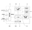
図1において、ネットワークカメラ100は、コネクタ1、コネクタ2、RJ45コネクタ3、電源切替部4、制御ブロック101、制御ブロック102を備えている。更に、制御ブロック101は、モータ駆動制御部7、照明部8、フィルタ切替部9を備えている。制御ブロック102は、撮像・画像処理部5、ネットワーク部6、CPU部10を備えている。尚、図1並びに後述の図2及び図3における三角矢印付きの線は電源供給ラインを示し、通常の矢印付きの線は制御信号ラインを示す。
In FIG. 1, the
ネットワークカメラ100は、電源切替部4により、複数の電源(ACアダプタからの電源、汎用電源、LANケーブルを用いて電源を供給する規格IEEE802.3afで規定される電源に準ずるPoE電源)から選択的に複数の電源からの電力供給を受けることができる。また、ネットワークカメラ100は、LAN等のネットワークを介して複数のクライアント装置(情報処理装置)と通信可能に構成されている。また、ネットワークカメラ100は、ネットワークカメラに供給している電源の種類に応じて動作機能や動作状態の切替を行う。そして、ネットワークカメラ100は、ネットワークカメラ100に供給している電源に関する情報をネットワークを介してクライアント装置に送信する。クライアント装置は、その表示部表示画面の画面に電源の種類に関する表示を行うことが可能に構成されている。
The
ネットワークカメラ100各部の構成を説明する。コネクタ1は、ACアダプタからの電力を電源切替部4に供給するためのインターフェースである。コネクタ2は、汎用電源(DC12V、AC24V)からの電力を電源切替部4に供給するためのインターフェースであり、スクリュー端子台等から構成される。RJ45コネクタ3は、イーサネット(登録商標)信号及びPoE電源からの電力を電源切替部4に供給するためのインターフェースである。電源切替部4は、PoE電源の受電部(図3参照)を備えている。そして、電源切替部4は、コネクタ1、コネクタ2、RJ45コネクタ3を介して受けた電力の供給を検知し、上記3つの電源から1つの電源を選択してネットワークカメラ内部に電力供給を行う。電源切替部4の詳細については図3に基づき説明する。
The configuration of each part of the
なお、本実施の形態では、PoE電源からの電力の供給は、ACアダプタ,汎用電源などの他の電力の供給より制限されているものとして説明する。すなわち、PoE電源に替えて、電力の供給がACアダプタ,汎用電源などの他の電力の供給より制限されているものであれば、本実施の形態を適用することが可能である。 In the present embodiment, the description will be made assuming that the supply of power from the PoE power supply is limited by the supply of other power such as an AC adapter and a general-purpose power supply. In other words, the present embodiment can be applied as long as power supply is limited by other power supply such as an AC adapter or a general-purpose power supply instead of the PoE power supply.
撮像・画像処理部5は、レンズ及び撮像素子から構成され所定の区域の撮影を行う撮像部と、撮影された画像に対するデジタル画像処理を行う回路を有する画像処理部とを備えている。ネットワーク部6は、RJ45コネクタ3を介してネットワークカメラ100外部との間で通信を行う。モータ駆動制御部7は、CPU部10の指令に従い、ネットワークカメラ100における各種動作(パン動作・チルト動作・ズーム動作等)を実行する複数のモータ部の駆動制御を行う。モータ部の詳細については図2に基づき説明する。
The imaging /
照明部8は、撮像・画像処理部5による撮像動作の補助として、照明を行うものであり、例えば赤外照明のLED等から構成されている。照明部8は、所定のタイミング(タイマの計時情報、外部の照度を検出するセンサ出力、クライアント装置からの指令)に応じてオン/オフされる。フィルタ切替部9は、赤外線カットフィルタの出し入れに伴う、赤外線カットフィルタの切替を行うものであり、不図示のモータ及びソレノイドにより駆動される。CPU部10は、電源切替部4、撮像・画像処理部5、ネットワーク部6、モータ駆動制御部7、照明部8、フィルタ切替部9の制御を含む、ネットワークカメラ100全般の立ち上げや制御を司る。また、CPU部10は、プログラムに基づき図4のフローチャートに示す処理を実行する。
The
図2は、ネットワークカメラ100のモータ駆動制御部7に対するモータ部の接続例を示す図である。
FIG. 2 is a diagram illustrating a connection example of the motor unit with respect to the motor
図2において、モータ駆動制御部7には、モータ部A21、モータ部B22、モータ部C23、モータ部D24、モータ部E25が接続されている。尚、本実施の形態では、モータ駆動制御部7に5台のモータ部が接続されている構成を例に挙げるが、モータ部の接続台数はネットワークカメラ100の機能に応じて増減することが可能である。
In FIG. 2, the motor
モータ部A21は、レンズのアイリスを調整する際の駆動力を発生するアイリス・モータから構成されている。モータ部B22は、レンズのフォーカス制御を行う際の駆動力を発生するフォーカス・モータから構成されている。モータ部C23は、レンズのズーム制御を行う際の駆動力を発生するズーム・モータから構成されている。モータ部D24は、ネットワークカメラ100のチルト動作(垂直方向の回転動作)を行う際の駆動力を発生するチルト・モータから構成されている。モータ部E25は、ネットワークカメラ100のパン動作(水平方向の回転動作)を行う際の駆動力を発生するパン・モータから構成されている。
The motor unit A21 is composed of an iris motor that generates a driving force for adjusting the iris of the lens. The motor unit B22 includes a focus motor that generates a driving force when performing lens focus control. The motor unit C23 includes a zoom motor that generates a driving force when performing zoom control of the lens. The motor unit D24 includes a tilt motor that generates a driving force when the
図3は、ネットワークカメラ100の電源切替部4の詳細構成を示すブロック図である。
FIG. 3 is a block diagram illustrating a detailed configuration of the power
図3において、電源切替部4は、PoE受電部31、センサ32、センサ33、センサ34、第1のスイッチ(SW1)35、制御部36、第2のスイッチ(SW2)37、DC/DCコンバータ38を備えている。
In FIG. 3, the
PoE受電部31は、RJ45コネクタ3に接続されたPoE電源の電力を供給する給電装置(Powered Device)の認証を行う。センサ32は、コネクタ1に接続されたACアダプタからの電力の供給状態を監視する。センサ33は、コネクタ2に接続された汎用電源からの電力の供給状態を監視する。センサ34は、RJ45コネクタ3に接続されたPoE電源の状態(電流値等)を監視する。第1のスイッチ(SW1)35は、ACアダプタからの電源、汎用電源、PoE電源から1つの電源を選択する切替動作を行う回路である。
The PoE
制御部36は、センサ32〜センサ34から監視情報を受け取り、PoE受電部31を制御すると共に、制御ブロック2のCPU部10と通信を行う。第2のスイッチ(SW2)37は、PoE受電部31により認証されたPoE電源のIEEE 802.3af規格に基づく電力クラスを切替える。DC/DCコンバータ38は、第1のスイッチ(SW1)35により選択された電源をネットワークカメラ100の内部電源に変換する回路である。
The
上記構成において、電源切替部4のPoE受電部31は、受電前に、PoE電源の給電装置(不図示)に対する認証を行い、PoE電源の電力クラスを決定する。PoE受電部31では、PoE電源の電力クラスを変更することが可能である。PoE受電部31におけるPoE電源の電力クラスの決定は、第2のスイッチ37により電力クラスを切替えることもできるし、CPU部10からの指令に基づき電力クラスを切替えることもできる。
In the above configuration, the PoE
次に、CPU部10は、現在、ネットワークカメラ内部に供給されている電力がPoE電源からのものであるかどうかを示す情報と、上記決定された電力クラスの情報を、電源切替部4から取得する。そして、CPU部10は、PoE電源からネットワークカメラ内部に給電が行われている場合には、モータ駆動制御部7、照明部8、フィルタ切替部9を含む制御ブロック101の動作制限を実行する。CPU部10は、動作制限処理を電力クラスに応じて変更する。また、CPU部10は、映像転送に関する撮像・画像処理部5、ネットワーク部6、CPU部10を含む制御ブロック102に対しては動作制限の影響を受けないように動作制限の対象としての優先順位を下げる。
Next, the
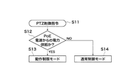
図6は、クライアント装置からRJ45コネクタ3を介してPTZ制御指令を受信したときのCPU部10の制御モードに関する動作処理を示すフローチャートである。なお、以下に説明するPTZ制御指令とは、ネットワークカメラの撮像方向(パン,チルト)およびズーム倍率のうち少なくともいずれか1つを制御するための指令を指す。
FIG. 6 is a flowchart showing an operation process related to the control mode of the
図6において、CPU部10は、ステップS11でPTZ制御指令を受信したと判断すると、ステップS12の処理に進む。ステップS12において、CPU部10は、電源切替部4からの通知を参照し、PoE電源からの電力供給を受けているか、あるいはそれ以外の電源からの電力の供給を受けているか判断する。
In FIG. 6, when the
PoE電源からの電力供給を受けていると判断した場合、CPU10は、ステップS13の処理に進み、図4に示す動作制限モードに対応する処理を実行する。一方、PoE電源以外の電源からの電力の供給を受けていると判断した場合、CPU部10は、ステップS14の処理に進み、通常の制御モードに対応する処理を実行する。なお、通常の制御モードとは、PTZ制御指令に対応するモータ部A〜Eの駆動を複数並行して駆動させる制御モードである。
If it is determined that the power supply from the PoE power supply is received, the
次に、本実施の形態のネットワークカメラの動作制限モードにおけるCPU部10の処理について図1乃至図4を参照しながら詳細に説明する。
Next, the processing of the
CPU部10は、ネットワークカメラ内部にPoE電源から電力が供給されていると判断した場合(図6のステップS12でYES)、CPU部10が制御ブロック101の構成要素の動作制限を行う。
When the
図4は、CPU部10がモータ駆動制御部7に対して駆動制御の制限を実行させる動作処理(モータ駆動制御処理)のフローチャートである。
FIG. 4 is a flowchart of an operation process (motor drive control process) in which the
以下の説明では、モータ部A21(アイリス・モータ)、モータ部B22(フォーカス・モータ)は、被写体によって自動的に動作するAF制御の場合について述べる。 In the following description, the case of AF control in which the motor unit A21 (iris motor) and the motor unit B22 (focus motor) automatically operate depending on the subject will be described.
図4において、ネットワークカメラ100のCPU部10は、クライアント装置からネットワークカメラ100に対するパン・チルト・ズーム(以下PTZ)の動作指令を受信すると(ステップS1)、モータ部A21(アイリス・モータ)、モータ部B22(フォーカス・モータ)の動作を停止する(ステップS2)。次に、CPU部10は、モータ部E25(パン・モータ)によるパン動作を開始する(ステップS3)。その後、CPU部10は、モータ部E25(パン・モータ)によるパン動作が完了したかどうかを判定し(ステップS4)、パン動作が完了したと判断した場合はステップS5に進む。
In FIG. 4, when the
次に、CPU部10は、モータ部D24(チルト・モータ)によるチルト動作を開始する(ステップS5)。その後、CPU部10は、モータ部D24(チルト・モータ)によるチルト動作が完了したかどうかを判定し(ステップS6)、チルト動作が完了したと判断した場合はステップS7に進む。
Next, the
次に、CPU部10は、モータ部C23(ズーム・モータ)によるズーム動作を開始する(ステップS7)。その後、CPU部10は、モータ部C23(ズーム・モータ)によるズーム動作が完了したかどうかを判定し(ステップS8)、ズーム動作が完了したと判断した場合はステップS9に進む。次に、CPU部10は、停止中のモータ部A21(アイリス・モータ)、モータ部B22(フォーカス・モータ)の動作を再開し(ステップS9)、本処理を終了する(ステップS10)。
Next, the
上述した図4のモータ駆動制御処理は、ネットワークカメラ100においてアイリス・モータ、フォーカス・モータの動作を一時停止させると共に、PTZ動作(3つの動作)のうち2つ以上の動作が同時に起こらないように制御する処理を行っている。この処理によって、電力の消費を制限し、適切な動作を実現している。
The above-described motor drive control process of FIG. 4 temporarily stops the operations of the iris motor and the focus motor in the
尚、本実施の形態では、モータ部A21(アイリス・モータ)、モータ部B22(フォーカス・モータ)の動作を停止してからPTZ動作(ステップS3〜ステップS8)を行っているが、これに限定されるものではない。PoE電源の電力クラスが0或いは3でその許容電力を超えなければ、モータ部A21(アイリス・モータ)、モータ部B22(フォーカス・モータ)の片方或いは両方を動作させたままにしてもよい。 In this embodiment, the PTZ operation (steps S3 to S8) is performed after the operations of the motor unit A21 (iris motor) and the motor unit B22 (focus motor) are stopped. Is not to be done. If the power class of the PoE power supply is 0 or 3 and does not exceed the allowable power, one or both of the motor unit A21 (iris motor) and the motor unit B22 (focus motor) may be left operating.
また、PTZ動作(ステップS3〜ステップS8)を、パン、チルト、ズームの順番で行っているが、これに限定されるものではない。PTZ動作の順番は入れ替えてもよい。 Further, the PTZ operation (steps S3 to S8) is performed in the order of pan, tilt, and zoom, but is not limited to this. The order of the PTZ operations may be changed.
また、PTZ動作では、モータ部C23(ズーム・モータ)、モータ部D24(チルト・モータ)、モータ部E25(パン・モータ)のうち任意の2つのモータ部を動作させ、どちからのモータ部の動作が完了した時点で残りのモータ部を動作させるようにしてもよい。2つのモータ部を動作させる場合、動作完了に一番時間のかかるモータ部を最初に動作させるモータ部の1つにする。これにより、PTZ動作終了までの時間を短縮することができる。 In the PTZ operation, any two motor units among the motor unit C23 (zoom motor), the motor unit D24 (tilt motor), and the motor unit E25 (pan motor) are operated, and either of the motor units is operated. The remaining motor units may be operated when the operation is completed. When two motor units are operated, the motor unit that takes the longest time to complete the operation is set as one of the motor units to be operated first. Thereby, the time until the end of the PTZ operation can be shortened.
また、PoE電源の電力クラスが2または1で更に許容電力が低い場合には、図4のフローチャートのモータ駆動制御処理に加え、モータ部の駆動電力を下げる制御を同時に行うことで、PoE電源の許容電力を超えないように制御してもよい。 Further, when the power class of the PoE power source is 2 or 1, and the allowable power is further lower, in addition to the motor drive control process of the flowchart of FIG. You may control so that allowable power may not be exceeded.
次に、上記と同様に、ネットワークカメラ内部に供給されている電源がPoE電源であると判断した場合に、制御ブロック101の構成要素の動作制限を行う際の照明部8、フィルタ切替部9の動作と関連付けたモータ駆動制御の例について説明する。
Next, similarly to the above, when it is determined that the power supplied to the inside of the network camera is a PoE power supply, the
フィルタ切替部9は、不図示のモータ及びソレノイドにより駆動され一時的に電力を消費する。そのため、本実施の形態では、クライアント装置からネットワークカメラ100に対しフィルタ切替部9の動作指令が送信されてきた場合には、フィルタ切替部9の動作が終了するまでモータ駆動制御部7の制御による上記PTZ動作を行わないようにする。或いは、モータ駆動制御部7の制御によるPTZ動作中であれば、PTZ動作が終了してからフィルタ切替部9の動作を行うようにする。
The
一方、照明部8のオン/オフは、クライアント装置側からの指令に基づき行う場合、タイマによる計時が所定時間(時刻)に達したときに行う場合、ネットワークカメラ外部の照度の検出結果に基づき行う場合などがある。照明部8のオン(作動)によりネットワークカメラ100での消費電力は定常的に増えるので、照明部8のオン/オフに応じてモータ駆動制御部7の制御によるPTZ動作を変更するようにする。PTZ動作の変更例としては以下のようなものが考えられる。
On the other hand, when the
例えば、PTZ動作時において照明部8がオフの時は、モータ部A21(アイリス・モータ)、モータ部B22(フォーカス・モータ)の停止を行わないようにする。一方、PTZ動作時において照明部8がオンとなった時は、モータ部A21(アイリス・モータ)、モータ部B22(フォーカス・モータ)の停止を行うようにする。
For example, when the
また、照明部8がオフの時は、PTZ動作を2つのモータ部を同時に動作させることで行うようにする。一方、照明部8がオンの時は、PTZ動作を、図4のステップS3〜ステップS8に示したように1つのモータ部をその都度動作/停止させることで順番に行うようにする。
When the
また、照明部8の消費電力が大きい構成の場合で、ネットワークカメラ100のI/O出力部(不図示)に外部照明装置(不図示)が接続されている構成の場合には、以下のような制御を行う。即ち、照明部8をオンとする指令に対し照明部8のオンは行わず、上記I/O出力部から外部照明装置に対し外部照明装置をオンとする指令信号を出力するようにする。
In the case of a configuration in which the power consumption of the
次に、ネットワークカメラ内部に供給されている電源がPoE電源である場合で制御ブロック101の構成要素の動作制限を行う際に、モータ駆動制御部7によるモータ駆動制御のその他の例について説明する。
Next, another example of motor drive control by the motor
モータ駆動制御部7は、モータ部A21、モータ部B22、モータ部C23、モータ部D24、モータ部E25の消費電力を削減するため、駆動電圧や駆動電流を下げるように制御する。この場合、駆動電圧や駆動電流を下げると、モータのトルクが下がってしまう。そこで、モータ駆動制御部7は、モータ部の駆動力を該当機構に伝達するギアのギア比を下げ、モータ部の動作速度が低下してもPTZ動作に必要なトルクが確保できるように制御する。
The motor
また、電源切替部4からカメラ内部へ供給されるPoE電源の電流値を電源切替部4内部のセンサ34により検出し、CPU部10が、PoE電源の許容電力を超えないぎりぎりの電力になるようにモータ駆動制御部7における制御値を切替えるようにしてもよい。
Further, the current value of the PoE power source supplied from the power
また、上記モータ駆動制御は、モータ部A21、モータ部B22、モータ部C23、モータ部D24、モータ部E25の全てについて行わなくてもよい。電力消費の多いモータ部や動作速度に対する優先度の低いモータ部に対してPoE電源の電力クラスに応じて行うようにしてもよい。 The motor drive control may not be performed for all of the motor unit A21, the motor unit B22, the motor unit C23, the motor unit D24, and the motor unit E25. You may make it carry out according to the electric power class of PoE power supply with respect to the motor part with much power consumption, or the motor part with low priority with respect to operation speed.
上記例では、3つのモータ部(モータ部C23、モータ部D24、モータ部E25)を動作させることでネットワークカメラ100にPTZ動作を行わせる場合を説明したが、これに限定されるものではない。3つのモータ部のうち何れか1つのモータ部或いは何れか2つのモータ部を動作させる場合にも適用することができる。
In the above example, the case where the
また、PoE電源の電力クラス0または3の場合にはPoE電源の許容電力を満たすが、電力クラス1または2ではPoE電源の許容電力を満たさない場合には、次のようにしてもよい。即ち、PoE電源の電力クラス1または2の場合に上記の手法でPoE電源の許容電力の範囲内になるように制御を行うようにしてもよい。
In addition, the PoE
また、ネットワークカメラ100がPoE電源からの電力供給により動作を行っている場合、ネットワークカメラ100に対しその動作指令を行うことができるクライアント装置の数を、他の電源からの電力供給による動作時よりも減らすようにしてもよい。
Further, when the
次に、クライアント装置側におけるビューワを利用したネットワークカメラ100の供給電源に関する情報の表示及びネットワークカメラ100に対する動作指令等について図5を参照しながら説明する。
Next, display of information related to the power supply of the
図7は、クライアント装置70の概略構成を示すブロック図である。
FIG. 7 is a block diagram illustrating a schematic configuration of the
図7において、CPU部71は、クライアント装置70全体を統括制御する処理ユニットである。また、2次記憶装置72は、ハードディスクドライブなどからなる記憶装置であり、クライアント装置70の処理をCPU部71に実行させるためのプログラムを記憶する。また、RAM73は、プログラムを2次記憶装置72から読み出し、CPU部71に実行させるために一時記憶するためのメモリである。
In FIG. 7, a
また、インターフェース(I/F)74は、ネットワークを介してネットワークカメラ100に制御指令を送信したり、ネットワークカメラ100から送信された映像データなどのデータを受信したりするためのインターフェースである。表示制御部75は、CPU部71からの指示に応じて受信した映像データを表示装置76の表示画面に表示させたり、図5に示すGUI(Graphical User Interface)を表示させたりする回路である。また、表示装置76は、液晶表示装置などによって構成される。
The interface (I / F) 74 is an interface for transmitting a control command to the
図5は、クライアント装置70の表示装置76上の表示画面を示す図である。
FIG. 5 is a diagram showing a display screen on the
図5において、クライアント装置の表示画面50には、映像表示領域51、電源種類表示領域52、ボタン表示部53、ツールバー54、55、56が配設されている。
In FIG. 5, the
映像表示領域51は、クライアント装置70にネットワークを介して転送されたネットワークカメラ100からの映像を表示する領域である。電源種類表示領域52は、ネットワークカメラ100に電力供給している電源の種類(図示例ではPoE電源)を表示する。ボタン表示領域53は、カメラ制御権(ネットワークカメラ100の動作を指令する権利)を取得するためのボタンを表示する領域である。
The
ツールバー54は、ネットワークカメラ100のパンの操作を行うためのものである。ツールバー55は、ネットワークカメラ100のチルトの操作を行うためのものである。ツールバー56は、ネットワークカメラ100のズームの操作を行うためのものである。ツールバー54,55,56のいずれにおいてもカーソル58をそのつまみの位置に合わせ、移動させることによって操作指令を生成することができる。ツールバー54,55,56は、互いに独立しているため、ネットワークカメラ100が図6のステップS13の動作制限モードである場合に適している。
The
矩形枠57は、カーソル58をその矩形枠57の頂角に合わせることによって拡大・縮小が可能である。また、カーソル58を用いたドラッグアンドドロップ操作によって矩形枠57の移動操作が可能である。CPU部71は、矩形枠57の拡大・縮小、移動に従って、ネットワークカメラ100に対する制御指令を生成する。矩形枠57を用いたネットワークカメラ100の操作は、一度にPTZ(パン,チルト,ズーム)制御指令を生成する場合がある。そのため、矩形枠57を用いたネットワークカメラ100の操作は、動作制限がなされていない通常の制御モードの場合に適しているが、モータを並行して動作させる必要のある動作制限モードには適していない。
The
ネットワークカメラ100では、電源切替部4によりネットワークカメラ内部に供給されている電源がPoE電源であることを検出する。これに伴い、CPU部10は、ネットワークカメラへの供給電源がPoE電源であることを示す電源情報を、ネットワーク部6及びイーサネット(登録商標)を介してクライアント装置70に通知する。クライアント装置70のCPU部71は、ネットワークカメラ100からの通知に伴い、表示画面50の電源種類表示領域52の表示を変化させる。これにより、操作者は、ネットワークカメラ100がPoE電源から電力供給され、ネットワークカメラ100の動作が制限されている状態であることを視覚的に把握することができる。更に、電源種類表示領域52には、PoE電源の現在の電力クラスも解るように色や数字を変えるなどの表示を行ってもよい。
In the
また、ネットワークカメラ100では、3種類の電源入力部(コネクタ1〜3)があるので、電源切替部4によりネットワークカメラ100が現在どの電源により動作しているかを検出する。この検出に基づいて、CPU部10は、ネットワークカメラ100が現在どの電源により動作を行っているかを示す電源情報を、ネットワーク部6及びイーサネット(登録商標)を介してクライアント装置70に通知する。クライアント装置70のCPU部71は、ネットワークカメラ100からの通知に従って、表示装置76の表示画面50の電源種類表示領域52に、ネットワークカメラ100が現在どの電源により動作を行っているかを操作者に解るように表示させる。
In the
なお、CPU部71は、電源種類表示領域52に、ネットワークカメラ100にPTZ操作を実行可能なカメラ制御権を取得した場合に、ネットワークカメラ100の使用電源(PoE電源、その他の電源)の種類を表示するようにしてもよい。
In addition, when the
[第2の実施の形態]
本発明の第2の実施の形態は、クライアント装置70側でパン,チルト,ズームの制御指令を同時に生成することを制限することによって、ネットワークカメラ100の動作制限モードに対応させるための実施形態である。なお、以下に説明する処理以外は第1の実施の形態と同様である。
[Second Embodiment]
The second embodiment of the present invention is an embodiment for supporting the operation restriction mode of the
図8は、ネットワークカメラ100のカメラ制御権を取得したときのクライアント装置70のCPU部71が実行する表示制御処理フローチャートである。
FIG. 8 is a flowchart of a display control process executed by the
図8において、ステップS81において、CPU部71は、ネットワークカメラ100から現在電力をネットワークカメラ100に対して供給している電源の種類に関する情報の受信を待ち、受信した場合、ステップS82の処理へ進む。
In FIG. 8, in step S81, the
ステップS82において、CPU部71は、受信した情報に基づいて、現在電力をネットワークカメラ100に対して供給している電源がPoE電源であるか否か判断する。PoE電源であると判断した場合、ステップS83の処理に進む。また、PoE電源以外の電源であると判断した場合、ステップS84の処理に進む。
In step S82, based on the received information, the
ステップS83において、CPU部71は、ネットワークカメラ100が動作制限モードであると判断し、矩形枠57の表示を非表示に制御する。
In step S83, the
一方、ステップS84において、CPU部71は、ネットワークカメラ100が通常の制御モードであると判断し、領域51上に矩形枠57を表示させる。以上のような処理を実行させることによって、動作制限モードであっても違和感のない操作をユーザに対して提供することが可能となる。
On the other hand, in step S <b> 84, the
以上説明したように、本実施の形態によれば、ネットワークカメラがPoE電源からの電力供給のみで動作を行っている場合には、ネットワークカメラが有する複数の機能のうち一部の機能について動作制限を行う。これにより、PoE電源の許容量を超えることがなくなるため、PoE電源の給電側から過負荷によってネットワークカメラに対する電力供給が遮断されることがなくなり、ネットワークカメラの安定動作が可能となる。 As described above, according to the present embodiment, when the network camera is operating only by supplying power from the PoE power supply, operation restrictions are imposed on some of the functions of the network camera. I do. As a result, the allowable amount of the PoE power supply is not exceeded, so that the power supply to the network camera is not interrupted by the overload from the power supply side of the PoE power supply, and the network camera can be stably operated.
また、クライアント装置側では、クライアント装置に接続したネットワークカメラで選択した電源により電力供給を受けていることを示す電源情報をネットワークカメラから受信し、表示画面に表示する。これに伴い、ネットワークカメラの電源がどこから供給されているかを表示画面で確認することができる。これにより、ネットワークカメラに対するPoE電源からの電力供給時にネットワークカメラの一部の機能に動作制限を行っても、それは動作不良ではないことをクライアント装置側で把握することが可能となる。 On the client device side, power supply information indicating that power is supplied from the power supply selected by the network camera connected to the client device is received from the network camera and displayed on the display screen. Along with this, it is possible to confirm on the display screen where the power of the network camera is supplied from. As a result, it is possible for the client device side to grasp that even if operation restriction is performed on some functions of the network camera when power is supplied from the PoE power source to the network camera, it is not an operation failure.
また、クライアント装置側は、ネットワークカメラがPoE電源からの電力供給のみで動作を行っている旨をネットワークカメラから受信した場合、ネットワークカメラの一部の機能に対し動作制限を行う指令をネットワークカメラに送信する。これにより、ネットワークカメラの制御負荷を軽減することが可能となり、ネットワークカメラの小型化や省電力化を図ることが可能となる。 In addition, when the client device receives from the network camera that the network camera is operating only by supplying power from the PoE power supply, the client device side instructs the network camera to restrict the operation of some functions of the network camera. Send. As a result, the control load of the network camera can be reduced, and the network camera can be reduced in size and power can be saved.
[他の実施の形態]
上記実施の形態では、ネットワークカメラの利用形態については特に言及しなかったが、所定区域の撮影に基づく監視、商店内に陳列している商品を撮影しモニタに表示する商品案内、観光地の風景等を撮影しモニタに表示する観光案内など各種分野に適用可能である。
[Other embodiments]
In the above embodiment, the use form of the network camera is not particularly mentioned, but monitoring based on photographing of a predetermined area, product guidance for photographing products displayed in the store and displaying them on the monitor, scenery of a sightseeing spot The present invention can be applied to various fields such as sightseeing guides that shoot and display them on a monitor.
また、本発明の目的は、前述した各実施の形態の機能を実現するソフトウェアのプログラムコードを記憶した記憶媒体を、システム或いは装置に供給し、そのシステム或いは装置のコンピュータ(またはCPUやMPU等)が記憶媒体に格納されたプログラムコードを読み出し実行することによっても達成される。 Another object of the present invention is to supply a storage medium storing software program codes for realizing the functions of the above-described embodiments to a system or apparatus, and the computer of the system or apparatus (or CPU, MPU, or the like). Is also achieved by reading and executing the program code stored in the storage medium.
この場合、記憶媒体から読み出されたプログラムコード自体が前述した各実施の形態の機能を実現することになり、そのプログラムコード及び該プログラムコードを記憶した記憶媒体は本発明を構成することになる。 In this case, the program code itself read from the storage medium realizes the functions of the above-described embodiments, and the program code and the storage medium storing the program code constitute the present invention. .
また、プログラムコードを供給するための記憶媒体としては、例えば、ハードディスク、光磁気ディスク、CD−ROM、CD−R、CD−RW、DVD−ROM、DVD−RAM、DVD−RW、DVD+RW等の光ディスク、磁気テープ、不揮発性のメモリカード、ROM等を用いることができる。または、プログラムコードをネットワークを介してダウンロードしてもよい。 Examples of the storage medium for supplying the program code include optical disks such as a hard disk, a magneto-optical disk, a CD-ROM, a CD-R, a CD-RW, a DVD-ROM, a DVD-RAM, a DVD-RW, and a DVD + RW. Magnetic tape, nonvolatile memory card, ROM, etc. can be used. Alternatively, the program code may be downloaded via a network.
また、コンピュータが読み出したプログラムコードを実行することにより、前述した各実施の形態の機能が実現されるだけではなく、そのプログラムコードの指示に基づき、コンピュータ上で稼動しているOS(オペレーティングシステム)等が実際の処理の一部または全部を行い、その処理によって前述した各実施の形態の機能が実現される場合も含まれる。 Further, by executing the program code read by the computer, not only the functions of the above-described embodiments are realized, but also an OS (Operating System) running on the computer based on the instruction of the program code Includes a case where the functions of the above-described embodiments are realized by performing part or all of the actual processing.
更に、記憶媒体から読み出されたプログラムコードが、コンピュータに挿入された機能拡張ボードやコンピュータに接続された機能拡張ユニットに備わるメモリに書き込まれた後、次のプログラムコードの指示に基づき、その拡張機能を拡張ボードや拡張ユニットに備わるCPU等が実際の処理の一部または全部を行い、その処理によって前述した各実施の形態の機能が実現される場合も含まれる。 Furthermore, after the program code read from the storage medium is written to the memory provided in the function expansion board inserted into the computer or the function expansion unit connected to the computer, the program code is expanded based on the instruction of the next program code. This includes the case where the CPU or the like provided in the expansion board or expansion unit performs some or all of the actual processing and the functions of the above-described embodiments are realized by the processing.
4 電源切替部(電源切替手段)
5 撮像・画像処理部
6 ネットワーク部
7 モータ駆動制御部
8 照明部(照明手段)
9 フィルタ切替部
10 CPU部(制御手段)
21 モータ部A(アイリス・モータ)(駆動手段)
22 モータ部B(フォーカス・モータ)(駆動手段)
23 モータ部C(ズーム・モータ)(駆動手段)
24 モータ部D(チルト・モータ)(駆動手段)
25 モータ部E(パン・モータ)(駆動手段)
31 PoE受電部(受電手段)
50 表示画面
51 画像表示部
52 電源種類表示領域
53 ボタン表示部
100 ネットワークカメラ(撮像装置)
4 Power supply switching part (Power supply switching means)
5 Imaging /
9 Filter switching
21 Motor part A (iris motor) (drive means)
22 Motor part B (focus motor) (drive means)
23 Motor part C (zoom motor) (drive means)
24 Motor part D (tilt motor) (drive means)
25 Motor part E (pan motor) (drive means)
31 PoE power receiving unit (power receiving means)
50
Claims (5)
前記第1の外部電源は、IEEE802.3afに基づいてLANを介して供給される電源であり、
撮像を行う撮像手段と、
前記撮像手段における撮像範囲を変更するための複数の駆動手段と、
外部装置から前記撮像範囲を変更するための制御指令を受信する受信手段と、
前記第1の外部電源を認証して当該第1の外部電源に係る電力クラスを決定する電力クラス決定手段と、
前記第1の外部電源から電力が供給されている場合には、前記電力クラスに応じて決定される同時に駆動する駆動手段の数を、前記第2の外部電源から電力が供給される場合よりも少ない第1の数に制限し、前記受信手段によって前記制御指令を受信した際、前記制御指令に応じて駆動すべき駆動手段の数が前記第1の数よりも多いと、前記駆動手段を順次駆動させる制御手段とを備えることを特徴とする撮像装置。 An imaging apparatus in which power is selectively supplied from a plurality of external power sources including a first external power source and a second external power source,
The first external power source is a power source supplied via a LAN based on IEEE 802.3af.
Imaging means for imaging;
A plurality of driving means for changing an imaging range in the imaging means;
Receiving means for receiving a control command for changing the imaging range from an external device;
Power class determining means for authenticating the first external power source and determining a power class related to the first external power source;
When power is supplied from the first external power source, the number of driving means that are driven simultaneously determined in accordance with the power class is set to be greater than that when power is supplied from the second external power source. When the number of driving means to be driven in response to the control command is larger than the first number when the control command is received by the receiving unit, the driving unit is sequentially switched. An imaging apparatus comprising: a control means for driving.
前記第1の外部電源から電力が供給されている場合に、前記受信手段で前記制御指令を受信すると、前記制御手段は、前記第1〜前記第3の駆動手段のうちの2つを同時に駆動し、当該駆動された2つの駆動手段の1つの完了後であって当該駆動手段の他方の駆動の完了前に残りの駆動手段の駆動を開始することを特徴とする請求項1に記載の撮像装置。 As the plurality of driving means, a first driving means driven when performing a zoom operation of the imaging means, a second driving means driven when performing a tilting operation of the imaging means, and an imaging means There is a third driving means that is driven when performing the pan operation,
When power is supplied from the first external power source and the receiving means receives the control command, the control means drives two of the first to third driving means simultaneously. 2. The imaging according to claim 1, wherein driving of the remaining driving means is started after completion of one of the two driven driving means and before completion of the other driving of the driving means. apparatus.
前記第1の外部電源から電力が供給されている場合に、前記受信手段が前記制御指令を受信すると、前記制御手段は前記アイリス駆動手段および前記フォーカス駆動手段の動作を停止した後、前記撮像範囲を変更するための複数の駆動手段を駆動させることを特徴とする請求項1に記載の撮像装置。 And an iris driving means that is driven when adjusting the iris of the imaging means, and a focus driving means that is driven when performing focus control of the imaging means,
When power is supplied from the first external power source and the receiving unit receives the control command, the control unit stops the operations of the iris driving unit and the focus driving unit, and then the imaging range. The image pickup apparatus according to claim 1, wherein a plurality of driving means for changing the position is driven.
前記第1の外部電源は、IEEE802.3afに基づいてLANを介して供給される電源であり、
前記制御手段が、前記第1の外部電源を認証して当該第1の外部電源に係る電力クラスを決定する電力クラス決定ステップと、
前記第1の外部電源から電力が供給されている場合には、前記電力クラスに応じて決定される同時に駆動可能な前記駆動手段の数を、前記第2の外部電源から電力が供給される場合よりも少ない第1の数に制限する第1の制御ステップと、
前記受信手段によって前記制御指令を受信した際、前記制御指令に応じて駆動すべき駆動手段の数が前記第1の数よりも多いと、前記駆動手段を順次駆動させる第2の制御ステップとを実行することを特徴とする撮像装置の制御方法。 Imaging means for performing imaging, a plurality of driving means for changing the imaging range in the imaging means, a receiving means for receiving a control command for changing the imaging range from an external device, and driving of the driving means A control method for controlling an imaging apparatus that is selectively supplied with power from a plurality of external power sources including a first external power source and a second external power source.
The first external power source is a power source supplied via a LAN based on IEEE 802.3af.
The control means authenticates the first external power source and determines a power class related to the first external power source; and
When power is supplied from the first external power supply, the number of the drive means that can be driven simultaneously determined according to the power class is determined based on the power supplied from the second external power supply. A first control step that limits the first number to less than,
A second control step of sequentially driving the drive means when the number of drive means to be driven in response to the control command is greater than the first number when the control instruction is received by the receiving means; An image pickup apparatus control method comprising: executing the image pickup apparatus;
前記第1の外部電源は、IEEE802.3afに基づいてLANを介して供給される電源であり、
前記撮像装置が備えるコンピュータに、
前記第1の外部電源を認証して当該第1の外部電源に係る電力クラスを決定する電力クラス決定手順と、
前記第1の外部電源から電力が供給されている場合には、前記電力クラスに応じて決定される同時に駆動可能な前記駆動手段の数を、前記第2の外部電源から電力が供給される場合よりも少ない第1の数に制限する第1の制御手順と、
前記受信手段によって前記制御指令を受信した際、前記制御指令に応じて駆動すべき駆動手段の数が前記第1の数よりも多いと、前記駆動手段を順次駆動させる第2の制御手順とを実行させることを特徴とするプログラム。 An imaging unit that performs imaging, a plurality of driving units for changing an imaging range in the imaging unit, and a receiving unit that receives a control command for changing the imaging range from an external device, A program for controlling an imaging device to which power is selectively supplied from a plurality of external power sources including a power source and a second external power source,
The first external power source is a power source supplied via a LAN based on IEEE 802.3af.
In the computer provided in the imaging device,
A power class determination procedure for authenticating the first external power source and determining a power class related to the first external power source;
When power is supplied from the first external power supply, the number of the drive means that can be driven simultaneously determined according to the power class is determined based on the power supplied from the second external power supply. A first control procedure that limits to a first number less than,
A second control procedure for sequentially driving the drive means when the number of drive means to be driven in response to the control command is greater than the first number when the control instruction is received by the receiving means; A program characterized by being executed.
Priority Applications (1)
| Application Number | Priority Date | Filing Date | Title |
|---|---|---|---|
| JP2006132613A JP4944490B2 (en) | 2006-05-11 | 2006-05-11 | Imaging apparatus, control method, and program |
Applications Claiming Priority (1)
| Application Number | Priority Date | Filing Date | Title |
|---|---|---|---|
| JP2006132613A JP4944490B2 (en) | 2006-05-11 | 2006-05-11 | Imaging apparatus, control method, and program |
Publications (3)
| Publication Number | Publication Date |
|---|---|
| JP2007306308A JP2007306308A (en) | 2007-11-22 |
| JP2007306308A5 JP2007306308A5 (en) | 2009-07-02 |
| JP4944490B2 true JP4944490B2 (en) | 2012-05-30 |
Family
ID=38839872
Family Applications (1)
| Application Number | Title | Priority Date | Filing Date |
|---|---|---|---|
| JP2006132613A Expired - Fee Related JP4944490B2 (en) | 2006-05-11 | 2006-05-11 | Imaging apparatus, control method, and program |
Country Status (1)
| Country | Link |
|---|---|
| JP (1) | JP4944490B2 (en) |
Families Citing this family (10)
| Publication number | Priority date | Publication date | Assignee | Title |
|---|---|---|---|---|
| EP2184963B1 (en) | 2008-11-06 | 2011-10-05 | Axis AB | Housing for electronic device. |
| JP5645566B2 (en) * | 2010-09-17 | 2014-12-24 | キヤノン株式会社 | Imaging apparatus, control method therefor, and program |
| JP5697401B2 (en) * | 2010-10-28 | 2015-04-08 | キヤノン株式会社 | Power circuit |
| ITMI20121590A1 (en) * | 2012-09-24 | 2014-03-25 | Videotec Spa | SYSTEM AND METHOD OF FEEDING FOR SURVEILLANCE CAMERAS AND PROTECTIVE HOUSES FOR SUCH CAMERAS |
| JP2014222373A (en) * | 2013-05-13 | 2014-11-27 | Necプラットフォームズ株式会社 | Communication relay device and its power supply method |
| JP6347663B2 (en) * | 2014-05-12 | 2018-06-27 | キヤノン株式会社 | Control device, imaging system, control method, and program |
| JP6701043B2 (en) * | 2016-09-23 | 2020-05-27 | キヤノン株式会社 | Control device, control method and program |
| JP6836305B2 (en) | 2017-01-13 | 2021-02-24 | キヤノン株式会社 | Imaging control device and its control method |
| WO2022097505A1 (en) * | 2020-11-05 | 2022-05-12 | ソニーグループ株式会社 | Lens barrel, control method, and imaging device |
| US12449629B2 (en) | 2020-11-05 | 2025-10-21 | Sony Group Corporation | Lens barrel, control method, and imaging device |
Family Cites Families (4)
| Publication number | Priority date | Publication date | Assignee | Title |
|---|---|---|---|---|
| JPH10234021A (en) * | 1997-02-19 | 1998-09-02 | Canon Inc | Information transmission system and signal processing board |
| JP3814367B2 (en) * | 1997-03-18 | 2006-08-30 | キヤノン株式会社 | Image input device |
| JPH11122595A (en) * | 1997-10-20 | 1999-04-30 | Canon Inc | Information processing apparatus and system and method, and storage medium |
| JP2000184264A (en) * | 1998-12-14 | 2000-06-30 | Olympus Optical Co Ltd | Camera |
-
2006
- 2006-05-11 JP JP2006132613A patent/JP4944490B2/en not_active Expired - Fee Related
Also Published As
| Publication number | Publication date |
|---|---|
| JP2007306308A (en) | 2007-11-22 |
Similar Documents
| Publication | Publication Date | Title |
|---|---|---|
| US6753921B1 (en) | Camera and camera system | |
| US8345143B2 (en) | Image capturing apparatus and image capturing apparatus control method | |
| US8412959B2 (en) | Terminal apparatus, terminal apparatus controlling method, and control program | |
| EP1881395A2 (en) | Imaging apparatus and imaging system | |
| JP4944490B2 (en) | Imaging apparatus, control method, and program | |
| US9002276B2 (en) | Image providing apparatus, image output apparatus, and image output system | |
| US20080074501A1 (en) | Imaging device and control method therefor, and program for the same | |
| CN103581540A (en) | Image pickup apparatus, interchangeable lens, and camera system | |
| JP2008160792A (en) | Electronic camera and control method thereof | |
| US8269874B2 (en) | Image display system, image input apparatus and controlling method | |
| US7657568B2 (en) | Image pickup apparatus and control method therefor | |
| JP4759372B2 (en) | Communication terminal for informing wireless communication state and control method thereof | |
| JP7751479B2 (en) | Imaging device, control method, and program | |
| US8077206B2 (en) | Image pickup apparatus, communication control method, and program | |
| JP4027634B2 (en) | Electronic camera | |
| JP5159474B2 (en) | COMMUNICATION DEVICE, ITS CONTROL METHOD, PROGRAM | |
| JP2005223766A (en) | Imaging apparatus and control method thereof | |
| US12292775B2 (en) | Electronic apparatus, method of controlling the same and non-transitory computer-readable storage medium | |
| JP4265248B2 (en) | Electronic device, power control method for electronic device, power control program for electronic device | |
| US20240323523A1 (en) | Control device capable of communicating with external device, control method, and non-transitory computer-readable storage medium | |
| JP2025149062A (en) | Power supply device, optical device having optical member, and imaging system | |
| CN110650286A (en) | Output apparatus, control method thereof, and storage medium | |
| JP4194253B2 (en) | Digital camera | |
| JP2005094118A (en) | Image recording device for monitoring | |
| JP4298536B2 (en) | Image processing apparatus and computer program |
Legal Events
| Date | Code | Title | Description |
|---|---|---|---|
| A521 | Request for written amendment filed |
Free format text: JAPANESE INTERMEDIATE CODE: A523 Effective date: 20090508 |
|
| A621 | Written request for application examination |
Free format text: JAPANESE INTERMEDIATE CODE: A621 Effective date: 20090508 |
|
| A977 | Report on retrieval |
Free format text: JAPANESE INTERMEDIATE CODE: A971007 Effective date: 20101108 |
|
| A131 | Notification of reasons for refusal |
Free format text: JAPANESE INTERMEDIATE CODE: A131 Effective date: 20101207 |
|
| A521 | Request for written amendment filed |
Free format text: JAPANESE INTERMEDIATE CODE: A523 Effective date: 20110203 |
|
| A131 | Notification of reasons for refusal |
Free format text: JAPANESE INTERMEDIATE CODE: A131 Effective date: 20110705 |
|
| A521 | Request for written amendment filed |
Free format text: JAPANESE INTERMEDIATE CODE: A523 Effective date: 20110905 |
|
| TRDD | Decision of grant or rejection written | ||
| A01 | Written decision to grant a patent or to grant a registration (utility model) |
Free format text: JAPANESE INTERMEDIATE CODE: A01 Effective date: 20120227 |
|
| A01 | Written decision to grant a patent or to grant a registration (utility model) |
Free format text: JAPANESE INTERMEDIATE CODE: A01 |
|
| A61 | First payment of annual fees (during grant procedure) |
Free format text: JAPANESE INTERMEDIATE CODE: A61 Effective date: 20120302 |
|
| R151 | Written notification of patent or utility model registration |
Ref document number: 4944490 Country of ref document: JP Free format text: JAPANESE INTERMEDIATE CODE: R151 |
|
| FPAY | Renewal fee payment (event date is renewal date of database) |
Free format text: PAYMENT UNTIL: 20150309 Year of fee payment: 3 |
|
| LAPS | Cancellation because of no payment of annual fees |