JP6006024B2 - Imaging apparatus, imaging method, and program - Google Patents
Imaging apparatus, imaging method, and program Download PDFInfo
- Publication number
- JP6006024B2 JP6006024B2 JP2012148437A JP2012148437A JP6006024B2 JP 6006024 B2 JP6006024 B2 JP 6006024B2 JP 2012148437 A JP2012148437 A JP 2012148437A JP 2012148437 A JP2012148437 A JP 2012148437A JP 6006024 B2 JP6006024 B2 JP 6006024B2
- Authority
- JP
- Japan
- Prior art keywords
- unit
- zoom
- display
- imaging
- image
- Prior art date
- Legal status (The legal status is an assumption and is not a legal conclusion. Google has not performed a legal analysis and makes no representation as to the accuracy of the status listed.)
- Expired - Fee Related
Links
Images


Description
本発明は、被写体を撮像して該被写体の画像データを生成する撮像装置、撮像方法およびプログラムに関する。 The present invention relates to an imaging apparatus, an imaging method, and a program for imaging a subject and generating image data of the subject.
近年、デジタルカメラ等の撮像装置において、画像を表示する表示部の表示画面上にタッチパネルを設け、ユーザが撮影に関する操作をタッチパネルで行う技術が知られている(特許文献1参照)。この技術では、表示部が画像を表示している場合において、タッチパネルがタッチされたとき、このタッチ位置を含む所定の領域を電子ズームで拡大して表示部の全画面で表示させる。 2. Description of the Related Art In recent years, there has been known a technique in which an imaging device such as a digital camera is provided with a touch panel on a display screen of a display unit that displays an image, and a user performs an operation related to shooting with the touch panel (see Patent Document 1). In this technique, when the display unit displays an image, when a touch panel is touched, a predetermined area including the touch position is enlarged by an electronic zoom and displayed on the entire screen of the display unit.
しかしながら、上述した特許文献1の技術では、ユーザが直感的な操作を行うことによって所望の領域を拡大して表示することができるが、電子ズームによって画像を拡大するため、画像の解像度が低下するという問題点があった。 However, in the technique of Patent Document 1 described above, a user can perform an intuitive operation to enlarge and display a desired region. However, since the image is enlarged by electronic zoom, the resolution of the image is reduced. There was a problem.
本発明は、上記に鑑みてなされたものであって、画像の解像度を低下させることなく、ユーザが直感的な操作を行うことによって所望の領域を拡大して表示することができる撮像装置、撮像方法およびプログラムを提供することを目的とする。 The present invention has been made in view of the above, and an imaging apparatus capable of enlarging and displaying a desired region by a user's intuitive operation without reducing the resolution of the image, and imaging An object is to provide a method and a program.
上述した課題を解決し、目的を達成するために、本発明にかかる撮像装置は、所定の視野領域から集光するとともに、光学ズームが可能なレンズ部と、前記レンズ部が集光した光を受光して画像データを生成する撮像部と、前記撮像部が生成した画像データに対応する画像を表示可能な表示部と、前記レンズ部の所定のズーム倍率に対応する撮影領域を、前記画像から切出してトリミング画像を生成するトリミング部と、前記トリミング部が生成した前記トリミング画像に対応するズーム倍率に従って、前記レンズ部の光学ズームを制御する撮影制御部と、を備えたことを特徴とする。 In order to solve the above-described problems and achieve the object, an imaging apparatus according to the present invention condenses light from a predetermined visual field region, and allows a lens unit capable of optical zooming and light collected by the lens unit. An image capturing unit that receives light to generate image data, a display unit that can display an image corresponding to the image data generated by the image capturing unit, and a shooting area corresponding to a predetermined zoom magnification of the lens unit are extracted from the image. A trimming unit that cuts out and generates a trimmed image, and a photographing control unit that controls an optical zoom of the lens unit according to a zoom magnification corresponding to the trimmed image generated by the trimming unit.
また、本発明にかかる撮像装置は、上記発明において、前記撮影領域に関するズーム情報および前記トリミング画像を前記画像に重畳して前記表示部に表示させる表示制御部をさらに備えたことを特徴とする。 Moreover, the imaging apparatus according to the present invention is characterized in that in the above-mentioned invention, the imaging apparatus further includes a display control unit that displays the zoom information and the trimmed image on the imaging region on the display unit so as to be superimposed on the image.
また、本発明にかかる撮像装置は、上記発明において、前記撮影領域の位置または大きさを変更する指示信号の入力を受け付ける入力部をさらに備え、前記表示制御部は、前記入力部から入力される前記指示信号に応じて前記画像上における前記撮影領域の位置または大きさを変更することを特徴とする。 The imaging apparatus according to the present invention may further include an input unit that receives an input of an instruction signal for changing the position or size of the imaging region, and the display control unit is input from the input unit. The position or size of the shooting area on the image is changed according to the instruction signal.
また、本発明にかかる撮像装置は、上記発明において、前記入力部は、前記表示部の表示画面上に設けられ、外部からの物体のタッチを検出し、検出したタッチ位置に応じた位置信号を出力するタッチパネルを有し、前記撮影制御部は、前記タッチパネルから前記位置信号が入力された場合、前記レンズ部に光学ズームを実行させることを特徴とする。 In the imaging device according to the present invention, in the above invention, the input unit is provided on a display screen of the display unit, detects a touch of an object from the outside, and outputs a position signal corresponding to the detected touch position. The photographing control unit causes the lens unit to perform optical zoom when the position signal is input from the touch panel.
また、本発明にかかる撮像装置は、上記発明において、前記入力部は、当該撮像装置の撮影準備動作を指示する撮影準備指示信号の入力を受け付けるレリーズスイッチを有し、前記撮影制御部は、前記レリーズスイッチから前記撮影準備指示信号が入力された場合、前記レンズ部に光学ズームを実行させることを特徴とする。 Further, in the imaging apparatus according to the present invention, in the above invention, the input unit includes a release switch that receives an input of a shooting preparation instruction signal that instructs a shooting preparation operation of the imaging apparatus. When the shooting preparation instruction signal is input from the release switch, the lens unit is caused to execute optical zoom.
また、本発明にかかる撮像装置は、上記発明において、前記表示制御部は、前記撮影領域が前記レンズ部の光軸を通過しない場合、前記トリミング部が生成した前記トリミング画像を前記表示部に全画面表示させることを特徴とする。 In the imaging device according to the present invention as set forth in the invention described above, when the imaging region does not pass through the optical axis of the lens unit, the display control unit applies the trimmed image generated by the trimming unit to the display unit. It is characterized by being displayed on the screen.
また、本発明にかかる撮像装置は、上記発明において、前記表示制御部は、前記レンズ部の光学ズームのズーム倍率より前記撮影領域が大きい場合、前記トリミング部が生成した前記トリミング画像を前記表示部に全画面表示させることを特徴とする。 In the imaging device according to the present invention, in the above invention, the display control unit displays the trimmed image generated by the trimming unit when the shooting area is larger than the zoom magnification of the optical zoom of the lens unit. It is characterized by being displayed in full screen.
また、本発明にかかる撮像装置は、上記発明において、前記撮影領域に含まれる被写体の特徴量を検出する特徴量検出部と、前記特徴量検出部が検出した前記特徴量に基づいて、隣接する画像間で追尾する追尾被写体を設定する追尾被写体設定部と、をさらに備え、前記撮影制御部は、前記追尾被写体設定部によって設定された前記追尾被写体が前記撮影領域に入った場合、前記レンズ部に光学ズームを実行させることを特徴とする。 In the image pickup apparatus according to the present invention, in the above invention, a feature amount detection unit that detects a feature amount of a subject included in the shooting region is adjacent to the feature amount detected by the feature amount detection unit. A tracking subject setting unit that sets a tracking subject to be tracked between images, and the imaging control unit, when the tracking subject set by the tracking subject setting unit enters the imaging region, the lens unit And performing an optical zoom.
また、本発明にかかる撮像装置は、上記発明において、前記撮影制御部は、前記レンズ部が光学ズームを実行している場合において、前記追尾被写体が前記撮影領域から外れたとき、前記レンズ部による光学ズームを停止させることを特徴とする。 Further, in the imaging device according to the present invention, in the above invention, the imaging control unit is configured such that when the tracking unit is out of the imaging area and the lens unit performs optical zoom, the lens unit The optical zoom is stopped.
また、本発明にかかる撮像方法は、所定の視野領域から集光するとともに、光学ズームが可能なレンズ部と、前記レンズ部が集光した光を受光して画像データを生成する撮像部と、前記撮像部が生成した画像データに対応する画像を表示可能な表示部と、を備えた撮像装置が実行する撮像方法であって、前記レンズ部による所定のズーム倍率に対応する撮影領域を、前記画像から切出してトリミング画像を生成するトリミングステップと、前記トリミングステップで生成した前記トリミング画像に対応するズーム倍率に従って、前記レンズ部の光学ズームを制御する撮影制御ステップと、を実行することを特徴とする。 In addition, an imaging method according to the present invention includes a lens unit that can collect light from a predetermined visual field region and that can be optically zoomed, an imaging unit that receives light collected by the lens unit and generates image data; A display unit capable of displaying an image corresponding to the image data generated by the imaging unit, and an imaging method executed by the imaging device, wherein the imaging region corresponding to a predetermined zoom magnification by the lens unit is A trimming step of cutting out an image to generate a trimmed image; and a shooting control step of controlling an optical zoom of the lens unit according to a zoom magnification corresponding to the trimmed image generated in the trimming step. To do.
また、本発明にかかるプログラムは、所定の視野領域から集光するとともに、光学ズームが可能なレンズ部と、前記レンズ部が集光した光を受光して画像データを生成する撮像部と、前記撮像部が生成した画像データに対応する画像を表示可能な表示部と、を備えた撮像装置に実行させるプログラムであって、前記レンズ部による所定のズーム倍率に対応する撮影領域を、前記画像から切出してトリミング画像を生成するトリミングステップと、前記トリミングステップで生成した前記トリミング画像に対応するズーム倍率に従って、前記レンズ部の光学ズームを制御する撮影制御ステップと、を含むことを特徴とする。 In addition, a program according to the present invention includes a lens unit that collects light from a predetermined visual field area and that can be optically zoomed, an imaging unit that receives light collected by the lens unit and generates image data, A display unit capable of displaying an image corresponding to the image data generated by the imaging unit, and a program executed by the imaging device, wherein an imaging region corresponding to a predetermined zoom magnification by the lens unit is determined from the image A trimming step of cutting out and generating a trimmed image; and a shooting control step of controlling the optical zoom of the lens unit according to a zoom magnification corresponding to the trimmed image generated in the trimming step.
本発明によれば、撮影制御部がトリミング部によって生成されたトリミング画像に対応するズーム倍率に従って、レンズ部の光学ズームを制御するので、画像の解像度を低下させることなく、ユーザが直感的な操作を行うことによって所望の領域を拡大して表示することができる効果を奏する。 According to the present invention, since the photographing control unit controls the optical zoom of the lens unit according to the zoom magnification corresponding to the trimmed image generated by the trimming unit, the user can perform an intuitive operation without reducing the resolution of the image. As a result, the desired area can be enlarged and displayed.
以下に、図面を参照して、本発明を実施するための形態(以下、「実施の形態」という)について説明する。なお、以下の実施の形態により本発明が限定されるものではない。また、図面の記載において、同一の部分には同一の符号を付して説明する。 DESCRIPTION OF EMBODIMENTS Hereinafter, modes for carrying out the present invention (hereinafter referred to as “embodiments”) will be described with reference to the drawings. In addition, this invention is not limited by the following embodiment. In the description of the drawings, the same portions are denoted by the same reference numerals for description.
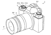
図1は、本発明の実施の形態1にかかる撮像装置の被写体に面する側(前面側)の構成を示す図である。図2は、本発明の実施の形態1にかかる撮像装置の撮影者に面する側(背面側)の構成を示す図である。図3は、本発明の実施の形態1にかかる撮像装置の機能構成を示すブロック図である。 FIG. 1 is a diagram illustrating a configuration of a side facing the subject (front side) of the imaging apparatus according to the first embodiment of the present invention. FIG. 2 is a diagram illustrating a configuration of a side facing the photographer (back side) of the imaging apparatus according to the first embodiment of the present invention. FIG. 3 is a block diagram illustrating a functional configuration of the imaging apparatus according to the first embodiment of the present invention.
図1〜図3に示す撮像装置1は、本体部2と、本体部2に着脱自在であり、所定の視野領域から光を集光するとともに、光学ズームが可能なレンズ部3と、本体部2に着脱自在な外部機器4と、を備える。
The imaging apparatus 1 shown in FIGS. 1 to 3 is detachable from the
まず、本体部2について説明する。本体部2は、シャッタ201と、シャッタ駆動部202と、撮像素子203と、撮像素子駆動部204と、信号処理部205と、A/D変換部206と、画像処理部207と、AE処理部208と、AF処理部209と、画像圧縮展開部210と、入力部211と、アクセサリ通信部212と、接眼表示部213と、アイセンサ214と、可動部215と、表示部216と、タッチパネル217と、回動判定部218と、状態検出部219と、時計220と、記録媒体221と、メモリI/F222と、SDRAM(Synchronous Dynamic Random Access Memory)223と、Flashメモリ224と、本体通信部225と、バス226と、本体制御部227と、を備える。
First, the
シャッタ201は、撮像素子203の状態を露光状態または遮光状態に設定する。シャッタ駆動部202は、ステッピングモータやDCモータ等を用いて構成され、本体制御部227から入力される指示信号に応じてシャッタ201を駆動する。
The
撮像素子203は、レンズ部3が集光した光を受光して電気信号に変換するCCD(Charge Coupled Device)またはCMOS(Complementary Metal Oxide Semiconductor)等を用いて構成され、被写体の画像データを生成する。撮像素子駆動部204は、所定のタイミングで撮像素子203から画像データ(アナログ信号)を信号処理部205へ出力させる。この意味で、撮像素子駆動部204は、電子シャッタとして機能する。
The
信号処理部205は、撮像素子203から入力される画像データに対して、アナログ処理を施してA/D変換部206へ出力する。たとえば、信号処理部205は、画像データに対して、リセットノイズ等を低減した上で波形整形後、目的の明るさとなるようにゲインアップを行う。
The
A/D変換部206は、信号処理部205から入力されるアナログの画像データに対してA/D変換を行うことによってデジタルの画像データ(RAWデータ)を生成し、バス226を介してSDRAM223へ出力する。
The A /
画像処理部207は、バス226を介してSDRAM223から画像データ(RAWデータ)を取得し、取得した画像データに対して各種の画像処理を行って処理画像データを生成する。具体的には、画像処理部207は、オプティカルブラック減算処理、ホワイトバランス(WB)調整処理、カラーマトリクス演算処理、ガンマ補正処理、色再現処理およびエッジ強調処理等を含む基本の画像処理を行う。なお、画像処理部207は、撮像素子203がベイヤー配列の場合には画像データの同時化処理を行う。画像処理部207は、バス226を介して処理画像データをSDRAM223または表示部216へ出力する。
The image processing unit 207 acquires image data (RAW data) from the
ここで、画像処理部207の詳細な構成について説明する。画像処理部207は、トリミング部207aと、特徴量検出部207bと、追尾被写体設定部207cと、を有する。
Here, a detailed configuration of the image processing unit 207 will be described. The image processing unit 207 includes a trimming unit 207a, a feature
トリミング部207aは、本体制御部227の制御のもと、画像データに対応する画像の所定の領域を切出してトリミング画像を生成する。また、トリミング部207aは、入力部211から入力される指示信号またはタッチパネル217から入力される位置信号に応じて、レンズ部3による所定のズーム倍率に対応する撮影領域を、撮像素子203が生成する画像データに対応する画像から切出してトリミング画像を生成する。たとえば、トリミング部207aは、タッチパネル217から入力される位置信号を含む領域を、レンズ部3による所定のズーム倍率に対応する撮影領域として画像データから切出してトリミング画像を生成する。この意味で、トリミング部207aが電子ズームとして機能する。
The trimming unit 207a generates a trimmed image by cutting out a predetermined area of the image corresponding to the image data under the control of the main
特徴量検出部207bは、本体制御部227の制御のもと、画像データに対応する画像の所定の領域に含まれる被写体の特徴量を検出する。具体的には、特徴量検出部207bは、入力部211から入力された指示信号またはタッチパネル217から入力される位置信号によって設定された所定の領域に含まれる被写体の輝度成分を特徴量として検出する。
The feature
追尾被写体設定部207cは、特徴量検出部207bが検出した特徴量に基づいて、追尾する追尾被写体を設定し、この設定した追尾被写体を隣接する画像間で追尾する。なお、追尾被写体設定部207cは、パターンマッチング等の周知技術を用いて追尾被写体を隣接する画像間で追尾してもよい。
The tracking
AE処理部208は、バス226を介してSDRAM223に記録された画像データを取得し、取得した画像データに基づいて、撮像装置1が静止画撮影または動画撮影を行う際の露出条件を設定する。具体的には、AE処理部208は、画像データから輝度を算出し、算出した輝度に基づいて、たとえば絞り値、シャッタ速度、ISO感度等を決定することで撮像装置1の自動露出を行う。
The
AF処理部209は、バス226を介してSDRAM223に記録された画像データを取得し、取得した画像データに基づいて、撮像装置1の自動焦点の調整を行う。たとえば、AF処理部209は、画像データから高周波成分の信号を取り出し、高周波成分の信号に対してAF(Auto Focus)演算処理を行うことによって、撮像装置1の合焦評価を決定することで撮像装置1の自動焦点の調整を行う。なお、AF処理部209は、瞳分割位相差法を用いて撮像装置1の自動焦点の調整を行ってもよい。
The
画像圧縮展開部210は、バス226を介してSDRAM223から画像データや処理画像データを取得し、取得した画像データに対して所定の形式に従って圧縮し、この圧縮した画像データをメモリI/F222を介して記録媒体221へ出力する。ここで、所定の形式としては、JPEG(Joint Photographic Experts Group)方式、MotionJPEG方式およびMP4(H.264)方式等である。また、画像圧縮展開部210は、バス226およびメモリI/F222を介して記録媒体221に記録された画像データ(圧縮画像データ)を取得し、取得した画像データを展開(伸長)してSDRAM223へ出力する。
The image compression /
入力部211は、撮像装置1の電源状態をオン状態またはオフ状態に切り替える電源スイッチ211aと、静止画撮影の指示を与える静止画レリーズ信号の入力を受け付けるレリーズスイッチ211bと、撮像装置1の各種設定を切り替える操作スイッチ211cと、撮像装置1の各種設定を表示部216に表示させるメニュースイッチ211dと、動画撮影の指示を与える動画レリーズ信号の入力を受け付ける動画スイッチ211eと、記録媒体221に記録された画像データに対応する画像を表示部216に表示させる再生スイッチ211fと、を有する。レリーズスイッチ211bは、外部からの押圧により進退可能であり、半押しされた場合に撮影準備動作を指示する指示信号のファーストレリーズ信号の入力を受け付ける一方、全押しされた場合に静止画撮影を指示するセカンドレリーズ信号の入力を受け付ける。
The input unit 211 includes a
アクセサリ通信部212は、本体部2に装着される外部機器4との通信を行うための通信インターフェースである。
The
接眼表示部213は、液晶または有機EL(Electro Luminescence)からなる表示パネルおよび駆動ドライバ等を用いて構成される。接眼表示部213は、本体制御部227の制御のもと、バス226を介してSDRAM223に記録された画像データに対応する画像を表示する。この意味で、接眼表示部213は、電子ビューファインダ(EVF)として機能する。
The
アイセンサ214は、接触センサ等を用いて構成される。アイセンサ214は、接眼表示部213に対するユーザの接近を検出し、この検出結果を本体制御部227へ出力する。具体的には、アイセンサ214は、ユーザが接眼表示部213で画像を確認しているか否かを検出する。
The
可動部215は、表示部216およびタッチパネル217が設けられ、ヒンジ215aを介して可動可能に本体部2に設けられる。たとえば、可動部215は、本体部2の鉛直方向に対して表示部216が上向き、または下向きに変更可能に本体部2に設けられる(図2を参照)。
The
表示部216は、液晶または有機ELからなる表示パネルおよび駆動ドライバ等を用いて構成される。表示部216は、本体制御部227の制御のもと、バス226を介してSDRAM223に記録された画像データまたは記録媒体221に記録された画像データを取得し、取得した画像データに対応する画像を表示する。ここで、画像の表示には、撮影直後の画像データを所定時間(たとえば3秒間)だけ表示するレックビュー表示、記録媒体221に記録された画像データを再生する再生表示、および撮像素子203が連続的に生成する画像データに対応するライブビュー画像を時系列に沿って順次表示するライブビュー表示等が含まれる。また、表示部216は、撮像装置1の操作情報および撮影に関する情報を適宜表示する。
The
タッチパネル217は、表示部216の表示画面上に重畳して設けられる。タッチパネル217は、外部からの物体のタッチを検出し、この検出したタッチ位置に応じた位置信号を本体制御部227へ出力する。また、タッチパネル217は、ユーザが表示部216で表示される情報、たとえばアイコン画像やサムネイル画像に基づいてタッチした位置を検出し、この検出したタッチ位置に応じて撮像装置1が行う動作を指示する指示信号や画像を選択する選択信号の入力を受け付けてもよい。一般に、タッチパネル217としては、抵抗膜方式、静電容量方式および光学方式等がある。本実施の形態1では、いずれの方式のタッチパネルであっても適用可能である。さらに、可動部215、表示部216およびタッチパネル217は、一体的に形成してもよい。
The
回動判定部218は、可動部215の回動状況を判定し、この検出結果を本体制御部227へ出力する。たとえば、回動判定部218は、本体部2に対して可動部215が可動しているか否かを判定し、この判定結果を本体制御部227へ出力する。
The
状態検出部219は、加速度センサおよびジャイロセンサを用いて構成され、撮像装置1に生じる加速度および角速度をそれぞれ検出し、この検出結果を本体制御部227へ出力する。
The
時計220は、計時機能および撮影日時の判定機能を有する。時計220は、撮像素子203によって撮像された画像データに日時データを付加するため、日時データを本体制御部227へ出力する。
The
記録媒体221は、撮像装置1の外部から装着されるメモリカード等を用いて構成される。記録媒体221は、メモリI/F222を介して撮像装置1に着脱自在に装着される。記録媒体221には、画像処理部207や画像圧縮展開部210が処理を施した画像データが書き込まれる。また、記録媒体221は、本体制御部227によって記録された画像データが読み出される。
The
SDRAM223は、揮発メモリを用いて構成される。SDRAM223は、バス226を介してA/D変換部206から入力される画像データ、画像処理部207から入力される画像データおよび撮像装置1の処理中の情報を一時的に記録する。たとえば、SDRAM223は、信号処理部205、A/D変換部206およびバス226を介して撮像素子203が1フレーム毎に順次出力する画像データを一時的に記録する。
The
Flashメモリ224は、不揮発性メモリを用いて構成される。Flashメモリ224は、プログラム記録部224aを有する。プログラム記録部224aは、撮像装置1を動作させるための各種プログラムおよびプログラムの実行中に使用される各種データおよび画像処理部207による画像処理の動作に必要な各画像処理のパラメータ等を記録する。
The
本体通信部225は、本体部2に装着されるレンズ部3との通信を行うための通信インターフェースである。
The main
バス226は、撮像装置1の各構成部位を接続する伝送路等を用いて構成される。バス226は、撮像装置1の内部で発生した各種データを撮像装置1の各構成部に転送する。
The
本体制御部227は、CPU(Central Processing Unit)等を用いて構成される。本体制御部227は、入力部211からの指示信号またはタッチパネル217からの位置信号に応じて撮像装置1を構成する各部に対応する指示やデータの転送等を行って撮像装置1の動作を統括的に制御する。
The main
本体制御部227の詳細な構成について説明する。本体制御部227は、タッチ検出部227aと、撮影制御部227bと、表示制御部227cと、を有する。
A detailed configuration of the main
タッチ検出部227aは、タッチパネル217から入力される位置信号に応じて、タッチパネル217上のタッチ位置を検出する。
The
撮影制御部227bは、レリーズスイッチ211bからセカンドレリーズ信号が入力された場合、撮像装置1における撮影動作を開始する制御を行う。ここで、撮像装置1における撮影動作とは、シャッタ駆動部202および撮像素子駆動部204の駆動によって撮像素子203が出力した画像データに対し、信号処理部205、A/D変換部206および画像処理部207が所定の処理を施す動作をいう。このように処理が施された画像データは、撮影制御部227bの制御のもと、画像圧縮展開部210で圧縮され、バス226およびメモリI/F222を介して記録媒体221に記録される。また、撮影制御部227bは、タッチパネル217から位置信号が入力された場合、トリミング部207aが生成したトリミング画像に対応するズーム倍率に従って、レンズ部3の光学ズームを制御する。具体的には、撮影制御部227bは、本体通信部225を介しレンズ部3を制御することによって、トリミング部207aが生成したトリミング画像のズーム倍率になるようにレンズ部3の光学ズームを駆動する。
When the second release signal is input from the
表示制御部227cは、画像データに対応する画像を表示部216および/または接眼表示部213に表示させる。具体的には、表示制御部227cは、接眼表示部213の電源がオン状態である場合、画像データに対応するライブビュー画像を接眼表示部213に表示させる一方、接眼表示部213の電源がオフ状態である場合、画像データに対応するライブビュー画像を表示部216に表示させる。また、表示制御部227cは、レンズ部3による所定のズーム倍率に対応する撮影領域に関するズーム情報およびトリミング部207aが生成したトリミング画像をライブビュー画像上に重畳して接眼表示部213および/または表示部216に表示させる。ここで、撮影領域とは、レンズ部3の焦点距離と撮像素子203のセンササイズとによって定まる画角(視野領域)である。なお、表示制御部227cは、レンズ部3の光軸Oに関する指標をライブビュー画像上に重畳して表示部216に表示させてもよい。
The display control unit 227c causes the
以上の構成を有する本体部2に対して、音声入出力機能、フラッシュ機能および外部と双方向に通信可能な通信機能等を具備させてもよい。
The
つぎに、レンズ部3について説明する。レンズ部3は、ズームレンズ301と、ズーム駆動部302と、ズーム位置検出部303と、絞り304と、絞り駆動部305と、絞り値検出部306と、フォーカスレンズ307と、フォーカス駆動部308と、フォーカス位置検出部309と、レンズ操作部310と、レンズFlashメモリ311と、レンズ通信部312と、レンズ制御部313と、を備える。
Next, the
ズームレンズ301は、一または複数のレンズを用いて構成される。ズームレンズ301は、レンズ部3の光軸O上に沿って移動することにより、撮像装置1の光学ズームの倍率を変更する。たとえば、ズームレンズ301は、焦点距離が12mm〜50mmの間で焦点距離を変更することができる。
The
ズーム駆動部302は、DCモータまたはステッピングモータ等を用いて構成され、レンズ制御部313の制御のもと、ズームレンズ301を光軸O上に沿って移動させることにより、撮像装置1の光学ズームの変更を行う。
The
ズーム位置検出部303は、フォトインタラプタ等を用いて構成され、光軸O上におけるズームレンズ301の位置を検出し、この検出結果をレンズ制御部313へ出力する。
The zoom
絞り304は、ズームレンズ301が集光した光の入射量を制限することにより露出の調整を行う。
The
絞り駆動部305は、ステッピングモータ等を用いて構成され、レンズ制御部313の制御のもと、絞り304を駆動することにより、撮像装置1の絞り値(F値)を変更する。
The
絞り値検出部306は、フォトインタラプタやエンコーダ等を用いて構成され、絞り304の現在の状況から絞り値を検出し、この検出結果をレンズ制御部313へ出力する。
The aperture
フォーカスレンズ307は、一または複数のレンズを用いて構成される。フォーカスレンズ307は、レンズ部3の光軸O上に沿って移動することにより、撮像装置1のピント位置を変更する。
The
フォーカス駆動部308は、DCモータやステッピングモータ等を用いて構成され、レンズ制御部313の制御のもと、フォーカスレンズ307を光軸Oに沿って移動させることにより、撮像装置1のピント位置を調整する。
The
フォーカス位置検出部309は、フォトインタラプタ等を用いて構成され、光軸O上におけるフォーカスレンズ307の位置を検出し、この検出結果をレンズ制御部313へ出力する。
The focus
レンズ操作部310は、図1に示すように、レンズ部3のレンズ鏡筒の周囲に設けられるリングであり、レンズ部3における光学ズームの変更を指示する指示信号の入力またはレンズ部3におけるピント位置の調整を指示する指示信号の入力を受け付ける。なお、レンズ操作部310は、プッシュ式のスイッチやレバー式のスイッチ等であってもよい。
As shown in FIG. 1, the
レンズFlashメモリ311は、ズームレンズ301、絞り304およびフォーカスレンズ307の位置および動きをそれぞれ決定するための制御プログラム、レンズ部3のレンズ特性および各種パラメータを記録する。ここで、レンズ特性とは、レンズ部3の色収差、画角情報、明るさ情報(f値)および焦点距離情報(たとえば50mm〜300mm)である。
The
レンズ通信部312は、レンズ部3が本体部2に装着された際に、本体部2の本体通信部225と通信を行うための通信インターフェースである。
The
レンズ制御部313は、CPU等を用いて構成される。レンズ制御部313は、レンズ操作部310からの指示信号または本体部2からの指示信号に応じてレンズ部3の動作を制御する。具体的には、レンズ制御部313は、レンズ操作部310からの指示信号に応じて、フォーカス駆動部308を駆動させてフォーカスレンズ307によるピント調整やズーム駆動部302を駆動させてズームレンズ301の光学ズームのズーム倍率の変更を行う。なお、レンズ制御部313は、レンズ部3が本体部2に装着された際に、レンズ部3のレンズ特性およびレンズ部3を識別する識別情報を本体部2に送信してもよい。
The
つぎに、外部機器4について説明する。外部機器4は、本体部2に着脱自在である。外部機器4は、たとえばフラッシュ装置、音声入出力可能な録音装置、所定の方式に従って外部のネットワークに接続して記録媒体221に記録された画像データを外部へ転送する通信装置である。また、外部機器4は、通信部401を有する。通信部401は、外部機器4が本体部2に装着された際に、本体部2のアクセサリ通信部212と通信を行うための通信インターフェースである。
Next, the
以上の構成を有する撮像装置1が実行する処理について説明する。図4は、撮像装置1が実行する処理の概要を示すフローチャートである。 Processing executed by the imaging apparatus 1 having the above configuration will be described. FIG. 4 is a flowchart illustrating an outline of processing executed by the imaging apparatus 1.
まず、撮像装置1が撮影モードに設定されている場合(ステップS101:Yes)について説明する。この場合において、レンズ部3が他のレンズ部3に交換されたとき(ステップS102:Yes)、本体制御部227は、交換されたレンズ部3とレンズ通信を行って、レンズ部3からレンズ特性を取得する(ステップS103)。その後、撮像装置1は、ステップS104へ移行する。これに対して、レンズ部3が他のレンズ部3に交換されていない場合(ステップS102:No)、撮像装置1は、ステップS104へ移行する。
First, the case where the imaging device 1 is set to the shooting mode (step S101: Yes) will be described. In this case, when the
続いて、表示制御部227cは、撮像素子203が生成した画像データに対応するライブビュー画像、ライブビュー画像内において拡大する領域の候補を示すズーム枠、およびトリミング部207aが画像データからズーム枠に対応する領域を切出した副画像を表示部216または接眼表示部213に表示させる(ステップS104)。たとえば、図5に示すように、ユーザが撮像装置1を用いて天体を撮影する場合、表示制御部227cは、表示部216または接眼表示部213が表示するライブビュー画像W1に、拡大する領域を示すズーム枠K1およびトリミング部207aが画像データからズーム枠K1に対応する領域を切出して生成した副画像K2を重畳して表示させる。なお、図5においては、ズーム枠K1は、初期状態としてレンズ部3の所定のズーム倍率、たとえば2倍のズーム倍率に対応した撮影領域を示す。また、副画像K2の表示位置や大きさは、適宜変更することができる。
Subsequently, the display control unit 227c displays a live view image corresponding to the image data generated by the
その後、タッチ検出部227aは、表示部216が表示するライブビュー画像の画面内でタッチされたか否かを検出する(ステップS105)。具体的には、図6に示すように、タッチ検出部227aは、ユーザによって表示部216が表示するライブビュー画像W1内の画面内でタッチされることにより、タッチパネル217から位置信号が入力されたか否かを検出する。タッチ検出部227aが表示部216によって表示されるライブビュー画像W1の画面内でタッチを検出した場合(ステップS105:Yes)、撮像装置1は、後述するステップS122へ移行する。これに対して、タッチ検出部227aがタッチパネル217を介して表示部216によって表示されるライブビュー画像W1の画面内でタッチを検出していない場合(ステップS105:No)、撮像装置1は、後述するステップS106へ移行する。
Thereafter, the
ステップS106において、タッチ検出部227aは、ズーム枠K1に対してピンチ操作が行われたか否かを検出する。具体的には、図7に示すように、タッチ検出部227aは、ユーザがズーム枠K1の境界を含む領域内で異なる2箇所にタッチすることにより、タッチパネル217から異なるタッチ位置を示す2つの位置信号が入力されたか否かを検出する。なお、図7においては、タッチ検出部227aは、2箇所にタッチされることによりピンチ操作を判定しているが、たとえばズーム枠K1の枠上にタッチされた場合であっても、ピンチ操作が行われたと検出してもよい。タッチ検出部227aがズーム枠K1に対してピンチ操作を検出した場合(ステップS106:Yes)、撮像装置1は、後述するステップS107へ移行する。これに対して、タッチ検出部227aがズーム枠K1に対してピンチ操作を検出していない場合(ステップS106:No)、撮像装置1は、後述するステップS110へ移行する。
In step S106, the
ステップS107において、レンズ部3による光学ズームが限界の場合(ステップS107:Yes)、表示制御部227cは、表示部216が表示するライブビュー画像W1上に、レンズ部3による光学ズームが限界であることを示す警告を表示させる(ステップS108)。たとえば、表示制御部227cは、ズーム枠K1の表示をハイライト表示で表示させることにより、レンズ部3による光学ズームが限界であることを示す警告を表示部216に表示させる。なお、表示制御部227cは、レンズ部3による光学ズームが限界であることを示す警告をアイコン画像や文字で表示部216に表示させてもよい。ステップS108の後、撮像装置1は、ステップS110へ移行する。
In step S107, when the optical zoom by the
ステップS107において、レンズ部3による光学ズームが限界でない場合(ステップS107:No)、表示制御部227cは、タッチパネル217から入力された2つの位置信号に応じて、ライブビュー画像W1上におけるズーム枠K1の表示領域を拡大または縮小する(ステップS109)。具体的には、表示制御部227cは、異なる2つの位置人号を示す2点のタッチ位置が時間の経過とともに離れる場合(ピンチアウト操作があった場合)、ズーム枠K1の表示領域を大きくする一方、異なる2つの位置信号を示す2点のタッチ位置が時間の経過とともに近づく場合(ピンチイン操作があった場合)、ズーム枠K1の表示領域を小さくする。ステップS109の後、撮像装置1は、ステップS110へ移行する。
In step S107, when the optical zoom by the
続いて、タッチ検出部227aは、ズーム枠K1に対してスライド操作が行われたか否かを検出する(ステップS110)。具体的には、タッチ検出部227aは、ユーザがズーム枠K1の境界を含む領域内でタッチしながらタッチ位置を移動させることにより、タッチパネル217からタッチ位置を示す位置信号が時間の経過とともに変化しているか否かを検出する。タッチ検出部227aがズーム枠K1に対してスライド操作を検出した場合(ステップS110:Yes)、表示制御部227cは、スライド操作に応じてライブビュー画像W1上におけるズーム枠K1を移動して表示部216に表示させる(ステップS111)。ステップS111の後、撮像装置1は、ステップS112へ移行する。これに対して、タッチ検出部227aがズーム枠K1に対してスライド操作を検出していない場合(ステップS110:No)、撮像装置1は、ステップS112へ移行する。
Subsequently, the
その後、副画像K2に対してタップ操作があった場合(ステップS112:Yes)において、ズーム枠K1がライブビュー画像W1上の画面の中心を含む位置にあるとき(ステップS113:Yes)、撮影制御部227bは、レンズ部3の光学ズームを、ズーム枠K1に相当する大きさまでレンズ部3の光学ズームのズーム倍率を変更する(ステップS114)。具体的には、図8に示すように、ユーザがタッチパネル217を介して副画像K2にタップ操作を行った場合において、ズーム枠K1がライブビュー画像W1上の画面の中心の位置であって、レンズ部3の光軸O上を一部に含む位置にあるとき(図8(a))、撮影制御部227bは、本体通信部225およびレンズ通信部312を介してレンズ制御部313を制御し、ズーム駆動部302を駆動することによって、ズームレンズ301を光軸O方向に沿って移動させることで、ズーム枠K1のズーム倍率に相当する大きさまでレンズ部3の光学ズームのズーム倍率を徐々に変更する(図8(a)→図8(b))。これにより、撮像装置1は、ユーザが所望する領域に対して、光学ズームのズーム倍率を変更しながら拡大または縮小することができる。なお、撮像装置1が光学ズームを行っている際に、タッチパネル217から位置信号の入力が停止した場合、撮影制御部227bは、現在のズーム倍率の位置でズームレンズ301の駆動を停止させてもよい。また
レンズ部3が光学ズームを行っている場合において、撮影制御部227bは、レンズ部3がズーム枠K1のズーム倍率に相当する大きさのズーム倍率に到達するまで、トリミング部207aにトリミング画像を順次生成させ、表示制御部227cは、トリミング部207aが生成したトリミング画像を表示部216に表示させてもよい。これにより、レンズ部3による光学ズームが到達するまでの期間を、仮想的にズーム枠K1のズーム倍率に相当するズーム倍率で表示することができ、ユーザが所望する領域を瞬時に拡大または縮小することができる。
Thereafter, when there is a tap operation on the sub-image K2 (step S112: Yes), when the zoom frame K1 is at a position including the center of the screen on the live view image W1 (step S113: Yes), shooting control is performed. The unit 227b changes the optical zoom of the
続いて、レリーズスイッチ211bが全押しされることによって、セカンドレリーズ信号が入力されて撮影操作が行われた場合(ステップS115:Yes)、撮影制御部227bは、撮像素子203に静止画撮影を実行させ(ステップS116)、撮像素子203が生成した画像データを記録媒体221に記録する(ステップS117)。この際、表示制御部227cは、画像データに対応する画像を所定時間(たとえば3秒間)だけ表示部216にレックビュー表示させてもよい。これに対して、レリーズスイッチ211bを介して撮影操作が行われていない場合(ステップS115:No)、撮像装置1は、ステップS118へ移行する。
Subsequently, when the
その後、電源スイッチ211aが操作されることにより、撮像装置1の電源がオフになった場合(ステップS118:Yes)、撮像装置1は、本処理を終了する。これに対して、電源スイッチ211aを介して撮像装置1の電源がオフになっていない場合(ステップS118:No)、撮像装置1は、ステップS101へ戻る。
Thereafter, when the power supply of the imaging device 1 is turned off by operating the
ステップS112において、副画像K2に対してタップ操作があった場合(ステップS112:Yes)において、ズーム枠K1がライブビュー画像W1の画面の中央にないとき(ステップS113:No)、撮影制御部227bは、ズーム枠K1のズーム倍率に相当する大きさのトリミング画像をトリミング部207aに生成させることによって、ズーム枠K1のズーム倍率に相当する大きさまで電子ズームを行う(ステップS119)。たとえば、図9に示すように、ユーザがタッチパネル217を介して副画像K3にタップ操作を行った場合において、ズーム枠K1がライブビュー画像W1上の画面の中央にないとき(図9(a))、撮影制御部227bがズーム枠K1のズーム倍率に相当する大きさのトリミング画像をトリミング部207aに生成させ、表示制御部227cがトリミング部207aによって生成されたトリミング画像W2を表示部216に全画面表示させる(図9(a)→図9(b))。これにより、撮像装置1は、レンズ部3による光学ズームができなくとも、電子ズームによってユーザが所望する領域に対して拡大または縮小することができる。ステップS119の後、撮像装置1は、ステップS115へ移行する。
In step S112, when the tap operation is performed on the sub image K2 (step S112: Yes), when the zoom frame K1 is not at the center of the screen of the live view image W1 (step S113: No), the shooting control unit 227b. The electronic zoom is performed to a size corresponding to the zoom magnification of the zoom frame K1 by causing the trimming unit 207a to generate a trimming image having a size corresponding to the zoom magnification of the zoom frame K1 (step S119). For example, as shown in FIG. 9, when the user performs a tap operation on the sub image K3 via the
ステップS112において、タッチパネル217を介してズーム枠K1のタップ操作がなく(ステップS112:No)、レリーズスイッチ211bの半押し操作が行われた場合(ステップS120:Yes)、撮像装置1は、ステップS113へ移行する。これに対して、タッチパネル217を介してズーム枠K1のタップ操作がなく(ステップS112:No)、レリーズスイッチ211bの半押し操作が行われていない場合(ステップS120:No)、撮像装置1は、ステップS121へ移行する。
In step S112, when there is no tap operation of the zoom frame K1 via the touch panel 217 (step S112: No) and the half-press operation of the
ステップS121において、本体制御部227は、表示部216が表示するライブビュー画像W1上において、追尾被写体が画面中央に位置しているか否かを判断する。具体的には、本体制御部227は、追尾被写体設定部207cが設定した追尾被写体がライブビュー画像W1上の画面中央の領域内であって、ズーム枠K1内の領域内に位置しているか否かを判断する。表示部216が表示するライブビュー画像W1上において、追尾被写体が画面中央に位置している場合(ステップS121:Yes)、撮像装置1は、ステップS113へ移行する。これに対して、表示部216が表示するライブビュー画像W1上において、追尾被写体が画面中央に位置していない場合(ステップS121:No)、撮像装置1は、ステップS115へ移行する。
In step S121, the main
ステップS122において、撮影制御部227bは、タッチ位置に対応する領域にレンズ部3のピントを調整する。具体的には、撮影制御部227bは、本体通信部225およびレンズ通信部312を介してレンズ制御部313を制御し、フォーカス駆動部308を駆動することにより、フォーカスレンズ307を光軸O方向に沿って移動させることで、タッチ位置に対応する領域にレンズ部3のピントを調整する。ステップS122の後、撮像装置1は、ステップS116へ移行する。
In step S122, the imaging control unit 227b adjusts the focus of the
ステップS101において、撮像装置1が撮影モードに設定されておらず(ステップS101:No)、撮像装置1が再生モードに設定されている場合(ステップS123:Yes)について説明する。この場合、表示制御部227cは、記録媒体221に記録された画像データを表示部216に表示させて再生する(ステップS124)。
In step S101, the case where the imaging device 1 is not set to the shooting mode (step S101: No) and the imaging device 1 is set to the reproduction mode (step S123: Yes) will be described. In this case, the display control unit 227c causes the
続いて、画像を変更する変更操作があった場合(ステップS125:Yes)、表示制御部227cは、画像を変更する(ステップS126)。その後、撮像装置1は、ステップS124へ戻る。これに対して、画像を変更する変更操作がない場合(ステップS125:No)、撮像装置1は、ステップS118へ移行する。 Subsequently, when there is a change operation for changing the image (step S125: Yes), the display control unit 227c changes the image (step S126). Thereafter, the imaging apparatus 1 returns to step S124. On the other hand, when there is no change operation which changes an image (step S125: No), the imaging device 1 transfers to step S118.
ステップS123において、撮像装置1が再生モードに設定されていない場合(ステップS123:No)、撮像装置1は、ステップS118へ移行する。 In step S123, when the imaging device 1 is not set to the reproduction mode (step S123: No), the imaging device 1 proceeds to step S118.
以上説明した本実施の形態1によれば、トリミング部207aがレンズ部3による所定のズーム倍率に対応する撮影領域を、撮像素子203によって生成された画像データから切出してトリミング画像を生成し、撮影制御部227bがトリミング部207aによって生成されたトリミング画像に対応するズーム倍率に従って、レンズ部3の光学ズームを制御する。これにより、画像の解像度を低下させることなく、直感的な操作でユーザが所望する領域を拡大して表示することができる。
According to the first embodiment described above, the trimming unit 207a cuts out an imaging region corresponding to a predetermined zoom magnification by the
さらに、本実施の形態1によれば、表示制御部227cがレンズ部3によるズーム領域に関する情報としてズーム枠K1およびトリミング部207aによって生成されたトリミング画像を副画像としてライブビュー画像W1に重畳して表示部216に表示させる。これにより、ユーザは、所望するズーム倍率の画像を確認しながら、所望のズーム倍率に変更することができる。
Furthermore, according to the first embodiment, the display control unit 227c superimposes the trimming image generated by the zoom frame K1 and the trimming unit 207a as the sub-image on the live view image W1 as information on the zoom region by the
また、本実施の形態1によれば、タッチパネル217を介してズーム枠の位置または大きさを変更することができるので、直感的な操作でレンズ部3の光学ズームを行うことができる。
Further, according to the first embodiment, since the position or size of the zoom frame can be changed via the
さらにまた、本実施の形態1によれば、タッチパネル217を介して副画像K2がタッチされた場合または入力部211からレンズ部3による光学ズームを指示する指示信号が入力された場合、撮影制御部227bがズーム枠K1のズーム倍率に相当する大きさまでレンズ部3に光学ズームを実行させる。これにより、ユーザは、直感的に操作で所望の光学ズームを行うことができる。
Furthermore, according to the first embodiment, when the sub image K2 is touched via the
また、本実施の形態1によれば、レンズ部3の光軸O上にズーム枠がない場合、表示制御部227cは、トリミング部207aが生成したトリミング画像K3を表示部216に全画面表示させる。これにより、レンズ部3による光学ズームを行うことができなくとも、電子ズームによって仮想的にユーザが所望するズーム倍率で表示することができる。
Further, according to the first embodiment, when there is no zoom frame on the optical axis O of the
また、本実施の形態1によれば、表示制御部227cは、レンズ部3の光学ズームによる撮影領域よりズーム枠K1がより大きい場合、トリミング部207aが生成したトリミング画像を表示部216に全画面表示させる。これにより、レンズ部3による光学ズームを行うことができなくとも、電子ズームによって仮想的にユーザが所望するズーム倍率で表示部216に画像を表示することができる。
Further, according to the first embodiment, when the zoom frame K1 is larger than the photographing area by the optical zoom of the
(実施の形態2)
つぎに、本発明の実施の形態2について説明する。本実施の形態2にかかる撮像装置は、上述した実施の形態1にかかる撮像装置と同様の構成を有する。このため、以下においては、本実施の形態2にかかる撮像装置が実行する処理について説明する。なお、上述した実施の形態1と同一の構成には同一の符号を付して説明する。
(Embodiment 2)
Next, a second embodiment of the present invention will be described. The imaging apparatus according to the second embodiment has the same configuration as the imaging apparatus according to the first embodiment described above. Therefore, in the following, processing executed by the imaging apparatus according to the second embodiment will be described. In addition, the same code | symbol is attached | subjected and demonstrated to the structure same as Embodiment 1 mentioned above.
図10は、本実施の形態2にかかる撮像装置1が実行する処理の概要を示すフローチャートである。 FIG. 10 is a flowchart illustrating an outline of processing executed by the imaging apparatus 1 according to the second embodiment.
まず、撮像装置1が撮影モードに設定されている場合(ステップS201:Yes)について説明する。この場合、本体制御部227は、本体通信部225およびレンズ通信部312を介してレンズ制御部313とレンズ通信を行う(ステップS202)。この際、本体制御部227は、レンズ部3からレンズ特性を取得する。
First, the case where the imaging device 1 is set to the shooting mode (step S201: Yes) will be described. In this case, the main
続いて、撮影制御部227bは、撮像素子駆動部204を駆動することにより、撮像素子203に撮像を実行させる(ステップS203)。
Subsequently, the imaging control unit 227b drives the imaging
その後、表示制御部227cは、撮像素子203が生成した画像データに対応するライブビュー画像を表示部216に表示させる(ステップS204)。
Thereafter, the display control unit 227c causes the
続いて、表示部216が表示するライブビュー画像上にズーム枠表示がある場合(ステップS205:Yes)、撮像装置1は、後述するステップS210へ移行する。これに対して、表示部216が表示するライブビュー画像上にズーム枠表示がない場合(ステップS205:No)、撮像装置1は、後述するステップS206へ移行する。 Subsequently, when there is a zoom frame display on the live view image displayed by the display unit 216 (step S205: Yes), the imaging device 1 proceeds to step S210 to be described later. On the other hand, when there is no zoom frame display on the live view image displayed by the display unit 216 (step S205: No), the imaging apparatus 1 proceeds to step S206 described later.
ステップS206において、タッチ検出部227aは、タッチパネル217がタッチされたか否かを検出する。タッチ検出部227aがタッチパネル217のタッチを検出した場合(ステップS206:Yes)、撮像装置1は、後述するステップS207へ移行する。これに対して、タッチ検出部227aがタッチパネル217のタッチを検出した場合(ステップS206:No)、撮像装置1は、後述するステップS210へ移行する。
In step S206, the
ステップS207において、表示制御部227cは、タッチ位置の座標を取得し(ステップS207)、ライブビュー画像上にズーム枠を表示部216に表示させるとともに(ステップS208)、副画像をライブビュー画像上に重畳して表示部216に表示させる(ステップS209)。具体的には、図11に示すように、タッチパネル217を介して表示部216が表示するライブビュー画像W10上でタッチされた場合、表示制御部227cは、2つのタッチ位置の対角線の位置を含む領域に対してズーム枠K10を表示させるとともに、トリミング部207aが画像データからズーム枠K10の領域を切出して生成した副画像K11をライブビュー画像W10上の右部に重畳して表示させる。これにより、ユーザは、ズーム後の撮影領域と、ズーム後の画像を把握することができる。ステップS209の後、撮像装置1は、ステップS210へ移行する。
In step S207, the display control unit 227c acquires the coordinates of the touch position (step S207), displays a zoom frame on the live view image on the display unit 216 (step S208), and displays the sub image on the live view image. The information is superimposed and displayed on the display unit 216 (step S209). Specifically, as illustrated in FIG. 11, when touched on the live view image W10 displayed on the
ここで、表示制御部227cがズーム枠K10をライブビュー画像W10上に重畳して表示する際の表示領域の算出方法について説明する。図12は、表示制御部227cがズーム枠K10をライブビュー画像W10上に重畳して表示する際の表示領域の算出方法の概要を説明する図である。図12において、表示部216の左下を原点とし、表示部216の横方向をX軸とし、表示部216の縦方向をY軸とする座標系として考える。
Here, a method of calculating the display area when the display control unit 227c displays the zoom frame K10 superimposed on the live view image W10 will be described. FIG. 12 is a diagram illustrating an outline of a display area calculation method when the display control unit 227c displays the zoom frame K10 in a superimposed manner on the live view image W10. In FIG. 12, a coordinate system is considered in which the lower left of the
図12に示すように、表示部216のX軸方向の大きさをX(f)、ズーム枠のX軸方向の大きさをX(fmax)、現在のレンズ部3の焦点距離をF、レンズ部3の最大焦点距離をFmaxとした場合、以下の式(1)によってズーム枠のX軸方向の表示範囲が算出される。
X(fmax)=(X(f)×F)/Fmax ・・・(1)
また、表示部216のY軸方向の大きさをY(f)、ズーム枠のY軸方向の大きさをY(fmax)、現在のレンズ部3の焦点距離をF、レンズ部3の最大焦点距離をFmaxとした場合、以下の式(2)によってズーム枠のX軸方向の表示範囲が算出される。
Y(fmax)=(Y(f)×F)/Fmax ・・・(2)
このように、表示制御部227cは、式(1)および式(2)を用いて、ライブビュー画像W10上におけるズーム枠K10の表示領域の大きさX(fmax),Y(fmax)を算出する。
As shown in FIG. 12, the size of the
X (fmax) = (X (f) × F) / Fmax (1)
The size of the
Y (fmax) = (Y (f) × F) / Fmax (2)
In this way, the display control unit 227c calculates the sizes X (fmax) and Y (fmax) of the display area of the zoom frame K10 on the live view image W10 using the expressions (1) and (2). .
図10に戻り、ステップS210以降の説明を続ける。ステップS210において、タッチ検出部227aは、ズーム枠K10に対してスライド操作が行われたか否かを検出する。タッチ検出部227aがズーム枠K10に対するスライド操作を検出した場合(ステップS210:Yes)、撮像装置1は、後述するステップS211へ移行する。これに対して、タッチ検出部227aがズーム枠K10に対するスライド操作を検出していない場合(ステップS210:No)、撮像装置1は、後述するステップS214へ移行する。
Returning to FIG. 10, the description from step S210 is continued. In step S210, the
ステップS211において、表示制御部227cは、スライド操作が行われた開始位置からスライド操作が終了してユーザの指がタッチパネル217から離間した位置を示すスライド座標を取得し(ステップS211)、ライブビュー画像W10上に、スライド座標に応じたズーム枠K10を表示部216に表示させるとともに(ステップS212)、副画像K11をライブビュー画像W10上に重畳して表示部216に表示させる(ステップS213)。たとえば、図13に示すように、表示制御部227cは、ズーム枠K10に対してズーム倍率を拡大するスライド操作が行われた場合、スライド操作に応じてズーム枠K10の表示領域を縮小して表示部216に表示させるとともに、トリミング部207aが画像データからズーム枠K10の領域を切出して生成した副画像K11をライブビュー画像W10に重畳して表示部216に表示させる。これにより、ユーザは、ズーム後の撮影領域と、ズーム後の画像を把握することができる。ステップS213の後、撮像装置1は、ステップS214へ移行する。
In step S211, the display control unit 227c acquires the slide coordinates indicating the position where the user's finger is separated from the
図10に戻り、ステップS214以降の説明を続ける。ステップS214において、レリーズスイッチ211bに対して半押し操作があった場合(ステップS214:Yes)において、表示部216が表示するライブビュー画像W10上にズーム枠K10が表示されているとき(ステップS215:Yes)、表示制御部227cは、ライブビュー画像W10上から副画像K11を削除する(ステップS216)。
Returning to FIG. 10, the description from step S214 is continued. In step S214, when the
続いて、撮影制御部227bは、ズーム枠K1に相当する大きさまで光学ズームをレンズ部3に実行させる(ステップS217)。具体的には、撮影制御部227bは、ライブビュー画像W10上におけるズーム枠K10の表示領域に対応するレンズ部3の焦点距離に換算し、この換算した焦点距離になるようにレンズ部3を駆動する。
Subsequently, the imaging control unit 227b causes the
ここで、撮影制御部227bがズーム枠K10の表示領域に対応する焦点距離に換算する算出方法について説明する。図14は、撮影制御部227bがズーム枠K10の表示領域に対応する焦点距離に換算する換算方法の概要を説明する図である。図14において、表示部216の左下を原点とし、表示部216の横方向をX軸とする。
Here, a calculation method in which the shooting control unit 227b converts to a focal length corresponding to the display area of the zoom frame K10 will be described. FIG. 14 is a diagram illustrating an outline of a conversion method in which the imaging control unit 227b converts to a focal length corresponding to the display area of the zoom frame K10. In FIG. 14, the lower left of the
図14に示すように、表示部216のX軸方向の大きさをX(f)、スライド操作後のズーム枠K10のX軸方向の大きさをX(fmin)、現在のレンズ部3の焦点距離をFとした場合、スライド操作後のレンズ部3の焦点距離をFminは、以下の式(3)によって算出される。
Fmin=(X(f)×F)/X(fmin) ・・・(3)
このように、撮影制御部227bは、式(3)を用いて、ライブビュー画像W10上におけるズーム枠K10の表示領域に対応するレンズ部3の焦点距離Fminに換算する。これにより、図15に示すように、撮影制御部227bは、本体通信部225およびレンズ通信部312を介してレンズ制御部313を制御し、式(3)を用いて算出したレンズ部3の焦点距離Fminに基づいて、ズーム駆動部302を駆動することにより、ズームレンズ301を光軸O上に沿って移動させ、ズーム枠K10に相当する光学ズームのズーム倍率に変更する。
As shown in FIG. 14, the size of the
Fmin = (X (f) × F) / X (fmin) (3)
As described above, the imaging control unit 227b converts the focal length Fmin of the
ステップS217の後または表示部216が表示するライブビュー画像W10上にズーム枠K10が表示されていない場合(ステップS215:No)、撮像装置1は、ステップS218へ移行する。 If the zoom frame K10 is not displayed after step S217 or on the live view image W10 displayed by the display unit 216 (step S215: No), the imaging device 1 proceeds to step S218.
続いて、撮影制御部227bは、AE処理部208にAE処理を実行させるとともに、AF処理部209にAF処理を実行させる(ステップS218)。ステップS218の後またはレリーズスイッチ211bに対して半押し操作がない場合(ステップS214:No)、撮像装置1は、ステップS219へ移行する。
Subsequently, the imaging control unit 227b causes the
その後、レリーズスイッチ211bの全押し操作されることにより、撮影操作が行われた場合(ステップS219:Yes)、撮影制御部227bは、撮像素子203に静止画撮影を実行させる(ステップS220)。
Thereafter, when a shooting operation is performed by fully pressing the
続いて、撮影制御部227bは、撮像素子203が生成した画像データを記録媒体221に記録する(ステップS221)。
Subsequently, the imaging control unit 227b records the image data generated by the
その後、電源スイッチ211aが操作されることにより、撮像装置1の電源がオフになった場合(ステップS222:Yes)、撮像装置1は、本処理を終了する。これに対して、電源スイッチ211aが操作されることにより、撮像装置1の電源がオフになっていない場合(ステップS222:No)、撮像装置1は、ステップS201へ戻る。
Thereafter, when the power supply of the imaging apparatus 1 is turned off by operating the
ステップS219において、レリーズスイッチ211bの撮影操作が行われていない場合(ステップS219:No)、撮像装置1は、ステップS222へ移行する。
In step S219, when the shooting operation of the
ステップS201において、撮像装置1が撮影モードに設定されていない場合(ステップS201:No)について説明する。この場合、撮像装置1は、記録媒体221に記録された画像データに対応する画像を表示部216に表示させて再生する画像再生処理を実行する(ステップS223)。その後、撮像装置1は、ステップS222へ移行する。
In step S201, the case where the imaging device 1 is not set to the shooting mode (step S201: No) will be described. In this case, the imaging apparatus 1 performs an image reproduction process in which an image corresponding to the image data recorded on the
以上説明した本実施の形態2によれば、トリミング部207aがレンズ部3による所定のズーム倍率に対応する撮影領域を、撮像素子203によって生成された画像データから切出してトリミング画像を生成し、撮影制御部227bがトリミング部207aによって生成されたトリミング画像のズーム倍率に従って、レンズ部3の光学ズームを制御する。これにより、画像の解像度を低下させることなく、ユーザが直感的な操作で所望の領域を拡大して表示することができる。
According to the second embodiment described above, the trimming unit 207a cuts out an imaging region corresponding to a predetermined zoom magnification by the
(実施の形態3)
つぎに、本発明の実施の形態3について説明する。本実施の形態3にかかる撮像装置は、上述した実施の形態1にかかる撮像装置と同様の構成を有する。このため、以下においては、本実施の形態3にかかる撮像装置が実行する処理について説明する。なお、上述した実施の形態1と同一の構成には同一の符号を付して説明する。
(Embodiment 3)
Next, a third embodiment of the present invention will be described. The imaging apparatus according to the third embodiment has the same configuration as the imaging apparatus according to the first embodiment described above. Therefore, in the following, processing executed by the imaging apparatus according to the third embodiment will be described. In addition, the same code | symbol is attached | subjected and demonstrated to the structure same as Embodiment 1 mentioned above.
図16は、本実施の形態3にかかる撮像装置1が実行する処理の概要を示すフローチャートである。 FIG. 16 is a flowchart illustrating an outline of processing executed by the imaging apparatus 1 according to the third embodiment.
図16において、ステップS301〜ステップS309は、上述した図10のステップS201〜ステップS209にそれぞれ対応する。 In FIG. 16, Steps S301 to S309 correspond to Steps S201 to S209 of FIG. 10 described above, respectively.
ステップS310において、追尾被写体設定部207cは、特徴量検出部207bがタッチ位置を含む領域に対して検出した特徴量に基づいて、隣接する画像間でターゲットとする被写体の追尾を開始する。具体的には、図17に示すように、追尾被写体設定部207cは、特徴量検出部207bがタッチによって指定されたターゲットT1に対して検出した特徴量に基づいて、隣接する画像間でターゲットとする被写体の追尾を開始する。ステップS310の後、撮像装置1は、ステップS311へ移行する。
In step S310, the tracking
ステップS311〜ステップS314は、図10のステップS210〜ステップS213にそれぞれ対応する。 Steps S311 to S314 correspond to steps S210 to S213 in FIG. 10, respectively.
ステップS315において、本体制御部227は、ターゲットT1がレンズ部3のズーム枠K20内に位置しているか否かを判断する。具体的には、図18に示すように、ターゲットT1がズーム枠K20内に位置しているか否かを判断する。ターゲットT1がズーム枠K20内に位置していないと本体制御部227が判断した場合(ステップS315:Yes)、撮像装置1は、ステップS316へ移行する。これに対して、ターゲットT1がズーム枠K20に位置していると本体制御部227が判断した場合(ステップS315:No)、撮像装置1は、ステップS320へ移行する。
In step S315, the main
ステップS316において、表示制御部227cは、表示部216が表示するライブビュー画像W20から副画像K21を削除する。
In step S316, the display control unit 227c deletes the sub image K21 from the live view image W20 displayed by the
続いて、撮影制御部227bは、現在のターゲットT1に相当する大きさまでレンズ部3の光学ズームを行う(ステップS317)。
Subsequently, the imaging control unit 227b performs optical zoom of the
その後、ターゲットT1がズーム枠K20から外れた場合(ステップS318:Yes)、撮影制御部227bは、レンズ部3による光学ズームを停止する(ステップS319)。ステップS319の後、撮像装置1は、ステップS320へ移行する。これに対して、ターゲットT1がズーム枠K20から外れていない場合(ステップS318:No)、撮像装置1は、ステップS320へ移行する。 Thereafter, when the target T1 is out of the zoom frame K20 (step S318: Yes), the imaging control unit 227b stops the optical zoom by the lens unit 3 (step S319). After step S319, the imaging device 1 proceeds to step S320. On the other hand, when the target T1 is not out of the zoom frame K20 (step S318: No), the imaging device 1 proceeds to step S320.
続いて、レリーズスイッチ211bの半押し操作が行われた場合(ステップS320:Yes)、撮影制御部227bは、AE処理部208にAE処理を実行させるとともに、AF処理部209にAF処理を実行させる(ステップS321)。ステップS321の後またはレリーズスイッチ211bの半押し操作が行われていない場合(ステップS320:No)、撮像装置1は、ステップS322へ移行する。
Subsequently, when the half-press operation of the
ステップS322〜ステップS326は、図10のステップS219〜ステップS223にそれぞれ対応する。 Steps S322 to S326 correspond to steps S219 to S223 of FIG. 10, respectively.
以上説明した本実施の形態3によれば、撮影制御部227bが追尾被写体のターゲットT1とズーム枠K20とが一致したい場合、レンズ部3をズーム枠K20の大きさに相当する光学ズームに駆動する。これにより、ユーザは、撮像装置1の撮影方向を操作して追尾被写体のターゲットT1にズーム枠K20を合わせるだけで、所望のズーム倍率の撮影を行うことができる。
According to the third embodiment described above, when the shooting control unit 227b wants to match the target T1 of the tracking subject and the zoom frame K20, the
また、本実施の形態3によれば、撮影制御部227bがズーム枠K20から追尾被写体のターゲットT1が外れた場合、レンズ部3の光学ズームを停止する。これにより、ユーザが所望しない被写体が拡大されることを防止することができる。
Further, according to the third embodiment, the imaging control unit 227b stops the optical zoom of the
(実施の形態4)
つぎに、本発明の実施の形態4について説明する。本実施の形態4は、上述した実施の形態1にかかる撮像装置と同様の構成を有し、撮像装置が実行する処理のみ異なる。このため、以下においては、本実施の形態4にかかる撮像装置が実行する処理のみ説明する。なお、上述した実施の形態1と同一の構成には同一の符号を付して説明する。
(Embodiment 4)
Next, a fourth embodiment of the present invention will be described. The fourth embodiment has the same configuration as the imaging device according to the first embodiment described above, and only the processing executed by the imaging device is different. Therefore, in the following, only processing executed by the imaging apparatus according to the fourth embodiment will be described. In addition, the same code | symbol is attached | subjected and demonstrated to the structure same as Embodiment 1 mentioned above.
図19は、本実施の形態4にかかる撮像装置1が実行する処理の概要を示すフローチャートである。 FIG. 19 is a flowchart illustrating an outline of processing executed by the imaging apparatus 1 according to the fourth embodiment.
ステップS401〜ステップS411は、図10のステップS201〜ステップS211にそれぞれ対応する。 Steps S401 to S411 correspond to steps S201 to S211 in FIG. 10, respectively.
ステップS412において、本体制御部227は、スライド位置の座標がレンズ部3による光学ズームの領域内であるか否かを判断する。スライド位置の座標がレンズ部3による光学ズームの領域内であると本体制御部227が判断した場合(ステップS412:Yes)、撮像装置1は、後述するステップS413へ移行する。これに対して、スライド位置の座標がレンズ部3による光学ズームの領域内でないと本体制御部227が判断した場合(ステップS412:No)、撮像装置1は、後述するステップS417へ移行する。
In step S <b> 412, the main
ステップS413において、レンズ部3による光学ズームが限界である場合(ステップS413:Yes)、表示制御部227cは、表示部216が表示するライブビュー画像上に光学ズームの限界値に対応する最小の電子ズーム枠を重畳して表示させる(ステップS414)。これに対して、レンズ部3による光学ズームが限界でない場合(ステップS413:No)、表示制御部227cは、表示部216が表示するライブビュー画像上に光学ズームによる光学ズーム枠を重畳して表示させる(ステップS415)。
In step S413, if the optical zoom by the
続いて、表示制御部227cは、ズーム枠K30または電子ズーム枠に対して、トリミング部207aが画像データから切出して生成した副画像K31をライブビュー画像W30上に重畳して表示させる(ステップS416)。具体的には、図20(a)に示すように、表示制御部227cは、表示部216が表示するライブビュー画像W30上にズーム枠K30を表示させる。ステップS416の後、撮像装置1は、ステップS420へ移行する。
Subsequently, the display control unit 227c superimposes and displays the sub image K31 generated by the trimming unit 207a cut out from the image data on the live view image W30 with respect to the zoom frame K30 or the electronic zoom frame (step S416). . Specifically, as illustrated in FIG. 20A, the display control unit 227c displays the zoom frame K30 on the live view image W30 displayed by the
ステップS417において、表示制御部227cは、表示部216が表示するライブビュー画像W30上に、レンズ部3による光学ズームの限界値に対応する最小のズーム枠を表示させる。
In step S417, the display control unit 227c displays the minimum zoom frame corresponding to the optical zoom limit value by the
続いて、表示制御部227cは、表示部216が表示するライブビュー画像W30上に、電子ズームによる電子ズーム枠を表示させ(ステップS418)、ライブビュー画像W30上に副画像を表示させる(ステップS419)。具体的には、図21に示すように、表示制御部227cは、表示部216が表示するライブビュー画像W30上に、レンズ部3による光学ズームの限界値に対応する最小のズーム枠K33を表示後、ライブビュー画像W30上に電子ズーム枠K34を表示させる(図20(a)→図20(b))。この際、表示制御部227cは、トリミング部207aが電子ズーム枠K34に対応する画像データの領域から切出して生成した副画像K31をライブビュー画像W30上に重畳して表示させる。ステップS419の後、撮像装置1は、ステップS420へ移行する。
Subsequently, the display control unit 227c displays an electronic zoom frame by electronic zoom on the live view image W30 displayed by the display unit 216 (step S418), and displays a sub image on the live view image W30 (step S419). ). Specifically, as shown in FIG. 21, the display control unit 227c displays a minimum zoom frame K33 corresponding to the optical zoom limit value by the
ステップS420〜ステップS423は、図10のステップS214〜ステップS217にそれぞれ対応する。 Steps S420 to S423 correspond to steps S214 to S217 in FIG. 10, respectively.
ステップS424において、レンズ部3による光学ズームが限界である場合(ステップS424:Yes)、撮影制御部227bは、レンズ部3による光学ズームからトリミング部207aによる電子ズームに切り換えを行う(ステップS445)。その後、撮像装置1は、ステップS426へ移行する。これに対して、レンズ部3による光学ズームが限界でない場合(ステップS424:No)、撮像装置1は、ステップS426へ移行する。
In step S424, when the optical zoom by the
ステップS426およびステップS427は、図10のステップS218およびステップS219にそれぞれ対応する。 Step S426 and step S427 correspond to step S218 and step S219 in FIG. 10, respectively.
ステップS428において、撮影制御部227bは、撮像素子203に静止画撮影を実行させる。この場合、レンズ部3による光学ズームが限界のとき、撮影制御部227bは、撮像素子203が静止画撮影で生成した画像データからトリミング部207aに対して電子ズーム枠K34に相当する領域を切出してトリミング画像を生成させる。
In step S428, the shooting control unit 227b causes the
ステップS429〜ステップS431は、図10のステップS221〜ステップS223にそれぞれ対応する。 Steps S429 to S431 correspond to steps S221 to S223 in FIG. 10, respectively.
以上説明した本実施の形態4によれば、トリミング部207aは、レンズ部3による所定のズーム倍率に対応する撮影領域を、撮像素子203によって生成された画像データから切出してトリミング画像を生成し、撮影制御部227bは、トリミング部207aによって生成されたトリミング画像のズーム倍率に従って、レンズ部3の光学ズームを制御する。これにより、画像の解像度を低下させることなく、直感的な操作でユーザが所望する領域を拡大して表示することができる。
According to the fourth embodiment described above, the trimming unit 207a generates a trimmed image by cutting out the imaging region corresponding to the predetermined zoom magnification by the
また、本実施の形態4によれば、表示制御部227cがレンズ部3の光軸O上にズーム枠K31がない場合、トリミング部207aが生成したトリミング画像を表示部216に全画面表示させる。これにより、レンズ部3による光学ズームを行うことができなくとも、電子ズームによって仮想的にユーザが所望するズーム倍率で表示することができる。
Further, according to the fourth embodiment, when the display control unit 227c does not have the zoom frame K31 on the optical axis O of the
また、本実施の形態4によれば、表示制御部227cは、レンズ部3の光学ズームによる撮影領域ズーム枠が大きい場合、トリミング部207aが生成したトリミング画像を表示部216に全画面表示させる。これにより、レンズ部3による光学ズームを行うことができなくとも、電子ズームによって仮想的にユーザが所望するズーム倍率で表示部216に画像を表示することができる。
Further, according to the fourth embodiment, the display control unit 227c causes the
(その他の実施の形態)
上述した実施の形態では、本体部に対して、着脱自在なレンズ部を備えたデジタル一眼レフカメラであったが、たとえば、光学系を含むレンズ部と本体部とが一体的に設けられてもよい。
(Other embodiments)
In the above-described embodiment, the digital single-lens reflex camera is provided with a detachable lens unit with respect to the main body unit. However, for example, the lens unit including the optical system and the main body unit may be provided integrally. Good.
また、上述した実施の形態では、レンズ部にリング状の操作リングが設けられていたが、たとえばプッシュ式のスイッチやレバー式の切り替えスイッチ等であってもよい。 In the above-described embodiment, the ring-shaped operation ring is provided in the lens unit. However, for example, a push-type switch or a lever-type changeover switch may be used.
また、上述した実施の形態では、接眼表示部が本体部に一体的に形成されていたが、接眼表示部が本体部に対して着脱自在であってもよい。 In the above-described embodiment, the eyepiece display unit is integrally formed with the main body unit. However, the eyepiece display unit may be detachable from the main body unit.
また、本発明に係る撮像装置は、コンパクトデジタルカメラ、デジタル一眼レフカメラ以外にも、例えばアクセサリ等を装着可能なデジタルビデオカメラおよび撮影機能を有する携帯電話やタブレット型携帯機器等の電子機器としても適用することができる。 In addition to a compact digital camera and a digital single-lens reflex camera, the imaging apparatus according to the present invention can be used as an electronic device such as a digital video camera to which accessories can be attached and a mobile phone or a tablet-type mobile device having a photographing function. Can be applied.
なお、本明細書におけるフローチャートの説明では、「まず」、「その後」、「続いて」等の表現を用いてステップ間の処理の前後関係を明示していたが、本発明を実施するために必要な処理の順序は、それらの表現によって一意的に定められるわけではない。すなわち、本明細書で記載したフローチャートにおける処理の順序は、矛盾のない範囲で変更することができる。 In the description of the flowchart in the present specification, the context of the processing between steps is clearly indicated using expressions such as “first”, “after”, “follow”, etc., in order to implement the present invention. The order of processing required is not uniquely determined by their representation. That is, the order of processing in the flowcharts described in this specification can be changed within a consistent range.
このように、本発明は、ここでは記載していない様々な実施の形態を含みうるものであり、特許請求の範囲によって特定される技術的思想の範囲内で種々の設計変更等を行うことが可能である。 As described above, the present invention can include various embodiments not described herein, and various design changes and the like can be made within the scope of the technical idea specified by the claims. Is possible.
1 撮像装置
2 本体部
3 レンズ部
4 外部機器
201 シャッタ
202 シャッタ駆動部
203 撮像素子
204 撮像素子駆動部
205 信号処理部
206 A/D変換部
207 画像処理部
207a トリミング部
207b 特徴量検出部
207c 追尾被写体設定部
208 AE処理部
209 AF処理部
210 画像圧縮展開部
211 入力部
211b レリーズスイッチ
212 アクセサリ通信部
213 接眼表示部
214 アイセンサ
215 可動部
216 表示部
217 タッチパネル
218 回動判定部
219 状態検出部
220 時計
221 記録媒体
222 メモリI/F
223 SDRAM
224 Flashメモリ
225 本体通信部
226 バス
227 本体制御部
227a タッチ検出部
227b 撮影制御部
227c 表示制御部
301 ズームレンズ
307 フォーカスレンズ
313 レンズ制御部
DESCRIPTION OF SYMBOLS 1
223 SDRAM
224
Claims (9)
前記撮像画像データに対応するライブビュー画像を表示する表示部と、
前記レンズ部の光学ズームにおける所定のズーム倍率に対応する撮影領域の大きさを変更する指示の入力を受け付ける入力部と、
前記入力部に入力された指示に応じて、前記撮像画像データに対応する画像の一部をトリミングするトリミング部と、
前記トリミング部によってトリミングされた大きさに対応するズーム倍率に従って、前記レンズ部の光学ズームを制御する撮影制御部と、
前記所定のズーム倍率に対応する前記撮影領域に関するズーム情報および前記トリミング部によってトリミングされて生成されたトリミング画像を前記ライブビュー画像とともに前記表示部に表示させる表示制御部と、
を備え、
前記表示制御部は、前記撮影領域が前記レンズ部の光軸を通過しない場合、前記トリミング画像を前記表示部に全画面表示させることを特徴とする撮像装置。 An imaging unit that receives light collected by a lens unit capable of optical zoom and generates captured image data;
A display unit for displaying a live view image corresponding to the captured image data;
An input unit that receives an input of an instruction to change the size of the imaging region corresponding to a predetermined zoom magnification in the optical zoom of the lens unit;
A trimming unit for trimming a part of an image corresponding to the captured image data in accordance with an instruction input to the input unit;
A shooting control unit for controlling the optical zoom of the lens unit according to a zoom magnification corresponding to the size trimmed by the trimming unit;
A display control unit for displaying on the display unit together with the live view image zoom information related to the shooting area corresponding to the predetermined zoom magnification and a trimmed image generated by trimming by the trimming unit;
Equipped with a,
The display control unit displays the trimmed image on the display unit on a full screen when the imaging region does not pass through the optical axis of the lens unit .
前記表示部の表示画面上に設けられ、外部からの物体のタッチを検出し、検出したタッチ位置に応じた位置信号を出力するタッチパネルを有し、
前記撮影制御部は、前記タッチパネルから前記位置信号が入力された場合、前記レンズ部に光学ズームを実行させることを特徴とする請求項2に記載の撮像装置。 The input unit is
A touch panel that is provided on the display screen of the display unit, detects a touch of an object from the outside, and outputs a position signal corresponding to the detected touch position;
The imaging apparatus according to claim 2 , wherein the imaging control unit causes the lens unit to execute optical zoom when the position signal is input from the touch panel.
当該撮像装置の撮影準備動作を指示する撮影準備指示信号の入力を受け付けるレリーズスイッチを有し、
前記撮影制御部は、前記レリーズスイッチから前記撮影準備指示信号が入力された場合、前記レンズ部に光学ズームを実行させることを特徴とする請求項2に記載の撮像装置。 The input unit is
A release switch that accepts an input of a shooting preparation instruction signal for instructing a shooting preparation operation of the imaging apparatus;
The imaging apparatus according to claim 2 , wherein the imaging control unit causes the lens unit to execute optical zoom when the imaging preparation instruction signal is input from the release switch.
前記特徴量検出部が検出した前記特徴量に基づいて、隣接する画像間で追尾する追尾被写体を設定する追尾被写体設定部と、
をさらに備え、
前記撮影制御部は、前記追尾被写体設定部によって設定された前記追尾被写体が前記撮影領域に入った場合、前記レンズ部に光学ズームを実行させることを特徴とする請求項1〜4のいずれか一つに記載の撮像装置。 A feature amount detection unit for detecting a feature amount of a subject included in the shooting area;
A tracking subject setting unit that sets a tracking subject to be tracked between adjacent images based on the feature amount detected by the feature amount detection unit;
Further comprising
The photographing control section, when the tracking subject set by the tracked object setting unit has entered the imaging area, one claim 1, characterized in that to execute optical zoom to the lens unit The imaging device described in one.
前記レンズ部の光学ズームにおける所定のズーム倍率に対応する撮影領域の大きさを変更する指示の入力を受け付ける入力ステップと、
前記入力ステップにおいて入力された指示に応じて、前記撮像画像データに対応する画像の一部をトリミングするトリミングステップと、
前記トリミングステップにおいてトリミングされた大きさに対応するズーム倍率に従って、前記レンズ部の光学ズームを制御する撮影制御ステップと、
前記所定のズーム倍率に対応する前記撮影領域に関するズーム情報および前記トリミングステップによってトリミングされて生成されたトリミング画像を前記ライブビュー画像とともに前記表示部に表示させる表示制御ステップと、
を含み、
前記表示制御ステップは、前記撮影領域が前記レンズ部の光軸を通過しない場合、前前記トリミング画像を前記表示部に全画面表示させることを特徴とする撮像方法。 An imaging apparatus comprising: an imaging unit that receives light collected by a lens unit capable of optical zoom and generates captured image data; and a display unit that displays a live view image corresponding to the captured image data. An imaging method to perform,
An input step of receiving an input of an instruction to change the size of the imaging region corresponding to a predetermined zoom magnification in the optical zoom of the lens unit;
A trimming step of trimming a part of an image corresponding to the captured image data in accordance with the instruction input in the input step;
A shooting control step of controlling the optical zoom of the lens unit according to the zoom magnification corresponding to the size trimmed in the trimming step ;
A display control step for displaying on the display unit together with the live view image the zoom information related to the shooting area corresponding to the predetermined zoom magnification and the trimmed image generated by the trimming step;
Including
In the display control step, when the photographing region does not pass through the optical axis of the lens unit, the trimmed image is displayed on the display unit on a full screen .
前記レンズ部の光学ズームにおける所定のズーム倍率に対応する撮影領域の大きさを変更する指示の入力を受け付ける入力ステップと、
前記入力ステップにおいて入力された指示に応じて、前記撮像画像データに対応する画像の一部をトリミングするトリミングステップと、
前記トリミングステップにおいてトリミングされた大きさに対応するズーム倍率に従って、前記レンズ部の光学ズームを制御する撮影制御ステップと、
前記所定のズーム倍率に対応する前記撮影領域に関するズーム情報および前記トリミングステップによってトリミングされて生成されたトリミング画像を前記ライブビュー画像とともに前記表示部に表示させる表示制御ステップと、
を含み、
前記表示制御ステップは、前記撮影領域が前記レンズ部の光軸を通過しない場合、前記トリミング画像を前記表示部に全画面表示させることを特徴とするプログラム。 An imaging apparatus comprising: an imaging unit that receives light collected by a lens unit capable of optical zooming to generate captured image data; and a display unit that displays a live view image corresponding to the captured image data. A program to be executed,
An input step of receiving an input of an instruction to change the size of the imaging region corresponding to a predetermined zoom magnification in the optical zoom of the lens unit;
A trimming step of trimming a part of an image corresponding to the captured image data in accordance with the instruction input in the input step;
A shooting control step of controlling the optical zoom of the lens unit according to the zoom magnification corresponding to the size trimmed in the trimming step ;
A display control step for displaying on the display unit together with the live view image the zoom information related to the shooting area corresponding to the predetermined zoom magnification and the trimmed image generated by the trimming step;
Only including,
The display control step displays the trimmed image on the display unit on a full screen when the imaging region does not pass through the optical axis of the lens unit .
Priority Applications (2)
| Application Number | Priority Date | Filing Date | Title |
|---|---|---|---|
| JP2012148437A JP6006024B2 (en) | 2012-07-02 | 2012-07-02 | Imaging apparatus, imaging method, and program |
| CN201310269801.3A CN103533217B (en) | 2012-07-02 | 2013-06-28 | Camera device, image capture method |
Applications Claiming Priority (1)
| Application Number | Priority Date | Filing Date | Title |
|---|---|---|---|
| JP2012148437A JP6006024B2 (en) | 2012-07-02 | 2012-07-02 | Imaging apparatus, imaging method, and program |
Publications (3)
| Publication Number | Publication Date |
|---|---|
| JP2014011721A JP2014011721A (en) | 2014-01-20 |
| JP2014011721A5 JP2014011721A5 (en) | 2015-07-30 |
| JP6006024B2 true JP6006024B2 (en) | 2016-10-12 |
Family
ID=49934863
Family Applications (1)
| Application Number | Title | Priority Date | Filing Date |
|---|---|---|---|
| JP2012148437A Expired - Fee Related JP6006024B2 (en) | 2012-07-02 | 2012-07-02 | Imaging apparatus, imaging method, and program |
Country Status (2)
| Country | Link |
|---|---|
| JP (1) | JP6006024B2 (en) |
| CN (1) | CN103533217B (en) |
Cited By (1)
| Publication number | Priority date | Publication date | Assignee | Title |
|---|---|---|---|---|
| US10838283B2 (en) | 2015-09-30 | 2020-11-17 | Fujifilm Corporation | Imaging apparatus |
Families Citing this family (9)
| Publication number | Priority date | Publication date | Assignee | Title |
|---|---|---|---|---|
| CN105657274B (en) * | 2016-02-29 | 2019-05-10 | Oppo广东移动通信有限公司 | Control method, control device and electronic device |
| JP2017204718A (en) * | 2016-05-11 | 2017-11-16 | キヤノン株式会社 | Imaging apparatus and zoom control method thereof |
| JP6609513B2 (en) * | 2016-05-19 | 2019-11-20 | 株式会社東海理化電機製作所 | Vehicle visual recognition device |
| CN106454105A (en) * | 2016-10-28 | 2017-02-22 | 努比亚技术有限公司 | Device and method for image processing |
| JP6836305B2 (en) | 2017-01-13 | 2021-02-24 | キヤノン株式会社 | Imaging control device and its control method |
| CN106941589A (en) * | 2017-03-30 | 2017-07-11 | 努比亚技术有限公司 | Find a view photographic method and device |
| JP6651693B2 (en) * | 2018-06-19 | 2020-02-19 | エスゼット ディージェイアイ テクノロジー カンパニー リミテッドSz Dji Technology Co.,Ltd | Control device, moving object, control method, and program |
| CN110225252B (en) * | 2019-06-11 | 2021-07-23 | Oppo广东移动通信有限公司 | Photographing control method and related product |
| CN114264377B (en) * | 2021-12-14 | 2023-06-06 | 刘成跃 | Power distribution cabinet fault detection device and detection method based on infrared thermal imaging technology |
Family Cites Families (12)
| Publication number | Priority date | Publication date | Assignee | Title |
|---|---|---|---|---|
| JP2001281520A (en) * | 2000-03-30 | 2001-10-10 | Minolta Co Ltd | Optical device |
| JP2003060970A (en) * | 2001-08-17 | 2003-02-28 | Konica Corp | Digital camera |
| JP3894047B2 (en) * | 2002-05-31 | 2007-03-14 | 日本ビクター株式会社 | Surveillance video camera system and imaging method in surveillance video camera system |
| JP5093968B2 (en) * | 2003-10-15 | 2012-12-12 | オリンパス株式会社 | camera |
| JP2007081537A (en) * | 2005-09-12 | 2007-03-29 | Sony Corp | Imaging apparatus |
| JP4025362B2 (en) * | 2006-02-15 | 2007-12-19 | 松下電器産業株式会社 | Imaging apparatus and imaging method |
| US8040399B2 (en) * | 2008-04-24 | 2011-10-18 | Sony Corporation | System and method for effectively optimizing zoom settings in a digital camera |
| JP4781440B2 (en) * | 2009-02-05 | 2011-09-28 | ソニー エリクソン モバイル コミュニケーションズ, エービー | Image capturing apparatus, control method and control program for image capturing apparatus |
| JP2011050038A (en) * | 2009-07-27 | 2011-03-10 | Sanyo Electric Co Ltd | Image reproducing apparatus and image sensing apparatus |
| JP2011171832A (en) * | 2010-02-16 | 2011-09-01 | Olympus Imaging Corp | Image pickup apparatus |
| WO2011102406A1 (en) * | 2010-02-18 | 2011-08-25 | ローム株式会社 | Touch-panel input device |
| JP5577900B2 (en) * | 2010-07-05 | 2014-08-27 | ソニー株式会社 | Imaging control apparatus, imaging control method, and program |
-
2012
- 2012-07-02 JP JP2012148437A patent/JP6006024B2/en not_active Expired - Fee Related
-
2013
- 2013-06-28 CN CN201310269801.3A patent/CN103533217B/en not_active Expired - Fee Related
Cited By (3)
| Publication number | Priority date | Publication date | Assignee | Title |
|---|---|---|---|---|
| US10838283B2 (en) | 2015-09-30 | 2020-11-17 | Fujifilm Corporation | Imaging apparatus |
| US11320721B2 (en) | 2015-09-30 | 2022-05-03 | Fujifilm Corporation | Imaging apparatus |
| US11693294B2 (en) | 2015-09-30 | 2023-07-04 | Fujifilm Corporation | Imaging apparatus |
Also Published As
| Publication number | Publication date |
|---|---|
| CN103533217B (en) | 2017-09-12 |
| CN103533217A (en) | 2014-01-22 |
| JP2014011721A (en) | 2014-01-20 |
Similar Documents
| Publication | Publication Date | Title |
|---|---|---|
| JP6006024B2 (en) | Imaging apparatus, imaging method, and program | |
| JP5251215B2 (en) | Digital camera | |
| JP6112819B2 (en) | Electronic device, driving method and program | |
| JP6083987B2 (en) | Imaging apparatus, control method thereof, and program | |
| JP5907738B2 (en) | Imaging apparatus, display method, and program | |
| JP6071436B2 (en) | Imaging apparatus, imaging method, and program | |
| JP2012173531A (en) | Imaging device, focus control method and program | |
| JP6099528B2 (en) | Imaging apparatus, imaging method, and program | |
| JP2010010729A (en) | Image pickup apparatus, and program | |
| CN106101519B (en) | Observation device | |
| JP5855454B2 (en) | Imaging device | |
| JP2011030008A (en) | Imaging apparatus | |
| US9071760B2 (en) | Image pickup apparatus | |
| JP2009124565A (en) | Imaging apparatus and program | |
| JP5409483B2 (en) | Imaging device | |
| US9167158B2 (en) | Imaging device, and imaging method | |
| JP2007225897A (en) | Focusing position determination device and method | |
| JP5785786B2 (en) | Imaging apparatus, display method, and program | |
| KR20120068696A (en) | Image capturing device and image capturing method | |
| JP6279120B2 (en) | Electronic device, driving method and program | |
| JP6091561B2 (en) | Display device, display method, and program | |
| JP6138632B2 (en) | Imaging apparatus, imaging method, and program | |
| JP2011053550A (en) | Optical instrument | |
| JP6293334B2 (en) | Imaging apparatus, imaging method, and program | |
| JP2007114414A (en) | Imaging apparatus |
Legal Events
| Date | Code | Title | Description |
|---|---|---|---|
| A711 | Notification of change in applicant |
Free format text: JAPANESE INTERMEDIATE CODE: A712 Effective date: 20150423 |
|
| A521 | Request for written amendment filed |
Free format text: JAPANESE INTERMEDIATE CODE: A523 Effective date: 20150610 |
|
| A621 | Written request for application examination |
Free format text: JAPANESE INTERMEDIATE CODE: A621 Effective date: 20150610 |
|
| A977 | Report on retrieval |
Free format text: JAPANESE INTERMEDIATE CODE: A971007 Effective date: 20160414 |
|
| A131 | Notification of reasons for refusal |
Free format text: JAPANESE INTERMEDIATE CODE: A131 Effective date: 20160426 |
|
| A521 | Request for written amendment filed |
Free format text: JAPANESE INTERMEDIATE CODE: A523 Effective date: 20160613 |
|
| TRDD | Decision of grant or rejection written | ||
| A01 | Written decision to grant a patent or to grant a registration (utility model) |
Free format text: JAPANESE INTERMEDIATE CODE: A01 Effective date: 20160809 |
|
| A61 | First payment of annual fees (during grant procedure) |
Free format text: JAPANESE INTERMEDIATE CODE: A61 Effective date: 20160908 |
|
| R151 | Written notification of patent or utility model registration |
Ref document number: 6006024 Country of ref document: JP Free format text: JAPANESE INTERMEDIATE CODE: R151 |
|
| R250 | Receipt of annual fees |
Free format text: JAPANESE INTERMEDIATE CODE: R250 |
|
| LAPS | Cancellation because of no payment of annual fees |