JP2012133216A - Image formation device - Google Patents
Image formation device Download PDFInfo
- Publication number
- JP2012133216A JP2012133216A JP2010286522A JP2010286522A JP2012133216A JP 2012133216 A JP2012133216 A JP 2012133216A JP 2010286522 A JP2010286522 A JP 2010286522A JP 2010286522 A JP2010286522 A JP 2010286522A JP 2012133216 A JP2012133216 A JP 2012133216A
- Authority
- JP
- Japan
- Prior art keywords
- image forming
- color misregistration
- amount
- image
- condition
- Prior art date
- Legal status (The legal status is an assumption and is not a legal conclusion. Google has not performed a legal analysis and makes no representation as to the accuracy of the status listed.)
- Pending
Links
Images


Classifications
-
- G—PHYSICS
- G03—PHOTOGRAPHY; CINEMATOGRAPHY; ANALOGOUS TECHNIQUES USING WAVES OTHER THAN OPTICAL WAVES; ELECTROGRAPHY; HOLOGRAPHY
- G03G—ELECTROGRAPHY; ELECTROPHOTOGRAPHY; MAGNETOGRAPHY
- G03G15/00—Apparatus for electrographic processes using a charge pattern
- G03G15/50—Machine control of apparatus for electrographic processes using a charge pattern, e.g. regulating differents parts of the machine, multimode copiers, microprocessor control
- G03G15/5054—Machine control of apparatus for electrographic processes using a charge pattern, e.g. regulating differents parts of the machine, multimode copiers, microprocessor control by measuring the characteristics of an intermediate image carrying member or the characteristics of an image on an intermediate image carrying member, e.g. intermediate transfer belt or drum, conveyor belt
- G03G15/5058—Machine control of apparatus for electrographic processes using a charge pattern, e.g. regulating differents parts of the machine, multimode copiers, microprocessor control by measuring the characteristics of an intermediate image carrying member or the characteristics of an image on an intermediate image carrying member, e.g. intermediate transfer belt or drum, conveyor belt using a test patch
-
- G—PHYSICS
- G03—PHOTOGRAPHY; CINEMATOGRAPHY; ANALOGOUS TECHNIQUES USING WAVES OTHER THAN OPTICAL WAVES; ELECTROGRAPHY; HOLOGRAPHY
- G03G—ELECTROGRAPHY; ELECTROPHOTOGRAPHY; MAGNETOGRAPHY
- G03G2215/00—Apparatus for electrophotographic processes
- G03G2215/01—Apparatus for electrophotographic processes for producing multicoloured copies
- G03G2215/0103—Plural electrographic recording members
- G03G2215/0119—Linear arrangement adjacent plural transfer points
- G03G2215/0122—Linear arrangement adjacent plural transfer points primary transfer to an intermediate transfer belt
- G03G2215/0125—Linear arrangement adjacent plural transfer points primary transfer to an intermediate transfer belt the linear arrangement being horizontal or slanted
- G03G2215/0129—Linear arrangement adjacent plural transfer points primary transfer to an intermediate transfer belt the linear arrangement being horizontal or slanted horizontal medium transport path at the secondary transfer
-
- G—PHYSICS
- G03—PHOTOGRAPHY; CINEMATOGRAPHY; ANALOGOUS TECHNIQUES USING WAVES OTHER THAN OPTICAL WAVES; ELECTROGRAPHY; HOLOGRAPHY
- G03G—ELECTROGRAPHY; ELECTROPHOTOGRAPHY; MAGNETOGRAPHY
- G03G2215/00—Apparatus for electrophotographic processes
- G03G2215/01—Apparatus for electrophotographic processes for producing multicoloured copies
- G03G2215/0151—Apparatus for electrophotographic processes for producing multicoloured copies characterised by the technical problem
- G03G2215/0158—Colour registration
- G03G2215/0161—Generation of registration marks
Abstract
Description
本発明は、複数の画像形成手段により形成される画像の像担持体上での位置ずれ量を検知し、位置ずれ量に応じて複数の画像形成手段により形成される画像の位置ずれを補正する画像形成装置に関する。 The present invention detects the amount of positional deviation of an image formed by a plurality of image forming units on an image carrier and corrects the positional deviation of the image formed by the plurality of image forming units according to the amount of positional deviation. The present invention relates to an image forming apparatus.
従来、多色カラー画像を形成する電子写真式の画像形成装置は、複数色の画像を重ね合わせて画像を形成するため、各色の画像間の位置ずれの補正、すなわち、色ずれの補正が必要となる。中間転写ベルト上に色ずれ量検知パターンを形成して、色ずれ量検知パターンを光学センサで読み取ることにより色ずれ量を検知し、各色の画像形成タイミングを補正することにより色ずれを補正することが知られている(特許文献1)。色ずれ検知パターンの形成中や読取中に、外乱によって中間転写ベルト等の速度が変動し、実際よりも大きな色ずれ量が誤検知された場合、誤った色ずれ補正が行われてしまう。この対策として、所定量を超える色ずれ量が検知された場合には、これに基づいた色ずれ補正は行わないことが提案されている。 2. Description of the Related Art Conventionally, an electrophotographic image forming apparatus that forms a multicolor image forms an image by superimposing a plurality of color images. Therefore, it is necessary to correct misregistration between images of each color, that is, correct color misregistration. It becomes. Forming a color misregistration amount detection pattern on the intermediate transfer belt, detecting the color misregistration amount by reading the color misregistration amount detection pattern with an optical sensor, and correcting the color misregistration by correcting the image formation timing of each color. Is known (Patent Document 1). During the formation or reading of the color misregistration detection pattern, when the speed of the intermediate transfer belt or the like fluctuates due to disturbance and a color misregistration amount larger than actual is erroneously detected, erroneous color misregistration correction is performed. As a countermeasure, it has been proposed that when a color misregistration amount exceeding a predetermined amount is detected, color misregistration correction based on this is not performed.
しかしながら、所定量を超える色ずれ量を常に無視する構成の場合、本当に所定量を超える色ずれが発生したときに色ずれ補正することができない。例えば、画像形成装置内のユニット交換によってユニットの位置が変動するような場合に、大きな量の色ずれが発生しうる。 However, in the case of a configuration in which a color misregistration amount exceeding a predetermined amount is always ignored, color misregistration correction cannot be performed when a color misregistration exceeding a predetermined amount occurs. For example, a large amount of color misregistration can occur when the position of a unit varies due to unit replacement in the image forming apparatus.
上記課題を解決するため、本発明の画像形成装置は、像担持体上に画像を重ねて形成する複数の画像形成手段と、複数の条件のいずれかを満たす場合、前記複数の画像形成手段により形成される画像の前記像担持体上での位置ずれ量を検知する検知手段と、前記複数の条件によって異なる位置ずれ補正許容量以下の、前記検知手段により検知された前記位置ずれ量に応じて前記複数の画像形成手段により形成される画像の位置ずれを補正する補正手段と、を有することを特徴とする。 In order to solve the above-described problems, an image forming apparatus according to the present invention includes a plurality of image forming units that form an image on an image carrier so that one of a plurality of conditions is satisfied. According to the detecting means for detecting the amount of positional deviation of the image to be formed on the image carrier and the amount of positional deviation detected by the detecting means, which is equal to or less than the allowable amount of positional deviation correction depending on the plurality of conditions. And a correction unit that corrects misalignment of images formed by the plurality of image forming units.
本発明によれば、外乱による位置ずれ量の誤検知及び誤補正を抑制しつつ、ユニットの交換等によって発生し得る大きな位置ずれを効果的に補正することができる。 According to the present invention, it is possible to effectively correct a large misalignment that may occur due to unit replacement or the like while suppressing misdetection and miscorrection of misalignment due to disturbance.
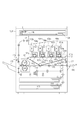
図1は、本発明の実施形態の画像形成装置の断面図である。イエロー、マゼンダ、シアン、ブラックのプロセスユニット101y〜101k(複数の画像形成ユニット)は、感光ドラム(感光体)や現像器、帯電ローラなどを有する。プロセスユニット101k内の感光ドラム102kはモータによって回転駆動される。帯電ローラ103kは、高電圧を感光ドラム102kに印加して感光ドラムの表面を一様に帯電する。レーザスキャナユニット104kは、画像データに応じたレーザ光を射出し、そのレーザ光は、回転駆動されるポリゴンミラーにより反射されて、感光ドラム102k上で露光走査され、感光ドラム上には静電潜像が形成される。現像器105kは、感光ドラムに形成された静電潜像をトナーにより現像する。トナーが充填されたトナーボトル106kは、現像器105kにトナーを供給する。一次転写ローラ107kは、感光ドラム上のトナー像を無端ベルト状部材である中間転写体108(像担持体)に一次転写し、中間転写体108上にY、M、C、K各色のトナー像を重ね合わせる。補助帯電ブラシ109kは、中間転写体108上に転写されずに感光ドラム上に残ったトナーを帯電させる。
FIG. 1 is a cross-sectional view of an image forming apparatus according to an embodiment of the present invention. The yellow, magenta, cyan, and
ここまで、ブラックのプロセスユニット101k(感光ドラム102k、帯電ローラ103k、現像器105k、補助帯電ブラシ109k)に関してのみ説明したが、イエロー、マゼンダ、シアンのプロセスユニットも同様である。以下、感光ドラム102、帯電ローラ103、現像器105、補助帯電ブラシ109と記述した場合、イエロー、マゼンダ、シアン、ブラックの各色を含むものとする。中間転写体108に一次転写されたトナー像は、二次転写ローラ110によって用紙上に二次転写される。用紙に転写されずに中間転写体108上に残ったトナーや、用紙上に転写することを意図しない調整用のトナー像は、クリーナ111によって回収される。パターン検知センサ112は、中間転写体108上に作像されたトナーパターン画像のエッジを検出する。
Up to this point, only the
用紙は、用紙カセット113に収納されており、給紙ローラ114によって搬送され、レジストローラ115によって斜行を補正された後、二次転写ローラ110に送られる。用紙は、二次転写ローラ110でトナー像を転写された後、定着ローラ117および加圧ローラ118によってトナーが熱定着され、排紙フラッパ119によって排紙トレイ120もしくはインナー排紙トレイ121に送られる。
The paper is stored in a
画像形成装置の外装部には、中間転写体108を装置に対して脱着するためのドアが設けられており、ドアの開閉状態を検知するための転写ユニットドア開閉検知センサ122が設けられている。転写ユニットドア開閉検知センサ122は発光ダイオードとフォトダイオードによって構成される。中間転写体108が脱着可能なドア開状態では、発光ダイオードの光がフォトダイオードに受光され、画像形成を行うドア閉状態では、発光ダイオードの光は遮光されてフォトダイオードには受光されない。転写ユニットドア開閉検知センサ122はドアの開閉に応じた信号を出力する。
The exterior of the image forming apparatus is provided with a door for detaching the
図2は、画像形成装置の制御ブロック構成図である。CPU201は、画像形成装置の制御を行う。ROM202は、CPU201が動作するためのプログラムを格納している。RAM203は、CPU201が一時的にデータを記憶しておくために使用される。バックアップRAM204は、画像形成装置で設定された情報を、電源を切断しても記録しておくことを可能にするためのもので、バックアップバッテリによって電源供給されている。入出力ポート205は、CPU201に接続されるデバイスとのインターフェイスである。
FIG. 2 is a control block configuration diagram of the image forming apparatus. The
コントローラI/F206は、入力画像信号を供給するプリンタコントローラと接続するためのインターフェイスである。レーザドライバ207は、レーザスキャナユニット104y〜104kを駆動制御する。モータドライバ208は、感光ドラム102、中間転写体108、給紙ローラ114、及びレジストローラ115を回転駆動するモータを制御する。高圧制御ユニット209は、プロセスユニット101の帯電ローラ103、現像器105、一次転写ローラ107、及び二次転写ローラ110の高電圧出力を制御する。前述のパターン検知センサ112はI/O205を介してCPU201に接続されている。センサ類211は、用紙の有無や搬送位置、電位や温度などを検出する。前述の転写ユニットドア開閉検知センサ122はI/O205を介してCPU201に接続されている。CPU201は100ミリ秒間隔で転写ユニットドア開閉検知センサ122を監視しており、ドア開が行われると、バックアップRAM204にドア開閉検知履歴を記録する。EEPROM213は、レーザスキャナユニット104に備えられ、レーザスキャナユニット104の持つ固有の補正値を記憶している。
A controller I / F 206 is an interface for connecting to a printer controller that supplies an input image signal. The
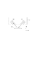
図3は、パターン検知センサ112の構成を説明する図である。パターン検知センサ112は、赤外線LED等によって構成された発光部301と、フォトトランジスタ等によって構成された受光部303を有する。発光部301は中間転写体108の表面に対して斜めに発光する位置及び向きに設けられ、受光部303は中間転写体108からの正反射光を受光する位置及び向きに設けられている。発光部301が発光した赤外光は中間転写体108によって反射され、その正反射光が受光部303に入射する。受光部303が受光した反射光量の変化によって、中間転写体108上の色ずれ検知パターン302を検出する。受光部303によって受光された反射光は、反射光量に応じた電気信号に変換される。
FIG. 3 is a diagram illustrating the configuration of the
受光部303から出力される電気信号は、反射光量が少ないほど電圧が低く、反射光量が多いほど電圧が高い。中間転写体108上に載っているトナー量が多いほど反射光量は少なく、少ないほど反射光量は多い。また、中間転写体108の表面は光沢があるため、中間転写体108上にトナーがないとき、中間転写体108上にトナーがあるときに比べて、反射光量が多い。そこで、パターン検知センサ112の出力電圧が所定値以上のとき色ずれ検知パターン302がない、所定値未満のとき色ずれ検知パターン302があると判断する。
The electrical signal output from the
図4は、中間転写体108上に形成された色ずれ検知パターン302を示す図である。パターン検知センサ112と、中間転写体108と、色ずれ検知パターン302との位置関係は図4のようになっている。パターン検知センサ112は、移動する中間転写体108上に形成された複数の色ずれ検知パターン302を読み取る。
FIG. 4 is a diagram showing a color
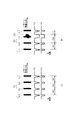
図5は、色ずれ検知パターンを用いた色ずれ量検知を説明する図である。図5(a)のパターン501はイエロー、パターン502はマゼンダ、パターン503はシアン、パターン504はブラックのトナーで作像されたパターンであり、それぞれ300画素間隔で形成される。これらのパターンは、中間転写体108上に形成された後、パターン検知センサ112によって検知される。パターン検知センサ112の受光部303の出力電圧505は、コンパレータによって閾値電圧と比較され、エッジ検出波形506が得られる。コンパレータは、受光部303の出力電圧505が閾値以上のときハイレベルを、閾値未満のときローレベルを出力する。
FIG. 5 is a diagram for explaining color misregistration detection using a color misregistration detection pattern. In FIG. 5A, the
CPU201は、内蔵クロックによってカウントするタイマカウンタによって、I/O205を介して入力されたエッジ検出波形506の立ち下がりエッジから次の立ち下がりエッジまでの時間を計時する。図5(a)において、時間(カウント値)507はイエローとマゼンダの間の距離、時間(カウント値)508はマゼンダとシアンの間の距離、時間(カウント値)509はシアンとブラックの間の距離を示す。パターン501〜504はそれぞれ300画素間隔で形成するので、タイマカウント値を画素数に換算し、この画素数から300画素を減じた結果が色ずれ量を表す。この色ずれ量は、複数の画像形成ユニットにより形成される画像の像担持体上での位置ずれ量である。CPU201は、色ずれと相反する方向に色ずれ量に応じた分、画像の書出しタイミングをずらすことによって、色ずれの補正を行う。
The
図5(b)は、中間転写体108上にキズがある場合の色ずれ検知を説明する図である。図5(b)のパターン511はイエロー、パターン512はマゼンダ、パターン513はシアン、パターン514はブラックのトナーで作像されたパターンであり、それぞれ300画素間隔で形成される。図5(b)は、マゼンダのパターン512が中間転写体108のキズ520の上に形成されてしまった例を示す。
FIG. 5B is a diagram for explaining color misregistration detection when there is a scratch on the
このときのパターン検知センサ112は、キズ520をマゼンダのパターン512と誤検知してしまう。受光部303の出力電圧515は、マゼンダのパターン512がパターン検知センサ112に到達する前にキズ520による反射光量の低下によって電圧低下してしまう。従って、コンパレータの出力するエッジ検出波形516の立ち下がりエッジが、マゼンダのパターン512に相当する立下りエッジだけが本来よりも早まってしまう。その結果、シアンとブラックの間の距離を示す時間(カウント値)519は実際の距離を示しているが、イエローとマゼンダの間の距離を示す時間(カウント値)517とマゼンダとシアンの間の距離を示す時間(カウント値)518は実際と異なる距離を示してしまう。この場合、色ずれ検知結果に応じた補正を行うと、却って色ずれが悪化してしまう。
The
このように、中間転写体108上のキズによって色ずれ検知パターン間の距離が異常に大きく検出される場合がある。このような色ずれ検知パターン間の距離が異常に大きく検出される現象は、中間転写体108の駆動ローラのスリップによって、中間転写体108の移動速度が一瞬だけ減速するような場合にも生じる。そこで、CPU201は、色ずれ検知パターン間の距離が異常に大きい、つまり、色ずれ検知パターン間の距離が色ずれ補正許容量を超える場合には、色ずれ検知結果を無視して、色ずれ補正を行わないようにする。
As described above, the distance between the color misregistration detection patterns may be detected to be abnormally large due to the scratch on the
但し、どのような状況においても常に同じ色ずれ補正許容量を用いると、誤検知ではなく実際に大きな色ずれが生じている場合に色ずれ補正をすることができない。例えば、画像形成装置内のユニット交換によってユニットの位置が変動するような場合に、大きな量の色ずれが発生しうるからである。そこで、本実施形態では、色ずれ補正を開始する条件であるところの色ずれ補正要因に対応した色ずれ補正許容量を用いる。 However, if the same color misregistration correction allowance is always used in any situation, color misregistration correction cannot be performed when a large color misregistration actually occurs rather than erroneous detection. This is because, for example, a large amount of color misregistration can occur when the position of the unit varies due to unit replacement in the image forming apparatus. Therefore, in this embodiment, a color misregistration correction allowable amount corresponding to a color misregistration correction factor, which is a condition for starting color misregistration correction, is used.
図6は、色ずれ補正を開始する条件を判断する処理のフローチャートである。図6に示される処理は、電源投入時、ドア開閉時、プリントジョブ開始時・終了時、プリントジョブ中の200枚プリント毎に実行される。まず、CPU201は、色ずれ補正要因情報をクリアし(S102)、レーザスキャナユニット104のEEPROM213を読み取る(S103)。そして、CPU201は、EEPROM213のデータのチェックサムが、バックアップRAM204に記憶してある前回のチェックサムと異なるか判断し(S104)、異なる場合、色ずれ補正要因情報をレーザスキャナユニット交換として、色ずれ補正を開始する(S105)。ステップS104で異ならない場合は、感光ドラム(感光体)を有するドラムカートリッジのメモリタグから固有識別IDを読み取り(S106)、固有識別IDがバックアップRAM204に記憶してある前回と異なるか判断する(S107)。
FIG. 6 is a flowchart of processing for determining a condition for starting color misregistration correction. The processing shown in FIG. 6 is executed every time 200 sheets are printed during power-on, door opening / closing, print job start / end, and print job. First, the
ステップS107で異なる場合、色ずれ補正要因情報をドラムカートリッジ交換として、色ずれ補正を開始する(S108)。ステップS107で異ならない場合、バックアップRAM204に保存された転写ユニット着脱ドア開閉検知履歴を参照する(S109)。ステップS109で開閉検知履歴が保存されている場合、色ずれ補正要因情報を中間転写体ユニット着脱として、色ずれ補正を開始し(S110)、バックアップRAM204に保存されている転写ユニット着脱ドア開閉検知履歴をクリアする。
If they are different in step S107, the color misregistration correction is started by replacing the color misregistration correction factor information with the drum cartridge (S108). If not different in step S107, the transfer unit attachment / detachment door opening / closing detection history stored in the
ステップS109で開閉検知履歴が保存されていない場合、前回色ずれ補正時の温度と現在の温度との差を判断する(S112)。ステップS112で温度差が所定値Lを超えている場合、色ずれ補正要因情報を温度変動大として、色ずれ補正を開始する(S113)。ステップS112で温度差が所定値L以下の場合、前回の色ずれ補正時間からの経過時間が所定時間Mを超えているか判断する(S114)。ステップS114で所定時間M経過している場合、色ずれ補正要因情報を所定時間経過として、色ずれ補正を開始する(S115)。ステップS114で所定時間M経過していない場合、前回の色ずれ補正時のプリント枚数カウンタと現在のプリント枚数カウンタの枚数差が所定枚数(所定頁数)Nを超えているか判断する(S116)。ステップS116で所定枚数Nを超えている場合、色ずれ補正要因情報を所定枚数経過として、色ずれ補正を開始する(S117)。 If the opening / closing detection history is not stored in step S109, the difference between the temperature at the previous color misregistration correction and the current temperature is determined (S112). If the temperature difference exceeds the predetermined value L in step S112, the color misregistration correction is started by setting the color misregistration correction factor information as a large temperature fluctuation (S113). If the temperature difference is equal to or smaller than the predetermined value L in step S112, it is determined whether the elapsed time from the previous color misregistration correction time exceeds the predetermined time M (S114). If the predetermined time M has elapsed in step S114, the color misregistration correction is started with the color misregistration correction factor information as the predetermined time elapse (S115). If the predetermined time M has not elapsed in step S114, it is determined whether or not the difference between the print number counter at the time of the previous color misregistration correction and the current print number counter exceeds a predetermined number (predetermined number of pages) N (S116). When the predetermined number N is exceeded in step S116, the color misregistration correction is started with the color misregistration correction factor information set as the elapse of the predetermined number (S117).
ステップS116で所定枚数Nを超えていない場合、すなわち、いずれの条件にも該当しない場合、色ずれ補正を開始しない。このように、複数の条件のいずれかを満たす場合、色ずれ量の検知及び色ずれの補正を行う処理へ進む。CPU201は、色ずれ補正要因情報をRAM203に格納する。
If the predetermined number N is not exceeded in step S116, that is, if any of the conditions is not met, the color misregistration correction is not started. As described above, when any one of the plurality of conditions is satisfied, the process proceeds to a process of detecting the color misregistration amount and correcting the color misregistration. The
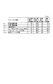
図7は、色ずれ補正要因毎の色ずれ補正許容量を示す図である。図7の色ずれ補正許容量は画素数で示され、色ずれ補正要因別のテーブル情報としてROM202に記憶されている。色ずれ補正要因によって発生しうる色ずれの量は異なる。第1の条件であるところの、所定頁数の画像を形成した場合(701)や、所定時間が経過した場合(702)は、色ずれが発生しうる要因には成り得るが、主走査位置、副走査位置、倍率、傾斜角の色ずれ量は小さい。つまり、所定枚数のプリントを行ったときや、所定時間が経過したときに、大きな色ずれを検出した場合、色ずれ検知パターンの誤検知である可能性が大きい。そのため、色ずれ補正許容量は他の場合に比べて小さくする。
FIG. 7 is a diagram showing a color misregistration correction allowable amount for each color misregistration correction factor. The color misregistration correction allowable amount in FIG. 7 is indicated by the number of pixels, and is stored in the
また、温度変動が大きい場合(703)については、機内の温度が著しく変化する起動から数分間を除いては、大きな色ずれが発生しうる可能性が低い。このため、温度変動が大きいときに、大きな色ずれを検出した場合、色ずれ検知パターンの誤検知である可能性が高いため、色ずれ補正許容量は小さめにする。 In the case where the temperature fluctuation is large (703), it is unlikely that a large color shift may occur except for several minutes after the start-up in which the temperature inside the machine changes significantly. For this reason, when a large color shift is detected when the temperature fluctuation is large, the color shift correction allowable amount is set to be small because there is a high possibility that the color shift detection pattern is erroneously detected.
一方、レーザスキャナユニットを交換したとき(704)、ユニットの枠体やレンズの個体差や、主走査位置、副走査位置、倍率、傾斜角に関して取り付け精度が大きく影響することから、主走査位置、副走査位置、倍率、傾斜角に大きな色ずれが発生しうる可能性が高い。そこで、レーザスキャナユニットを交換したときは、大きな色ずれを検出した場合でも色ずれ補正するために、色ずれ補正許容量は大きめにする。また、ドラムカートリッジを交換したとき(705)も、副走査方向や角度の取り付け精度が大きく影響することから、副走査位置、傾斜角に大きな色ずれが発生しうる可能性が高い。そこで、ドラムカートリッジを交換したときは、大きな色ずれを検出した場合でも色ずれ補正するために、色ずれ補正許容量は大きめにする。 On the other hand, when the laser scanner unit is replaced (704), the mounting accuracy greatly affects the individual difference of the frame and lens of the unit, the main scanning position, the sub-scanning position, the magnification, and the inclination angle. There is a high possibility that a large color shift may occur in the sub-scanning position, magnification, and tilt angle. Therefore, when the laser scanner unit is replaced, the color misregistration correction allowable amount is increased in order to correct the color misregistration even when a large color misregistration is detected. In addition, when the drum cartridge is replaced (705), since the accuracy of the sub-scanning direction and the angle is greatly affected, there is a high possibility that a large color shift may occur in the sub-scanning position and the inclination angle. Therefore, when the drum cartridge is replaced, the color misregistration correction allowable amount is increased in order to correct the color misregistration even when a large color misregistration is detected.
さらに、中間転写体を含む転写ユニットを脱着したとき(706)は、主走査方向の取り付け精度が大きく影響することから、主走査位置に大きな色ずれが発生しうる可能性が高い。そこで転写ユニットを脱着したときは、大きな色ずれを検出した場合でも色ずれ補正するために、色ずれ補正許容量は大きめにする。これらのユニット交換を色ずれ補正要因とする第2の条件に対応する色ずれ補正許容量は、上述の第1の条件に対応する色ずれ補正許容量よりも大きい。 Further, when the transfer unit including the intermediate transfer member is detached (706), the attachment accuracy in the main scanning direction is greatly affected, so that there is a high possibility that a large color shift may occur at the main scanning position. Therefore, when the transfer unit is detached, the color misregistration correction allowable amount is increased in order to correct the color misregistration even when a large color misregistration is detected. The color misregistration correction allowable amount corresponding to the second condition where the unit replacement is a color misregistration correction factor is larger than the color misregistration correction allowable amount corresponding to the first condition described above.
図8は、色ずれ補正許容量を用いた色ずれ補正処理のフローチャートである。まず、CPU201は、図6のフローで判定した色ずれ補正要因情報をRAM203から読み出し、ROM202に記憶された図7のテーブル情報を参照して、色ずれ補正要因情報に対応する色ずれ補正許容量を決定する(S202)。次に、CPU201は、中間転写体108上に色ずれ補正パターンを形成させ(S203)、パターン検知センサ112を用いて色ずれパターン検出を行う(S204)。そして、色ずれパターン検出結果から求めた色ずれ検知量が色ずれ補正許容量を超えているか判別し(S205)、色ずれ補正許容量を超えている場合には、再び中間転写体108上に色ずれ補正パターンを形成させ(S206)、パターン検知センサ112を用いて色ずれパターン検出を行う(S207)。そして、色ずれパターン検出結果から求めた色ずれ検知量が色ずれ補正許容量を超えているか判別する(S208)。
FIG. 8 is a flowchart of color misregistration correction processing using the color misregistration correction allowable amount. First, the
ステップS205またはS208で色ずれ検知量が色ずれ補正許容量以下であった場合は、色ずれ検知量をバックアップRAM204上に色ずれ補正値として保存し(S209)、色ずれ補正値を用いた色ずれ補正を行う(色ずれ補正値を画像形成にフィードバックする)(S210)。ステップS208で色ずれ検知量が色ずれ補正許容量を超えている場合は、色ずれ検知パターンの誤検知である可能性が高いため、色ずれ検知量を用いた色ずれ補正を行なわずに処理を終了する。なお、色ずれ検知量を用いた色ずれ補正は、色ずれ補正値に応じて画像書き出しタイミングを補正することで主走査及び副走査の色ずれ補正を行い、色ずれ補正値に応じて画像処理により画像の変倍及び回転を行うことで倍率及び傾きの色ずれ補正を行う。
If the color misregistration detection amount is equal to or less than the color misregistration correction allowable amount in step S205 or S208, the color misregistration detection amount is stored in the
以上のように、複数の条件によって異なる色ずれ補正許容量以下の、色ずれ検知パターンを用いて検知された色ずれ量に応じて複数の画像形成ユニットにより形成される画像の位置ずれを補正する。また、色ずれ検知パターンを用いて検知された色ずれ量が条件に対応した位置ずれ補正許容量を超える場合、色ずれ検知パターンを用いて検知された色ずれ量は用いない。このように、色ずれ補正要因に応じて色ずれ補正許容量を決定することで、中間転写体(像担持体)の傷や中間転写体の速度変動などによる誤検知及び誤補正を低減でき、ユニットの交換によって起こりえる色ずれを効果的に補正することが可能となる。 As described above, the misregistration of images formed by a plurality of image forming units is corrected in accordance with the color misregistration amount detected using the color misregistration detection pattern that is equal to or less than the color misregistration correction allowable amount that varies depending on a plurality of conditions. . In addition, when the color misregistration amount detected using the color misregistration detection pattern exceeds the misregistration correction allowable amount corresponding to the condition, the color misregistration amount detected using the color misregistration detection pattern is not used. In this way, by determining the color misregistration correction allowable amount according to the color misregistration correction factor, it is possible to reduce erroneous detection and correction due to scratches on the intermediate transfer body (image carrier) or speed fluctuations of the intermediate transfer body, It is possible to effectively correct color misregistration that may occur due to unit replacement.
なお、上述の実施形態では、中間転写体を介して感光ドラム上の画像を用紙に転写したが、感光ドラム上の画像を用紙(像担持体)に直接転写する画像形成装置でもよい。 In the above-described embodiment, the image on the photosensitive drum is transferred to the paper via the intermediate transfer member. However, an image forming apparatus that directly transfers the image on the photosensitive drum to the paper (image carrier) may be used.
101 プロセスユニット(画像形成ユニット)
108 中間転写体(像担持体)
112 パターン検知センサ
101 process unit (image forming unit)
108 Intermediate transfer member (image carrier)
112 Pattern detection sensor
Claims (8)
複数の条件のいずれかを満たす場合、前記複数の画像形成手段により形成される画像の前記像担持体上での位置ずれ量を検知する検知手段と、
前記複数の条件によって異なる位置ずれ補正許容量以下の、前記検知手段により検知された前記位置ずれ量に応じて前記複数の画像形成手段により形成される画像の位置ずれを補正する補正手段と、
を有することを特徴とする画像形成装置。 A plurality of image forming means for superimposing and forming an image on the image carrier;
When satisfying any one of a plurality of conditions, a detection unit that detects a displacement amount of an image formed by the plurality of image forming units on the image carrier;
A correction unit that corrects a positional deviation of an image formed by the plurality of image forming units according to the positional deviation amount detected by the detection unit, which is equal to or less than a positional deviation correction allowable amount that varies depending on the plurality of conditions;
An image forming apparatus comprising:
前記複数の条件に含まれる第2の条件は、前記感光体が交換されたことであり、
前記第2の条件に対応する前記位置ずれ補正許容量は、前記第1の条件に対応する前記位置ずれ補正許容量よりも大きいことを特徴とする請求項5記載の画像形成装置。 Each of the plurality of image forming units has a photoconductor,
The second condition included in the plurality of conditions is that the photoconductor is replaced,
The image forming apparatus according to claim 5, wherein the misalignment correction allowance corresponding to the second condition is larger than the misalignment correction allowance corresponding to the first condition.
前記第2の条件に対応する前記位置ずれ補正許容量は、前記第1の条件に対応する前記位置ずれ補正許容量よりも大きいことを特徴とする請求項5記載の画像形成装置。 The second condition included in the plurality of conditions is that the image carrier is replaced,
The image forming apparatus according to claim 5, wherein the misalignment correction allowance corresponding to the second condition is larger than the misalignment correction allowance corresponding to the first condition.
前記複数の条件に含まれる第2の条件は、前記露光手段が交換されたことであり、
前記第2の条件に対応する前記位置ずれ補正許容量は、前記第1の条件に対応する前記位置ずれ補正許容量よりも大きいことを特徴とする請求項5記載の画像形成装置。 Exposure means for performing exposure scanning according to image data on the photoreceptors respectively included in the plurality of image forming means;
The second condition included in the plurality of conditions is that the exposure means has been replaced,
The image forming apparatus according to claim 5, wherein the misalignment correction allowance corresponding to the second condition is larger than the misalignment correction allowance corresponding to the first condition.
Priority Applications (2)
| Application Number | Priority Date | Filing Date | Title |
|---|---|---|---|
| JP2010286522A JP2012133216A (en) | 2010-12-22 | 2010-12-22 | Image formation device |
| US13/327,629 US8837994B2 (en) | 2010-12-22 | 2011-12-15 | Method for controlling image forming apparatus, and image forming apparatus |
Applications Claiming Priority (1)
| Application Number | Priority Date | Filing Date | Title |
|---|---|---|---|
| JP2010286522A JP2012133216A (en) | 2010-12-22 | 2010-12-22 | Image formation device |
Publications (2)
| Publication Number | Publication Date |
|---|---|
| JP2012133216A true JP2012133216A (en) | 2012-07-12 |
| JP2012133216A5 JP2012133216A5 (en) | 2014-02-13 |
Family
ID=46316983
Family Applications (1)
| Application Number | Title | Priority Date | Filing Date |
|---|---|---|---|
| JP2010286522A Pending JP2012133216A (en) | 2010-12-22 | 2010-12-22 | Image formation device |
Country Status (2)
| Country | Link |
|---|---|
| US (1) | US8837994B2 (en) |
| JP (1) | JP2012133216A (en) |
Cited By (5)
| Publication number | Priority date | Publication date | Assignee | Title |
|---|---|---|---|---|
| JP2014215535A (en) * | 2013-04-26 | 2014-11-17 | 株式会社沖データ | Image formation device and method for controlling image formation device |
| US9261807B2 (en) | 2014-02-25 | 2016-02-16 | Canon Kabushiki Kaisha | Image forming apparatus that forms color image by superimposing plurality of images in different colors |
| US9361551B2 (en) | 2014-02-25 | 2016-06-07 | Canon Kabushiki Kaisha | Image forming apparatus that forms color image by superimposing plurality of images |
| JP2016139117A (en) * | 2015-01-21 | 2016-08-04 | キヤノン株式会社 | Image forming apparatus |
| US10061249B2 (en) | 2014-02-25 | 2018-08-28 | Canon Kabushiki Kaisha | Image forming apparatus that forms color image by superimposing plurality of images in different colors |
Families Citing this family (8)
| Publication number | Priority date | Publication date | Assignee | Title |
|---|---|---|---|---|
| SG192296A1 (en) * | 2012-01-09 | 2013-08-30 | Venture Corp Ltd | An apparatus and methods for dispensing at least one segment of a printed media sheet with a plurality of segments |
| JP2013225085A (en) * | 2012-03-19 | 2013-10-31 | Ricoh Co Ltd | Image forming apparatus |
| JP6504801B2 (en) * | 2014-11-28 | 2019-04-24 | キヤノン株式会社 | Image forming device |
| US9477193B2 (en) * | 2015-01-21 | 2016-10-25 | Canon Kabushiki Kaisha | Image forming apparatus |
| JP2018004799A (en) | 2016-06-29 | 2018-01-11 | キヤノン株式会社 | Image formation device |
| JP6836305B2 (en) * | 2017-01-13 | 2021-02-24 | キヤノン株式会社 | Imaging control device and its control method |
| US10444693B2 (en) * | 2017-11-02 | 2019-10-15 | Canon Kabushiki Kaisha | Image forming apparatus |
| US11592774B2 (en) * | 2020-12-14 | 2023-02-28 | Ricoh Company, Ltd. | Image forming apparatus and image forming method |
Citations (3)
| Publication number | Priority date | Publication date | Assignee | Title |
|---|---|---|---|---|
| JPS63286865A (en) * | 1987-05-19 | 1988-11-24 | Ricoh Co Ltd | Image forming device |
| JP2004069908A (en) * | 2002-08-05 | 2004-03-04 | Canon Inc | Color slippage correcting device for color image forming apparatus |
| JP2005316118A (en) * | 2004-04-28 | 2005-11-10 | Fuji Xerox Co Ltd | Color image forming apparatus provided with position-shifting correction mode |
Family Cites Families (8)
| Publication number | Priority date | Publication date | Assignee | Title |
|---|---|---|---|---|
| JP3273810B2 (en) * | 1992-07-30 | 2002-04-15 | キヤノン株式会社 | Image forming device |
| US5828925A (en) * | 1995-03-31 | 1998-10-27 | Canon Kabushiki Kaisha | Image forming apparatus capable of correcting position deviation of image |
| JP2003098795A (en) * | 2001-09-26 | 2003-04-04 | Canon Inc | Image forming apparatus |
| JP2003122082A (en) * | 2001-10-09 | 2003-04-25 | Canon Inc | Image forming apparatus |
| JP2005092131A (en) * | 2003-09-19 | 2005-04-07 | Ricoh Co Ltd | Image forming apparatus |
| JP4963390B2 (en) * | 2006-09-19 | 2012-06-27 | 株式会社リコー | Misalignment correction apparatus and color image forming apparatus |
| JP4784628B2 (en) * | 2008-09-25 | 2011-10-05 | ブラザー工業株式会社 | Image forming apparatus |
| JP2011046492A (en) * | 2009-08-27 | 2011-03-10 | Canon Inc | Sheet carrying device and image forming device |
-
2010
- 2010-12-22 JP JP2010286522A patent/JP2012133216A/en active Pending
-
2011
- 2011-12-15 US US13/327,629 patent/US8837994B2/en not_active Expired - Fee Related
Patent Citations (3)
| Publication number | Priority date | Publication date | Assignee | Title |
|---|---|---|---|---|
| JPS63286865A (en) * | 1987-05-19 | 1988-11-24 | Ricoh Co Ltd | Image forming device |
| JP2004069908A (en) * | 2002-08-05 | 2004-03-04 | Canon Inc | Color slippage correcting device for color image forming apparatus |
| JP2005316118A (en) * | 2004-04-28 | 2005-11-10 | Fuji Xerox Co Ltd | Color image forming apparatus provided with position-shifting correction mode |
Cited By (6)
| Publication number | Priority date | Publication date | Assignee | Title |
|---|---|---|---|---|
| JP2014215535A (en) * | 2013-04-26 | 2014-11-17 | 株式会社沖データ | Image formation device and method for controlling image formation device |
| US9261807B2 (en) | 2014-02-25 | 2016-02-16 | Canon Kabushiki Kaisha | Image forming apparatus that forms color image by superimposing plurality of images in different colors |
| US9361551B2 (en) | 2014-02-25 | 2016-06-07 | Canon Kabushiki Kaisha | Image forming apparatus that forms color image by superimposing plurality of images |
| US9366984B2 (en) | 2014-02-25 | 2016-06-14 | Canon Kabushiki Kaisha | Image forming apparatus that forms color image by superimposing plurality of images in different colors |
| US10061249B2 (en) | 2014-02-25 | 2018-08-28 | Canon Kabushiki Kaisha | Image forming apparatus that forms color image by superimposing plurality of images in different colors |
| JP2016139117A (en) * | 2015-01-21 | 2016-08-04 | キヤノン株式会社 | Image forming apparatus |
Also Published As
| Publication number | Publication date |
|---|---|
| US8837994B2 (en) | 2014-09-16 |
| US20120163880A1 (en) | 2012-06-28 |
Similar Documents
| Publication | Publication Date | Title |
|---|---|---|
| JP2012133216A (en) | Image formation device | |
| JP5764878B2 (en) | Image forming apparatus, correction control method, and correction control program | |
| US7817947B2 (en) | Image forming apparatus and correction method of color-misregistration in an image | |
| US9128439B2 (en) | Image forming apparatus and conveyance control method | |
| JP5258850B2 (en) | Image forming apparatus | |
| JP2008032960A (en) | Image forming device | |
| US8630560B2 (en) | Printing apparatus | |
| US8761622B2 (en) | Image forming apparatus and method for controlling image forming apparatus | |
| US10915994B2 (en) | Image forming apparatus | |
| US7773897B2 (en) | Image forming apparatus and control method thereof | |
| US9235179B2 (en) | Image forming apparatus for forming, detecting, and correcting sandwiched toner pattern | |
| JP4343149B2 (en) | Image forming apparatus and color misregistration correction method | |
| JP5731769B2 (en) | Image forming apparatus and control method thereof | |
| US8540334B2 (en) | Image forming apparatus and method | |
| JP2008209659A (en) | Image forming device and control method | |
| US10061249B2 (en) | Image forming apparatus that forms color image by superimposing plurality of images in different colors | |
| JP6127478B2 (en) | Image forming apparatus and conveyance control method | |
| JP7067315B2 (en) | Image forming device | |
| US11513461B2 (en) | Image forming apparatus and image quality adjustment method | |
| JP2009169002A (en) | Image forming apparatus | |
| JP2017161559A (en) | Image forming apparatus, image density adjustment method, and program | |
| JP2014109730A (en) | Image forming apparatus and conveyance control method | |
| US20160255226A1 (en) | Image forming apparatus | |
| JP2005089018A (en) | Method and device for sensing number of paper sheets, paper feeding device, and image forming device with it | |
| JP2006276394A (en) | Multicolor image forming apparatus |
Legal Events
| Date | Code | Title | Description |
|---|---|---|---|
| A521 | Written amendment |
Free format text: JAPANESE INTERMEDIATE CODE: A523 Effective date: 20131224 |
|
| A621 | Written request for application examination |
Free format text: JAPANESE INTERMEDIATE CODE: A621 Effective date: 20131224 |
|
| A131 | Notification of reasons for refusal |
Free format text: JAPANESE INTERMEDIATE CODE: A131 Effective date: 20140924 |
|
| A977 | Report on retrieval |
Free format text: JAPANESE INTERMEDIATE CODE: A971007 Effective date: 20140924 |
|
| A521 | Written amendment |
Free format text: JAPANESE INTERMEDIATE CODE: A523 Effective date: 20141125 |
|
| A02 | Decision of refusal |
Free format text: JAPANESE INTERMEDIATE CODE: A02 Effective date: 20150519 |
|
| A521 | Written amendment |
Free format text: JAPANESE INTERMEDIATE CODE: A523 Effective date: 20160714 |