EP3348949B1 - Längenverstellbarer gewehranschlag - Google Patents
Längenverstellbarer gewehranschlag Download PDFInfo
- Publication number
- EP3348949B1 EP3348949B1 EP17210902.7A EP17210902A EP3348949B1 EP 3348949 B1 EP3348949 B1 EP 3348949B1 EP 17210902 A EP17210902 A EP 17210902A EP 3348949 B1 EP3348949 B1 EP 3348949B1
- Authority
- EP
- European Patent Office
- Prior art keywords
- butt plate
- butt
- locking
- plate shaft
- pad assembly
- Prior art date
- Legal status (The legal status is an assumption and is not a legal conclusion. Google has not performed a legal analysis and makes no representation as to the accuracy of the status listed.)
- Active
Links
Images


Classifications
-
- F—MECHANICAL ENGINEERING; LIGHTING; HEATING; WEAPONS; BLASTING
- F41—WEAPONS
- F41C—SMALLARMS, e.g. PISTOLS, RIFLES; ACCESSORIES THEREFOR
- F41C23/00—Butts; Butt plates; Stocks
- F41C23/14—Adjustable stock or stock parts, i.e. adaptable to personal requirements, e.g. length, pitch, cast or drop
-
- F—MECHANICAL ENGINEERING; LIGHTING; HEATING; WEAPONS; BLASTING
- F41—WEAPONS
- F41C—SMALLARMS, e.g. PISTOLS, RIFLES; ACCESSORIES THEREFOR
- F41C23/00—Butts; Butt plates; Stocks
- F41C23/04—Folding or telescopic stocks or stock parts
Definitions
- the disclosure relates to firearms and more particularly to features of a length adjustable firearm butt pad assembly.
- Firearm stocks are typically fixed in a single position, and the end of the stock (normally a butt pad) is designed to fit into a user's shoulder pocket. Because the stock is fixed, the user must acclimate to the position of the stock. However, there can be significant variation in the shape and size of a user's shoulder. Such variation can result in discomfort, inaccurate, and unsafe shooting positions. Moreover, a user's clothing and load out can significantly vary from one situation to another. Although available contemporary stock assemblies provide for adjusting an aspect of the stock, making the adjustment normally requires manipulating one or more unlocking one or more elements, and cannot be done without a special tool or under duress. As a result, the stock position cannot be easily adjusted under duress.
- US8186090 discloses a complete buttstock for a weapon including a buttplate.
- the buttplate is mounted to an outer stock, and an inner stock is slide into said outer stock.
- Spring biased upper and lower engagement pins are arranged as a locking mechanism in the inner stock and extend into holes in the outer stock.
- the inner stock is fixed to a backplate that engages with a receiver of the weapon.
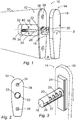
- an adjustable butt pad assembly 10 for a firearm in accordance with the invention shown in Fig. 1 comprises a butt plate base 12 and a butt plate 14.
- Butt plate 14 comprises a butt plate shaft 16 fitting inside a mounting tube 18 of butt plate base 12, and a butt plate rear part 19.
- Butt plate shaft 16 can be adjusted in a longitudinal direction of mounting tube 18, so as to displace butt plate 14 into different horizontal locations as indicated at arrow A. Different horizontal locations are determined by a plurality of locking notches 20 formed in the butt plate shaft 16 and at least one internal and radially extending locking lug 22 in mounting tube 18.
- Butt plate shaft 16 and mounting tube 18 extend along a common axis as depicted by X .
- Common axis X corresponds to the horizontal direction.
- Butt plate 14 can be rotated as depicted by arrow Y around common axis X between a first locked position as shown in Fig. 1 and a second released position in which displacement of butt plate shaft 16 in the direction of common axis X is possible. Rotation of butt plate 14 is possible after releasing a locking mechanism.
- locking mechanism comprises a spring biased locking lever 24.
- the locking mechanism normally is in a secured position as shown in Fig. 1 preventing rotation of butt plate 14. In the secured position, a head 28 of spring biased locking lever 24, c.f. Fig. 6 , is forced into engagement in an axially extending groove 26 formed in butt plate shaft 16.
- the locking mechanism is released by pressing a knob 38 against a spring resulting in a rotating movement around a pin 40.
- the spring biased locking lever 24 is rotated around pin 40 head 28 will moved out of axially extending groove 26 and a rotating movement of butt plate shaft 16 is allowed.
- Butt plate base 12 is selectively attached to a stock 30 of a firearm, such as a rifle.
- mounting tube 18 is inserted into a cavity 32 in the stock 30.
- butt plate 12 is secured in position by screws (not shown) through holes 34 in a plate 36 engaging an end section of the stock 30.
- Plate 36 extends substantially perpendicular to the mounting tube 18.
- FIG. 2 shows an embodiment with four locking notches 20.
- butt plate 14 In the embodiment of butt plate 14 shown in Fig. 3 there are provided two axially extending grooves 26 in diagonally opposite directions in butt plate shaft 16. One of said axially extending grooves 26 will interact with spring biased locking lever 24.
- a stop pin 27 extends radially from butt plate shaft 16 and will prevent a complete withdrawal of butt plate shaft 16 from mounting tube 18. Stop pin 27 extends into axially extending groove 26.
- Butt plate 14 comprises a shaft support plate 21.
- Butt plate shaft 16 extends perpendicularly from shaft support plate 21.
- butt plate rear part 19 can be vertically adjusted to shaft support plate 21, c.f. Fig. 5 below.
- butt plate 14 engages plate 36 and is rotated to a released position. In the rotated and released position it is possible to withdraw butt plate 14 in the direction of arrow W corresponding to axial direction X .
- the butt plate 14 is rotated in the direction of arrow Y until head 28 of spring biased locking lever 24 is pressed down into axially extending groove (not shown in Fig. 4 ).
- head 28 of spring biased locking lever 24 will prevent further rotation of butt plate 14.
- lug 22 received in a locking notch 20 will prevent any axial displacement of butt plate 14 and butt plate shaft 16.
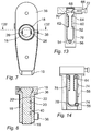
- Fig. 5 and Fig. 6 the butt plate shaft 16 is in locked position and the butt plate 14 is engaging the plate 36.
- butt plate rear part 19 can be vertically displace in relation to butt plate shaft 16.
- Mounting tube 18 extends perpendicularly from plate 36 with butt plate shaft 16 extending concentrically within mounting tube 18.
- Spring based locking lever 24 remains in a locked position until knob 38 is depressed because of the force produced by spring 42.
- knob 38 is depressed, spring biased locking lever 24 rotates around pin 40 as indicated by arrow R and head 28 of spring based locking lever 24 is moved out of axially extending groove 26. All locking notches 20 in butt plate shaft 16 are open in the shown position of butt plate shaft 16.
- Fig. 7 and Fig. 8 show butt pad assembly 10 with plate 36, butt plate rear part 19 and knob 38. As indicated in Fig. 7 butt plate rear part 19 is somewhat axially displaced in relation to plate 36. In Fig. 8 one internal and radially extending locking lug 22 is shown received in a first locking notch 20'. Locking lug 22 will be received in another locking notch 20 after releasing and axially displacing butt plate shaft 16 in mounting tube 18. In various embodiments, two axially extending grooves 26 are formed diagonally opposite to each other in butt plate shaft 16. Butt plate shaft 16 extends in axial alignment with mounting tube 18.
- the first alternative embodiment of a locking mechanism shown in Fig. 9 comprises a sliding body 44 that is spring biased by biasing spring 46 to a locked position shown in dash-and-dot lines. In the locked position sliding body 44 is received in axially extending groove 26 in butt plate shaft 16. Release of the locking mechanism is achieved by sliding said sliding body 44 to the position shown in Fig. 9 in which butt plate shaft 16 can be rotated.
- the second alternative embodiment of a locking mechanism shown in Fig. 10 comprises a rotating body 48 biased to the position shown in dash-and-dot lines.
- Rotating body 48 is formed with a peripheral bevel 50.
- a peripheral section of rotating body 48 is received in axially extending groove 26 in butt plate shaft 16.
- Release of the locking mechanism is achieved by rotating said rotating body 48 to the position shown in Fig. 10 in which said bevel is facing axially extending groove 26 and butt plate shaft 16 can be rotated.
- Fig. 11 shows butt plate shaft 16 in locked position with internal and radially extending locking lugs 22 in engagement with locking notches 20. Some part of locking lugs 22 are received in axially extending grooves 26. In the position of butt plate shaft 16 shown in Fig. 11 no axial movement in mounting tube 18 is possible. After rotation in direction D to a position as shown in Fig. 12 internal and radially extending locking lugs 22 are no longer in engagement with locking notches 20. Instead they are received in axially extending grooves 26. In this position, butt plate shaft 16 is axially displacable.
Landscapes
- Engineering & Computer Science (AREA)
- General Engineering & Computer Science (AREA)
- Toys (AREA)
- Aiming, Guidance, Guns With A Light Source, Armor, Camouflage, And Targets (AREA)
- Chairs For Special Purposes, Such As Reclining Chairs (AREA)
- Chair Legs, Seat Parts, And Backrests (AREA)
Claims (6)
- Längenverstellbare Schaftpolsteranordnung (10) für eine Feuerwaffe, wobei die längenverstellbare Schaftpolsteranordnung (10) Folgendes umfasst:eine Schaftkappe (14), die eine längliche Schaftkappenzahnstange (16; 76) aufweist, wobei die Schaftkappenzahnstange (16; 76) mehrere axial versetzte und sich peripher erstreckende Verriegelungskerben (20) und eine sich axial erstreckende Nut (26) umfasst,einen Schaftkappenträger (12), der ein längliches Befestigungsrohr (18; 58) umfasst, das sich in horizontaler Richtung erstreckt und die Schaftkappenzahnstange (16; 76) aufnimmt,wobei das längliche Befestigungsrohr (18; 58) wenigstens eine innere und sich radial erstreckende Verriegelungsnase (22) umfasst, die konfiguriert ist, um in einer der Verriegelungskerben (20) aufgenommen zu werden,wobei die axial versetzten und sich peripher erstreckenden Verriegelungskerben (20) zu der sich axial erstreckenden Nut (26) offen sind,wobei die Schaftkappenzahnstange (16) und das Befestigungsrohr (18) sich entlang einer gemeinsamen Achse X erstrecken,wobei der Schaftkappenträger (12) einen Verriegelungshebel (24), einen Drehkörper (44) oder einen Gleitkörper (48) umfasst, wobei die Nase (22) und die Nut (26) und die Kerben (20) einen Verriegelungsmechanismus mit einer gesicherten Position, wobei der Verriegelungshebel (24), der Drehkörper (48) oder der Gleitkörper (44) in der sich axial erstreckenden Nut (26) aufgenommen werden, wobei dadurch eine Drehung der Schaftkappe (14) verhindert wird, wobei die Verriegelungsnase (22) in einer Verriegelungskerbe (20) aufgenommen wird und jegliche axiale Versetzung der Schaftkappe (14) und der Schaftkappenzahnstange (16) verhindert, und mit einer Freigabeposition ausbilden, wobei eine Drehung um und eine Verschiebung entlang der Achse X der Schaftkappenzahnstange (16) in dem Befestigungsrohr (18) ermöglicht wird.
- Schaftpolsteranordnung (10) nach Anspruch 1, wobei die Schaftkappenzahnstange (16) wenigstens drei axial versetzte und sich peripher erstreckende Verriegelungskerben (20) umfasst.
- Schaftpolsteranordnung (10) nach Anspruch 1, wobei die wenigstens eine innere und sich radial erstreckende Verriegelungsnase (22) konfiguriert ist, um in der sich axial erstreckenden Nut (26) in der freigegebenen Position aufgenommen zu werden.
- Schaftpolsteranordnung (10) nach Anspruch 1, wobei zwei sich axial erstreckende Nuten (26) in der länglichen Schaftkappenzahnstange (16; 76) an entgegengesetzten Positionen ausgebildet sind und zwei innere und sich radial erstreckende Verriegelungsnasen (22) in dem Befestigungsrohr (18; 58) an entgegengesetzten Positionen bereitgestellt sind, um in die sich axial erstreckenden Nuten (26) in der freigegebenen Position zu passen.
- Schaftpolsteranordnung (10) nach Anspruch 1, wobei der Verriegelungshebel (24) federvorgespannt ist und einen Kopf (28) umfasst, der vorgespannt ist, um in der sich axial erstreckenden Nut (26) aufgenommen zu werden, die in einer länglichen Schaftkappenzahnstange (16; 76) ausgebildet ist.
- Schaftpolsteranordnung (10) nach Anspruch 5, wobei der federvorgespannte Verriegelungshebel (24) um einen Stift (40) drehbar ist, der sich in einer Richtung senkrecht zu der axialen Verschiebungsrichtung der länglichen Schaftkappenzahnstange erstreckt.
Applications Claiming Priority (1)
| Application Number | Priority Date | Filing Date | Title |
|---|---|---|---|
| US15/407,077 US9915498B1 (en) | 2017-01-16 | 2017-01-16 | Length adjustable butt pad assembly |
Publications (2)
| Publication Number | Publication Date |
|---|---|
| EP3348949A1 EP3348949A1 (de) | 2018-07-18 |
| EP3348949B1 true EP3348949B1 (de) | 2020-10-21 |
Family
ID=60813748
Family Applications (1)
| Application Number | Title | Priority Date | Filing Date |
|---|---|---|---|
| EP17210902.7A Active EP3348949B1 (de) | 2017-01-16 | 2017-12-28 | Längenverstellbarer gewehranschlag |
Country Status (3)
| Country | Link |
|---|---|
| US (1) | US9915498B1 (de) |
| EP (1) | EP3348949B1 (de) |
| ES (1) | ES2836708T3 (de) |
Families Citing this family (5)
| Publication number | Priority date | Publication date | Assignee | Title |
|---|---|---|---|---|
| US10161711B2 (en) * | 2016-12-01 | 2018-12-25 | Benelli Armi, S.P.A. | Portable firearm with quick coupling removable stock |
| NO346779B1 (en) * | 2017-12-29 | 2022-12-27 | GRS Riflestocks AS | A modular stock for a firearm |
| ES2755480A1 (es) * | 2018-10-22 | 2020-04-22 | Aguirre Eduardo Ijalba | Amortiguador multirregulable del disparo y arma |
| USD1074908S1 (en) | 2023-04-07 | 2025-05-13 | Colt's Manufacturing Company Llc | Firearm stock kit |
| USD1118804S1 (en) | 2023-04-07 | 2026-03-17 | Colt's Manufacturing Company Llc | Firearm stock |
Family Cites Families (27)
| Publication number | Priority date | Publication date | Assignee | Title |
|---|---|---|---|---|
| US3137958A (en) * | 1962-10-29 | 1964-06-23 | Browning Ind Inc | Adjustable butt stock |
| US3267601A (en) * | 1964-10-26 | 1966-08-23 | Colt's Inc | Adjustable length buttstock |
| US3324588A (en) * | 1965-09-27 | 1967-06-13 | William V T Gilbert | Gunstock |
| US4663877A (en) | 1985-11-25 | 1987-05-12 | Bragg Elmore J | Shoulder firearm recoil absorbing mechanism |
| CH672022A5 (de) * | 1986-12-24 | 1989-10-13 | Sig Schweiz Industrieges | |
| US5367812A (en) | 1993-06-28 | 1994-11-29 | Lautrec; Peter | Gun stock extender for a rifle |
| US5392553A (en) | 1994-01-11 | 1995-02-28 | Carey; Donald C. | Gun stock assembly with universally adjustable comb piece |
| US5711102A (en) | 1996-10-29 | 1998-01-27 | Choate Machine & Tool Co., Inc. | User configurable sniper rifle stock |
| DE29803775U1 (de) | 1998-03-04 | 1998-06-18 | J.G. Anschütz GmbH, 89079 Ulm | Schußwaffenschaft |
| US6560911B2 (en) | 1999-10-06 | 2003-05-13 | Ronnie L. Sharp | Adjustable gun stock |
| DE102004027123B3 (de) * | 2004-06-03 | 2005-08-25 | Heckler & Koch Gmbh | Schulterstütze |
| US7930849B2 (en) | 2006-03-11 | 2011-04-26 | Dick Abraham | Adjustable butt stock |
| US7793453B1 (en) * | 2007-11-15 | 2010-09-14 | FN Manufacturing | Rapidly-adjustable butt stock assembly |
| DE102008019229A1 (de) | 2008-02-11 | 2009-08-13 | Schäfer, Karl | Schulterkappe für Schusswaffen |
| US20110138668A1 (en) | 2008-04-01 | 2011-06-16 | Carl Thomas | Gun recoil converter |
| DE102009010768B4 (de) * | 2009-02-26 | 2013-07-11 | Wilfried NILL | Schaftsystem für eine schultergestützte Waffe |
| US8186090B1 (en) * | 2009-06-29 | 2012-05-29 | The United States Of America As Represented By The Secretary Of The Army | Adjustable buttstock assembly |
| US8844185B2 (en) | 2012-08-27 | 2014-09-30 | Ra Brands, L.L.C. | Buttstock assembly |
| US8776423B2 (en) | 2012-10-22 | 2014-07-15 | Battleline Industries, Inc. | Adjustment mechanism for handheld weapons |
| US9612082B2 (en) | 2012-11-15 | 2017-04-04 | Slide Fire Solutions Lp | Adjustable slide-action stock for firearms |
| US8720099B1 (en) * | 2013-05-07 | 2014-05-13 | Charles H. Sisk | Multi-axis adjustable buttstock |
| US9360272B2 (en) | 2014-05-20 | 2016-06-07 | Sig Sauer, Inc. | Adjustable buttstock clamp |
| US9417033B2 (en) | 2014-08-28 | 2016-08-16 | Fulcrum Concepts LLC | Adjustable firearm stock adapter assembly |
| EP3245473B1 (de) | 2015-01-13 | 2019-09-25 | Sturm, Ruger & Company, Inc. | Einstellbarer schaft für eine schusswaffe |
| CN204535547U (zh) | 2015-02-10 | 2015-08-05 | 新威一人有限公司 | 一种可调节缓冲后坐力的气枪装置 |
| US9696110B2 (en) * | 2015-03-25 | 2017-07-04 | Daniel Hollis | Firearm support brace |
| ITUB20152572A1 (it) * | 2015-07-28 | 2017-01-28 | Giovanni Nardi | Calcio regolabile di tipo perfezionato per arma da fuoco e arma da fuoco comprendente detto calcio regolabile |
-
2017
- 2017-01-16 US US15/407,077 patent/US9915498B1/en active Active
- 2017-12-28 ES ES17210902T patent/ES2836708T3/es active Active
- 2017-12-28 EP EP17210902.7A patent/EP3348949B1/de active Active
Non-Patent Citations (1)
| Title |
|---|
| None * |
Also Published As
| Publication number | Publication date |
|---|---|
| EP3348949A1 (de) | 2018-07-18 |
| US9915498B1 (en) | 2018-03-13 |
| ES2836708T3 (es) | 2021-06-28 |
Similar Documents
| Publication | Publication Date | Title |
|---|---|---|
| EP3348949B1 (de) | Längenverstellbarer gewehranschlag | |
| US10012476B2 (en) | Actuator element for the target mark of a sighting telescope having a retainer | |
| US10345060B2 (en) | Recoil mitigation and buttstock floating system, method, and apparatus | |
| EP2017566A2 (de) | Schnellkupplung, insbesondere für den Schaft einer tragbaren Waffe | |
| US10591246B2 (en) | Adjusting device for an adjustable rest for a rifle stock | |
| US7610711B2 (en) | Telescoping leg | |
| US9541344B2 (en) | Firearm compensator assembly | |
| CN108827075B (zh) | 可选择性地配置的枪械瞄准具及其配置方法 | |
| US20160363401A1 (en) | Drop In Trigger Assembly | |
| US8505226B2 (en) | Recoil reducing assembly for autoloading firearms | |
| CN103392111A (zh) | 枪械和枪械系统 | |
| SE542400C2 (en) | High-angle sight mount | |
| US10317163B2 (en) | Adjustable stabilizer assembly for rifle | |
| US20190049213A1 (en) | Firearm stock with locking mechanism | |
| US20190033030A1 (en) | Device for releasably mounting a silencer and silencer arrangement | |
| US10627192B1 (en) | Detented pivoting mount for attaching an accessory to a weapon | |
| US10830558B2 (en) | Buttstock lock release lever pin assembly | |
| US9562740B1 (en) | Rotating gun stock | |
| US12292255B2 (en) | Adjustable stock | |
| US12228358B2 (en) | Fire control assembly and method of manufacturing it | |
| EP2339288A2 (de) | Zielfernrohrmontagesystem für eine Feuerwaffe | |
| US12578165B1 (en) | Handguard mounting system | |
| EP4172550A1 (de) | Einstellbarer schaft für eine schusswaffe | |
| EP4438990B1 (de) | Verschlusskopf eines gewehrverschlusses und gewehrverschluss mit einem derartigen verschlusskopf | |
| FI4560249T3 (fi) | Liipaisin portaittain säädettävällä liipaisinpainolla ar-tyypin aseisiin |
Legal Events
| Date | Code | Title | Description |
|---|---|---|---|
| PUAI | Public reference made under article 153(3) epc to a published international application that has entered the european phase |
Free format text: ORIGINAL CODE: 0009012 |
|
| STAA | Information on the status of an ep patent application or granted ep patent |
Free format text: STATUS: THE APPLICATION HAS BEEN PUBLISHED |
|
| AK | Designated contracting states |
Kind code of ref document: A1 Designated state(s): AL AT BE BG CH CY CZ DE DK EE ES FI FR GB GR HR HU IE IS IT LI LT LU LV MC MK MT NL NO PL PT RO RS SE SI SK SM TR |
|
| AX | Request for extension of the european patent |
Extension state: BA ME |
|
| STAA | Information on the status of an ep patent application or granted ep patent |
Free format text: STATUS: REQUEST FOR EXAMINATION WAS MADE |
|
| 17P | Request for examination filed |
Effective date: 20190117 |
|
| RBV | Designated contracting states (corrected) |
Designated state(s): AL AT BE BG CH CY CZ DE DK EE ES FI FR GB GR HR HU IE IS IT LI LT LU LV MC MK MT NL NO PL PT RO RS SE SI SK SM TR |
|
| STAA | Information on the status of an ep patent application or granted ep patent |
Free format text: STATUS: EXAMINATION IS IN PROGRESS |
|
| 17Q | First examination report despatched |
Effective date: 20200424 |
|
| GRAP | Despatch of communication of intention to grant a patent |
Free format text: ORIGINAL CODE: EPIDOSNIGR1 |
|
| STAA | Information on the status of an ep patent application or granted ep patent |
Free format text: STATUS: GRANT OF PATENT IS INTENDED |
|
| INTG | Intention to grant announced |
Effective date: 20200812 |
|
| GRAS | Grant fee paid |
Free format text: ORIGINAL CODE: EPIDOSNIGR3 |
|
| GRAA | (expected) grant |
Free format text: ORIGINAL CODE: 0009210 |
|
| STAA | Information on the status of an ep patent application or granted ep patent |
Free format text: STATUS: THE PATENT HAS BEEN GRANTED |
|
| AK | Designated contracting states |
Kind code of ref document: B1 Designated state(s): AL AT BE BG CH CY CZ DE DK EE ES FI FR GB GR HR HU IE IS IT LI LT LU LV MC MK MT NL NO PL PT RO RS SE SI SK SM TR |
|
| REG | Reference to a national code |
Ref country code: GB Ref legal event code: FG4D |
|
| REG | Reference to a national code |
Ref country code: CH Ref legal event code: EP |
|
| REG | Reference to a national code |
Ref country code: IE Ref legal event code: FG4D |
|
| REG | Reference to a national code |
Ref country code: DE Ref legal event code: R096 Ref document number: 602017025786 Country of ref document: DE |
|
| REG | Reference to a national code |
Ref country code: AT Ref legal event code: REF Ref document number: 1326252 Country of ref document: AT Kind code of ref document: T Effective date: 20201115 |
|
| REG | Reference to a national code |
Ref country code: FI Ref legal event code: FGE |
|
| REG | Reference to a national code |
Ref country code: SE Ref legal event code: TRGR |
|
| REG | Reference to a national code |
Ref country code: AT Ref legal event code: MK05 Ref document number: 1326252 Country of ref document: AT Kind code of ref document: T Effective date: 20201021 |
|
| REG | Reference to a national code |
Ref country code: NL Ref legal event code: MP Effective date: 20201021 |
|
| PG25 | Lapsed in a contracting state [announced via postgrant information from national office to epo] |
Ref country code: GR Free format text: LAPSE BECAUSE OF FAILURE TO SUBMIT A TRANSLATION OF THE DESCRIPTION OR TO PAY THE FEE WITHIN THE PRESCRIBED TIME-LIMIT Effective date: 20210122 Ref country code: RS Free format text: LAPSE BECAUSE OF FAILURE TO SUBMIT A TRANSLATION OF THE DESCRIPTION OR TO PAY THE FEE WITHIN THE PRESCRIBED TIME-LIMIT Effective date: 20201021 Ref country code: PT Free format text: LAPSE BECAUSE OF FAILURE TO SUBMIT A TRANSLATION OF THE DESCRIPTION OR TO PAY THE FEE WITHIN THE PRESCRIBED TIME-LIMIT Effective date: 20210222 Ref country code: NO Free format text: LAPSE BECAUSE OF FAILURE TO SUBMIT A TRANSLATION OF THE DESCRIPTION OR TO PAY THE FEE WITHIN THE PRESCRIBED TIME-LIMIT Effective date: 20210121 |
|
| REG | Reference to a national code |
Ref country code: LT Ref legal event code: MG4D |
|
| PG25 | Lapsed in a contracting state [announced via postgrant information from national office to epo] |
Ref country code: AT Free format text: LAPSE BECAUSE OF FAILURE TO SUBMIT A TRANSLATION OF THE DESCRIPTION OR TO PAY THE FEE WITHIN THE PRESCRIBED TIME-LIMIT Effective date: 20201021 Ref country code: BG Free format text: LAPSE BECAUSE OF FAILURE TO SUBMIT A TRANSLATION OF THE DESCRIPTION OR TO PAY THE FEE WITHIN THE PRESCRIBED TIME-LIMIT Effective date: 20210121 Ref country code: IS Free format text: LAPSE BECAUSE OF FAILURE TO SUBMIT A TRANSLATION OF THE DESCRIPTION OR TO PAY THE FEE WITHIN THE PRESCRIBED TIME-LIMIT Effective date: 20210221 Ref country code: LV Free format text: LAPSE BECAUSE OF FAILURE TO SUBMIT A TRANSLATION OF THE DESCRIPTION OR TO PAY THE FEE WITHIN THE PRESCRIBED TIME-LIMIT Effective date: 20201021 |
|
| REG | Reference to a national code |
Ref country code: ES Ref legal event code: FG2A Ref document number: 2836708 Country of ref document: ES Kind code of ref document: T3 Effective date: 20210628 |
|
| PG25 | Lapsed in a contracting state [announced via postgrant information from national office to epo] |
Ref country code: HR Free format text: LAPSE BECAUSE OF FAILURE TO SUBMIT A TRANSLATION OF THE DESCRIPTION OR TO PAY THE FEE WITHIN THE PRESCRIBED TIME-LIMIT Effective date: 20201021 Ref country code: NL Free format text: LAPSE BECAUSE OF FAILURE TO SUBMIT A TRANSLATION OF THE DESCRIPTION OR TO PAY THE FEE WITHIN THE PRESCRIBED TIME-LIMIT Effective date: 20201021 |
|
| REG | Reference to a national code |
Ref country code: DE Ref legal event code: R097 Ref document number: 602017025786 Country of ref document: DE |
|
| PG25 | Lapsed in a contracting state [announced via postgrant information from national office to epo] |
Ref country code: LT Free format text: LAPSE BECAUSE OF FAILURE TO SUBMIT A TRANSLATION OF THE DESCRIPTION OR TO PAY THE FEE WITHIN THE PRESCRIBED TIME-LIMIT Effective date: 20201021 Ref country code: EE Free format text: LAPSE BECAUSE OF FAILURE TO SUBMIT A TRANSLATION OF THE DESCRIPTION OR TO PAY THE FEE WITHIN THE PRESCRIBED TIME-LIMIT Effective date: 20201021 Ref country code: SM Free format text: LAPSE BECAUSE OF FAILURE TO SUBMIT A TRANSLATION OF THE DESCRIPTION OR TO PAY THE FEE WITHIN THE PRESCRIBED TIME-LIMIT Effective date: 20201021 Ref country code: SK Free format text: LAPSE BECAUSE OF FAILURE TO SUBMIT A TRANSLATION OF THE DESCRIPTION OR TO PAY THE FEE WITHIN THE PRESCRIBED TIME-LIMIT Effective date: 20201021 Ref country code: RO Free format text: LAPSE BECAUSE OF FAILURE TO SUBMIT A TRANSLATION OF THE DESCRIPTION OR TO PAY THE FEE WITHIN THE PRESCRIBED TIME-LIMIT Effective date: 20201021 |
|
| PLBE | No opposition filed within time limit |
Free format text: ORIGINAL CODE: 0009261 |
|
| STAA | Information on the status of an ep patent application or granted ep patent |
Free format text: STATUS: NO OPPOSITION FILED WITHIN TIME LIMIT |
|
| PG25 | Lapsed in a contracting state [announced via postgrant information from national office to epo] |
Ref country code: DK Free format text: LAPSE BECAUSE OF FAILURE TO SUBMIT A TRANSLATION OF THE DESCRIPTION OR TO PAY THE FEE WITHIN THE PRESCRIBED TIME-LIMIT Effective date: 20201021 |
|
| 26N | No opposition filed |
Effective date: 20210722 |
|
| PG25 | Lapsed in a contracting state [announced via postgrant information from national office to epo] |
Ref country code: AL Free format text: LAPSE BECAUSE OF FAILURE TO SUBMIT A TRANSLATION OF THE DESCRIPTION OR TO PAY THE FEE WITHIN THE PRESCRIBED TIME-LIMIT Effective date: 20201021 |
|
| PG25 | Lapsed in a contracting state [announced via postgrant information from national office to epo] |
Ref country code: SI Free format text: LAPSE BECAUSE OF FAILURE TO SUBMIT A TRANSLATION OF THE DESCRIPTION OR TO PAY THE FEE WITHIN THE PRESCRIBED TIME-LIMIT Effective date: 20201021 |
|
| PG25 | Lapsed in a contracting state [announced via postgrant information from national office to epo] |
Ref country code: IS Free format text: LAPSE BECAUSE OF FAILURE TO SUBMIT A TRANSLATION OF THE DESCRIPTION OR TO PAY THE FEE WITHIN THE PRESCRIBED TIME-LIMIT Effective date: 20210221 Ref country code: MT Free format text: LAPSE BECAUSE OF FAILURE TO SUBMIT A TRANSLATION OF THE DESCRIPTION OR TO PAY THE FEE WITHIN THE PRESCRIBED TIME-LIMIT Effective date: 20201021 Ref country code: CY Free format text: LAPSE BECAUSE OF FAILURE TO SUBMIT A TRANSLATION OF THE DESCRIPTION OR TO PAY THE FEE WITHIN THE PRESCRIBED TIME-LIMIT Effective date: 20201021 |
|
| PG25 | Lapsed in a contracting state [announced via postgrant information from national office to epo] |
Ref country code: MK Free format text: LAPSE BECAUSE OF FAILURE TO SUBMIT A TRANSLATION OF THE DESCRIPTION OR TO PAY THE FEE WITHIN THE PRESCRIBED TIME-LIMIT Effective date: 20201021 |
|
| PGFP | Annual fee paid to national office [announced via postgrant information from national office to epo] |
Ref country code: LU Payment date: 20251127 Year of fee payment: 9 |
|
| REG | Reference to a national code |
Ref country code: CH Ref legal event code: U11 Free format text: ST27 STATUS EVENT CODE: U-0-0-U10-U11 (AS PROVIDED BY THE NATIONAL OFFICE) Effective date: 20260101 |
|
| PGFP | Annual fee paid to national office [announced via postgrant information from national office to epo] |
Ref country code: GB Payment date: 20251229 Year of fee payment: 9 |
|
| PGFP | Annual fee paid to national office [announced via postgrant information from national office to epo] |
Ref country code: MC Payment date: 20251126 Year of fee payment: 9 |
|
| PGFP | Annual fee paid to national office [announced via postgrant information from national office to epo] |
Ref country code: IT Payment date: 20251211 Year of fee payment: 9 Ref country code: FI Payment date: 20251124 Year of fee payment: 9 |
|
| PGFP | Annual fee paid to national office [announced via postgrant information from national office to epo] |
Ref country code: FR Payment date: 20251230 Year of fee payment: 9 |
|
| PGFP | Annual fee paid to national office [announced via postgrant information from national office to epo] |
Ref country code: BE Payment date: 20251226 Year of fee payment: 9 Ref country code: TR Payment date: 20251219 Year of fee payment: 9 |
|
| PGFP | Annual fee paid to national office [announced via postgrant information from national office to epo] |
Ref country code: SE Payment date: 20251218 Year of fee payment: 9 |
|
| PGFP | Annual fee paid to national office [announced via postgrant information from national office to epo] |
Ref country code: IE Payment date: 20251126 Year of fee payment: 9 Ref country code: CZ Payment date: 20251229 Year of fee payment: 9 |
|
| PGFP | Annual fee paid to national office [announced via postgrant information from national office to epo] |
Ref country code: PL Payment date: 20251121 Year of fee payment: 9 |
|
| PGFP | Annual fee paid to national office [announced via postgrant information from national office to epo] |
Ref country code: ES Payment date: 20260112 Year of fee payment: 9 |
|
| PGFP | Annual fee paid to national office [announced via postgrant information from national office to epo] |
Ref country code: DE Payment date: 20251231 Year of fee payment: 9 |
|
| PGFP | Annual fee paid to national office [announced via postgrant information from national office to epo] |
Ref country code: CH Payment date: 20260101 Year of fee payment: 9 |