EP3348873A1 - Vorrichtung zur steuerung eines automatikgetriebes und verfahren zur steuerung eines automatikgetriebes - Google Patents
Vorrichtung zur steuerung eines automatikgetriebes und verfahren zur steuerung eines automatikgetriebes Download PDFInfo
- Publication number
- EP3348873A1 EP3348873A1 EP16844404.0A EP16844404A EP3348873A1 EP 3348873 A1 EP3348873 A1 EP 3348873A1 EP 16844404 A EP16844404 A EP 16844404A EP 3348873 A1 EP3348873 A1 EP 3348873A1
- Authority
- EP
- European Patent Office
- Prior art keywords
- speed ratio
- variator
- learning
- pressure
- control device
- Prior art date
- Legal status (The legal status is an assumption and is not a legal conclusion. Google has not performed a legal analysis and makes no representation as to the accuracy of the status listed.)
- Withdrawn
Links
Images

Classifications
-
- F—MECHANICAL ENGINEERING; LIGHTING; HEATING; WEAPONS; BLASTING
- F16—ENGINEERING ELEMENTS AND UNITS; GENERAL MEASURES FOR PRODUCING AND MAINTAINING EFFECTIVE FUNCTIONING OF MACHINES OR INSTALLATIONS; THERMAL INSULATION IN GENERAL
- F16H—GEARING
- F16H61/00—Control functions within control units of change-speed- or reversing-gearings for conveying rotary motion ; Control of exclusively fluid gearing, friction gearing, gearings with endless flexible members or other particular types of gearing
- F16H61/02—Control functions within control units of change-speed- or reversing-gearings for conveying rotary motion ; Control of exclusively fluid gearing, friction gearing, gearings with endless flexible members or other particular types of gearing characterised by the signals used
- F16H61/0202—Control functions within control units of change-speed- or reversing-gearings for conveying rotary motion ; Control of exclusively fluid gearing, friction gearing, gearings with endless flexible members or other particular types of gearing characterised by the signals used the signals being electric
- F16H61/0204—Control functions within control units of change-speed- or reversing-gearings for conveying rotary motion ; Control of exclusively fluid gearing, friction gearing, gearings with endless flexible members or other particular types of gearing characterised by the signals used the signals being electric for gearshift control, e.g. control functions for performing shifting or generation of shift signal
-
- F—MECHANICAL ENGINEERING; LIGHTING; HEATING; WEAPONS; BLASTING
- F16—ENGINEERING ELEMENTS AND UNITS; GENERAL MEASURES FOR PRODUCING AND MAINTAINING EFFECTIVE FUNCTIONING OF MACHINES OR INSTALLATIONS; THERMAL INSULATION IN GENERAL
- F16H—GEARING
- F16H3/00—Toothed gearings for conveying rotary motion with variable gear ratio or for reversing rotary motion
- F16H3/44—Toothed gearings for conveying rotary motion with variable gear ratio or for reversing rotary motion using gears having orbital motion
- F16H3/62—Gearings having three or more central gears
- F16H3/66—Gearings having three or more central gears composed of a number of gear trains without drive passing from one train to another
- F16H3/663—Gearings having three or more central gears composed of a number of gear trains without drive passing from one train to another with conveying rotary motion between axially spaced orbital gears, e.g. a stepped orbital gear or Ravigneaux
-
- F—MECHANICAL ENGINEERING; LIGHTING; HEATING; WEAPONS; BLASTING
- F16—ENGINEERING ELEMENTS AND UNITS; GENERAL MEASURES FOR PRODUCING AND MAINTAINING EFFECTIVE FUNCTIONING OF MACHINES OR INSTALLATIONS; THERMAL INSULATION IN GENERAL
- F16H—GEARING
- F16H59/00—Control inputs to control units of change-speed- or reversing-gearings for conveying rotary motion
- F16H59/14—Inputs being a function of torque or torque demand
- F16H59/18—Inputs being a function of torque or torque demand dependent on the position of the accelerator pedal
- F16H59/22—Idle position
-
- F—MECHANICAL ENGINEERING; LIGHTING; HEATING; WEAPONS; BLASTING
- F16—ENGINEERING ELEMENTS AND UNITS; GENERAL MEASURES FOR PRODUCING AND MAINTAINING EFFECTIVE FUNCTIONING OF MACHINES OR INSTALLATIONS; THERMAL INSULATION IN GENERAL
- F16H—GEARING
- F16H61/00—Control functions within control units of change-speed- or reversing-gearings for conveying rotary motion ; Control of exclusively fluid gearing, friction gearing, gearings with endless flexible members or other particular types of gearing
-
- F—MECHANICAL ENGINEERING; LIGHTING; HEATING; WEAPONS; BLASTING
- F16—ENGINEERING ELEMENTS AND UNITS; GENERAL MEASURES FOR PRODUCING AND MAINTAINING EFFECTIVE FUNCTIONING OF MACHINES OR INSTALLATIONS; THERMAL INSULATION IN GENERAL
- F16H—GEARING
- F16H61/00—Control functions within control units of change-speed- or reversing-gearings for conveying rotary motion ; Control of exclusively fluid gearing, friction gearing, gearings with endless flexible members or other particular types of gearing
- F16H61/02—Control functions within control units of change-speed- or reversing-gearings for conveying rotary motion ; Control of exclusively fluid gearing, friction gearing, gearings with endless flexible members or other particular types of gearing characterised by the signals used
-
- F—MECHANICAL ENGINEERING; LIGHTING; HEATING; WEAPONS; BLASTING
- F16—ENGINEERING ELEMENTS AND UNITS; GENERAL MEASURES FOR PRODUCING AND MAINTAINING EFFECTIVE FUNCTIONING OF MACHINES OR INSTALLATIONS; THERMAL INSULATION IN GENERAL
- F16H—GEARING
- F16H61/00—Control functions within control units of change-speed- or reversing-gearings for conveying rotary motion ; Control of exclusively fluid gearing, friction gearing, gearings with endless flexible members or other particular types of gearing
- F16H61/20—Preventing gear creeping ; Transmission control during standstill, e.g. hill hold control
-
- F—MECHANICAL ENGINEERING; LIGHTING; HEATING; WEAPONS; BLASTING
- F16—ENGINEERING ELEMENTS AND UNITS; GENERAL MEASURES FOR PRODUCING AND MAINTAINING EFFECTIVE FUNCTIONING OF MACHINES OR INSTALLATIONS; THERMAL INSULATION IN GENERAL
- F16H—GEARING
- F16H61/00—Control functions within control units of change-speed- or reversing-gearings for conveying rotary motion ; Control of exclusively fluid gearing, friction gearing, gearings with endless flexible members or other particular types of gearing
- F16H61/66—Control functions within control units of change-speed- or reversing-gearings for conveying rotary motion ; Control of exclusively fluid gearing, friction gearing, gearings with endless flexible members or other particular types of gearing specially adapted for continuously variable gearings
-
- F—MECHANICAL ENGINEERING; LIGHTING; HEATING; WEAPONS; BLASTING
- F16—ENGINEERING ELEMENTS AND UNITS; GENERAL MEASURES FOR PRODUCING AND MAINTAINING EFFECTIVE FUNCTIONING OF MACHINES OR INSTALLATIONS; THERMAL INSULATION IN GENERAL
- F16H—GEARING
- F16H61/00—Control functions within control units of change-speed- or reversing-gearings for conveying rotary motion ; Control of exclusively fluid gearing, friction gearing, gearings with endless flexible members or other particular types of gearing
- F16H61/66—Control functions within control units of change-speed- or reversing-gearings for conveying rotary motion ; Control of exclusively fluid gearing, friction gearing, gearings with endless flexible members or other particular types of gearing specially adapted for continuously variable gearings
- F16H61/662—Control functions within control units of change-speed- or reversing-gearings for conveying rotary motion ; Control of exclusively fluid gearing, friction gearing, gearings with endless flexible members or other particular types of gearing specially adapted for continuously variable gearings with endless flexible members
-
- F—MECHANICAL ENGINEERING; LIGHTING; HEATING; WEAPONS; BLASTING
- F16—ENGINEERING ELEMENTS AND UNITS; GENERAL MEASURES FOR PRODUCING AND MAINTAINING EFFECTIVE FUNCTIONING OF MACHINES OR INSTALLATIONS; THERMAL INSULATION IN GENERAL
- F16H—GEARING
- F16H61/00—Control functions within control units of change-speed- or reversing-gearings for conveying rotary motion ; Control of exclusively fluid gearing, friction gearing, gearings with endless flexible members or other particular types of gearing
- F16H61/66—Control functions within control units of change-speed- or reversing-gearings for conveying rotary motion ; Control of exclusively fluid gearing, friction gearing, gearings with endless flexible members or other particular types of gearing specially adapted for continuously variable gearings
- F16H61/662—Control functions within control units of change-speed- or reversing-gearings for conveying rotary motion ; Control of exclusively fluid gearing, friction gearing, gearings with endless flexible members or other particular types of gearing specially adapted for continuously variable gearings with endless flexible members
- F16H61/66272—Control functions within control units of change-speed- or reversing-gearings for conveying rotary motion ; Control of exclusively fluid gearing, friction gearing, gearings with endless flexible members or other particular types of gearing specially adapted for continuously variable gearings with endless flexible members characterised by means for controlling the torque transmitting capability of the gearing
-
- F—MECHANICAL ENGINEERING; LIGHTING; HEATING; WEAPONS; BLASTING
- F16—ENGINEERING ELEMENTS AND UNITS; GENERAL MEASURES FOR PRODUCING AND MAINTAINING EFFECTIVE FUNCTIONING OF MACHINES OR INSTALLATIONS; THERMAL INSULATION IN GENERAL
- F16D—COUPLINGS FOR TRANSMITTING ROTATION; CLUTCHES; BRAKES
- F16D2500/00—External control of clutches by electric or electronic means
- F16D2500/10—System to be controlled
- F16D2500/102—Actuator
- F16D2500/1026—Hydraulic
-
- F—MECHANICAL ENGINEERING; LIGHTING; HEATING; WEAPONS; BLASTING
- F16—ENGINEERING ELEMENTS AND UNITS; GENERAL MEASURES FOR PRODUCING AND MAINTAINING EFFECTIVE FUNCTIONING OF MACHINES OR INSTALLATIONS; THERMAL INSULATION IN GENERAL
- F16D—COUPLINGS FOR TRANSMITTING ROTATION; CLUTCHES; BRAKES
- F16D2500/00—External control of clutches by electric or electronic means
- F16D2500/10—System to be controlled
- F16D2500/108—Gear
- F16D2500/1088—CVT
-
- F—MECHANICAL ENGINEERING; LIGHTING; HEATING; WEAPONS; BLASTING
- F16—ENGINEERING ELEMENTS AND UNITS; GENERAL MEASURES FOR PRODUCING AND MAINTAINING EFFECTIVE FUNCTIONING OF MACHINES OR INSTALLATIONS; THERMAL INSULATION IN GENERAL
- F16D—COUPLINGS FOR TRANSMITTING ROTATION; CLUTCHES; BRAKES
- F16D2500/00—External control of clutches by electric or electronic means
- F16D2500/30—Signal inputs
- F16D2500/314—Signal inputs from the user
- F16D2500/31406—Signal inputs from the user input from pedals
- F16D2500/31426—Brake pedal position
-
- F—MECHANICAL ENGINEERING; LIGHTING; HEATING; WEAPONS; BLASTING
- F16—ENGINEERING ELEMENTS AND UNITS; GENERAL MEASURES FOR PRODUCING AND MAINTAINING EFFECTIVE FUNCTIONING OF MACHINES OR INSTALLATIONS; THERMAL INSULATION IN GENERAL
- F16D—COUPLINGS FOR TRANSMITTING ROTATION; CLUTCHES; BRAKES
- F16D2500/00—External control of clutches by electric or electronic means
- F16D2500/30—Signal inputs
- F16D2500/314—Signal inputs from the user
- F16D2500/31406—Signal inputs from the user input from pedals
- F16D2500/3144—Accelerator pedal position
-
- F—MECHANICAL ENGINEERING; LIGHTING; HEATING; WEAPONS; BLASTING
- F16—ENGINEERING ELEMENTS AND UNITS; GENERAL MEASURES FOR PRODUCING AND MAINTAINING EFFECTIVE FUNCTIONING OF MACHINES OR INSTALLATIONS; THERMAL INSULATION IN GENERAL
- F16H—GEARING
- F16H59/00—Control inputs to control units of change-speed- or reversing-gearings for conveying rotary motion
- F16H59/36—Inputs being a function of speed
- F16H59/44—Inputs being a function of speed dependent on machine speed, e.g. the vehicle speed
- F16H2059/446—Detecting vehicle stop, i.e. the vehicle is at stand still, e.g. for engaging parking lock
-
- F—MECHANICAL ENGINEERING; LIGHTING; HEATING; WEAPONS; BLASTING
- F16—ENGINEERING ELEMENTS AND UNITS; GENERAL MEASURES FOR PRODUCING AND MAINTAINING EFFECTIVE FUNCTIONING OF MACHINES OR INSTALLATIONS; THERMAL INSULATION IN GENERAL
- F16H—GEARING
- F16H61/00—Control functions within control units of change-speed- or reversing-gearings for conveying rotary motion ; Control of exclusively fluid gearing, friction gearing, gearings with endless flexible members or other particular types of gearing
- F16H2061/0075—Control functions within control units of change-speed- or reversing-gearings for conveying rotary motion ; Control of exclusively fluid gearing, friction gearing, gearings with endless flexible members or other particular types of gearing characterised by a particular control method
- F16H2061/0087—Adaptive control, e.g. the control parameters adapted by learning
-
- F—MECHANICAL ENGINEERING; LIGHTING; HEATING; WEAPONS; BLASTING
- F16—ENGINEERING ELEMENTS AND UNITS; GENERAL MEASURES FOR PRODUCING AND MAINTAINING EFFECTIVE FUNCTIONING OF MACHINES OR INSTALLATIONS; THERMAL INSULATION IN GENERAL
- F16H—GEARING
- F16H61/00—Control functions within control units of change-speed- or reversing-gearings for conveying rotary motion ; Control of exclusively fluid gearing, friction gearing, gearings with endless flexible members or other particular types of gearing
- F16H61/66—Control functions within control units of change-speed- or reversing-gearings for conveying rotary motion ; Control of exclusively fluid gearing, friction gearing, gearings with endless flexible members or other particular types of gearing specially adapted for continuously variable gearings
- F16H2061/6604—Special control features generally applicable to continuously variable gearings
- F16H2061/6614—Control of ratio during dual or multiple pass shifting for enlarged ratio coverage
Definitions
- the present invention relates to a control device and a control method for an automatic transmission that execute a learning regarding a hydraulic control of a friction engaging element during a vehicle stop.
- JP2001-280485 discloses a control that causes a friction element to slip to bring the friction element into close to a neutral state when a vehicle stops while a shift lever is in a traveling range.
- JP2001-280485 learns and corrects an engaging force command value of the friction element.
- a speed ratio of the variator is maintained at a speed ratio on a Lowest side (hereinafter, referred to as a "Lowest speed ratio") for a next vehicle start. Then, when the speed ratio is not the Lowest speed ratio during the vehicle stop, the speed ratio is shifted to the Lowest speed ratio from the speed ratio during the vehicle stop.
- a target speed ratio is set to a largest value (hereinafter, referred to as a "mechanical largest speed ratio”) of the speed ratio, which is on a further Low side with respect to the Lowest speed ratio and can be mechanically taken by the variator, such that an actual speed ratio becomes the Lowest speed ratio even when a variation and the like are present. Setting the target speed ratio to this mechanical largest speed ratio enables to cause the actual speed ratio to be close to the Lowest speed ratio regardless of the variation to ensure reducing a driving force shortage at the time of the vehicle start.
- an input rotational speed of the variator in other words, a turbine rotational speed of a torque converter varies.
- a load in the variator increases; therefore, the turbine rotational speed is lowered.
- the friction in the variator decreases in a similar state, the load in the variator lowers; therefore, the turbine rotational speed is increased.
- a control device that controls an automatic transmission in which device the automatic transmission includes a variator disposed in a power transmission path between a driving source and a driving wheel of a vehicle, and a friction engaging element disposed between the variator and the driving wheel, in a manner capable of transmitting a power disconnectably via the power transmission path.
- a speed ratio of the variator is increased toward a predetermined target speed ratio with disengaging the friction engaging element during a vehicle stop of the vehicle, and a learning regarding a hydraulic control of the friction engaging element is executed when the friction engaging element is disengaged during the vehicle stop.
- the target speed ratio is decreased at a time of learning when the learning is executed during the vehicle stop, compared to a time of vehicle stop other than the time of learning.
- a control method of controlling an automatic transmission in which method a variator is disposed in a power transmission path between a driving source and a driving wheel of a vehicle, and a friction engaging element is disposed between the variator and the driving wheel, in a manner capable of transmitting a power disconnectably via the power transmission path.
- a speed ratio of the variator is increased toward a predetermined target speed ratio with disengaging the friction engaging element during a vehicle stop of the vehicle, and a learning regarding a hydraulic control of the friction engaging element is executed when the friction engaging element is disengaged during the vehicle stop.
- the target speed ratio is decreased at a time of learning when the learning is executed during the vehicle stop, compared to a time of vehicle stop other than the time of learning.
- the learning regarding the hydraulic control of the friction engaging element can be accurately executed during the vehicle stop.
- N1/N2 an output rotational speed
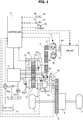
- FIG. 1 is a schematic configuration diagram of a vehicle according to one embodiment of the present invention.
- This vehicle includes an internal combustion engine (hereinafter simply referred to as an "engine") 1 as a driving source.
- a rotative power of the engine 1 is input to a pump impeller 2a of a torque converter 2 including a lock-up clutch 2c via its output shaft to be transmitted to a driving wheel 7 via from a turbine runner 2b to a first gear train 3, a transmission mechanism 4, a second gear train 5, and a differential gear 6.
- the torque converter 2, the first gear train 3, the transmission mechanism 4, and the second gear train 5 constitute an "automatic transmission" according to the embodiment.
- the rotative power of the engine 1, that is, a torque is input to the transmission mechanism 4.
- the transmission mechanism 4 includes a mechanical oil pump 10m driven by using a part of a power of the engine 1 and an electric oil pump 10e driven by receiving an electric power from a battery 13.
- the transmission mechanism 4 includes a hydraulic control circuit 11 that adjusts a pressure of an oil discharged from the mechanical oil pump 10m or the electric oil pump 10e to generate a necessary hydraulic oil pressure and supplies each site of the transmission mechanism 4.
- the electric oil pump 10e is an oil pump smaller than the mechanical oil pump 10m.
- the transmission mechanism 4 includes a belt continuously variable transmission mechanism (hereinafter referred to as a "variator") 20 and a sub-transmission mechanism 30 disposed in series with the variator 20.
- “disposed in series” means that the variator 20 and the sub-transmission mechanism 30 are disposed on an identical power transmission path from the engine 1 to the driving wheel 7.
- the sub-transmission mechanism 30 may be directly coupled to an output shaft of the variator 20 as this embodiment or may be coupled via another transmission or power transmission mechanism (such as, a gear train).
- the variator 20 includes a primary pulley 21, a secondary pulley 22, a V belt 23 stretched around each of the pulleys 21 and 22.
- the variator 20 has a width of a V groove changed corresponding to a hydraulic pressure supplied to a primary pulley oil chamber 21a (hereinafter, referred to as a "primary pulley pressure”) Ppri and a hydraulic pressure supplied to a secondary pulley oil chamber 22a (hereinafter, referred to as a "secondary pulley pressure”) Psec to change a contact radius between the V belt 23 and each of the pulleys 21 and 22, thus steplessly changing a speed ratio Ia of the variator 20.
- a primary pulley pressure a primary pulley oil chamber 21a
- secondary pulley pressure a hydraulic pressure supplied to a secondary pulley oil chamber 22a
- the sub-transmission mechanism 30 is a transmission mechanism having two stages for forward and one stage for backward.
- the sub-transmission mechanism 30 includes a Ravigneaux type planetary gear mechanism 31 and a plurality of friction engaging elements (a Low brake 32, a High clutch 33, and a Rev brake 34).
- the Ravigneaux type planetary gear mechanism 31 couples carriers of two planetary gears.
- the friction engaging elements are coupled to a plurality of rotating elements constituting the Ravigneaux type planetary gear mechanism 31 to change a linking state of these. Adjusting the hydraulic pressure supplied to the respective friction engaging elements 32 to 34 to change engaging or disengaging states of the respective friction engaging elements 32 to 34 ensures changing a speed ratio Is of the sub-transmission mechanism 30.
- a gear position of the sub-transmission mechanism 30 is a first speed stage.
- the gear position of the sub-transmission mechanism 30 is a second speed stage where a speed ratio is smaller than the first speed stage.
- the gear position of the sub-transmission mechanism 30 is a reverse gear.
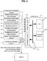
- a controller 12 is the controller 12 that integrally controls an operation of the engine 1 and the transmission mechanism 4. As illustrated in FIG. 2 , the controller 12 is constituted of a CPU121, a storage device 122 constituted of a RAM and a ROM, an input interface 123, an output interface 124, and a bus 125 that mutually couples these. The controller 12 constitutes a "control device" according to the embodiment.
- an output signal of an accelerator pedal opening sensor 41 that detects an accelerator pedal opening APO as an operating amount of an accelerator pedal 51 by a driver
- an output signal of a primary rotational speed sensor 42 that detects a primary pulley rotational speed Npri as a rotational speed of the primary pulley 21
- an output signal of a secondary rotational speed sensor 43 that detects a secondary pulley rotational speed Nsec as a rotational speed of the secondary pulley 22
- an output signal of a vehicle speed sensor 44 that detects a vehicle speed VSP
- an output signal of an inhibitor switch 45 that detects a position of a shift lever 50
- an output signal of an engine rotational speed sensor 46 that detects an engine rotational speed Ne as a rotational speed of an output shaft of the engine 1
- an output signal of a turbine rotational speed sensor 47 that detects a turbine rotational speed Nt as a rotational speed of an output shaft of the torque converter 2
- an output signal from a brake fluid pressure sensor 48 that detects
- the storage device 122 stores a control program for the engine 1, a shift control program for the transmission mechanism 4, and various maps and tables used for these programs.
- the CPU 121 reads and runs the programs stored in the storage device 122, performs various operation processes on various signals input through the input interface 123, creates a fuel injection quantity signal, an ignition timing signal, a throttle position signal, and a shift control signal, and outputs the created signals to the engine 1 and the hydraulic control circuit 11 through the output interface 124.
- the storage device 122 appropriately stores various values used for the operation processes by the CPU 121 and the results of the operations.
- the hydraulic control circuit 11 is constituted of a plurality of flow passages and a plurality of hydraulic control valves.
- the hydraulic control circuit 11 controls the plurality of hydraulic control valves to switch a supply passage for the hydraulic pressure on the basis of a shift control signal from the controller 12. Additionally, the hydraulic control circuit 11 prepares a necessary hydraulic pressure from the pressure of the oil discharged from the mechanical oil pump 10m or the electric oil pump 10e and supplies this hydraulic pressure to each site of the transmission mechanism 4. This changes the speed ratio Ia of the variator 20 and the speed ratio Is of the sub-transmission mechanism 30, shifting the transmission mechanism 4.
- a learning regarding a hydraulic control of the friction engaging elements 32 to 34 is executed during the vehicle stop. Specifically, a hydraulic pressure at which the Low brake 32 starts to transmit a torque when the Low brake 32 of the sub-transmission mechanism 30 is engaged from a disengaged state is learned while the Low brake 32 is disengaged.
- this hydraulic pressure learning will be described in details.
- the hydraulic pressure learning is executed during a neutral idle control (hereinafter, referred to as an "N idle control") that disengages the Low brake 32 for the purpose of an improved fuel efficiency by a decreased load to the engine 1 when the vehicle is stopped in a state where the shift lever 50 is in a traveling range, for example, a D (drive) range.
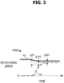
- N idle control When the N idle control is executed and the hydraulic pressure of the Low brake 32 is lowered, as illustrated in FIG. 3 , an engine rotational speed Ne and a turbine rotational speed Nt change with an elapse of time.
- the engine rotational speed Ne is indicated by a solid line and the turbine rotational speed Nt is indicated by a dashed line.
- the N idle control is executed by disengaging the High clutch 33 in the case where the High clutch 33 is engaged when the vehicle stops.
- the deviation ⁇ N1 which will be described later in details, is stored in the controller 12.
- the predetermined rotational speed difference ⁇ N2 is preliminarily set by an experiment and the like.
- the turbine rotational speed Nt is an index of a rotation behavior or a rotational speed of the variator 20.
- Decreasing the predetermined rotational speed difference ⁇ N2 does not apply a sufficient hydraulic pressure to the Low brake 32 even though the learned hydraulic pressure Ple is supplied to the Low brake 32 as the initial hydraulic pressure when the Low brake 32 is engaged; therefore, the piston stroke of the Low brake 32 does not finish and the torque capacity is not generated in the Low brake 32.
- the Low brake 32 is possibly engaged suddenly to cause an engagement shock when the hydraulic pressure supplied to the Low brake 32 increases thereafter.
- the predetermined rotational speed difference ⁇ N2 is set taking such points into consideration.
- the predetermined rotational speed difference ⁇ N2 is set in view of the above-described aspects, it is concerned that the engagement shock is caused when the Low brake 32 is engaged and the durability is lowered as long as the learning accuracy is insufficient.
- the deviation ⁇ N1 is a rotational speed difference between the engine rotational speed Ne and the turbine rotational speed Nt when the shift lever 50 is in the N range or the P range.
- the hydraulic pressure is discharged from the Low brake 32 through a manual valve to disengage the Low brake 32.
- the lock-up clutch 2c is disengaged. Therefore, when the shift lever 50 is in the N range or the P range and a predetermined time Tp elapses after the hydraulic pressure of the Low brake 32 is lowered, the rotational speed difference Nd between the engine rotational speed Ne and the turbine rotational speed Nt converges to a certain rotational speed difference.
- the converged rotational speed difference Nd is stored in the controller 12 as the deviation ⁇ N1. It should be noted that when the deviation ⁇ N1 is obtained by an operation, states of the variator 20 and the torque converter 2 are set to states identical to that at the time of the above-described learning and the operation value of the deviation ⁇ N1 is stored so as to be used in the learning.
- the variator 20 is controlled such that the speed ratio Ia of the variator 20 becomes the Lowest.
- a target speed ratio It of the variator 20 is set to a speed ratio on the Low side with respect to the Lowest speed ratio and in a state where a movable pulley of the primary pulley 21 abuts on a stopper, that is, the mechanical largest speed ratio, which is a mechanically settable largest speed ratio.
- an actual speed ratio Ia of the variator 20 is controlled to match this target speed ratio It .
- the actual speed ratio Ia does not become the mechanical largest speed ratio even when the target speed ratio It is set to the mechanical largest speed ratio.
- the engine rotational speed Ne is low and the amount of oil discharged by the mechanical oil pump 10m is small; therefore, the hydraulic pressure supplied to the variator 20 is low to make the actual speed ratio Ia difficult to reach the mechanical largest speed ratio.
- a command of downshift is continued to be output by the feedback control.
- the friction in the variator 20 varies, thereby varying the deviation ⁇ N1.
- the secondary pulley pressure Psec generates a sandwiching force so as not to cause a belt slip in the variator 20; therefore, the variation of the secondary pulley pressure Psec has a large influence on the friction in the variator 20 and a large influence on the variation of the deviation ⁇ N1.
- the learning control according to the embodiment will be described with reference to a flowchart in FIG. 4 .
- the controller 12 executes a shift control of the variator 20.
- the shift control is a control that shifts the variator 20 on the basis of the preliminarily set shift map.
- the speed ratio Ia of the variator 20 is controlled toward the mechanical largest speed ratio.
- Step S101 the controller 12 determines whether the shift lever 50 is in the D range. When the shift lever 50 is not in the D range, the process proceeds to Step S102. When the shift lever 50 is in the D range, the process proceeds to Step S107.
- Step S102 the controller 12 determines whether the shift lever 50 is in the N range or the P range.
- the process proceeds to Step S103.
- the shift lever 50 is not in the N range or the P range, the current process is terminated.
- the hydraulic pressure is discharged from the Low brake 32 through the manual valve (not illustrated). This disengages the Low brake 32.
- the controller 12 sets the target speed ratio It of the variator 20 to a predetermined speed ratio Ip on the High side with respect to the mechanical largest speed ratio.
- the speed ratio Ip is a minimum value that the actual speed ratio Ia can take (the value on the Highest side) when a thrust ratio of the primary pulley 21 to the secondary pulley 22 is a thrust ratio to achieve the mechanical largest speed ratio.
- the actual speed ratio Ia is not constant and varies corresponding to a variation of a unit, an oil temperature, a deterioration of an oil, and the like even when the thrust ratio is made constant. Therefore, the speed ratio Ia that the variator 20 can actually take in the thrust ratio set to achieve the mechanical largest speed ratio is preliminarily obtained by, for example, an experiment, and the minimum value among them is set as the predetermined speed ratio Ip.
- Step S104 the controller 12 sets a lower limit pressure Psec_lim of the secondary pulley pressure Psec to a predetermined lower limit pressure Ppsec.
- the predetermined lower limit pressure Ppsec is the higher value of the first predetermined pressure P1 and the second predetermined pressure P2.
- the first predetermined pressure P1 is a pressure that generates a torque capacity larger than a lower limit value of the torque capacity that does not cause the belt slip with respect to an input torque Tin transmitted from the engine 1 and input to the variator 20.
- the input torque Tin is a torque output from the engine 1 in the idle state. That is, the first predetermined pressure P1 is a pressure that generates the sandwiching force that does not cause the belt slip with respect to the engine torque in the idle state input to the variator 20.
- the input torque Tin is operated from a turbine torque Tt.
- the turbine torque Tt can be calculated from an equation (1).
- the input torque Tin is calculated as a value that the turbine torque Tt is multiplied by the speed ratio of the first gear train 3.
- Tt ⁇ ⁇ Ne 2 ⁇ t
- the ⁇ is a torque capacity coefficient and the t is a torque ratio.
- the engine rotational speed Ne detected by the engine rotational speed sensor 46 has a small variation width; therefore, a variation width of the turbine torque Tt is also small. Therefore, a belt capacity that does not cause the belt slip with respect to the input torque Tin and a variation width of the secondary pulley pressure Psec that generates the belt capacity are small. This ensures lowering the first predetermined pressure P1.
- the second predetermined pressure P2 is the secondary pulley pressure Psec necessary for achieving the target speed ratio It when the primary pulley pressure Ppri becomes the lower limit pressure Ppri_lim that prevents the belt slip.
- the primary pulley pressure Ppri can be the lower limit pressure Ppri_lim that prevents the belt slip.
- the downshift of the variator 20 is performed by executing one or both of lowering the primary pulley pressure Ppri and increasing the secondary pulley pressure Psec to generate a differential pressure between the primary pulley pressure Ppri and the secondary pulley pressure Psec.
- a fuel consumption quantity or a power consumption quantity increases. Therefore, from the aspect of the fuel consumption quantity and the power consumption quantity, the downshift is preferred to be executed by lowering the primary pulley pressure Ppri.
- the primary pulley pressure Ppri when the primary pulley pressure Ppri is excessively lowered, the belt slip is caused in the primary pulley 21. Accordingly, the lower limit pressure Ppri_lim is set for the primary pulley pressure Ppri such that the belt slip is not caused in the primary pulley 21. Therefore, when the downshift is executed by lowering the primary pulley pressure Ppri, the primary pulley pressure Ppri sometimes becomes the lower limit pressure Ppri_lim.
- the second predetermined pressure P2 is the secondary pulley pressure Psec that achieves the target speed ratio It in a state where the primary pulley pressure Ppri is the lower limit pressure Ppri_lim. That is, in the case where the secondary pulley pressure Psec is the second predetermined pressure P2, the speed ratio Ia of the variator 20 can be the target speed ratio It without causing the belt slip even when the primary pulley pressure Ppri becomes the lower limit pressure Ppri_lim.
- the controller 12 controls the primary pulley pressure Ppri and the secondary pulley pressure Psec on the basis of the target speed ratio It .
- the target speed ratio It is set to the predetermined speed ratio Ip
- the primary pulley pressure Ppri and the secondary pulley pressure Psec are controlled such that the speed ratio Ia of the variator 20 becomes the predetermined speed ratio Ip.
- the lower limit pressure Psec_lim of the secondary pulley pressure Psec is set to the predetermined lower limit pressure Ppsec, when the secondary pulley pressure Psec is lower than the predetermined lower limit pressure Ppsec, the secondary pulley pressure Psec is controlled to be the predetermined lower limit pressure Ppsec or more.
- Step S106 the controller 12 calculates the rotational speed difference Nd between the engine rotational speed Ne and the turbine rotational speed Nt and stores the calculated rotational speed difference Nd as the deviation ⁇ N1. It should be noted that after the predetermined time Tp at which the rotational speed difference Nd between the engine rotational speed Ne and the turbine rotational speed Nt stabilizes is elapsed, the process may be proceeded to Step S106.
- the controller 12 determines whether an execution condition of the N idle control is satisfied.
- the execution condition is satisfied, for example, when the vehicle speed VSP is equal to or less than the predetermined vehicle speed V1 and the brake pedal 52 is pressed.
- the predetermined vehicle speed V1 is set to, for example, 2km/h as a value with which the vehicle stop can be determined.
- the N idle control is executed and the process proceeds to Step S108.
- the execution condition is not satisfied, the current process is terminated.
- the execution of the N idle control lowers the hydraulic pressure of the Low brake 32.
- the controller 12 sets the target speed ratio It of the variator 20 to the predetermined speed ratio Ip on the High side with respect to the mechanical largest speed ratio.
- the predetermined speed ratio Ip is a speed ratio having a value identical to the predetermined speed ratio Ip set at Step S103.
- the controller 12 sets the lower limit pressure Psc_lim of the secondary pulley pressure Psec to the predetermined lower limit pressure Ppsec.
- the predetermined lower limit pressure Ppsec is a pressure having a magnitude identical to the predetermined lower limit pressure Ppsec set at Step S104.
- Step S110 the controller 12 controls the primary pulley pressure Ppri and the secondary pulley pressure Psec on the basis of the target speed ratio It .
- setting the lower limit pressure Psc_lim of the secondary pulley pressure Psec to be the hydraulic pressure equal to or more than the predetermined lower limit pressure Ppsec ensures generating the differential pressure that achieves the downshift based on the target speed ratio It only by lowering the primary pulley pressure Ppri without increasing the secondary pulley pressure Psec even when the downshift is performed. Even in the case where the primary pulley pressure Ppri becomes the lower limit pressure Ppri_lim, the differential pressure necessary for the downshift is obtained and the speed ratio Ia of the variator 20 becomes the target speed ratio It (the predetermined speed ratio Ip ).
- Step S111 the controller 12 determines whether the rotational speed difference Nd between the engine rotational speed Ne and the turbine rotational speed Nt is equal to or less than a deviation ⁇ N calculated by adding the predetermined rotational speed difference ⁇ N2 to the deviation ⁇ N1.
- the process proceeds to Step S112.
- the deviation ⁇ N1 is a value stored at Step S106.
- the controller 12 obtains the learned hydraulic pressure Ple.
- the controller 12 lowers the hydraulic pressure of the Low brake 32 by the execution of the N idle control, specifies a hydraulic pressure command value of the Low brake 32 at the time point when the rotational speed difference Nd becomes the deviation ⁇ N, and stores this as the hydraulic pressure (the learned hydraulic pressure) Ple at which the Low brake 32 starts the torque transmission.
- Making the contents of the process at Step S103 to Step S105 identical to the contents of the process at Step S108 to Step S110 ensures using the stored deviation ⁇ N1 at the time of the learning (when the learned hydraulic pressure Ple is obtained).
- the target speed ratio It is set to the predetermined speed ratio Ip and furthermore, the lower limit pressure Psec_lim of the secondary pulley pressure Psec is set to the predetermined lower limit pressure Ppsec to reduce the variation of the friction in the variator 20. Then, the deviation ⁇ N1 is calculated and stored in a state where the variation is reduced with this, and the learning is executed using the stored deviation ⁇ N1. Regardless of whether the variator 20 downshifts or upshifts, the speed ratio Ia of the variator 20 can be controlled toward the target speed ratio It without changing the secondary pulley pressure Psec.
- the deviation ⁇ N1 is calculated and stored in a state where the variation of the secondary pulley pressure Psec having a large influence on the variation of the friction in the variator 20 and the variation of the deviation ⁇ N1, and the learning is executed using the stored deviation ⁇ N1. Therefore, the learning can be stably executed, thereby ensuring improving the learning accuracy of the hydraulic pressure Ple.
- the stored learned hydraulic pressure Ple is used as the initial hydraulic pressure supplied to the Low brake 32 when the Low brake 32 is reengaged thereafter.
- the target speed ratio It is decreased with respect to the mechanical largest speed ratio and set to the speed ratio on the High side. This ensures reducing continuing the lowering command of the primary pulley pressure Ppri or the increasing command of the secondary pulley pressure Psec by the feedback control to cause the speed ratio Ia of the variator 20 to be the target speed ratio It despite the difficulty of achieving the target speed ratio It due to a shortage of a pump discharging amount and the like. Accordingly, the variations of the primary pulley pressure Ppri and the secondary pulley pressure Psec are reduced to ensure reducing the variation of the friction in the variator 20. Therefore, the learning accuracy regarding the hydraulic control of the friction engaging element (here, the Low brake 32) can be improved.
- the target speed ratio It is set to a minimum value that the actual speed ratio Ia of the variator 20 can take, in other words, the predetermined speed ratio Ip on the Highest side.
- This causes the variation to be on the Low side with respect to the target speed ratio Ip even though the variation with respect to the target speed ratio It is present in the actual speed ratio Ia after the above-described thrust ratio is achieved; therefore, later shifting to achieve the target speed ratio Ip becomes the upshift.
- This ensures achieving the target speed ratio Ip by increasing the primary pulley pressure Ppri without varying the secondary pulley pressure Psec; therefore, the variation of the secondary pulley pressure Psec can be reduced. Accordingly, the variation of the friction of the variator 20 is reduced to ensure reducing the variation of the deviation ⁇ N1, thereby ensuring the improved learning accuracy.
- the lower limit pressure Psec_lim of the secondary pulley pressure Psec is caused to be the first predetermined pressure P1 larger than the lower limit value that generates the belt capacity for transmitting the input torque Tin transmitted from the engine 1 without causing the belt slip in the variator 20.
- This causes the secondary pulley pressure Psec to be in a state higher than the first predetermined pressure P1 at the time of the learning and the calculation of the deviation ⁇ N, and the secondary pulley pressure Psec increases when the learned hydraulic pressure Ple is actually obtained to ensure avoiding the variation of the friction of the variator 20. Accordingly, the variation of the deviation ⁇ N1 is reduced with more certainty, thereby ensuring the improved learning accuracy.
- the input torque Tin input to the variator 20 is operated on the basis of the turbine torque Tt.
- the torque signal from the engine 1 can be used for the input torque Tin.
- the torque signal from the engine 1 has a large variation width
- the turbine torque Tt can be calculated on the basis of the engine rotational speed Ne and the variation width is smaller than that of the torque signal from the engine 1.
- operating the input torque Tin on the basis of the turbine torque Tt ensures reducing the variation width of the input torque Tin to small, thereby ensuring setting the lower limit pressure Psec_lim of the secondary pulley pressure Psec to low. This ensures the improved fuel consumption quantity and power consumption quantity.
- the lower limit pressure Psec_lim of the secondary pulley pressure Psec is caused to be the second predetermined pressure P2 that causes the speed ratio Ia of the variator 20 to be close to the target speed ratio It under the lower limit pressure Ppri_lim of the primary pulley pressure Ppri that does not cause the belt slip in the primary pulley 21. This ensures generating the differential pressure necessary for the downshift only by lowering the primary pulley pressure Ppri when the speed ratio Ia of the variator 20 is changed to the target speed ratio It .
- the variation of the friction of the variator 20 is reduced to ensure reducing the variation of the deviation ⁇ N1, thereby ensuring the improved learning accuracy.
- the differential pressure is generated between the primary pulley pressure Ppri and the secondary pulley pressure Psec by lowering the primary pulley pressure Ppri.
- the lower limit pressure Ppri_lim is set in order to reduce the belt slip, thus incapable of decreasing the primary pulley pressure Ppri with respect to the lower limit pressure Ppri_lim. In order to continue the downshift in such a case, it is necessary to increase the secondary pulley pressure Psec.
- the secondary pulley pressure Psec has a large influence on the variation of the friction of the variator 20
- the secondary pulley pressure Psec is increased at the time of the learning and the calculation of the deviation ⁇ N
- the friction of the variator 20 and the deviation ⁇ N vary and the learning cannot be stably executed.
- the lower limit pressure Psec_lim of the secondary pulley pressure Psec is set to the predetermined lower limit pressure Ppsec to increase the secondary pulley pressure Psec. This ensures generating the differential pressure only by lowering the primary pulley pressure Ppri even when the variator 20 downshifts. Therefore, without the necessity of increasing the secondary pulley pressure Psec having a large influence on the variation of the friction of the variator 20, the variations of the friction and the deviation ⁇ N1 can be reduced, thereby ensuring the improved learning accuracy.
- the higher one out of the first predetermined pressure P1 and the second predetermined pressure P2 is set to be the predetermined lower limit pressure Ppsec of the secondary pulley 22, only one of the first predetermined pressure P1 or the second predetermined pressure P2 may be set as the predetermined lower limit pressure Ppsec.
- an electric motor may be used instead of the engine 1 or a combination of the internal combustion engine and the electric motor may be used.
- the electric motor may be one that only has a function of an engine or may be a motor-generator that doubles functions of an engine and an electric generator.
- the learning control described above is also applicable to a control of an automatic transmission including a forward/reverse switching mechanism instead of the sub-transmission mechanism 30.
- the learning may be executed by sequentially storing the hydraulic pressure command values with respect to the engine rotational speed Ne, the turbine rotational speed Nt, and the Low brake 32, calculating the deviation ⁇ N1 on the basis of the stored engine rotational speed Ne and turbine rotational speed Nt after the disengagement of the Low brake 32 is completed, and calculating the learned hydraulic pressure Ple by using the calculated deviation ⁇ N1 and predetermined rotational speed difference ⁇ N2.
- the learning target is not limited to this, and may be another friction engaging element, for example, a hydraulic control of the High clutch 33.
- the hydraulic pressure command value at which the High clutch 33 starts to transmit the torque is specified from the deviation between the engine rotational speed Ne and the turbine rotational speed Nt when the High clutch 33 is disengaged during the vehicle stop, and this is stored as the learned hydraulic pressure. Then, the stored learned hydraulic pressure is supplied to the High clutch 33 as the initial hydraulic pressure when the High clutch 33 is reengaged thereafter.
- the target speed ratio is set to the mechanical largest speed ratio in order to cause the speed ratio of the variator 20 to be close to the Lowest speed ratio.
- the target speed ratio is decreased with respect to the mechanical largest speed ratio and set to the High side.
- the target speed ratio is not set to the High side but set to the mechanical largest speed ratio to control the actual speed ratio.
Landscapes
- Engineering & Computer Science (AREA)
- General Engineering & Computer Science (AREA)
- Mechanical Engineering (AREA)
- Control Of Transmission Device (AREA)
Applications Claiming Priority (2)
| Application Number | Priority Date | Filing Date | Title |
|---|---|---|---|
| JP2015178441 | 2015-09-10 | ||
| PCT/JP2016/076337 WO2017043543A1 (ja) | 2015-09-10 | 2016-09-07 | 自動変速機の制御装置および自動変速機の制御方法 |
Publications (2)
| Publication Number | Publication Date |
|---|---|
| EP3348873A1 true EP3348873A1 (de) | 2018-07-18 |
| EP3348873A4 EP3348873A4 (de) | 2018-11-07 |
Family
ID=58239871
Family Applications (1)
| Application Number | Title | Priority Date | Filing Date |
|---|---|---|---|
| EP16844404.0A Withdrawn EP3348873A4 (de) | 2015-09-10 | 2016-09-07 | Vorrichtung zur steuerung eines automatikgetriebes und verfahren zur steuerung eines automatikgetriebes |
Country Status (6)
| Country | Link |
|---|---|
| US (1) | US10527161B2 (de) |
| EP (1) | EP3348873A4 (de) |
| JP (1) | JP6500115B2 (de) |
| KR (1) | KR101999935B1 (de) |
| CN (1) | CN108027046B (de) |
| WO (1) | WO2017043543A1 (de) |
Families Citing this family (2)
| Publication number | Priority date | Publication date | Assignee | Title |
|---|---|---|---|---|
| WO2020059339A1 (ja) * | 2018-09-21 | 2020-03-26 | ジヤトコ株式会社 | ベルト式無段変速機 |
| JP7272811B2 (ja) * | 2019-02-13 | 2023-05-12 | 株式会社Subaru | 無段変速機の制御装置 |
Family Cites Families (16)
| Publication number | Priority date | Publication date | Assignee | Title |
|---|---|---|---|---|
| DE19622108A1 (de) * | 1996-06-01 | 1997-12-04 | Zahnradfabrik Friedrichshafen | Verfahren zur Steuerung eines CVT |
| JP3606153B2 (ja) | 2000-03-22 | 2005-01-05 | 三菱自動車工業株式会社 | 車両用自動変速機のクリープ力制御装置 |
| JP3606157B2 (ja) | 2000-03-31 | 2005-01-05 | 三菱自動車工業株式会社 | 車両用自動変速機のクリープ力制御装置 |
| JP2004052643A (ja) | 2002-07-18 | 2004-02-19 | Toyota Motor Corp | 車両のニュートラル制御装置 |
| JP2004190756A (ja) | 2002-12-10 | 2004-07-08 | Toyota Motor Corp | 自動変速機の制御装置 |
| JP4774108B2 (ja) * | 2009-03-02 | 2011-09-14 | 日産自動車株式会社 | 自動変速機の制御装置 |
| RU2508487C1 (ru) * | 2010-02-23 | 2014-02-27 | Ниссан Мотор Ко., Лтд. | Устройство управления бесступенчатой трансмиссии для транспортного средства |
| JP5455790B2 (ja) | 2010-05-28 | 2014-03-26 | ダイハツ工業株式会社 | 発進クラッチ制御装置 |
| JP5379097B2 (ja) * | 2010-09-08 | 2013-12-25 | ジヤトコ株式会社 | 無段変速機及びパワーon/off判定方法 |
| JP5474857B2 (ja) * | 2011-03-23 | 2014-04-16 | ジヤトコ株式会社 | 無段変速機搭載車の制御装置 |
| CN104641155B (zh) * | 2012-09-27 | 2016-09-21 | 加特可株式会社 | 无级变速器及其控制方法 |
| TW201508223A (zh) * | 2013-08-20 | 2015-03-01 | 隆達電子股份有限公司 | 發光裝置 |
| JP6196857B2 (ja) | 2013-09-13 | 2017-09-13 | ジヤトコ株式会社 | 車両の制御装置 |
| JP5993357B2 (ja) * | 2013-09-13 | 2016-09-14 | ジヤトコ株式会社 | 車両の制御装置 |
| US9183828B2 (en) * | 2014-03-24 | 2015-11-10 | Yuk King Monica Ng | Noise control panels to provide a noise-free environment for infants |
| US10507832B2 (en) * | 2015-08-25 | 2019-12-17 | Jatco Ltd | Vehicle drive control device and control method for vehicle drive control device |
-
2016
- 2016-09-07 CN CN201680051748.1A patent/CN108027046B/zh active Active
- 2016-09-07 JP JP2017539201A patent/JP6500115B2/ja active Active
- 2016-09-07 US US15/757,841 patent/US10527161B2/en active Active
- 2016-09-07 KR KR1020187005721A patent/KR101999935B1/ko not_active Expired - Fee Related
- 2016-09-07 WO PCT/JP2016/076337 patent/WO2017043543A1/ja not_active Ceased
- 2016-09-07 EP EP16844404.0A patent/EP3348873A4/de not_active Withdrawn
Also Published As
| Publication number | Publication date |
|---|---|
| CN108027046B (zh) | 2020-02-14 |
| JP6500115B2 (ja) | 2019-04-10 |
| KR20180033281A (ko) | 2018-04-02 |
| KR101999935B1 (ko) | 2019-07-12 |
| US20180355969A1 (en) | 2018-12-13 |
| EP3348873A4 (de) | 2018-11-07 |
| WO2017043543A1 (ja) | 2017-03-16 |
| CN108027046A (zh) | 2018-05-11 |
| JPWO2017043543A1 (ja) | 2018-06-14 |
| US10527161B2 (en) | 2020-01-07 |
Similar Documents
| Publication | Publication Date | Title |
|---|---|---|
| KR101647513B1 (ko) | 무단 변속기 및 그 제어 방법 | |
| US8271167B2 (en) | Shift control apparatus for vehicular continuously variable transmissions | |
| US8666616B2 (en) | Continuously variable transmission and control method therefore | |
| US20080119308A1 (en) | Control device and control method for continuously variable transmission | |
| US8718883B2 (en) | Continuously variable transmission and power on/off determination method | |
| EP3175149B1 (de) | Steuerungsvorrichtung für fahrzeug | |
| EP2458239A1 (de) | Fahrzeugsteuersystem und zugehöriges Steuerverfahren | |
| RU2640940C1 (ru) | Система привода транспортного средства, устройство управления системой привода транспортного средства и способ управления системой привода транспортного средства | |
| US20150148157A1 (en) | Continuously variable transmission and a hydraulic control method thereof | |
| KR20160102517A (ko) | 무단 변속기의 제어 장치 | |
| US8353799B2 (en) | Control of and control method for vehicle continuously variable transmission | |
| US10697540B2 (en) | Vehicle control device and vehicle control method | |
| US10527161B2 (en) | Control device for automatic transmission and control method for automatic transmission | |
| US9416873B2 (en) | Continuously variable transmission and control method therefor | |
| JP5765188B2 (ja) | 車両用無段変速機の制御装置 | |
| US10821984B2 (en) | Gear shift control device and gear shift control method for continuously variable transmission | |
| EP3369969B1 (de) | Fahrzeugsteuerungsvorrichtung und fahrzeugsteuerungsverfahren | |
| US11524670B2 (en) | Control device for vehicle and control method for vehicle | |
| US11365805B2 (en) | Control device for vehicle and control method for vehicle | |
| US10005445B2 (en) | Hydraulic control device for automatic transmission and control method therefor | |
| US20240102552A1 (en) | Continuously variable transmission, method for controlling continuously variable transmission, and non-transitory computer-readable medium | |
| US10907731B2 (en) | Control device for power transmission mechanism |
Legal Events
| Date | Code | Title | Description |
|---|---|---|---|
| STAA | Information on the status of an ep patent application or granted ep patent |
Free format text: STATUS: THE INTERNATIONAL PUBLICATION HAS BEEN MADE |
|
| PUAI | Public reference made under article 153(3) epc to a published international application that has entered the european phase |
Free format text: ORIGINAL CODE: 0009012 |
|
| STAA | Information on the status of an ep patent application or granted ep patent |
Free format text: STATUS: REQUEST FOR EXAMINATION WAS MADE |
|
| 17P | Request for examination filed |
Effective date: 20180302 |
|
| AK | Designated contracting states |
Kind code of ref document: A1 Designated state(s): AL AT BE BG CH CY CZ DE DK EE ES FI FR GB GR HR HU IE IS IT LI LT LU LV MC MK MT NL NO PL PT RO RS SE SI SK SM TR |
|
| AX | Request for extension of the european patent |
Extension state: BA ME |
|
| A4 | Supplementary search report drawn up and despatched |
Effective date: 20181005 |
|
| RIC1 | Information provided on ipc code assigned before grant |
Ipc: F16H 61/66 20060101ALI20180929BHEP Ipc: F16H 61/20 20060101ALI20180929BHEP Ipc: F16H 61/662 20060101ALI20180929BHEP Ipc: F16H 61/02 20060101AFI20180929BHEP Ipc: F16H 61/00 20060101ALI20180929BHEP Ipc: F16H 59/22 20060101ALI20180929BHEP |
|
| STAA | Information on the status of an ep patent application or granted ep patent |
Free format text: STATUS: THE APPLICATION HAS BEEN WITHDRAWN |
|
| 18W | Application withdrawn |
Effective date: 20181112 |
|
| DAV | Request for validation of the european patent (deleted) | ||
| DAX | Request for extension of the european patent (deleted) |