EP3347702B1 - Anordnung zur bestimmung der erreichbaren haftfestigkeit vor ausbildung einer stoffschlüssigen verbindung an einer oberfläche eines fügepartners - Google Patents
Anordnung zur bestimmung der erreichbaren haftfestigkeit vor ausbildung einer stoffschlüssigen verbindung an einer oberfläche eines fügepartners Download PDFInfo
- Publication number
- EP3347702B1 EP3347702B1 EP16762757.9A EP16762757A EP3347702B1 EP 3347702 B1 EP3347702 B1 EP 3347702B1 EP 16762757 A EP16762757 A EP 16762757A EP 3347702 B1 EP3347702 B1 EP 3347702B1
- Authority
- EP
- European Patent Office
- Prior art keywords
- electromagnetic radiation
- detectors
- arrangement according
- arrangement
- joining
- Prior art date
- Legal status (The legal status is an assumption and is not a legal conclusion. Google has not performed a legal analysis and makes no representation as to the accuracy of the status listed.)
- Active
Links
Images
Classifications
-
- G—PHYSICS
- G01—MEASURING; TESTING
- G01N—INVESTIGATING OR ANALYSING MATERIALS BY DETERMINING THEIR CHEMICAL OR PHYSICAL PROPERTIES
- G01N19/00—Investigating materials by mechanical methods
- G01N19/04—Measuring adhesive force between materials, e.g. of sealing tape, of coating
-
- G—PHYSICS
- G01—MEASURING; TESTING
- G01N—INVESTIGATING OR ANALYSING MATERIALS BY DETERMINING THEIR CHEMICAL OR PHYSICAL PROPERTIES
- G01N21/00—Investigating or analysing materials by the use of optical means, i.e. using sub-millimetre waves, infrared, visible or ultraviolet light
- G01N21/17—Systems in which incident light is modified in accordance with the properties of the material investigated
- G01N21/21—Polarisation-affecting properties
-
- G—PHYSICS
- G01—MEASURING; TESTING
- G01N—INVESTIGATING OR ANALYSING MATERIALS BY DETERMINING THEIR CHEMICAL OR PHYSICAL PROPERTIES
- G01N21/00—Investigating or analysing materials by the use of optical means, i.e. using sub-millimetre waves, infrared, visible or ultraviolet light
- G01N21/17—Systems in which incident light is modified in accordance with the properties of the material investigated
- G01N21/55—Specular reflectivity
-
- G—PHYSICS
- G01—MEASURING; TESTING
- G01N—INVESTIGATING OR ANALYSING MATERIALS BY DETERMINING THEIR CHEMICAL OR PHYSICAL PROPERTIES
- G01N21/00—Investigating or analysing materials by the use of optical means, i.e. using sub-millimetre waves, infrared, visible or ultraviolet light
- G01N21/17—Systems in which incident light is modified in accordance with the properties of the material investigated
- G01N21/59—Transmissivity
-
- G—PHYSICS
- G01—MEASURING; TESTING
- G01N—INVESTIGATING OR ANALYSING MATERIALS BY DETERMINING THEIR CHEMICAL OR PHYSICAL PROPERTIES
- G01N21/00—Investigating or analysing materials by the use of optical means, i.e. using sub-millimetre waves, infrared, visible or ultraviolet light
- G01N21/17—Systems in which incident light is modified in accordance with the properties of the material investigated
- G01N2021/1765—Method using an image detector and processing of image signal
Definitions
- the invention relates to an arrangement for determining the achievable adhesive strength before forming a material-locking connection on a surface of a joining partner.
- Joining partners can be connected to one another in a material-locking manner by gluing, welding or soldering.
- Joining partners can also be connected to one another that are both made of the same material, in particular plastics, metals or ceramics, or of which at least one joining partner is made of a polymer.
- Joining partners made of different materials can also be examined in this way before the material-locking connection is made.
- the invention can also be used to determine the achievable adhesive strength of a coating that is applied to the surface of a component, which will also be referred to below as the joining partner, before the coating is formed.
- Adhesive strength can be understood as the achievable adhesion effect.
- the adhesive strength of coatings is usually determined using a tape test. This can only be carried out after the coating has been formed. It is therefore not possible to predict the adhesive strength. In addition, the coating will be destroyed and the respective substrate will at least be impaired.
- EP 2 138 830 A2 A method for determining the influence of UV radiation on materials using IR spectroscopy is known.
- the arrangement according to the invention for determining the achievable adhesive strength before the formation of a material bond on the surface of a joining partner has several detectors which are used for spatially resolved spectral analysis of electromagnetic radiation within a wavelength interval. These detectors are designed for this purpose in a row or a row and column arrangement. The detectors are connected to an electronic evaluation unit and arranged in such a way that electromagnetic radiation emitted by a broadband radiation source hits the detectors either after being reflected on the surface of one of the joining partners, a layer formed on the surface of a joining partner with which the material-locking connection is formed, and/or after radiating through joining partners that are transparent to the electromagnetic radiation.
- the irradiation takes place in such a way that a homogeneous intensity of the electromagnetic radiation is maintained on a surface from which the electromagnetic radiation is reflected or transmitted through the surface.
- the area to be detected at the same time should therefore be irradiated with homogeneous intensity.
- broadband irradiation electromagnetic waves that lie within a wavelength interval are directed at the respective surface of one of the joining partners that is to be examined.
- the joining partner or a coating formed on the surface, onto whose surface the electromagnetic radiation is directed, is made of a material that does not absorb the respective electromagnetic radiation 100% and thus a transmission and/or reflection of at least 2% of the electromagnetic radiation is possible.
- the electronic evaluation unit is designed in such a way that the measurement signals recorded by the detectors with spatial and wavelength resolution can be assigned to a specific wavelength range within a wavelength interval and to an individual location point within a predeterminable partial area of the irradiated surface.
- the recording and evaluation can be carried out on the entire surface of the joining partner used for the material-locking joining or on all joining partners. However, it is also possible to carry out a determination on one or more partial surfaces.
- the totality of the wavelength-resolved intensities recorded at all locations of the respective irradiated area forms a three-dimensional Data structure consisting of one wavelength-resolved and two spatially resolved dimensions (hypercube).
- a material-locking connection of joining partners examined using the invention should belong to the same class, which should have a comparable structure or composition, as those previously examined using another measuring method.
- the functional relationship between adequately selected sets of features of materially bonded joining partners and their adhesive strengths, which were determined using another measuring method, can be determined, for example, by means of linear or non-linear regression, a partial least square algorithm (PLS), a neural network, a combination of at least two of these methods or other regression methods (regression model).
- PLS partial least square algorithm
- neural network a combination of at least two of these methods or other regression methods (regression model).
- the electronic memory should therefore contain the regression model that was created using the data sets of samples recorded with the arrangement according to the invention that were subjected to data reduction and feature extraction and whose adhesive strengths were determined using a different measuring method. Using a regression model stored in the electronic memory, the adhesive strength of a comparable examined sample of the same sample class with comparable structure.
- the electronic evaluation unit carries out the data reduction and feature extraction of the data sets determined using the arrangement according to the invention.
- the spectral information can be evaluated first and then the location information.
- a reverse order or any combination of more than two individual steps for data reduction and feature extraction is also possible.
- Data reduction and feature extraction can be performed using principal component analysis (PCA), parameterization of texture information, averaging and/or standard deviation determination, and combinations thereof.
- PCA principal component analysis
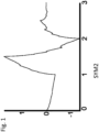
- n intensities of the wavelengths (spectra) of all location points are transformed by a coordinate transformation into a new orthogonal coordinate system - the principal component space - in which the original data have maximum variance, and where n represents the number of measured wavelengths.
- the coordinate transformation is calculated by determining the n eigenvectors (principal components) and the corresponding n eigenvalues of the covariance matrix of the data set of the measured partial area.
- the eigenvector with the lowest eigenvalue is the nth principal component of the data set and does not describe any relevant properties of the data set.
- the coordinates of the spectra in the newly spanned principal component space are the so-called score values, which sufficiently characterize the corresponding location point.
- the electronic evaluation unit can advantageously be used to reduce data and extract features in such a way that the data recorded according to the invention are evaluated in the same way as the data from the samples on the basis of whose known adhesive strengths the regression model was created.
- the adhesive strength of the sample is then determined using the regression model on the basis of the data set recorded according to the invention, the intensities of the electromagnetic radiation recorded with spatial and wavelength resolution.
- the first six main components including the score values are preferably determined using a principal component analysis of the spectral information of all locations of the partial area. Since the data recorded according to the invention represent all locations of an area under investigation, the areal distribution of the score values can be specified for each main component. The different areal distribution of the score values is quantified using various statistical parameters that are determined using all score values of a main component of the respective partial area. In particular, these are the variance, the interquantile distance or the mean absolute deviation. This procedure can be used for all main components.
- the adhesive strength is determined by the electronic evaluation unit on the basis of a regression model, such as a partial least square regression model (PLS), whereby the parameters may have been subjected to another prior feature extraction, preferably via another principal component analysis (PCA).
- PLS partial least square regression model
- the regression model used (here PLS) was previously determined using samples from the same sample class with a comparable structure, whose adhesive strengths were determined using a different measuring method, whereby all steps of feature extraction were carried out analogously to the method described above.
- Variant b) Using a principal component analysis of the spectral information of all recorded location points of the respective partial area under investigation, one or more main components are calculated, in particular the score values of the location points per main component, which can be specified as a distribution over the sample area.
- the location points can be described by various parameters of the score values and displayed as a graphic representation. In addition to the actual score value, this can also be achieved in particular by the parameters that result from a texture analysis of the spatially resolved distribution of the score values.
- a discrete wavelet transformation (DWT) is preferably used for this, whereby, for example, the 'Sym2' wavelet is used to carry out the calculations, and a subsequent calculation of further parameters, e.g.
- the energy signature (sum of squares) of the wavelet parameters is carried out.
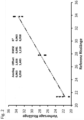
- the calculated parameters determined on the examined surface of the joining partner can be determined using a regression model, in particular a linear regression model.
- the regression model used was previously determined using samples from the same sample class with comparable structure and properties, whose adhesive strengths were determined using a different measuring method, with all steps of the feature extraction being carried out analogously to the method described above.
- the wavelet transformation corresponds to a digital filtering according to high-pass and low-pass frequencies, whereby the filter function (wavelet) can be selected variably. can be and the frequency response is direction-dependent.
- the filter function wavelet
- the result is determined by the low-pass information (wavelet coefficients) and the remaining information is discarded; each pixel represents a wavelet coefficient and all pixels together form the wavelet matrix.
- the WT is performed, the spatial resolution is reduced and information is separated.
- Separating the information means that for an original number of m pixels, m*0.5 pixels are still obtained after the WT.
- the WT can be performed recursively several times. This can be done in three stages to obtain information on the fine, medium-fine and coarse structure of the images. However, more than or fewer than three stages are also possible.
- From the wavelet coefficients of each WT further parameters can be determined to describe structures of the wavelet matrix or to represent them pictorially. Often, the root of the square sum of the coefficients of the wavelet matrix (energy), the entropy and the gray value matrix and parameters derived from them are used.
- the size of an examined area should be in the range of 500 ⁇ m ⁇ 500 ⁇ m to 1500 ⁇ m ⁇ 1500 ⁇ m. Detection should be possible with a spatial resolution in the range of 0.5 ⁇ m to 1.5 ⁇ m, preferably 1 ⁇ m.
- At least 30, preferably at least 100 detectors should be arranged in a row (hyperspectral camera).
- At least one, preferably at least 50 detectors should be arranged in a column.
- a hyperspectral camera with suitable radiation-forming optical elements and electronic evaluation electronics can be used.
- the irradiation of the surface should be at least at an angle in the range of 0° to ⁇ 90° in relation to the normal of the surface on which the electromagnetic radiation strikes.
- Irradiation and detection can also be carried out with a variable angle of incidence of the electromagnetic radiation. As already stated, angles of incidence in the range 0° to a maximum of 89° can be selected.
- the detection can also be limited to linearly polarized electromagnetic radiation.
- an advantageous alignment of one or more polarization planes can be selected before and/or after the irradiated surface.
- the detectors and the respective joining partners that are not yet firmly bonded to one another can be moved relative to one another along at least one axis and preferably at an advantageous distance from one another.
- a sample formed with a joining partner that is not yet firmly bonded can be moved along an axis.
- a suitably movable table on which such a sample is arranged which can be moved in an x- and possibly also in a y-direction.
- unwinding from roll to roll is also possible if the respective sample is formed with one or more flexibly deformable material(s) and is in the form of a film, for example.
- the radiation source can contain elements that shape the electromagnetic radiation.
- the radiation source can be combined with a microscope.
- a radiation source can also be arranged in a hollow body from which the electromagnetic radiation emerges diffusely and can be directed onto the surface to be irradiated.
- the hollow body can be a sphere or cylinder.
- An area to be detected at the same time should be homogeneously irradiated.
- the wavelength range used should be taken into account when selecting the optical elements used for beam shaping.
- the size of the area to be examined and the necessary spatial resolution can be influenced by using elements arranged in front of the detectors that shape the electromagnetic radiation.
- the camera or detector arrangement can be used in combination with a microscope or a telecentric lens.
- an aperture preventing the incidence of scattered electromagnetic radiation can be arranged in front of the detectors in the beam path of the electromagnetic radiation.
- the radiation source can emit electromagnetic radiation whose wavelength range begins in the UV range and ends in the IR range. Radiation from the wavelength range of visible light up to the NIR range is particularly preferred, i.e. from 250 nm to 1000 nm. In a wavelength range used for irradiation, it should be possible to use as many wavelengths as possible within the respective interval. The limits should be determined solely by the sensitivity range of the detectors used in terms of their sensitivity/measurement accuracy of the intensities they can detect for the respective wavelengths and the optical properties of the beam guidance components. Preference should be given to using the spectral ranges that show the greatest variance between the spectra of the samples for determining the adhesive strength and have the smallest possible determination error.
- At least one element with which a targeted selection of the polarization of the electromagnetic radiation can be achieved can also be present or integrated in the beam path.
- a sample of materially bonded joining partners can also be a multi-layer structure, preferably made of different materials.
- the base material the sample can be a polymer film or a thin metal or glass film to which further thin polymer, ceramic or metal layers can be applied in various combinations.
- the achievable adhesive strength can also be determined for more than two joining partners that are to be bonded together. These can be arranged one above the other, for example in the form of a stack. As already mentioned, joining partners can be bonded together by gluing. A suitable adhesion promoter is present between the bonded surfaces of the joining partners. The bond can also have been formed by welding, with or without additional material.
- the achievable adhesive strength can also be determined for a soldered connection.
- the expected adhesive strength of coatings such as paint layers, plastic layers on metal or ceramic surfaces, coatings formed using CVD or PVD processes, can also be determined.
- the detectors used and the electronic evaluation unit, as well as the radiation source if necessary, can represent a so-called imaging hyperspectral system, which can be used in the arrangement according to the invention.
- imaging hyperspectral system which can be used in the arrangement according to the invention.
- texture information can also be obtained for the respective detected part of the sample.
- the invention allows the creation of a statistical model on the basis of which the achievable adhesive strength of the examined surfaces of a and/or both joining partners in the corresponding underlying sub-area can be predicted.
- the data set can be recorded using one of several optical detectors, preferably arranged in series, with which a wavelength- and spatially resolved recording of intensities is possible.
- the achievable bond strength is influenced by the properties of the sample surfaces being examined. These properties can be particles, adsorbates, layer thicknesses, materials, surface roughness, topology, etc. as well as their distribution over the respective partial area being examined. These sample-specific properties also mean that electromagnetic radiation that interacts with the sample is reflected, scattered or transmitted differently (spectrally, intensity). The total of a sufficient number of individual wavelength-resolved intensities (spectra) from different locations of a detected partial area of a sample can thus represent the information about the expected bond strength of a joining partner in the sample area under consideration.
- the bond strength can be determined on the basis of a measured set of characteristics using a regression model previously established with sets of characteristics with known bond strengths measured on samples of the same sample class with comparable structure.
- the measured feature sets must be subjected to data reduction and thus feature extraction.
- the wavelength spectra detected at the individual locations of the respective partial area can be subjected to spectral feature extraction, for example a cluster analysis or principal component analysis.
- the parameters used in the regression model can therefore be the number and distribution of the clusters, the score values of the principal components or their distribution.
- image compression methods can be used for feature extraction for texture evaluation, in which the intensities of individual elements detected at all locations of the respective sub-area are Wavelengths or the sum or the average sum of the intensities of several wavelengths or the parameters determined by a spectral feature reduction and/or their combinations are subjected to image compression.
- at least one parameter should be determined using a wavelet transformation or another image compression method, such as Taylor polynomials, Fourier and cosine transformations, discrete cosine transformation or gray value matrix method.
- the adhesion strength of partial surfaces can be predicted on the basis of a calibration model (regression model) that was created using measured data sets from samples of the same sample class with a comparable structure and known adhesion strength, whereby the measured data sets are treated for calibration and prediction using identical steps of feature reduction.
- a calibration model regression model
- MLRA multiple linear regression analysis
- PCR principal component regression
- PLS partial least squares regression
- neural network a “neural network”
- Prerequisites for sufficient determination accuracy are homogeneous illumination of the area used for detection, so that superposition of the intensity fluctuations caused by the sample with lateral fluctuations in the illumination intensity can be avoided by implementing a laterally homogeneous light field.
- Microscope optics can be used advantageously for small sample areas.
- the arrangement according to the invention can be adapted to the respective area of the sample to be detected by using different optics, working distances and magnifications.
- the invention enables the determination of achievable adhesive strengths of samples to be carried out within a few milliseconds to minutes instead of days.
- a contactless, non-destructive measurement is possible.
- the samples do not need to be additionally treated or otherwise prepared. It is preferably used in quality control and in inline monitoring of production, so that in these cases no sampling and separate determination is necessary.
- Sample sheets made of a titanium alloy that were coated with around 100 nm of silicon dioxide using a plasma process were divided into five sub-areas on a selected area of 2 mm * 10 mm and homogeneously irradiated using a halogen lamp as a light source.
- a total of 1000 ⁇ 150 optical detectors were arranged in a row-column arrangement above the sample and combined with optics (here a microscope) so that the entire sample area could be recorded with wavelength and location resolution over a width of 2 mm.
- the optical detectors were used to record the intensities of the light reflected from the sample for individual locations with wavelength resolution.
- a total of 150 wavelengths in the range 400 nm to 1000 nm were taken into account.
- the sample was moved perpendicular to the row arrangement of detectors in order to record the entire sample area.
- the intensities recorded with the detectors for the individual locations with wavelength resolution were assigned to sub-areas of the sample, each with a size of 2 mm * 2 mm, and form a hypercube.
- the achievable adhesive strength of the sample under investigation was determined using the regression model that had been created beforehand using data sets of partial areas with known adhesive strength and data treatment analogous to that described in steps 1-4 and stored in the electronic memory of the electronic evaluation unit.
Landscapes
- Physics & Mathematics (AREA)
- Health & Medical Sciences (AREA)
- Life Sciences & Earth Sciences (AREA)
- Chemical & Material Sciences (AREA)
- Analytical Chemistry (AREA)
- Biochemistry (AREA)
- General Health & Medical Sciences (AREA)
- General Physics & Mathematics (AREA)
- Immunology (AREA)
- Pathology (AREA)
- Investigating Or Analysing Materials By Optical Means (AREA)
- Lining Or Joining Of Plastics Or The Like (AREA)
Applications Claiming Priority (2)
| Application Number | Priority Date | Filing Date | Title |
|---|---|---|---|
| DE102015217091.8A DE102015217091B4 (de) | 2015-09-07 | 2015-09-07 | Anordnung zur Bestimmung der erreichbaren Haftfestigkeit vor Ausbildung einer stoffschlüssigen Verbindung an einer Oberfläche eines Fügepartners |
| PCT/EP2016/070469 WO2017042064A1 (de) | 2015-09-07 | 2016-08-31 | Anordnung zur bestimmung der erreichbaren haftfestigkeit vor ausbildung einer stoffschlüssigen verbindung an einer oberfläche eines fügepartners |
Publications (3)
| Publication Number | Publication Date |
|---|---|
| EP3347702A1 EP3347702A1 (de) | 2018-07-18 |
| EP3347702B1 true EP3347702B1 (de) | 2024-10-02 |
| EP3347702C0 EP3347702C0 (de) | 2024-10-02 |
Family
ID=56883773
Family Applications (1)
| Application Number | Title | Priority Date | Filing Date |
|---|---|---|---|
| EP16762757.9A Active EP3347702B1 (de) | 2015-09-07 | 2016-08-31 | Anordnung zur bestimmung der erreichbaren haftfestigkeit vor ausbildung einer stoffschlüssigen verbindung an einer oberfläche eines fügepartners |
Country Status (6)
Families Citing this family (2)
| Publication number | Priority date | Publication date | Assignee | Title |
|---|---|---|---|---|
| DE102017113430A1 (de) * | 2017-06-19 | 2018-12-20 | Deutsches Zentrum für Luft- und Raumfahrt e.V. | Verfahren und Vorrichtung zum Überprüfen einer Fügeoberfläche |
| DE102020125341A1 (de) | 2020-09-29 | 2022-03-31 | Bayerische Motoren Werke Aktiengesellschaft | Verfahren zur Bestimmung der Qualität der Beschichtung eines Bauteils, Verfahren zur Herstellung eines Bauteils sowie Kraftfahrzeug |
Family Cites Families (27)
| Publication number | Priority date | Publication date | Assignee | Title |
|---|---|---|---|---|
| JPS5114386A (ja) * | 1974-07-26 | 1976-02-04 | Nippon Steel Corp | Kinzokuhyomentomakuno fuchakuryokusokuteisochi |
| JPS60144645A (ja) * | 1984-01-06 | 1985-07-31 | Showa Electric Wire & Cable Co Ltd | シリコ−ンゴムと金属との接着性判定方法 |
| US5406082A (en) * | 1992-04-24 | 1995-04-11 | Thiokol Corporation | Surface inspection and characterization system and process |
| US5543924A (en) * | 1995-06-05 | 1996-08-06 | Ford Motor Company | Method and apparatus for evaluating pummeled glass |
| US6717668B2 (en) | 2000-03-07 | 2004-04-06 | Chemimage Corporation | Simultaneous imaging and spectroscopy apparatus |
| US7196782B2 (en) * | 2000-09-20 | 2007-03-27 | Kla-Tencor Technologies Corp. | Methods and systems for determining a thin film characteristic and an electrical property of a specimen |
| US7099005B1 (en) | 2000-09-27 | 2006-08-29 | Kla-Tencor Technologies Corporation | System for scatterometric measurements and applications |
| AU2003274536A1 (en) * | 2002-11-06 | 2004-06-07 | Koninklijke Philips Electronics N.V. | Method of adhesion measurement at the interface between layers |
| US20040149026A1 (en) * | 2003-02-05 | 2004-08-05 | General Electric Company | Method and devices for quantitative evaluation of coatings |
| JP2004354097A (ja) * | 2003-05-27 | 2004-12-16 | Starlabo Corp | スペクトル画像化装置 |
| US20070019194A1 (en) | 2005-07-21 | 2007-01-25 | Liangyao Chen | Full spectral range spectrometer |
| WO2007061436A1 (en) * | 2005-11-28 | 2007-05-31 | University Of South Carolina | Self calibration methods for optical analysis system |
| US9052294B2 (en) * | 2006-05-31 | 2015-06-09 | The Boeing Company | Method and system for two-dimensional and three-dimensional inspection of a workpiece |
| US8280144B2 (en) * | 2007-02-21 | 2012-10-02 | Goldfinch Solutions, Llc | System and method for analyzing material properties using hyperspectral imaging |
| US7763876B2 (en) | 2007-04-06 | 2010-07-27 | Xerox Corporation | Gloss and differential gloss measuring system |
| DE102007018048A1 (de) | 2007-04-13 | 2008-10-16 | Michael Schwertner | Verfahren und Anordnung zur optischen Abbildung mit Tiefendiskriminierung |
| JP2009244003A (ja) * | 2008-03-31 | 2009-10-22 | Toppan Forms Co Ltd | 接着剤の硬化度検出方法 |
| US7919753B2 (en) * | 2008-06-28 | 2011-04-05 | The Boeing Company | Method for performing IR spectroscopy measurements to quantify a level of UV effect |
| JP2011017565A (ja) * | 2009-07-07 | 2011-01-27 | Nagoya Univ | 木材の光学式品質評価方法 |
| KR101786133B1 (ko) * | 2009-10-13 | 2017-10-17 | 피코메트릭스 엘엘씨 | 단일 및 다층 물체의 계면 특성의 검출 및 측정을 위한 시스템 및 방법 |
| JP5392119B2 (ja) * | 2010-01-29 | 2014-01-22 | 新日鐵住金株式会社 | 方向性電磁鋼板の酸化物被膜密着強度評価方法およびその評価装置 |
| JP5541033B2 (ja) * | 2010-09-16 | 2014-07-09 | トヨタ自動車株式会社 | 車両鋼板における化成被覆率の簡易計測方法及びその装置 |
| JP2013044729A (ja) * | 2011-08-26 | 2013-03-04 | Sumitomo Electric Ind Ltd | 塗布状態測定方法 |
| JP5475057B2 (ja) | 2012-04-20 | 2014-04-16 | 株式会社 オフィス・カラーサイエンス | 変角分光イメージング測定方法およびその装置 |
| DE102013217379A1 (de) * | 2013-08-30 | 2015-03-05 | Spekled GmbH | Vorrichtung und Verfahren zur Aufnahme eines Hyperspektralbildes |
| DE102014009372B4 (de) | 2014-06-23 | 2025-04-30 | Fraunhofer-Gesellschaft zur Förderung der angewandten Forschung e.V. | Verfahren zur Bestimmung von Eigenschaften und/oder Parametern einer Probe und/oder mindestens einer auf einer Oberfläche einer Probe ausgebildeten Schicht |
| US10302556B2 (en) * | 2015-09-04 | 2019-05-28 | The United States Of America As Represented By The Administrator Of Nasa | Optically stimulated electron emission measurement device and method for characterizing and comparing levels and species of surface contaminants |
-
2015
- 2015-09-07 DE DE102015217091.8A patent/DE102015217091B4/de active Active
-
2016
- 2016-08-31 US US15/758,063 patent/US11041798B2/en active Active
- 2016-08-31 ES ES16762757T patent/ES2992384T3/es active Active
- 2016-08-31 EP EP16762757.9A patent/EP3347702B1/de active Active
- 2016-08-31 JP JP2018512288A patent/JP6784756B2/ja active Active
- 2016-08-31 WO PCT/EP2016/070469 patent/WO2017042064A1/de active Application Filing
Non-Patent Citations (2)
| Title |
|---|
| P. WOLLMANN ET AL: "Non-destructive screening, 100 % inspection and characterization by hyperspectral imaging", 26 April 2016 (2016-04-26), XP055590275, Retrieved from the Internet <URL:https://web.archive.org/web/20160426142301if_/http://www.iws.fraunhofer.de/content/dam/iws/de/documents/projekte/cvd/prozess-monitoring/imanto_hyperspectral-imaging_brochure.pdf> [retrieved on 20190520] * |
| P. WOLLMANN ET AL: "Spektroskopie: Hyperspektrales Imaging für die Schichtanalytik", 25 May 2015 (2015-05-25), XP055590286, Retrieved from the Internet <URL:https://www.git-labor.de> [retrieved on 20190520] * |
Also Published As
| Publication number | Publication date |
|---|---|
| JP2018534539A (ja) | 2018-11-22 |
| US11041798B2 (en) | 2021-06-22 |
| ES2992384T3 (es) | 2024-12-11 |
| EP3347702C0 (de) | 2024-10-02 |
| DE102015217091B4 (de) | 2017-05-11 |
| JP6784756B2 (ja) | 2020-11-11 |
| EP3347702A1 (de) | 2018-07-18 |
| US20180180528A1 (en) | 2018-06-28 |
| WO2017042064A1 (de) | 2017-03-16 |
| DE102015217091A1 (de) | 2017-03-09 |
Similar Documents
| Publication | Publication Date | Title |
|---|---|---|
| DE102015221697B3 (de) | Anordnung zur Bestimmung der Oberflächenbeschaffenheit von Bauteiloberflächen | |
| DE69014233T2 (de) | Vorrichtung und Verfahren zur Metallanalyse. | |
| DE112013002321B4 (de) | Bildverarbeitungsvorrichtung, Verfahren zum Steuern derselben, Programm und Prüfsystem | |
| WO2000035002A1 (de) | Verfahren und vorrichtung zur optischen kontrolle von fertigungsprozessen feinstrukturierter oberflächen in der halbleiterfertigung | |
| DE102004029012B4 (de) | Verfahren zur Inspektion eines Wafers | |
| EP3314036B1 (de) | Wärmebildüberwachung der nassbeschichtung einer oberfläche eines metallbandes | |
| DE102015200014A1 (de) | Vorrichtung und Verfahren zum Bestimmen einer Eigenschaft eines Objekts | |
| EP3158323B1 (de) | Anordnung zur bestimmung von eigenschaften und/oder parametern einer probe und/oder mindestens einer auf oder an einer oberfläche einer probe ausgebildeten schicht | |
| DE10041354A1 (de) | Verfahren zur Überprüfung auf Fremdpartikel oder Fehler und entsprechende Vorrichtung | |
| EP3347702B1 (de) | Anordnung zur bestimmung der erreichbaren haftfestigkeit vor ausbildung einer stoffschlüssigen verbindung an einer oberfläche eines fügepartners | |
| EP3325941B1 (de) | Anordnung zur bestimmung der permeationsrate einer probe | |
| EP3265788B1 (de) | Anordnung zur ortsaufgelösten bestimmung des spezifischen elektrischen widerstands und/oder der spezifischen elektrischen leitfähigkeit von proben | |
| DE10006663A1 (de) | Verfahren zur Vermessung von Oberflächenstrukturen | |
| DE102021121112A1 (de) | Analysieren eines Laserbearbeitungsprozesses basierend auf einem Spektrogramm | |
| DE102006032404B4 (de) | Vorrichtung und Verfahren zur Bestimmung von Oberflächeneigenschaften | |
| DE102018113919A1 (de) | Vorrichtung zur Oberflächeninspektion eines Kraftfahrzeugs und Verfahren hierzu | |
| DE102015223853B4 (de) | Anordnung zur Bestimmung der Tiefe von in Oberflächen eines Substrates, auf dem mindestens eine Schicht aus einem vom Substratmaterial abweichenden Material ausgebildet ist, ausgebildeten Vertiefungen | |
| DE102013221334A1 (de) | Verfahren und Messvorrichtung zum Bewerten von Strukturunterschieden einer reflektierenden Oberfläche | |
| DE10224195A1 (de) | Ein Verfahren zur objektiven und genauen Dickenmessung auf mikroskopischer Skala von dünnen Filmen | |
| DE102016202971A1 (de) | Ellipsometervorrichtung und Ellipsometrieverfahren zur Untersuchung einer Probe | |
| EP2947449A1 (de) | Verfahren und vorrichtung zur bestimmung einer oberflächengüte | |
| WO2003016819A1 (de) | Verfahren zur vermessung von oberflächenstrukturen | |
| DE102023107276A1 (de) | Verfahren und Untersuchungssystem zur Materialuntersuchung flächiger Objekte | |
| DE102014225775B4 (de) | Verfahren und Vorrichtung zur Prüfung eines korrekten Haftmittelauftrags | |
| DE102014106887B3 (de) | Verfahren und Vorrichtung zur Röntgenspektroskopie |
Legal Events
| Date | Code | Title | Description |
|---|---|---|---|
| STAA | Information on the status of an ep patent application or granted ep patent |
Free format text: STATUS: THE INTERNATIONAL PUBLICATION HAS BEEN MADE |
|
| PUAI | Public reference made under article 153(3) epc to a published international application that has entered the european phase |
Free format text: ORIGINAL CODE: 0009012 |
|
| STAA | Information on the status of an ep patent application or granted ep patent |
Free format text: STATUS: REQUEST FOR EXAMINATION WAS MADE |
|
| 17P | Request for examination filed |
Effective date: 20180207 |
|
| AK | Designated contracting states |
Kind code of ref document: A1 Designated state(s): AL AT BE BG CH CY CZ DE DK EE ES FI FR GB GR HR HU IE IS IT LI LT LU LV MC MK MT NL NO PL PT RO RS SE SI SK SM TR |
|
| AX | Request for extension of the european patent |
Extension state: BA ME |
|
| DAV | Request for validation of the european patent (deleted) | ||
| DAX | Request for extension of the european patent (deleted) | ||
| STAA | Information on the status of an ep patent application or granted ep patent |
Free format text: STATUS: EXAMINATION IS IN PROGRESS |
|
| 17Q | First examination report despatched |
Effective date: 20190626 |
|
| RAP3 | Party data changed (applicant data changed or rights of an application transferred) |
Owner name: FRAUNHOFER-GESELLSCHAFT ZUR FOERDERUNG DER ANGEWANDTEN FORSCHUNG E.V. |
|
| GRAP | Despatch of communication of intention to grant a patent |
Free format text: ORIGINAL CODE: EPIDOSNIGR1 |
|
| STAA | Information on the status of an ep patent application or granted ep patent |
Free format text: STATUS: GRANT OF PATENT IS INTENDED |
|
| INTG | Intention to grant announced |
Effective date: 20240503 |
|
| GRAS | Grant fee paid |
Free format text: ORIGINAL CODE: EPIDOSNIGR3 |
|
| GRAA | (expected) grant |
Free format text: ORIGINAL CODE: 0009210 |
|
| STAA | Information on the status of an ep patent application or granted ep patent |
Free format text: STATUS: THE PATENT HAS BEEN GRANTED |
|
| AK | Designated contracting states |
Kind code of ref document: B1 Designated state(s): AL AT BE BG CH CY CZ DE DK EE ES FI FR GB GR HR HU IE IS IT LI LT LU LV MC MK MT NL NO PL PT RO RS SE SI SK SM TR |
|
| REG | Reference to a national code |
Ref country code: GB Ref legal event code: FG4D Free format text: NOT ENGLISH |
|
| REG | Reference to a national code |
Ref country code: CH Ref legal event code: EP |
|
| REG | Reference to a national code |
Ref country code: DE Ref legal event code: R096 Ref document number: 502016016741 Country of ref document: DE |
|
| REG | Reference to a national code |
Ref country code: IE Ref legal event code: FG4D Free format text: LANGUAGE OF EP DOCUMENT: GERMAN |
|
| REG | Reference to a national code |
Ref country code: ES Ref legal event code: FG2A Ref document number: 2992384 Country of ref document: ES Kind code of ref document: T3 Effective date: 20241211 |
|
| U01 | Request for unitary effect filed |
Effective date: 20241101 |
|
| U07 | Unitary effect registered |
Designated state(s): AT BE BG DE DK EE FI FR IT LT LU LV MT NL PT RO SE SI Effective date: 20241112 |
|
| PG25 | Lapsed in a contracting state [announced via postgrant information from national office to epo] |
Ref country code: IS Free format text: LAPSE BECAUSE OF FAILURE TO SUBMIT A TRANSLATION OF THE DESCRIPTION OR TO PAY THE FEE WITHIN THE PRESCRIBED TIME-LIMIT Effective date: 20250202 Ref country code: HR Free format text: LAPSE BECAUSE OF FAILURE TO SUBMIT A TRANSLATION OF THE DESCRIPTION OR TO PAY THE FEE WITHIN THE PRESCRIBED TIME-LIMIT Effective date: 20241002 |
|
| PG25 | Lapsed in a contracting state [announced via postgrant information from national office to epo] |
Ref country code: NO Free format text: LAPSE BECAUSE OF FAILURE TO SUBMIT A TRANSLATION OF THE DESCRIPTION OR TO PAY THE FEE WITHIN THE PRESCRIBED TIME-LIMIT Effective date: 20250102 |
|
| PG25 | Lapsed in a contracting state [announced via postgrant information from national office to epo] |
Ref country code: GR Free format text: LAPSE BECAUSE OF FAILURE TO SUBMIT A TRANSLATION OF THE DESCRIPTION OR TO PAY THE FEE WITHIN THE PRESCRIBED TIME-LIMIT Effective date: 20250103 |
|
| PG25 | Lapsed in a contracting state [announced via postgrant information from national office to epo] |
Ref country code: CZ Free format text: LAPSE BECAUSE OF FAILURE TO SUBMIT A TRANSLATION OF THE DESCRIPTION OR TO PAY THE FEE WITHIN THE PRESCRIBED TIME-LIMIT Effective date: 20241002 Ref country code: PL Free format text: LAPSE BECAUSE OF FAILURE TO SUBMIT A TRANSLATION OF THE DESCRIPTION OR TO PAY THE FEE WITHIN THE PRESCRIBED TIME-LIMIT Effective date: 20241002 |
|
| PG25 | Lapsed in a contracting state [announced via postgrant information from national office to epo] |
Ref country code: RS Free format text: LAPSE BECAUSE OF FAILURE TO SUBMIT A TRANSLATION OF THE DESCRIPTION OR TO PAY THE FEE WITHIN THE PRESCRIBED TIME-LIMIT Effective date: 20250102 |
|
| PG25 | Lapsed in a contracting state [announced via postgrant information from national office to epo] |
Ref country code: SM Free format text: LAPSE BECAUSE OF FAILURE TO SUBMIT A TRANSLATION OF THE DESCRIPTION OR TO PAY THE FEE WITHIN THE PRESCRIBED TIME-LIMIT Effective date: 20241002 |
|
| PG25 | Lapsed in a contracting state [announced via postgrant information from national office to epo] |
Ref country code: SK Free format text: LAPSE BECAUSE OF FAILURE TO SUBMIT A TRANSLATION OF THE DESCRIPTION OR TO PAY THE FEE WITHIN THE PRESCRIBED TIME-LIMIT Effective date: 20241002 |
|
| PLBE | No opposition filed within time limit |
Free format text: ORIGINAL CODE: 0009261 |
|
| STAA | Information on the status of an ep patent application or granted ep patent |
Free format text: STATUS: NO OPPOSITION FILED WITHIN TIME LIMIT |