EP3347640B1 - Beschichtungs-/membranreparaturkit - Google Patents
Beschichtungs-/membranreparaturkit Download PDFInfo
- Publication number
- EP3347640B1 EP3347640B1 EP16816884.7A EP16816884A EP3347640B1 EP 3347640 B1 EP3347640 B1 EP 3347640B1 EP 16816884 A EP16816884 A EP 16816884A EP 3347640 B1 EP3347640 B1 EP 3347640B1
- Authority
- EP
- European Patent Office
- Prior art keywords
- membrane
- patch
- defect
- patch member
- support member
- Prior art date
- Legal status (The legal status is an assumption and is not a legal conclusion. Google has not performed a legal analysis and makes no representation as to the accuracy of the status listed.)
- Not-in-force
Links
Images


Classifications
-
- F—MECHANICAL ENGINEERING; LIGHTING; HEATING; WEAPONS; BLASTING
- F16—ENGINEERING ELEMENTS AND UNITS; GENERAL MEASURES FOR PRODUCING AND MAINTAINING EFFECTIVE FUNCTIONING OF MACHINES OR INSTALLATIONS; THERMAL INSULATION IN GENERAL
- F16L—PIPES; JOINTS OR FITTINGS FOR PIPES; SUPPORTS FOR PIPES, CABLES OR PROTECTIVE TUBING; MEANS FOR THERMAL INSULATION IN GENERAL
- F16L55/00—Devices or appurtenances for use in, or in connection with, pipes or pipe systems
- F16L55/16—Devices for covering leaks in pipes or hoses, e.g. hose-menders
- F16L55/168—Devices for covering leaks in pipes or hoses, e.g. hose-menders from outside the pipe
- F16L55/1683—Devices for covering leaks in pipes or hoses, e.g. hose-menders from outside the pipe by means of a patch which is fixed on the wall of the pipe by means of an adhesive, a weld or the like
-
- F—MECHANICAL ENGINEERING; LIGHTING; HEATING; WEAPONS; BLASTING
- F16—ENGINEERING ELEMENTS AND UNITS; GENERAL MEASURES FOR PRODUCING AND MAINTAINING EFFECTIVE FUNCTIONING OF MACHINES OR INSTALLATIONS; THERMAL INSULATION IN GENERAL
- F16L—PIPES; JOINTS OR FITTINGS FOR PIPES; SUPPORTS FOR PIPES, CABLES OR PROTECTIVE TUBING; MEANS FOR THERMAL INSULATION IN GENERAL
- F16L55/00—Devices or appurtenances for use in, or in connection with, pipes or pipe systems
- F16L55/18—Appliances for use in repairing pipes
-
- F—MECHANICAL ENGINEERING; LIGHTING; HEATING; WEAPONS; BLASTING
- F17—STORING OR DISTRIBUTING GASES OR LIQUIDS
- F17C—VESSELS FOR CONTAINING OR STORING COMPRESSED, LIQUEFIED OR SOLIDIFIED GASES; FIXED-CAPACITY GAS-HOLDERS; FILLING VESSELS WITH, OR DISCHARGING FROM VESSELS, COMPRESSED, LIQUEFIED, OR SOLIDIFIED GASES
- F17C1/00—Pressure vessels, e.g. gas cylinder, gas tank, replaceable cartridge
-
- F—MECHANICAL ENGINEERING; LIGHTING; HEATING; WEAPONS; BLASTING
- F17—STORING OR DISTRIBUTING GASES OR LIQUIDS
- F17D—PIPE-LINE SYSTEMS; PIPE-LINES
- F17D5/00—Protection or supervision of installations
- F17D5/02—Preventing, monitoring, or locating loss
Definitions
- the present disclosure relates to a repair kit for repairing damaged or defective coatings or membranes covering metal pipes, tank linings or structural steel.
- the present disclosure provides a repair kit for repairing damaged or defective coatings or membranes covering metal pipes, tank linings or structural steel.
- EP0787938 discloses a device suitable for repairing membranes or coating covering metal pipes comprising a patch applicator.
- EP0341437 discloses a device suitable for repairing membranes or coating covering metal pipes comprising a syringe for holding a liquid precursor of a sealant material, and an applicator.
- Two objects of the invention are a device for repairing membranes coating metal pipes and metal storage tank in accordance with independent claims 1 and 9. Further developments of the inventions are respectively in accordance with dependent claims 2 to 8 and 10 to 15.
- a device for repairing membranes coating metal pipes and metal storage tanks which comprises a patch member having top and bottom surfaces, and a protective outer wrap having an inner bottom surface and an outer bottom surface.
- the protective outer wrap includes a recessed portion having a size and shape to receive therein the patch member such that the top surface of the patch member is in physical contact with the inner bottom surface of the recessed portion.
- a removable protective film is applied to the bottom surface of the patch member.
- the device includes a patch applicator which includes a support member having a top surface, a bottom surface, an aperture extending therethrough and an adhesive layer coated on the bottom surface. A removable protective film is applied over the adhesive for protection of the adhesive layer until the device is employed.
- the kit includes an arm having first and second end portions with the first end portion hingedly or pivotally attached to the top surface of the support member and is pivotally movable between a closed position and an open position.
- the outer bottom surface of the protective outer wrap member is detachably attached to a bottom surface of the second end portion of the arm.
- the arm has a length selected such that when in the closed position the patch member is generally centrally located in the aperture.
- the protective film located on the adhesive covering the bottom surface of the support member is peeled off and the support member is temporarily bonded on top of the membrane covering the metal with the defect centrally disposed in the aperture defined by the support member.
- the removable protective film applied to the bottom surface of the patch member is removed when the arm is in the open position thereby exposing the bottom surface of the patch member.
- the arm is then pivoted to the closed position such that the bottom surface of the patch member covers the defect, and the protective outer wrap is detached from the bottom surface of the arm and the patch applicator is detached from the membrane to leave behind the patch member on the membrane which is covered by the protective outer wrap.
- the device may include the protective outer wrap being rigid, made of a plastic, polymer material and the recessed portion defines an circumferentially disposed side wall extending outwardly away from the inner bottom surface to provide a chamfered side wall transition between said inner bottom surface and an outer peripheral circumferentially disposed side wall section that is substantially parallel to the inner bottom surface.
- the outer peripheral circumferentially disposed side wall section is coplanar with the bottom surface of the patch member and has an adhesive located thereon for bonding to the membrane.
- the patch member may have a complimentary shape matched to the recessed portion with the chamfered transition of side wall such that recessed portion is completely filled by the patch member.
- The may include a temporary removable clearly visible indicator patch for application to a defect site on the membrane for visually marking the defect site after detection of the defect and prior to temporarily bonding patch applicator to the membrane.
- the kit may include a unique identifier permanently affixed to the protective outer wrap which can be accessed at a later date and information downloaded from the identifier.
- the unique identifier may be a barcode, or it may be a radio frequency identification device (rfid).
- the patch member may be made of a conforming material such that upon application of the patch member by the patch applicator to the defect in the membrane, the conforming material fills, seals or covers a void produced by the defect.
- the patch member may be made of a polymeric material, including but not limited to polyethylene, polypropylene, polyvinylchloride (PVC) or polycarbonate as well as various other flexible polymers.
- a polymeric material including but not limited to polyethylene, polypropylene, polyvinylchloride (PVC) or polycarbonate as well as various other flexible polymers.
- a device for repairing membranes coating metal pipes and metal storage tanks comprising:
- the mould portion and the support member may be made of a polymer or plastic material, and the mould portion may be hingedly attached to the support member via a living hinge.
- the sealant material may be any one or combination of epoxies, urethanes, ultra-violet curing compounds or other resinous materials.
- the terms, “comprises” and “comprising” are to be construed as being inclusive and open ended, and not exclusive. Specifically, when used in the specification and claims, the terms, “comprises” and “comprising” and variations thereof mean the specified features, steps or components are included. These terms are not to be interpreted to exclude the presence of other features, steps or components.
- exemplary means “serving as an example, instance, or illustration,” and should not be construed as preferred or advantageous over other configurations disclosed herein.
- membrane refers to coatings and linings typically used for coating metal structures such as but not limited to pipes used in pipelines, storage tanks and the like to give a few non-limiting examples.
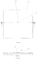
- Figures 1a is a top view of a section of a pipe 10 covered with a membrane 12 and a defect 14 shown in the membrane 12.
- Figure 1b is a sectional side view of the membrane coated pipe 10 of Figure 1a showing the defect 14.
- Figure 2 is a top view of a section of pipe 10 covered with the membrane 12 and a defect 14 shown in the membrane 12 covered by a temporary visual marker 16.
- the temporary visual markers may be brightly colored to be easily seen.
- the markers 16 may be applied as each defect 14 is identified along a section of pipe, and after the detection process is completed the workers may return to each site containing a marker 16 which is then removed and the repair device is applied as will be discussed below.
- a repair device for membranes coating metal pipes and metal storage tanks is shown mounted on a membrane 12 in the open position and partially disassembled.
- the repair device includes a patch member 30 having top and bottom surfaces, a protective outer wrap 32 having an inner bottom surface and an outer bottom surface.
- the protective outer wrap 32 includes a recessed portion having a size and shape to receive therein the patch member 30 such that the top surface of the patch member 30 is in physical contact with the inner bottom surface of the recessed portion.
- the device includes a removable protective film 28 applied to the bottom surface of the patch member 30.
- the device further includes a patch applicator 20 which in turn includes a support member or open frame 22 having a top surface, bottom surface with the support member defining an aperture 40 extending therethrough and an adhesive layer coated on said bottom surface and a removable protective film 38 applied over the adhesive layer.
- aperture 40 is shown as being a circular aperture as formed by support member 22 but it will be appreciated that support member 22 need not be circular, it could be partially circular or it could be any other shape, as long as the aperture is large enough so that the patch 30 can be pressed down onto the membrane within the open frame defined by frame 22.
- the device includes an arm 24 having first and second end portions, the first end portion is hingedly or pivotally attached to the top surface of the support member 22 and pivotally movable between a closed position ( Figure 4a ) and an open position ( Figure 5 ).
- the outer bottom surface of the protective outer wrap member 32 is detachably attached to a bottom surface of the second end portion of the arm 24.
- the arm 24 has a length selected such that when in the closed position the patch member 30 is generally centrally located in the aperture 40. It will be appreciated that while in the Figures the end portion of arm 24 to which patch 30 is releasibly attached is not exactly the same size as patch 30, it may be constructed to be the same size, or it may be different.
- the size and shape of the patch member 30 is not restricted to being disc shaped, they may be square, rectangular depending on the circumstances.
- the patch kit may be produced to applying elongate rectangular patches to membranes such as in cases where a membrane has a split or elongate crack.
- the applicator may be configured and shaped to be longer than its width.
- the protective outer wrap 32 is rigid or a flexible tape and the recessed portion defines a circumferentially disposed side wall 42 extending outwardly away from the inner bottom surface 44 to provide a side wall chamfered transition between the inner bottom surface 44 and an outer peripheral circumferentially disposed side wall section 46 that is substantially parallel to the inner bottom surface 44.
- the outer peripheral circumferentially disposed side wall section being coplanar with the bottom surface of the patch member 30 which is contact with the top of membrane 12, and has an adhesive located thereon for bonding the side wall section 46 to said membrane 12.
- the chamfered transition of the side wall 42 may have an angle of about 45° with respect to the inner bottom surface 44 of the protective outer wrap 32. This angled or chamfered outer wrap helps to protect patch 30 once the pipe has been buried in the event earth moves over the patch 30 and protective outer wrap 32 as the angle will help deflect the earth passing over it much better than a wrap not having a chamfered transition.
- the patch member 30 may have a complimentary shape matched to the recessed portion with of protective outer wrap 32 so that the chamfered transition of side wall 42 is completely filled by the patch member 30.
- the kit may include unique identifier permanently 26 affixed to either the top of the protective outer wrap 32 or it may be sandwiched between the inner bottom surface 44 of wrap 32 and the top surface of patch member 30, see Figure 4c .
- the unique identifier 26 may be a barcode, or it may be a radio frequency identification device (RFID).
- the patch member may be made of a conforming material such that upon application of the patch member 30 by the patch applicator 20 to the defect 14 in the membrane 12, the conforming material fills a void produced by the defect 14.
- the patch member 30 may be made of a polymeric material, such as, but not limited to, polyethylene, polypropylene, polyvinylchloride (PVC) and polycarbonate.
- the patch member 30 may be made from flexible non-curing materials, multi component resins (curing or non-curing) urethanes, polymers or other materials to mention a few non-limiting examples.
- the user then applies the patch applicator 20 to the defect by removing protective film 38 is removed from the bottom surface of the support member 22 thus exposing the adhesive layer on the bottom of support member 22 and the latter is temporarily bonded on the membrane 12 of the pipe 10 such that defect 14 in the membrane 12 is generally centrally located within the aperture 40 defined by support member 22.
- the arm 24 is pivoted to the open position and the removable protective film 28 applied to the bottom surface of the patch member 30 is removed when the arm 24 to expose the bottom surface of the patch member 30.
- Arm 24 is then pivoted to the closed position such that the bottom surface of the patch member 30 covers the defect 14 and the person applying the patch ensures the patch member 30 is pressed into the defect.
- the patch member 30, when made of a conforming adhesive material will partially or totally fill the void defined by the defect 14 and bond to membrane 12.
- the person applying the patch then detaches the protective outer wrap 32 from the bottom surface of the arm 24 and the patch applicator 20 is detached from the membrane 12 to leave behind patch member 30 on the membrane 12 which in turn is covered by the protective outer wrap 32.
- the process is repeated with all defect sites until the given section of pipe has been treated.
- the device disclosed in Figures 1 to 6b may be provided in the form of a kit including the patch member and the applicator provided as separate components forming the kit.
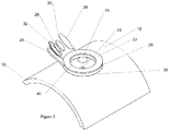
- Figure 7 shows a perspective view of another embodiment of a repair device for repairing a membrane defect shown generally at 50 with the device shown on a membrane coat 60 on a pipe 61 during the operation of repairing the membrane 60.
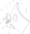
- Figure 8 shows a perspective view of the repair device 50 with the device shown in the open position while coupled to the top surface of the membrane 60.
- Repair device 50 includes ring 62 that may be made of a rigid polymer material. Ring 62 is preferably produced having a curvature of similar radius matching that of the pipe 61.
- a repair kit may be produced for repairing different diameter pipes. Typical standard pipes include 10", 16", 24" etc. diameter pipes so that a repair kit could include multiple repair devices with a set number included for a given diameter of pipe.
- Curved annular ring 62 includes a tab 63 integrally formed therewith which is useful for a user to remove device 50 from the membrane once the patch operation has been completed.
- a mould portion (also referred to as a lid) 64 of device 50 is connected to ring 62 by way of a living hinge 70 or other hinge design so that lid portion 64 can be moved from a closed position, see Figure 7 , to an open position, see Figure 8 .
- mould portion 64 has a centrally disposed hole 76 extending through it which has a diameter sufficient to receive the leading end of a syringe tube 66, Shown in Figures 7 , 9 , 10a and 10b .
- Lid portion 64 also includes several vent and witness holes 78 disposed around the circular periphery of the mould section 64.
- the repair device 50 is placed on the membrane 60 with annular ring 62 positioned around the temporary visual indicators 16 covering defect 72 with the defect located approximately in the center of the ring 62.
- Defects 72 may be a hole, a partial tear etc., in the membrane, with such defects typically being referred to as a "holiday".
- repair device 50 includes a ring 62 adhesive connector foam 68 which is an annular ring of the same diameter as ring 62 which has adhesive on both sides so that the ring 62 can be temporarily bonded to the top surface of membrane 60.
- the inner surface of mould section 64 has a peripheral raised shoulder such that when section 64 is moved to the closed position, a chamber is produced between the top of the membrane 60 and mould section 64 which will be filled with the sealing epoxy.
- repair device 50 includes a mould adhesive connector foam 74 located on the raised peripheral shoulder and which has adhesive on both sides so that the mould portion 64 can be temporarily bonded to the top surface of membrane 60 located on pipe 61 when in the closed position.
- Figure 10b shows a cross sectional view taken along the line A-A of Figure 10a as can be seen when repair device 50 is mounted on membrane 60 the radius of curvature of ring 62 exactly matches the curvature of the pipe 61 so there are no gaps between ring 62 and membrane 60.
- the holiday defects in a given length of pipe are first detected, and a temporary identification patch with a light adhesive is placed over the defect, the patch being brightly colored in one example for easy visual detection.
- the user removes the protective sheet on the bottom of ring 62 adhesive connector foam 68, centers device 50 over the defect 72 (after the temporary identification patch has been removed) with the defect in the center of ring 62 and presses down to temporarily bond ring 62 to the top of the membrane surface 60.
- mould portion 64 is pivoted from the open position ( Figure 10b ) to the closed position ( Figure 7 ) whereby the bottom surface of adhesive connector foam 74 bonds mould portion 64 to the top surface of membrane 60, thereby forming a seal.
- the syringe 66 filled with epoxy, is inserted with its leading tip into hole 76 in mould portion 64.
- the user then activates the plunger in syringe 66 to inject the epoxy into the chamber defined between the closed mould section 64 and the top surface of membrane 60 encircled by ring 62 at the center of which is defect 72.
- any excess epoxy will flow out through the holes 78 which will inform the user that the chamber is filled with epoxy and no more is needed. It is noted that when injecting the liquid into the chamber air will be expelled through holes 78 as it is being filled with the liquid to prevent air bubbles being formed in the patch.
- the epoxy is allowed to set for a few minutes and once it is set the user can remove the entire repair device 50 from the top surface of membrane 60 by prying up on tab 63 thereby releasing adhesive rings 68 and 74 from membrane 60.
- Figures 10c and 10d show a particular embodiment of the repair device 50 wherein the patch member includes a rubber O-ring 84 affixed to the peripheral edge of lid 64 which replaces ring 74 in Figure 10b and may be made from a variation of materials including but not limited to rubber, silicon, polyethylene and neoprene.
- the lid 64 bonds to adhesive ring 82 and the O-ring forms a seal that will prevent any liquid from flowing out of the enclosed chamber.
- the adhesive ring 82 could be either where it is shown in Figure 10C on the outer ring 62, or on the lid 64 on the outside of the peripheral edge, or the recessed edge.
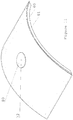
- Figure 11 shows the patched membrane 60 after remove of the repair device 50 leaving behind the patch 80 covering the defect 72.
- the material from which patch 80 is made may be made of any one or combination of epoxies, urethanes, ultra-violet curing compounds or other resinous materials.
- the device disclosed and illustrated in Figures 7 to 11 may be provided in the form of a kit including the syringe holding the liquid precursor of the sealant material and the applicator being provided as separate components forming the kit.
Landscapes
- Engineering & Computer Science (AREA)
- General Engineering & Computer Science (AREA)
- Mechanical Engineering (AREA)
- Pipe Accessories (AREA)
Claims (15)
- Vorrichtung zum Reparieren von Membranen, die Metallrohre und Lagertanks aus Metall beschichten, umfassend:a) ein Flickenelement (30) mit einer oberen und einer unteren Oberfläche, eine äußere Schutzhülle (32) mit einer inneren unteren Oberfläche und einer äußeren unteren Oberfläche, wobei die äußere Schutzhülle (32) einen zurückgesetzten Abschnitt mit einer Größe und einer Form aufweist, durch die sie das Flickenelement (30) so aufnehmen kann, dass die obere Oberfläche des Flickenelements mit der inneren unteren Oberfläche des zurückgesetzten Abschnitts in physischem Kontakt steht, eine ablösbare Schutzfolie, die auf die untere Oberfläche des Flickenelements (30) aufgebracht ist;b) einen Flickenapplikator (20) miti) einem Trägerelement (22) mit einer oberen Oberfläche, einer unteren Oberfläche, einer dort hindurch verlaufenden Öffnung (40) und einer die untere Oberfläche beschichtenden Klebstoffschicht und einer ablösbaren Schutzfolie (28), die über dem Klebstoff aufgebracht ist;ii) einen Arm (24) mit einem ersten und einem zweiten Endabschnitt, wobei der erste Endabschnitt gelenkig an der oberen Oberfläche des Trägerelements befestigt ist und durch Verschwenken zwischen einer geschlossenen Position und einer offenen Position bewegbar ist, wobei die äußere untere Oberfläche des Elements, das die äußere Schutzhülle (32) bildet, lösbar an einer unteren Oberfläche des zweiten Endabschnitts des Armes befestigt ist, wobei der Arm eine Länge aufweist, die so ausgewählt ist, dass das Flickenelement (30), wenn die geschlossene Position eingenommen wird, allgemein mittig in der Öffnung (40) liegt; undc) wobei die untere Oberfläche des Trägerelements (22) im Gebrauch vorübergehend so an eine Membran eines Rohres (61) oder Lagertanks gebunden wird, dass ein Defekt (72) in der Membran allgemein mittig in der Öffnung liegt. wobei die lösbare Schutzfolie (28), die auf die untere Oberfläche des Flickenelements aufgebracht ist, entfernt wird, wenn der Arm (24) die offene Position einnimmt, um die untere Oberfläche des Flickenelements (30) freizulegen, und der Arm in die geschlossene Position geschwenkt wird, so dass die untere Oberfläche des Flickenelements den Defekt (72) abdeckt, und die äußere Schutzhülle (32) von der unteren Oberfläche des Armes gelöst wird und der Flickenapplikator (20) von der Membran abgenommen wird, um das Flickenelement auf der Membran zurückzulassen, die von der äußeren Schutzhülle bedeckt wird.
- Vorrichtung nach Anspruch 1, wobei die äußere Schutzhülle (32) starr ist und der zurückgesetzte Abschnitt eine ringsum angeordnete Seitenwand definiert, die sich weg von der inneren unteren Oberfläche nach außen erstreckt, um einen abgeschrägten Übergang der Seitenwand (42) zwischen der inneren unteren Oberfläche (44) und einem äußeren Randabschnitt (46) der ringsum angeordneten Seitenwand, der im Wesentlichen parallel ist zu der inneren unteren Oberfläche, bereitzustellen, wobei der äußere Randabschnitt der ringsum angeordneten Seitenwand komplanar ist mit der unteren Oberfläche des Flickenelements und mit Klebstoff beschichtet ist, um ihn an die Membran zu binden.
- Vorrichtung nach Anspruch 2, wobei das Flickenelement (30) eine komplementäre Form aufweist, die zu dem zurückgesetzten Abschnitt mit dem abgeschrägten Übergang der Seitenwand passt, so dass der zurückgesetzte Abschnitt vollständig von dem Flickenelement ausgefüllt wird.
- Vorrichtung nach Anspruch 1, 2 oder 3, einen temporären, entfernbaren Indikatorflicken zur Aufbringung auf eine defekte Stelle an der Membran einschließend, um die defekte Stelle visuell zu markieren, bevor der Flickenapplikator temporär an die Membran gebunden wird.
- Vorrichtung nach einem der Ansprüche 1 bis 4, eine eindeutige Kennung aufweisend, die permanent an der äußeren Schutzhülle (32) fixiert ist, wobei die eindeutige Kennung (26) optional ein Barcode oder eine Funkfrequenzidentifikationsvorrichtung (RFID) ist.
- Vorrichtung nach einem der Ansprüche 1 bis 5, wobei das Flickenelement (30) aus einem sich anpassenden Material gebildet ist, so dass bei der Aufbringung des Flickenelements auf den Defekt der Membran mit dem Flickenapplikator (20) das sich anpassende Material die von dem Defekt gebildete Leerstelle ausfüllt.
- Vorrichtung nach einem der Ansprüche 1 bis 6, wobei das Flickenelement (30) aus einem polymeren Material, vorzugsweise Polyethylen, Polypropylen, Polyvinylchlorid (PVC) oder Polycarbonat, gebildet ist oder das Flickenelement (30) aus flexiblen, nicht-härtenden Materialien, Multikomponentenharzen (härtend oder nicht-härtend) Urethanen gebildet ist.
- Vorrichtung nach einem der Ansprüche 1 bis 7 in Form eines Kits, welches das Flickenelement (30) und den Applikator als separate Komponenten, die das Kit bilden, einschließt.
- Vorrichtung (50) zum Reparieren von Membranen, die Metallrohre und Lagertanks aus Metall beschichten, umfassend:a) eine Spritze (66) zum Halten einer flüssigen Vorstufe eines Dichtungsmaterials;b) einen Applikator miti) einem Trägerelement, das eine obere Oberfläche, eine untere Oberfläche, eine dort hindurch verlaufende Öffnung und eine erste Klebstoffschicht, mit der die untere Oberfläche beschichtet ist, aufweist;ii) einen Deckelabschnitt (64), der einen ersten und einen zweiten Endabschnitt aufweist, wobei der erste Endabschnitt gelenkig an dem Trägerelement befestigt ist und durch Verschwenken zwischen einer geschlossenen Position und einer offenen Position bewegbar ist, wobei der Deckelabschnitt eine innere Oberfläche mit einer erhabenen Randschulter und eine zweite Klebstoffschicht, mit der die erhabene Randschulter beschichtet ist, aufweist, wobei der Deckelabschnitt eine Öffnung (40), die sich dort hindurch erstreckt, um eine Austrittsspitze der Spritze (66) aufzunehmen, und eine Mehrzahl von um den Rand des Deckelabschnitts herum angeordneten, an die erhabene Randschulter angrenzenden Auslassöffnungen (78) aufweist; undd) wobei das Trägerelement im Betrieb über einem Defekt in einer Membran positioniert wird, wobei der Defekt allgemein in der Öffnung zentriert wird, wobei das Trägerelement in die Membran gedrückt wird, um es über die erste Klebstoffschicht temporär an die Membran zu binden, und wobei der Deckelabschnitt in die geschlossene Position geschwenkt und auf die obere Oberfläche des Trägerelements gedrückt wird, um ihn über die zweite Klebstoffschicht temporär an eine Oberseite der Membran zu binden, und wobei die Austrittsspitze der Spritze (66) in die Öffnung eingeführt wird und die flüssige Vorstufe in einen Raum eingespritzt wird, der zwischen der Membran und einer Innenfläche des Deckelabschnitts definiert wird, und sobald die flüssige Vorstufe durch die Auslassöffnungen aus dem Raum austritt, die Einspritzung von weiterer flüssiger Vorstufe beendet wird und die flüssige Vorstufe in eine feste Form härten gelassen wird, und anschließend das Reparatur-Kit unter Zurücklassung eines geflickten Defekts entfernt wird.
- Vorrichtung (50) nach Anspruch 9, wobei der Deckelabschnitt (64) und das Trägerelement aus einem Polymer- oder Kunststoffmaterial gebildet sind, und wobei der Deckelabschnitt (64) über ein Biegescharnier (70) gelenkig an dem Trägerelement befestigt ist.
- Vorrichtung (50) nach Anspruch 9 oder 10, wobei das Dichtungsmaterial irgendeines oder eine Kombination ist von Epoxiden, Urethanen, durch Ultraviolettlicht härtenden Verbindungen oder anderen harzartigen Materialien.
- Vorrichtung (50) nach einem der Ansprüche 9 bis 11, wobei die innere Oberfläche des Deckelabschnitts einen O-Ring aufweist, der in die innere Oberfläche integriert ist und der auf einer Außenseite der erhabenen Randschulter am Rand angeordnet ist, um zu verhindern, dass Flüssigkeit aus der Kammer gelangt.
- Vorrichtung (50) nach einem der Ansprüche 9 bis 11, wobei die innere Oberfläche des Deckelabschnitts einen O-Ring aufweist, der in die innere Oberfläche integriert ist und der auf einer Innenseite der erhabenen Randschulter am Rand angeordnet ist, um zu verhindern, dass Flüssigkeit aus der Kammer gelangt.
- Vorrichtung (50) nach den Ansprüchen 12 oder 13, wobei der O-Ring aus irgendeinem von Kautschuk, Silicium, Polyethylen und Neopren gebildet ist.
- Vorrichtung (50) nach einem der Ansprüche 9 bis 14 in Form eines Kits, das die Spritze (66), welche die flüssige Vorstufe des Dichtungsmaterials enthält, und den Applikator als separate Komponenten, die das Kit bilden, enthält.
Applications Claiming Priority (3)
| Application Number | Priority Date | Filing Date | Title |
|---|---|---|---|
| US201562186658P | 2015-06-30 | 2015-06-30 | |
| US201562266307P | 2015-12-11 | 2015-12-11 | |
| PCT/CA2016/050756 WO2017000066A1 (en) | 2015-06-30 | 2016-06-27 | Coating/membrane repair kit |
Publications (4)
| Publication Number | Publication Date |
|---|---|
| EP3347640A1 EP3347640A1 (de) | 2018-07-18 |
| EP3347640A4 EP3347640A4 (de) | 2019-05-15 |
| EP3347640B1 true EP3347640B1 (de) | 2020-10-07 |
| EP3347640B8 EP3347640B8 (de) | 2020-12-09 |
Family
ID=57607428
Family Applications (1)
| Application Number | Title | Priority Date | Filing Date |
|---|---|---|---|
| EP16816884.7A Not-in-force EP3347640B8 (de) | 2015-06-30 | 2016-06-27 | Beschichtungs-/membranreparaturkit |
Country Status (4)
| Country | Link |
|---|---|
| US (1) | US10386007B2 (de) |
| EP (1) | EP3347640B8 (de) |
| CA (1) | CA2989198A1 (de) |
| WO (1) | WO2017000066A1 (de) |
Families Citing this family (4)
| Publication number | Priority date | Publication date | Assignee | Title |
|---|---|---|---|---|
| WO2021195271A1 (en) * | 2020-03-24 | 2021-09-30 | Elcometer Inc. | Coating repair kit and method of repairing a pipe |
| US11767943B2 (en) * | 2020-12-10 | 2023-09-26 | Xcel Energy | Vent box method and appartus |
| US11199287B1 (en) * | 2021-02-23 | 2021-12-14 | Trinity Bay Equipment Holdings, LLC | Multi-layer pipe tubing repair systems and methods |
| KR102736383B1 (ko) * | 2022-09-19 | 2024-11-28 | 한국수력원자력 주식회사 | 원자력 발전소 해수배관 관리장치 및 관리방법 |
Family Cites Families (13)
| Publication number | Priority date | Publication date | Assignee | Title |
|---|---|---|---|---|
| US1662852A (en) * | 1925-05-05 | 1928-03-20 | Percy F Mckendrick | Repairing pipe |
| GB1546073A (en) * | 1976-05-10 | 1979-05-16 | Ready Seal Ltd | Method of repairing leaks in pipes and pipelines carrying fluent medium under pressure and means for use in the method |
| US4497418A (en) * | 1984-02-15 | 1985-02-05 | Kennecott Corporation | Repair plug assembly for vessel having a corrosion resistant lining |
| KR890002508A (ko) | 1987-07-03 | 1989-04-10 | 고니시 신이찌로오 | 콘크리트 구조물의 균열부위 접착제 주입방법 |
| DE8806284U1 (de) * | 1988-05-11 | 1989-09-14 | Espe Stiftung & Co Produktions- und Vertriebs KG, 8031 Seefeld | Vorrichtung zum Ausbessern von Steinschlagschäden an Windschutzscheiben |
| MX9300808A (es) * | 1992-02-18 | 1993-09-01 | Pfaudler Co Inc | Mejoras en metodo y conujunto de tapon para reparacion por compresion. |
| US5301983A (en) * | 1992-03-23 | 1994-04-12 | Porowski Jan S | Pipe component seal assembly |
| US5423932A (en) * | 1993-12-02 | 1995-06-13 | American Velodur Metal, Inc. | Apparatus for sealing leaks |
| US5711639A (en) * | 1996-02-01 | 1998-01-27 | Emerson & Cuming Composite Materials, Inc. | Clamp for cylindrical object |
| US6013343A (en) * | 1997-09-15 | 2000-01-11 | Radke; Edgar Helge Fred | Patch for fabric air tubes |
| US6685784B1 (en) * | 1998-10-30 | 2004-02-03 | Gerald Jacino | Glass break repair kit apparatus and method |
| DE202013004368U1 (de) * | 2013-04-02 | 2013-06-25 | Frank Blienert | Dichtverfahren für Gasaussenabdichtungen |
| US9095736B2 (en) * | 2013-05-07 | 2015-08-04 | Engineered Corrosion Solutions, Llc | Corrosion monitoring in a fire sprinkler system |
-
2016
- 2016-06-27 EP EP16816884.7A patent/EP3347640B8/de not_active Not-in-force
- 2016-06-27 WO PCT/CA2016/050756 patent/WO2017000066A1/en not_active Ceased
- 2016-06-27 CA CA2989198A patent/CA2989198A1/en not_active Abandoned
- 2016-06-27 US US15/738,684 patent/US10386007B2/en active Active
Non-Patent Citations (1)
| Title |
|---|
| None * |
Also Published As
| Publication number | Publication date |
|---|---|
| WO2017000066A1 (en) | 2017-01-05 |
| EP3347640B8 (de) | 2020-12-09 |
| CA2989198A1 (en) | 2017-01-05 |
| US20180187818A1 (en) | 2018-07-05 |
| US10386007B2 (en) | 2019-08-20 |
| EP3347640A1 (de) | 2018-07-18 |
| EP3347640A4 (de) | 2019-05-15 |
Similar Documents
| Publication | Publication Date | Title |
|---|---|---|
| EP3347640B1 (de) | Beschichtungs-/membranreparaturkit | |
| EP2185854B1 (de) | Verfahren zur rohrreparatur | |
| JPH10503134A (ja) | 支持フォームを使用することなく構造物を表面処理または修復する方法 | |
| CA2150111A1 (en) | Improvements relating to the lining of pipelines and passageways | |
| US20110197413A1 (en) | Method and apparatus for lining a pipe | |
| RU2134835C1 (ru) | Способ герметизации места утечки в содержащем текучую среду теле, средство и накладка для герметизации места утечки и аппликатор для крепления накладки | |
| AU2019334801C1 (en) | Double skin structure with interstitial spacer | |
| EP1137536B1 (de) | Auskleidung für tanks | |
| KR101917296B1 (ko) | 파손 배관 보수 방법 | |
| JP6120681B2 (ja) | 既設管路の補修部材およびそれを備えた地下排水施設 | |
| KR20070119688A (ko) | 페인트 및 실런트를 제거하기 위한 방법 및 장치 | |
| RU2341721C1 (ru) | Способ проведения ремонтных работ на трубопроводе с использованием временного перекрытия (варианты) и тампон-герметизатор для временного перекрытия трубопровода | |
| JP2641713B2 (ja) | マンホール補修方法並びに閉塞材、マンホール補修材及び拡径具 | |
| US20120324850A1 (en) | Air Filter Element with Covered Terminal Disks | |
| JP6471043B2 (ja) | 筒部の補修部材、それを備えた地下排水施設、および筒部の補修方法 | |
| KR100442005B1 (ko) | Frp 판을 이용한 주유소 기름 탱크의 이중 외피 | |
| EP4397823B1 (de) | Harzinjektionssystem, wasserabdichtungsprodukt und verwendungsverfahren | |
| JP4056078B1 (ja) | 気体・液体のリーク止め方法 | |
| JP6558886B2 (ja) | 屋外設備損傷部補修構造及び屋外設備損傷部補修方法 | |
| EP4127551A1 (de) | Beschichtungsreparaturkit und verfahren zur reparatur eines rohrs | |
| US20180085779A1 (en) | Submerged coating repair of potable water systems | |
| US20110006483A1 (en) | Form in place gasket membrane | |
| JP6727963B2 (ja) | 封止工法 | |
| US20200386360A1 (en) | Saturation systems and methods for pipeline and pressure vessel repair | |
| IES20000542A2 (en) | Tank lining |
Legal Events
| Date | Code | Title | Description |
|---|---|---|---|
| STAA | Information on the status of an ep patent application or granted ep patent |
Free format text: STATUS: THE INTERNATIONAL PUBLICATION HAS BEEN MADE |
|
| PUAI | Public reference made under article 153(3) epc to a published international application that has entered the european phase |
Free format text: ORIGINAL CODE: 0009012 |
|
| STAA | Information on the status of an ep patent application or granted ep patent |
Free format text: STATUS: REQUEST FOR EXAMINATION WAS MADE |
|
| 17P | Request for examination filed |
Effective date: 20180508 |
|
| AK | Designated contracting states |
Kind code of ref document: A1 Designated state(s): AL AT BE BG CH CY CZ DE DK EE ES FI FR GB GR HR HU IE IS IT LI LT LU LV MC MK MT NL NO PL PT RO RS SE SI SK SM TR |
|
| AX | Request for extension of the european patent |
Extension state: BA ME |
|
| DAV | Request for validation of the european patent (deleted) | ||
| DAX | Request for extension of the european patent (deleted) | ||
| RIC1 | Information provided on ipc code assigned before grant |
Ipc: F16L 55/168 20060101ALI20190206BHEP Ipc: F16L 55/18 20060101AFI20190206BHEP |
|
| RIC1 | Information provided on ipc code assigned before grant |
Ipc: F16L 55/168 20060101ALI20190212BHEP Ipc: F16L 55/18 20060101AFI20190212BHEP |
|
| RIC1 | Information provided on ipc code assigned before grant |
Ipc: F16L 55/168 20060101ALI20190227BHEP Ipc: F16L 55/18 20060101AFI20190227BHEP |
|
| RIC1 | Information provided on ipc code assigned before grant |
Ipc: F16L 55/18 20060101AFI20190327BHEP Ipc: F16L 55/168 20060101ALI20190327BHEP |
|
| RIC1 | Information provided on ipc code assigned before grant |
Ipc: F16L 55/18 20060101AFI20190402BHEP Ipc: F16L 55/168 20060101ALI20190402BHEP |
|
| A4 | Supplementary search report drawn up and despatched |
Effective date: 20190415 |
|
| RIC1 | Information provided on ipc code assigned before grant |
Ipc: F16L 55/168 20060101ALI20200211BHEP Ipc: F16L 55/18 20060101AFI20200211BHEP |
|
| REG | Reference to a national code |
Ref country code: DE Ref legal event code: R079 Ref document number: 602016045497 Country of ref document: DE Free format text: PREVIOUS MAIN CLASS: F16L0055180000 Ipc: F17D0005020000 |
|
| GRAP | Despatch of communication of intention to grant a patent |
Free format text: ORIGINAL CODE: EPIDOSNIGR1 |
|
| STAA | Information on the status of an ep patent application or granted ep patent |
Free format text: STATUS: GRANT OF PATENT IS INTENDED |
|
| RIC1 | Information provided on ipc code assigned before grant |
Ipc: F16L 55/18 20060101ALI20200325BHEP Ipc: F17D 5/02 20060101AFI20200325BHEP Ipc: F17C 1/00 20060101ALI20200325BHEP Ipc: F16L 55/168 20060101ALI20200325BHEP |
|
| INTG | Intention to grant announced |
Effective date: 20200420 |
|
| RIN1 | Information on inventor provided before grant (corrected) |
Inventor name: MITCHELL, JACK A. |
|
| RAP1 | Party data changed (applicant data changed or rights of an application transferred) |
Owner name: PRO PAINT GEAR INC. |
|
| RIN1 | Information on inventor provided before grant (corrected) |
Inventor name: MITCHELL, JACK A. |
|
| GRAS | Grant fee paid |
Free format text: ORIGINAL CODE: EPIDOSNIGR3 |
|
| GRAA | (expected) grant |
Free format text: ORIGINAL CODE: 0009210 |
|
| STAA | Information on the status of an ep patent application or granted ep patent |
Free format text: STATUS: THE PATENT HAS BEEN GRANTED |
|
| AK | Designated contracting states |
Kind code of ref document: B1 Designated state(s): AL AT BE BG CH CY CZ DE DK EE ES FI FR GB GR HR HU IE IS IT LI LT LU LV MC MK MT NL NO PL PT RO RS SE SI SK SM TR |
|
| REG | Reference to a national code |
Ref country code: GB Ref legal event code: FG4D |
|
| REG | Reference to a national code |
Ref country code: CH Ref legal event code: EP Ref country code: AT Ref legal event code: REF Ref document number: 1321512 Country of ref document: AT Kind code of ref document: T Effective date: 20201015 |
|
| REG | Reference to a national code |
Ref country code: DE Ref legal event code: R096 Ref document number: 602016045497 Country of ref document: DE |
|
| REG | Reference to a national code |
Ref country code: DE Ref legal event code: R081 Ref document number: 602016045497 Country of ref document: DE Owner name: ELCOMETER LIMITED, MANCHESTER, GB Free format text: FORMER OWNER: PRO PAINT GEAR INC., BRIGHTON, CA Ref country code: IE Ref legal event code: FG4D |
|
| RAP2 | Party data changed (patent owner data changed or rights of a patent transferred) |
Owner name: ELCOMETER, INC. |
|
| REG | Reference to a national code |
Ref country code: CH Ref legal event code: PK Free format text: BERICHTIGUNG B8 |
|
| REG | Reference to a national code |
Ref country code: NL Ref legal event code: MP Effective date: 20201007 |
|
| REG | Reference to a national code |
Ref country code: AT Ref legal event code: MK05 Ref document number: 1321512 Country of ref document: AT Kind code of ref document: T Effective date: 20201007 |
|
| PG25 | Lapsed in a contracting state [announced via postgrant information from national office to epo] |
Ref country code: GR Free format text: LAPSE BECAUSE OF FAILURE TO SUBMIT A TRANSLATION OF THE DESCRIPTION OR TO PAY THE FEE WITHIN THE PRESCRIBED TIME-LIMIT Effective date: 20210108 Ref country code: FI Free format text: LAPSE BECAUSE OF FAILURE TO SUBMIT A TRANSLATION OF THE DESCRIPTION OR TO PAY THE FEE WITHIN THE PRESCRIBED TIME-LIMIT Effective date: 20201007 Ref country code: NO Free format text: LAPSE BECAUSE OF FAILURE TO SUBMIT A TRANSLATION OF THE DESCRIPTION OR TO PAY THE FEE WITHIN THE PRESCRIBED TIME-LIMIT Effective date: 20210107 Ref country code: RS Free format text: LAPSE BECAUSE OF FAILURE TO SUBMIT A TRANSLATION OF THE DESCRIPTION OR TO PAY THE FEE WITHIN THE PRESCRIBED TIME-LIMIT Effective date: 20201007 Ref country code: PT Free format text: LAPSE BECAUSE OF FAILURE TO SUBMIT A TRANSLATION OF THE DESCRIPTION OR TO PAY THE FEE WITHIN THE PRESCRIBED TIME-LIMIT Effective date: 20210208 |
|
| REG | Reference to a national code |
Ref country code: LT Ref legal event code: MG4D |
|
| PG25 | Lapsed in a contracting state [announced via postgrant information from national office to epo] |
Ref country code: SE Free format text: LAPSE BECAUSE OF FAILURE TO SUBMIT A TRANSLATION OF THE DESCRIPTION OR TO PAY THE FEE WITHIN THE PRESCRIBED TIME-LIMIT Effective date: 20201007 Ref country code: AT Free format text: LAPSE BECAUSE OF FAILURE TO SUBMIT A TRANSLATION OF THE DESCRIPTION OR TO PAY THE FEE WITHIN THE PRESCRIBED TIME-LIMIT Effective date: 20201007 Ref country code: ES Free format text: LAPSE BECAUSE OF FAILURE TO SUBMIT A TRANSLATION OF THE DESCRIPTION OR TO PAY THE FEE WITHIN THE PRESCRIBED TIME-LIMIT Effective date: 20201007 Ref country code: PL Free format text: LAPSE BECAUSE OF FAILURE TO SUBMIT A TRANSLATION OF THE DESCRIPTION OR TO PAY THE FEE WITHIN THE PRESCRIBED TIME-LIMIT Effective date: 20201007 Ref country code: LV Free format text: LAPSE BECAUSE OF FAILURE TO SUBMIT A TRANSLATION OF THE DESCRIPTION OR TO PAY THE FEE WITHIN THE PRESCRIBED TIME-LIMIT Effective date: 20201007 Ref country code: IS Free format text: LAPSE BECAUSE OF FAILURE TO SUBMIT A TRANSLATION OF THE DESCRIPTION OR TO PAY THE FEE WITHIN THE PRESCRIBED TIME-LIMIT Effective date: 20210207 Ref country code: BG Free format text: LAPSE BECAUSE OF FAILURE TO SUBMIT A TRANSLATION OF THE DESCRIPTION OR TO PAY THE FEE WITHIN THE PRESCRIBED TIME-LIMIT Effective date: 20210107 |
|
| PG25 | Lapsed in a contracting state [announced via postgrant information from national office to epo] |
Ref country code: NL Free format text: LAPSE BECAUSE OF FAILURE TO SUBMIT A TRANSLATION OF THE DESCRIPTION OR TO PAY THE FEE WITHIN THE PRESCRIBED TIME-LIMIT Effective date: 20201007 Ref country code: HR Free format text: LAPSE BECAUSE OF FAILURE TO SUBMIT A TRANSLATION OF THE DESCRIPTION OR TO PAY THE FEE WITHIN THE PRESCRIBED TIME-LIMIT Effective date: 20201007 |
|
| REG | Reference to a national code |
Ref country code: DE Ref legal event code: R097 Ref document number: 602016045497 Country of ref document: DE |
|
| PG25 | Lapsed in a contracting state [announced via postgrant information from national office to epo] |
Ref country code: RO Free format text: LAPSE BECAUSE OF FAILURE TO SUBMIT A TRANSLATION OF THE DESCRIPTION OR TO PAY THE FEE WITHIN THE PRESCRIBED TIME-LIMIT Effective date: 20201007 Ref country code: SK Free format text: LAPSE BECAUSE OF FAILURE TO SUBMIT A TRANSLATION OF THE DESCRIPTION OR TO PAY THE FEE WITHIN THE PRESCRIBED TIME-LIMIT Effective date: 20201007 Ref country code: EE Free format text: LAPSE BECAUSE OF FAILURE TO SUBMIT A TRANSLATION OF THE DESCRIPTION OR TO PAY THE FEE WITHIN THE PRESCRIBED TIME-LIMIT Effective date: 20201007 Ref country code: CZ Free format text: LAPSE BECAUSE OF FAILURE TO SUBMIT A TRANSLATION OF THE DESCRIPTION OR TO PAY THE FEE WITHIN THE PRESCRIBED TIME-LIMIT Effective date: 20201007 Ref country code: LT Free format text: LAPSE BECAUSE OF FAILURE TO SUBMIT A TRANSLATION OF THE DESCRIPTION OR TO PAY THE FEE WITHIN THE PRESCRIBED TIME-LIMIT Effective date: 20201007 Ref country code: SM Free format text: LAPSE BECAUSE OF FAILURE TO SUBMIT A TRANSLATION OF THE DESCRIPTION OR TO PAY THE FEE WITHIN THE PRESCRIBED TIME-LIMIT Effective date: 20201007 |
|
| PLBE | No opposition filed within time limit |
Free format text: ORIGINAL CODE: 0009261 |
|
| STAA | Information on the status of an ep patent application or granted ep patent |
Free format text: STATUS: NO OPPOSITION FILED WITHIN TIME LIMIT |
|
| PG25 | Lapsed in a contracting state [announced via postgrant information from national office to epo] |
Ref country code: DK Free format text: LAPSE BECAUSE OF FAILURE TO SUBMIT A TRANSLATION OF THE DESCRIPTION OR TO PAY THE FEE WITHIN THE PRESCRIBED TIME-LIMIT Effective date: 20201007 |
|
| 26N | No opposition filed |
Effective date: 20210708 |
|
| PG25 | Lapsed in a contracting state [announced via postgrant information from national office to epo] |
Ref country code: AL Free format text: LAPSE BECAUSE OF FAILURE TO SUBMIT A TRANSLATION OF THE DESCRIPTION OR TO PAY THE FEE WITHIN THE PRESCRIBED TIME-LIMIT Effective date: 20201007 Ref country code: IT Free format text: LAPSE BECAUSE OF FAILURE TO SUBMIT A TRANSLATION OF THE DESCRIPTION OR TO PAY THE FEE WITHIN THE PRESCRIBED TIME-LIMIT Effective date: 20201007 |
|
| PG25 | Lapsed in a contracting state [announced via postgrant information from national office to epo] |
Ref country code: SI Free format text: LAPSE BECAUSE OF FAILURE TO SUBMIT A TRANSLATION OF THE DESCRIPTION OR TO PAY THE FEE WITHIN THE PRESCRIBED TIME-LIMIT Effective date: 20201007 |
|
| PG25 | Lapsed in a contracting state [announced via postgrant information from national office to epo] |
Ref country code: MC Free format text: LAPSE BECAUSE OF FAILURE TO SUBMIT A TRANSLATION OF THE DESCRIPTION OR TO PAY THE FEE WITHIN THE PRESCRIBED TIME-LIMIT Effective date: 20201007 |
|
| REG | Reference to a national code |
Ref country code: CH Ref legal event code: PL |
|
| REG | Reference to a national code |
Ref country code: BE Ref legal event code: MM Effective date: 20210630 |
|
| PG25 | Lapsed in a contracting state [announced via postgrant information from national office to epo] |
Ref country code: LU Free format text: LAPSE BECAUSE OF NON-PAYMENT OF DUE FEES Effective date: 20210627 |
|
| PG25 | Lapsed in a contracting state [announced via postgrant information from national office to epo] |
Ref country code: LI Free format text: LAPSE BECAUSE OF NON-PAYMENT OF DUE FEES Effective date: 20210630 Ref country code: IE Free format text: LAPSE BECAUSE OF NON-PAYMENT OF DUE FEES Effective date: 20210627 Ref country code: CH Free format text: LAPSE BECAUSE OF NON-PAYMENT OF DUE FEES Effective date: 20210630 |
|
| PG25 | Lapsed in a contracting state [announced via postgrant information from national office to epo] |
Ref country code: IS Free format text: LAPSE BECAUSE OF FAILURE TO SUBMIT A TRANSLATION OF THE DESCRIPTION OR TO PAY THE FEE WITHIN THE PRESCRIBED TIME-LIMIT Effective date: 20210207 |
|
| REG | Reference to a national code |
Ref country code: DE Ref legal event code: R081 Ref document number: 602016045497 Country of ref document: DE Owner name: ELCOMETER LIMITED, MANCHESTER, GB Free format text: FORMER OWNER: ELCOMETER, INC., WARREN, MI, US |
|
| REG | Reference to a national code |
Ref country code: GB Ref legal event code: 732E Free format text: REGISTERED BETWEEN 20220630 AND 20220706 |
|
| PG25 | Lapsed in a contracting state [announced via postgrant information from national office to epo] |
Ref country code: BE Free format text: LAPSE BECAUSE OF NON-PAYMENT OF DUE FEES Effective date: 20210630 |
|
| PG25 | Lapsed in a contracting state [announced via postgrant information from national office to epo] |
Ref country code: CY Free format text: LAPSE BECAUSE OF FAILURE TO SUBMIT A TRANSLATION OF THE DESCRIPTION OR TO PAY THE FEE WITHIN THE PRESCRIBED TIME-LIMIT Effective date: 20201007 |
|
| P01 | Opt-out of the competence of the unified patent court (upc) registered |
Effective date: 20230525 |
|
| PG25 | Lapsed in a contracting state [announced via postgrant information from national office to epo] |
Ref country code: HU Free format text: LAPSE BECAUSE OF FAILURE TO SUBMIT A TRANSLATION OF THE DESCRIPTION OR TO PAY THE FEE WITHIN THE PRESCRIBED TIME-LIMIT; INVALID AB INITIO Effective date: 20160627 |
|
| PGFP | Annual fee paid to national office [announced via postgrant information from national office to epo] |
Ref country code: FR Payment date: 20230503 Year of fee payment: 8 Ref country code: DE Payment date: 20230630 Year of fee payment: 8 |
|
| PGFP | Annual fee paid to national office [announced via postgrant information from national office to epo] |
Ref country code: GB Payment date: 20230503 Year of fee payment: 8 |
|
| PG25 | Lapsed in a contracting state [announced via postgrant information from national office to epo] |
Ref country code: MK Free format text: LAPSE BECAUSE OF FAILURE TO SUBMIT A TRANSLATION OF THE DESCRIPTION OR TO PAY THE FEE WITHIN THE PRESCRIBED TIME-LIMIT Effective date: 20201007 |
|
| PG25 | Lapsed in a contracting state [announced via postgrant information from national office to epo] |
Ref country code: MT Free format text: LAPSE BECAUSE OF FAILURE TO SUBMIT A TRANSLATION OF THE DESCRIPTION OR TO PAY THE FEE WITHIN THE PRESCRIBED TIME-LIMIT Effective date: 20201007 |
|
| REG | Reference to a national code |
Ref country code: DE Ref legal event code: R119 Ref document number: 602016045497 Country of ref document: DE |
|
| GBPC | Gb: european patent ceased through non-payment of renewal fee |
Effective date: 20240627 |
|
| PG25 | Lapsed in a contracting state [announced via postgrant information from national office to epo] |
Ref country code: DE Free format text: LAPSE BECAUSE OF NON-PAYMENT OF DUE FEES Effective date: 20250101 |
|
| PG25 | Lapsed in a contracting state [announced via postgrant information from national office to epo] |
Ref country code: FR Free format text: LAPSE BECAUSE OF NON-PAYMENT OF DUE FEES Effective date: 20240630 |
|
| PG25 | Lapsed in a contracting state [announced via postgrant information from national office to epo] |
Ref country code: GB Free format text: LAPSE BECAUSE OF NON-PAYMENT OF DUE FEES Effective date: 20240627 |
|
| PG25 | Lapsed in a contracting state [announced via postgrant information from national office to epo] |
Ref country code: TR Free format text: LAPSE BECAUSE OF FAILURE TO SUBMIT A TRANSLATION OF THE DESCRIPTION OR TO PAY THE FEE WITHIN THE PRESCRIBED TIME-LIMIT Effective date: 20201007 |