EP1137536B1 - Auskleidung für tanks - Google Patents
Auskleidung für tanks Download PDFInfo
- Publication number
- EP1137536B1 EP1137536B1 EP99956295A EP99956295A EP1137536B1 EP 1137536 B1 EP1137536 B1 EP 1137536B1 EP 99956295 A EP99956295 A EP 99956295A EP 99956295 A EP99956295 A EP 99956295A EP 1137536 B1 EP1137536 B1 EP 1137536B1
- Authority
- EP
- European Patent Office
- Prior art keywords
- tank
- grid
- grp
- interstitial
- lined
- Prior art date
- Legal status (The legal status is an assumption and is not a legal conclusion. Google has not performed a legal analysis and makes no representation as to the accuracy of the status listed.)
- Expired - Lifetime
Links
Images

Classifications
-
- B—PERFORMING OPERATIONS; TRANSPORTING
- B32—LAYERED PRODUCTS
- B32B—LAYERED PRODUCTS, i.e. PRODUCTS BUILT-UP OF STRATA OF FLAT OR NON-FLAT, e.g. CELLULAR OR HONEYCOMB, FORM
- B32B27/00—Layered products comprising a layer of synthetic resin
- B32B27/12—Layered products comprising a layer of synthetic resin next to a fibrous or filamentary layer
-
- B—PERFORMING OPERATIONS; TRANSPORTING
- B32—LAYERED PRODUCTS
- B32B—LAYERED PRODUCTS, i.e. PRODUCTS BUILT-UP OF STRATA OF FLAT OR NON-FLAT, e.g. CELLULAR OR HONEYCOMB, FORM
- B32B15/00—Layered products comprising a layer of metal
- B32B15/02—Layer formed of wires, e.g. mesh
-
- B—PERFORMING OPERATIONS; TRANSPORTING
- B65—CONVEYING; PACKING; STORING; HANDLING THIN OR FILAMENTARY MATERIAL
- B65D—CONTAINERS FOR STORAGE OR TRANSPORT OF ARTICLES OR MATERIALS, e.g. BAGS, BARRELS, BOTTLES, BOXES, CANS, CARTONS, CRATES, DRUMS, JARS, TANKS, HOPPERS, FORWARDING CONTAINERS; ACCESSORIES, CLOSURES, OR FITTINGS THEREFOR; PACKAGING ELEMENTS; PACKAGES
- B65D90/00—Component parts, details or accessories for large containers
- B65D90/02—Wall construction
- B65D90/028—Wall construction hollow-walled, e.g. double-walled with spacers
-
- B—PERFORMING OPERATIONS; TRANSPORTING
- B65—CONVEYING; PACKING; STORING; HANDLING THIN OR FILAMENTARY MATERIAL
- B65D—CONTAINERS FOR STORAGE OR TRANSPORT OF ARTICLES OR MATERIALS, e.g. BAGS, BARRELS, BOTTLES, BOXES, CANS, CARTONS, CRATES, DRUMS, JARS, TANKS, HOPPERS, FORWARDING CONTAINERS; ACCESSORIES, CLOSURES, OR FITTINGS THEREFOR; PACKAGING ELEMENTS; PACKAGES
- B65D90/00—Component parts, details or accessories for large containers
- B65D90/02—Wall construction
- B65D90/04—Linings
-
- B—PERFORMING OPERATIONS; TRANSPORTING
- B32—LAYERED PRODUCTS
- B32B—LAYERED PRODUCTS, i.e. PRODUCTS BUILT-UP OF STRATA OF FLAT OR NON-FLAT, e.g. CELLULAR OR HONEYCOMB, FORM
- B32B2262/00—Composition or structural features of fibres which form a fibrous or filamentary layer or are present as additives
- B32B2262/10—Inorganic fibres
- B32B2262/101—Glass fibres
-
- B—PERFORMING OPERATIONS; TRANSPORTING
- B32—LAYERED PRODUCTS
- B32B—LAYERED PRODUCTS, i.e. PRODUCTS BUILT-UP OF STRATA OF FLAT OR NON-FLAT, e.g. CELLULAR OR HONEYCOMB, FORM
- B32B2307/00—Properties of the layers or laminate
- B32B2307/70—Other properties
- B32B2307/752—Corrosion inhibitor
-
- B—PERFORMING OPERATIONS; TRANSPORTING
- B32—LAYERED PRODUCTS
- B32B—LAYERED PRODUCTS, i.e. PRODUCTS BUILT-UP OF STRATA OF FLAT OR NON-FLAT, e.g. CELLULAR OR HONEYCOMB, FORM
- B32B2323/00—Polyalkenes
- B32B2323/04—Polyethylene
- B32B2323/043—HDPE, i.e. high density polyethylene
-
- B—PERFORMING OPERATIONS; TRANSPORTING
- B32—LAYERED PRODUCTS
- B32B—LAYERED PRODUCTS, i.e. PRODUCTS BUILT-UP OF STRATA OF FLAT OR NON-FLAT, e.g. CELLULAR OR HONEYCOMB, FORM
- B32B2363/00—Epoxy resins
-
- B—PERFORMING OPERATIONS; TRANSPORTING
- B32—LAYERED PRODUCTS
- B32B—LAYERED PRODUCTS, i.e. PRODUCTS BUILT-UP OF STRATA OF FLAT OR NON-FLAT, e.g. CELLULAR OR HONEYCOMB, FORM
- B32B2439/00—Containers; Receptacles
- B32B2439/40—Closed containers
Definitions
- the invention relates to a method for lining a storage tank, especially underground storage tanks for petroleum products and chemicals generally.
- Storage tanks are widely installed underground for a range of different uses.
- One of the most widely used tanks of this type are underground storage tanks installed at petroleum products facilities such as filling stations.
- Such tanks are of steel and degrade over time leading to leakages.
- Valuable product is lost through such leakages however, more importantly serious environmental problems result with leakages into the water table and the like. Damaged tanks therefore cause serious environmental problems.
- the replacement of such tanks is extremely expensive as major excavation work is required to remove and replace the tank.
- In the case of a filling station there are also major costs involved in closure of the station while lengthy works are carried out.
- an even more expensive station reconstruction is carried out to attract back customers who have moved to other stations while the work is being carried out. This leads to yet further costs.
- This invention is directed towards providing such a tank lining system.
- interstitial grid is provided by pre-formed sheets of flexible material.
- the grid is bonded, typically adhesively to the corrosion barrier coating.
- the grid has a facing material applied to receive the glass reinforced plastics material.
- the facing is a polyester mat bonded to the grid, typically to one side of the grid.
- the grid is of a plastics material.
- the grid is of high density polyethylene material.
- At least portion of the grid is of a composite material.
- At least portion of the grid is of a mesh material.
- the mesh may be a metal mesh such as an aluminium mesh.
- the tank is divided into a number of zones, which are separately lined.
- the final zone to be lined is adjacent a manway into the tank.
- the sheets of pliable glass reinforced plastics material are applied to the grid in sections, the marginal edges of the sections being butt jointed.
- the joints between adjacent sheets are covered with a GRP tape.
- the method includes the step of: -
- the keying means is provided by grit blasting the inner surface of the tank.
- the method includes the step of: -
- the inner surface is cleaned by water jet cleaning.
- the corrosion barrier is a glassflake epoxy resin.
- the corrosion barrier layer is applied to a dry film thickness of greater than 1000 microns.
- the method includes the steps, prior to application of a corrosion layer of: -
- the GRP is exposed to UV by directing UV lamps at the GRP layer.
- the GRP material is covered with an outer protective film which is removed to expose the GRP material to UV.
- the coating is a glassflake epoxy resin.
- the tank is an underground liquid storage tank.
- the method includes the step of controlling the environment in the tank, during lining.
- the temperature within the tank is maintained at a minimum target temperature of 15°C.
- the relative humidity is maintained at less than 80% during lining. Ideally the relative humidity is maintained at from 50% to 60%.
- the invention also provides a tank whenever lined by a method of the invention.
- the invention provides a tank having a tank wall, keying means on the inner surface of the tank wall, a corrosion barrier coating applied to the keying means, an interstitial grid applied to the tank, UV cured glass fibre reinforced material laid onto the grid forming a hardened inner liner shell for the tank.
- the tank includes a leak monitoring transducer in the interstitial space defined by the grid.
- the tank includes a vapour monitoring means in the interstitial space.
- the vapour monitoring means generally includes a vapour sampling tube.
- the tank includes an alarm means associated with the monitoring means.
- the alarm is preferably mounted remote from the tank.
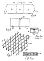
- a typical underground tank 1 for storage of petroleum products and chemicals generally.
- the tank 1 may, for example, be an underground petroleum products storage tank located at a service or filling station and comprises a main cylindrical body 20 with domed ends 21.
- the tank 1 typically has a generally centrally disposed manway 23.
- the storage tank 1 is lined in situ by accessing the tank 1 through the manway 23.
- the inner surface 7 of the tank wall is first cleaned using water jetting to remove scale, rust and surface contaminants.
- the tank internal wall is then inspected to ascertain any leak areas or perforations.
- a full inspection of the tank is carried out using an ultrasonic wall thickness gauge to establish any internal/external corrosion patterns. Any resultant defects are repaired using an epoxy filler.
- the striker plate which is a steel plate below the manway 23, is removed. Weld spatters, laminations etc may be removed by grinding.
- a keying means is then provided on the inner surface 7 of the tank 1. This is achieved by grit blasting using re-usable chilled iron grit.
- a corrosion barrier coating 16 is then applied to the keying means.
- the coating 16 is a glassflake epoxy resin which is applied to a minimum dry film thickness of 1000 microns, typically using airless spray equipment.
- the integrity of the barrier is tested to identify any pinholes on the lining substrate.
- Sheets of high density polyethylene (HDPE) interstitial grid 10 are bonded to an adhesive applied to the coating 16, forming an air gap which is typically about 5 mm.
- the grid 10 has a polyester mat 11 bonded to one side and the grid 10 is installed with the mat 11 facing into the tank.
- the grid 10 may be of any suitable mouldable/flexible material capable of substantially following the contours of the tank to be lined.
- the grid may be of a metallic mesh such as an aluminium mesh.
- the grid may also be of a suitable composite material. It may also be coated. Different grids may be applied at different locations. The construction of the grids provides an interstitial space between the inner and outer walls of the lined tank in which any vapour and/or liquid leakage is retained and detected.
- a pliable glass reinforced plastics layer preferably of GRP material is applied to the grid.
- the GRP is an ultra violet (UV) light curable material in a sheet form.
- a matrix of isophthalic resin, e-type glass reinforcement, inert fillers and a photoinitiator is sandwiched between two nylon films. The nylon films minimise emissions and facilitate handling and shaping. A further protective film to protect against daylight exposure is provided.
- the GRP material has a styrene content of approximately 6% which substantially reduces emissions of volatile organics from the product.
- One such material is available under the brand Fibertech from Pomona International Limited trading as Fibertech of Ireland.
- the GRP material is first cut to size from a roll.
- the inner protective film is removed and the GRP is applied to the prepared surface.
- the GRP material is smoothed and moulded to form an internal tank shell.
- Adjacent sheets 30, 31 of the GRP material is preferably butt jointed as illustrated in Fig. 5 and the joint 32 is covered by a tape of the same GRP material.
- the outer UV protective layer is then removed from the GRP layer which is exposed to UV rays to cure the material and to form a hardened inner liner shell for the tank.
- the GRP material is exposed to high powered UV lamps until it has fully cured resulting in a strong impermeable and hygienic shell within the tank 1.
- the curing time is generally a maximum of 60 minutes and is usually less than 30 minutes.
- an internal pressure is generally applied to the tank during curing.
- the applied pressure is typically 2 bar.
- the tank is lined in three separate stages. Referring to Fig. 4, for lining, the tank is divided into three zones 25, 26, 27, two 25, 26 at the ends 21 and one 27 between the end zones 25 and 26 and adjacent the manway 23. In the lining procedure the first zone 25 is first lined as described above. The vessel tank is evacuated through the manway 23 for curing this zone 25. This procedure is repeated for the second zone 26. The mid-zone 27 is then lined and cured. This division of the tank into zones for lining optimises the lining procedure while ensuring safety of the lining operators
- a suitable coating layer 2 may then be applied to the cured GRP layer 5.
- the barrier coating 2 is a glassflake epoxy which is applied to a minimum dry film thickness of 1000 microns using airless spray equipment.
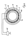
- An ultrasonic leak monitoring transducer 40 is installed in the interstitial space defined by the grid 10 at lower section of the tank.
- a vapour monitor sampling tube 41 is also installed in the interstitial space at the lower section of the tank.
- All cables and the sampling tube are fed through a predrilled aperture, adjacent to the tank manway flange, the cables and sampling tube are bedded in Epoxy and shrouded with strips of the GRP material described above.
- the transducer 40 and vapour monitor sampling tube 41 are connected to a control box 45, located in a designated safe area.
- An audible and/or visual alarm are connected to the control box 45. Should liquid or vapour be detected within the interstitial space a signal is sent to the control box 45 which will set off both audible and visual alarms. On the initiation of the alarm an auto-time counter will begin to record the detection period.
- Conditions inside the tank are artificially controlled to maintain a target temperature (minimum) 15°C throughout the application.
- a relative humidity 50%-60% average (maximum 80%) is also maintained.
- temperature will be elevated to +30°C to accelerate cure.
- the invention provides a method of tank lining which is extremely effective and efficient both in terms of material costs and installation costs.
Landscapes
- Mechanical Engineering (AREA)
- Engineering & Computer Science (AREA)
- Application Of Or Painting With Fluid Materials (AREA)
- Lining Or Joining Of Plastics Or The Like (AREA)
- Working Measures On Existing Buildindgs (AREA)
- Moulding By Coating Moulds (AREA)
- Electrical Discharge Machining, Electrochemical Machining, And Combined Machining (AREA)
- Casting Or Compression Moulding Of Plastics Or The Like (AREA)
- Supply Devices, Intensifiers, Converters, And Telemotors (AREA)
- Details Of Rigid Or Semi-Rigid Containers (AREA)
- Testing Resistance To Weather, Investigating Materials By Mechanical Methods (AREA)
- Examining Or Testing Airtightness (AREA)
- Sampling And Sample Adjustment (AREA)
Claims (33)
- Verfahren zum Auskleiden eines Lagertanks (1), das die folgenden Schritte umfasst,
Vorsehen eines Verkeilungsmittels auf der Innenfläche (7) des Tanks;
Aufbringen eines Korrosionssperrüberzugs (16) auf dem Verkeilungsmittel;
Anbringen eines Zwischengitters (10) an dem Tank;
Auflegen eines biegsamen glasverstärkten Kunststoffmaterials auf das Gitter; und
Aussetzen des glasverstärkten Kunststoffmaterials Ultraviolettstrahlen, um das Material auszuhärten und eine erhärtete innere Auskleidungsschale für den Tank zu bilden. - Verfahren nach Anspruch 1, bei dem das Zwischengitter (10) durch vorgefertigte Bahnen aus flexiblem Material vorgesehen wird.
- Verfahren nach Anspruch 1 oder 2, bei dem das Gitter (10) durch Klebstoff an den Korrosionssperrüberzug (16) gebunden wird.
- Verfahren nach einem vorhergehenden Anspruch, bei dem das Gitter (10) ein Verkleidungsmaterial umfasst, das zum Aufnehmen des glasverstärkten Kunststoffmaterials aufgebracht wird.
- Verfahren nach Anspruch 4, bei dem die Verkleidung eine Polyestermatte (11) ist, die an eine Seite des Gitters (10) gebunden wird.
- Verfahren nach einem vorhergehenden Anspruch, bei dem wenigstens ein Teil des Gitters (10) aus einem Kunststoffmaterial besteht.
- Verfahren nach einem der Ansprüche 1 bis 6, bei dem wenigstens ein Teil des Gitters (10) aus einem Verbundmaterial besteht.
- Verfahren nach einem der Ansprüche 1 bis 5, bei dem wenigstens ein Teil des Gitters (10) aus einem Siebmaterial besteht.
- Verfahren nach Anspruch 8, bei dem das Sieb ein Metallsieb ist.
- Verfahren nach Anspruch 9, bei dem das Sieb ein Aluminiumsieb ist.
- Verfahren nach Anspruch 6, bei dem das Gitter (10) aus Polyethylenmaterial hoher Dichte besteht.
- Verfahren nach einem vorhergehenden Anspruch, bei dem der Tank (1) für die Auskleidung in eine Anzahl von Zonen (25, 26, 27) unterteilt wird, die getrennt ausgekleidet werden.
- Verfahren nach Anspruch 12, bei dem die letzte auszukleidende Zone an ein Einstiegsloch (23) in den Tank angrenzt.
- Verfahren nach einem der Ansprüche 2 bis 13, bei dem die Bahnen aus biegsamem glasverstärktem Kunststoffmaterial abschnittsweise auf das Gitter aufgebracht werden, wobei die Außenkanten der Abschnitte stumpf aneinandergefügt werden.
- Verfahren nach Anspruch 14, bei dem die Verbindungsstellen zwischen benachbarten Bahnen mit einem Glasfaserkunststoffband bedeckt werden.
- Verfahren nach einem vorhergehenden Anspruch, das den Schritt umfasst:Aufbringen eines Überzugs auf die erhärtete Glasfaserkunststoffauskleidung.
- Verfahren nach einem vorhergehenden Anspruch, bei dem das Verkeilungsmittel durch Putzstrahlen der Innenfläche des Tanks vorgesehen wird.
- Verfahren nach einem vorhergehenden Anspruch, das den Schritt umfasst:Reinigen der Innenfläche (7) des Tanks (1) vor Vorsehen des Verkeilungsmittels.
- Verfahren nach Anspruch 18, bei dem die Innenfläche (7) durch Wasserstrahlreinigung gereinigt wird.
- Verfahren nach einem vorhergehenden Anspruch, bei dem die Korrosionssperre ein Glasflocken-Epoxidharz ist.
- Verfahren nach Anspruch 20, bei dem die Korrosionssperrschicht bis zu einer trockenen Filmdicke von mehr als 1000 Mikron aufgebracht wird.
- Verfahren nach einem vorhergehenden Anspruch, das vor Aufbringung einer Korrosionsschicht die folgenden Schritte umfasst:Inspizieren der Innenwand des Tanks; undReparieren jeglicher Mängel in der Tankwand.
- Verfahren nach einem vorhergehenden Anspruch, bei dem der Glasfaserkunststoff UV-Strahlung durch Richten von UV-Lampen auf die Glasfaserkunststoffschicht ausgesetzt wird.
- Verfahren nach einem vorhergehenden Anspruch, bei dem das Glasfaserkunststoffmaterial mit einem äußeren Schutzfilm bedeckt ist, der entfernt wird, um das Glasfaserkunststoffmaterial UV-Strahlung auszusetzen.
- Verfahren nach einem der Ansprüche 16 bis 24, bei dem der Glasfaserkunststoffüberzug ein Glasflocken-Epoxidharz ist.
- Verfahren nach einem vorhergehenden Anspruch, bei dem der Tank ein unterirdischer Flüssigkeitslagertank ist.
- Tank, immer wenn ein solcher durch ein Verfahren nach einem vorhergehenden Anspruch ausgekleidet ist.
- Tank nach Anspruch 27, der eine Tankwand, Verkeilungsmittel auf der Innenfläche (7) der Tankwand, einen Korrosionssperrüberzug (16) aufgebracht auf dem Verkeilungsmittel, ein Zwischengitter (10) angebracht an dem Tank, und UV-gehärtetes glasfaserverstärktes Material umfasst, das auf das Gitter gelegt wird, welches eine gehärtete innere Auskleidungsschale für den Tank bildet.
- Tank nach Anspruch 27 oder 28, der einen Leckagekontrollmesswandler (40) in dem durch das Gitter (10) begrenzten Zwischenraum umfasst.
- Tank nach einem der Ansprüche 27 bis 29, der ein Dampfkontrollmittel in dem durch das Gitter (10) begrenzten Zwischenraum umfasst.
- Tank nach Anspruch 30, bei dem das Dampfkontrollmittel ein Dampfentnahmerohr (41) umfasst.
- Tank nach einem der Ansprüche 29 bis 31, der ein Alarmnuttel verknüpft mit dem Kontrollmittel umfasst.
- Tank nach Anspruch 32, bei dem der Alarm von dem Tank (1) entfernt angebracht ist.
Applications Claiming Priority (3)
| Application Number | Priority Date | Filing Date | Title |
|---|---|---|---|
| IE980996 | 1998-12-01 | ||
| IE980996 | 1998-12-01 | ||
| PCT/IE1999/000121 WO2000032394A1 (en) | 1998-12-01 | 1999-11-30 | Tank lining |
Publications (2)
| Publication Number | Publication Date |
|---|---|
| EP1137536A1 EP1137536A1 (de) | 2001-10-04 |
| EP1137536B1 true EP1137536B1 (de) | 2003-03-19 |
Family
ID=11041944
Family Applications (1)
| Application Number | Title | Priority Date | Filing Date |
|---|---|---|---|
| EP99956295A Expired - Lifetime EP1137536B1 (de) | 1998-12-01 | 1999-11-30 | Auskleidung für tanks |
Country Status (9)
| Country | Link |
|---|---|
| US (2) | US20020020490A1 (de) |
| EP (1) | EP1137536B1 (de) |
| AT (1) | ATE234726T1 (de) |
| AU (1) | AU1292600A (de) |
| DE (1) | DE69906126T2 (de) |
| ES (1) | ES2195635T3 (de) |
| GB (1) | GB9903711D0 (de) |
| IE (2) | IE990998A1 (de) |
| WO (1) | WO2000032394A1 (de) |
Families Citing this family (17)
| Publication number | Priority date | Publication date | Assignee | Title |
|---|---|---|---|---|
| FR2824318B1 (fr) * | 2001-05-04 | 2004-07-16 | Dominique Lepvrier | Procede de realisation d'une double paroi par stratification a partir d'une paroi initiale |
| US20080148853A1 (en) * | 2003-09-22 | 2008-06-26 | Hyeung-Yun Kim | Gas tank having usage monitoring system |
| GB0619254D0 (en) | 2006-09-29 | 2006-11-08 | Haritou Christos S | Double skin tank lining with interstitial spacer |
| NL1033185C2 (nl) * | 2007-01-08 | 2008-12-02 | Vetus Den Ouden N V | Tank. |
| JP4949879B2 (ja) * | 2007-02-01 | 2012-06-13 | テクノネット株式会社 | タンクライニング施工方法、及びタンク内表面ライニング構造 |
| US9931927B2 (en) * | 2009-06-12 | 2018-04-03 | Material Engineering and Technical Support Services Corporation | Containment systems |
| CN101962109A (zh) * | 2010-09-30 | 2011-02-02 | 冀州市中意复合材料有限公司 | 一种具有双壁结构内防腐层的储油罐及其制备方法 |
| ES2430197B1 (es) * | 2012-04-16 | 2014-07-01 | Jos� Luis PE�A G�MEZ | Procedimiento para transformar un tanque existente de simple pared en otro de doble pared intrínsecamente seguro |
| CN102700858A (zh) * | 2012-06-07 | 2012-10-03 | 冀州澳科中意石油设备有限公司 | 具有防静电性能的玻璃钢储油罐体或管道 |
| CN103738611A (zh) * | 2014-01-10 | 2014-04-23 | 冀州澳科中意石油设备有限公司 | 一种柴油尾气处理液储存罐及其制备方法 |
| GB201503757D0 (en) | 2015-03-05 | 2015-04-22 | Haritou Christos S And Fada Alan | Apparatus and method for providing an interstitial space |
| FR3054532B1 (fr) * | 2016-08-01 | 2020-12-25 | Nov Tech | Cuve a double paroi et procede de fabrication de ladite cuve |
| WO2018065743A1 (en) | 2016-10-03 | 2018-04-12 | Christos Haritou | Supported wall skin with interstitial spacer |
| CN109051392B (zh) * | 2018-05-29 | 2019-07-16 | 深圳市百事达卓越科技股份有限公司 | 埋地油罐加固方法 |
| GB2587035B (en) * | 2019-09-05 | 2024-05-08 | Sotirious Haritou Christos | Wall structure monitoring System |
| GB201814458D0 (en) * | 2018-09-05 | 2018-10-17 | Haritou Christos Sotirious | Double skin structure with interstitial spacer |
| CN112606944A (zh) * | 2020-12-18 | 2021-04-06 | 武昌船舶重工集团有限公司 | 一种含环氧内衬的船用低压钢质油、水柜及其制作方法 |
Family Cites Families (14)
| Publication number | Priority date | Publication date | Assignee | Title |
|---|---|---|---|---|
| US3475260A (en) * | 1965-05-18 | 1969-10-28 | William S Stokes | Laminated joint structure defining a fluid leakage barrier |
| US3669787A (en) * | 1968-08-08 | 1972-06-13 | Minnesota Mining & Mfg | Flexible deformable self-supporting glass frit sealing tape |
| US3723234A (en) * | 1971-04-27 | 1973-03-27 | Chapman Ind Inc | Knit reinforcing fabric and resin laminate |
| CH548837A (de) * | 1972-03-15 | 1974-05-15 | Kunststoffwerk Ag | Verfahren zum auskleiden eines oelbehaelters und nach dem verfahren ausgekleideter oelbehaelter. |
| CA1052302A (en) * | 1975-05-27 | 1979-04-10 | Combustion Engineering | Composite articles |
| FR2391834A1 (fr) * | 1976-11-12 | 1978-12-22 | Massimi Pierre | Procede pour le revetement en matiere inerte de parois en acier en contact avec un fluide |
| DE2904578A1 (de) * | 1979-01-19 | 1980-07-31 | Borsari & Co | Doppelwandiger behaelter und verfahren zu dessen herstellung |
| JPS6044144B2 (ja) * | 1981-06-09 | 1985-10-02 | 株式会社クボタ | 耐久性にすぐれた鋳鋼製荷油管 |
| US5675941A (en) * | 1983-12-09 | 1997-10-14 | Dykmans; Maximiliaan J. | Method and apparatus for constructing prestressed structures utilizing a membrane and floating dome assembly |
| GB2164293A (en) * | 1984-08-31 | 1986-03-19 | Motoplat | Import resistant fuel tanks |
| US4662959A (en) * | 1984-10-31 | 1987-05-05 | Morgan Howard F | Fiberglass gasoline tank repair process |
| JPH05261858A (ja) * | 1992-03-23 | 1993-10-12 | Nippon Steel Corp | ポリオレフィン被覆鋼材 |
| CH686722A5 (de) * | 1993-09-09 | 1996-06-14 | Sika Ag | Verfahren zum Abdichten und Schuetzen von Auffangwannen und Behaeltern. |
| FR2733489B1 (fr) * | 1995-04-25 | 2000-05-19 | Galan Inchaurbe Jose Ma Javier | Reservoir/citerne perfectionne |
-
1999
- 1999-02-19 GB GBGB9903711.1A patent/GB9903711D0/en not_active Ceased
- 1999-11-30 AU AU12926/00A patent/AU1292600A/en not_active Abandoned
- 1999-11-30 WO PCT/IE1999/000121 patent/WO2000032394A1/en active IP Right Grant
- 1999-11-30 IE IE19990998A patent/IE990998A1/en not_active IP Right Cessation
- 1999-11-30 ES ES99956295T patent/ES2195635T3/es not_active Expired - Lifetime
- 1999-11-30 DE DE69906126T patent/DE69906126T2/de not_active Expired - Fee Related
- 1999-11-30 AT AT99956295T patent/ATE234726T1/de not_active IP Right Cessation
- 1999-11-30 EP EP99956295A patent/EP1137536B1/de not_active Expired - Lifetime
- 1999-11-30 IE IE20000541A patent/IES20000541A2/en not_active IP Right Cessation
-
2001
- 2001-06-01 US US09/872,906 patent/US20020020490A1/en not_active Abandoned
-
2004
- 2004-03-15 US US10/800,009 patent/US20050077293A1/en not_active Abandoned
Also Published As
| Publication number | Publication date |
|---|---|
| GB9903711D0 (en) | 1999-04-14 |
| WO2000032394A1 (en) | 2000-06-08 |
| ATE234726T1 (de) | 2003-04-15 |
| IES20000541A2 (en) | 2001-06-13 |
| IE990998A1 (en) | 2000-07-12 |
| AU1292600A (en) | 2000-06-19 |
| DE69906126T2 (de) | 2004-01-29 |
| ES2195635T3 (es) | 2003-12-01 |
| DE69906126D1 (de) | 2003-04-24 |
| US20020020490A1 (en) | 2002-02-21 |
| EP1137536A1 (de) | 2001-10-04 |
| US20050077293A1 (en) | 2005-04-14 |
Similar Documents
| Publication | Publication Date | Title |
|---|---|---|
| EP1137536B1 (de) | Auskleidung für tanks | |
| US6276401B1 (en) | High temperature composite pipe wrapping system | |
| US6688338B2 (en) | Secondary containment system for pipelines | |
| CA2142816C (en) | Methods for repairing pipe | |
| CA2685709C (en) | Double skin tank lining with interstitial spacer | |
| US8881925B1 (en) | Protective steel membrane system and method of erection for secondary containment for an above ground storage tank | |
| CZ20003893A3 (cs) | Nádrľ s plochým dnem s protiúnikovou výstelkou a způsob vybavování této nádrľe protiúnikovou výstelkou | |
| JPH0649419A (ja) | 耐圧中空ボデーを補強する多層テープ及びその製法 | |
| EP3847012B1 (de) | Doppelhautstruktur mit interstitiellem abstandshalter | |
| EP2706021B1 (de) | Verfahren zur Herstellung einer inneren Metallwand in einem Tank und Tank mit einer doppelten Wand | |
| IE980995A1 (en) | Tank lining | |
| US5152859A (en) | Method of making a double walled cylindrical-shaped storage tank with independent monitoring of tank areas | |
| IES20000542A2 (en) | Tank lining | |
| GB2413587A (en) | Plastics lining for a tank or pipe providing a space between the lining and the wall to be lined | |
| JP2020037741A (ja) | 屋外石油タンクの開放検査時におけるコーティング剥離部の防錆方法 | |
| JPH01210688A (ja) | 配管欠陥部の補修・補強方法 | |
| LINING | WASTEWATER DEPARTMENT STANDARD SPECIFICATIONS SECTION 404 CURED IN PLACE LINING OF SANITARY SEWERS | |
| Bigante et al. | Comparison of Material Costs Between Dual Laminate Fiberglass Reinforced Plastic vs. Acid Resistant Brick Lined Steel | |
| Peloquin | Service Life Extension Option for Large-Diameter Potable-Water Transmission Pipelines | |
| Miller | Evaluation and Repair of Epoxy Fiberglass Reinforced Lining Systems | |
| MAINS | STANDARD SPECIFICATIONS FOR CONSTRUCTING SANITARY SEWER FACILITIES DIVISION III-CONSTRUCTION SPECIFICATIONS SECTION 5 REHABILITATION OF SANITARY SEWER MAINS |
Legal Events
| Date | Code | Title | Description |
|---|---|---|---|
| PUAI | Public reference made under article 153(3) epc to a published international application that has entered the european phase |
Free format text: ORIGINAL CODE: 0009012 |
|
| 17P | Request for examination filed |
Effective date: 20010727 |
|
| AK | Designated contracting states |
Kind code of ref document: A1 Designated state(s): AT BE CH CY DE DK ES FI FR GB GR IE IT LI LU MC NL PT SE |
|
| AX | Request for extension of the european patent |
Free format text: AL;LT;LV;MK;RO;SI |
|
| GRAG | Despatch of communication of intention to grant |
Free format text: ORIGINAL CODE: EPIDOS AGRA |
|
| 17Q | First examination report despatched |
Effective date: 20011217 |
|
| GRAG | Despatch of communication of intention to grant |
Free format text: ORIGINAL CODE: EPIDOS AGRA |
|
| GRAH | Despatch of communication of intention to grant a patent |
Free format text: ORIGINAL CODE: EPIDOS IGRA |
|
| GRAH | Despatch of communication of intention to grant a patent |
Free format text: ORIGINAL CODE: EPIDOS IGRA |
|
| GRAA | (expected) grant |
Free format text: ORIGINAL CODE: 0009210 |
|
| AK | Designated contracting states |
Designated state(s): AT BE CH CY DE DK ES FI FR GB GR IT LI LU MC NL PT SE |
|
| PG25 | Lapsed in a contracting state [announced via postgrant information from national office to epo] |
Ref country code: LI Free format text: LAPSE BECAUSE OF FAILURE TO SUBMIT A TRANSLATION OF THE DESCRIPTION OR TO PAY THE FEE WITHIN THE PRESCRIBED TIME-LIMIT Effective date: 20030319 Ref country code: GR Free format text: LAPSE BECAUSE OF FAILURE TO SUBMIT A TRANSLATION OF THE DESCRIPTION OR TO PAY THE FEE WITHIN THE PRESCRIBED TIME-LIMIT Effective date: 20030319 Ref country code: FI Free format text: LAPSE BECAUSE OF FAILURE TO SUBMIT A TRANSLATION OF THE DESCRIPTION OR TO PAY THE FEE WITHIN THE PRESCRIBED TIME-LIMIT Effective date: 20030319 Ref country code: CH Free format text: LAPSE BECAUSE OF FAILURE TO SUBMIT A TRANSLATION OF THE DESCRIPTION OR TO PAY THE FEE WITHIN THE PRESCRIBED TIME-LIMIT Effective date: 20030319 Ref country code: AT Free format text: LAPSE BECAUSE OF FAILURE TO SUBMIT A TRANSLATION OF THE DESCRIPTION OR TO PAY THE FEE WITHIN THE PRESCRIBED TIME-LIMIT Effective date: 20030319 |
|
| REG | Reference to a national code |
Ref country code: GB Ref legal event code: FG4D |
|
| REG | Reference to a national code |
Ref country code: CH Ref legal event code: EP |
|
| REG | Reference to a national code |
Ref country code: IE Ref legal event code: FG4D |
|
| REF | Corresponds to: |
Ref document number: 69906126 Country of ref document: DE Date of ref document: 20030424 Kind code of ref document: P |
|
| PG25 | Lapsed in a contracting state [announced via postgrant information from national office to epo] |
Ref country code: SE Free format text: LAPSE BECAUSE OF FAILURE TO SUBMIT A TRANSLATION OF THE DESCRIPTION OR TO PAY THE FEE WITHIN THE PRESCRIBED TIME-LIMIT Effective date: 20030619 Ref country code: DK Free format text: LAPSE BECAUSE OF FAILURE TO SUBMIT A TRANSLATION OF THE DESCRIPTION OR TO PAY THE FEE WITHIN THE PRESCRIBED TIME-LIMIT Effective date: 20030619 |
|
| PG25 | Lapsed in a contracting state [announced via postgrant information from national office to epo] |
Ref country code: PT Free format text: LAPSE BECAUSE OF FAILURE TO SUBMIT A TRANSLATION OF THE DESCRIPTION OR TO PAY THE FEE WITHIN THE PRESCRIBED TIME-LIMIT Effective date: 20030620 |
|
| LTIE | Lt: invalidation of european patent or patent extension |
Effective date: 20030319 |
|
| REG | Reference to a national code |
Ref country code: CH Ref legal event code: PL |
|
| PG25 | Lapsed in a contracting state [announced via postgrant information from national office to epo] |
Ref country code: MC Free format text: LAPSE BECAUSE OF NON-PAYMENT OF DUE FEES Effective date: 20031130 Ref country code: LU Free format text: LAPSE BECAUSE OF NON-PAYMENT OF DUE FEES Effective date: 20031130 Ref country code: CY Free format text: LAPSE BECAUSE OF FAILURE TO SUBMIT A TRANSLATION OF THE DESCRIPTION OR TO PAY THE FEE WITHIN THE PRESCRIBED TIME-LIMIT Effective date: 20031130 |
|
| ET | Fr: translation filed | ||
| PLBE | No opposition filed within time limit |
Free format text: ORIGINAL CODE: 0009261 |
|
| STAA | Information on the status of an ep patent application or granted ep patent |
Free format text: STATUS: NO OPPOSITION FILED WITHIN TIME LIMIT |
|
| 26N | No opposition filed |
Effective date: 20031222 |
|
| REG | Reference to a national code |
Ref country code: IE Ref legal event code: MM4A |
|
| PGFP | Annual fee paid to national office [announced via postgrant information from national office to epo] |
Ref country code: GB Payment date: 20080923 Year of fee payment: 10 |
|
| PGFP | Annual fee paid to national office [announced via postgrant information from national office to epo] |
Ref country code: NL Payment date: 20081128 Year of fee payment: 10 |
|
| PGFP | Annual fee paid to national office [announced via postgrant information from national office to epo] |
Ref country code: ES Payment date: 20081128 Year of fee payment: 10 |
|
| PGFP | Annual fee paid to national office [announced via postgrant information from national office to epo] |
Ref country code: BE Payment date: 20081002 Year of fee payment: 10 Ref country code: IT Payment date: 20081112 Year of fee payment: 10 |
|
| PGFP | Annual fee paid to national office [announced via postgrant information from national office to epo] |
Ref country code: FR Payment date: 20080926 Year of fee payment: 10 |
|
| PGFP | Annual fee paid to national office [announced via postgrant information from national office to epo] |
Ref country code: DE Payment date: 20090130 Year of fee payment: 10 |
|
| BERE | Be: lapsed |
Owner name: *NEW LAKE INTERNATIONAL LTD Effective date: 20091130 |
|
| REG | Reference to a national code |
Ref country code: NL Ref legal event code: V1 Effective date: 20100601 |
|
| GBPC | Gb: european patent ceased through non-payment of renewal fee |
Effective date: 20091130 |
|
| REG | Reference to a national code |
Ref country code: FR Ref legal event code: ST Effective date: 20100730 |
|
| PG25 | Lapsed in a contracting state [announced via postgrant information from national office to epo] |
Ref country code: NL Free format text: LAPSE BECAUSE OF NON-PAYMENT OF DUE FEES Effective date: 20100601 Ref country code: FR Free format text: LAPSE BECAUSE OF NON-PAYMENT OF DUE FEES Effective date: 20091130 Ref country code: BE Free format text: LAPSE BECAUSE OF NON-PAYMENT OF DUE FEES Effective date: 20091130 |
|
| PG25 | Lapsed in a contracting state [announced via postgrant information from national office to epo] |
Ref country code: DE Free format text: LAPSE BECAUSE OF NON-PAYMENT OF DUE FEES Effective date: 20100601 |
|
| PG25 | Lapsed in a contracting state [announced via postgrant information from national office to epo] |
Ref country code: GB Free format text: LAPSE BECAUSE OF NON-PAYMENT OF DUE FEES Effective date: 20091130 |
|
| PG25 | Lapsed in a contracting state [announced via postgrant information from national office to epo] |
Ref country code: IT Free format text: LAPSE BECAUSE OF NON-PAYMENT OF DUE FEES Effective date: 20091130 |
|
| REG | Reference to a national code |
Ref country code: ES Ref legal event code: FD2A Effective date: 20110411 |
|
| PG25 | Lapsed in a contracting state [announced via postgrant information from national office to epo] |
Ref country code: ES Free format text: LAPSE BECAUSE OF NON-PAYMENT OF DUE FEES Effective date: 20110329 |
|
| PG25 | Lapsed in a contracting state [announced via postgrant information from national office to epo] |
Ref country code: ES Free format text: LAPSE BECAUSE OF NON-PAYMENT OF DUE FEES Effective date: 20091201 |