EP3347640B1 - Coating/membrane repair kit - Google Patents
Coating/membrane repair kit Download PDFInfo
- Publication number
- EP3347640B1 EP3347640B1 EP16816884.7A EP16816884A EP3347640B1 EP 3347640 B1 EP3347640 B1 EP 3347640B1 EP 16816884 A EP16816884 A EP 16816884A EP 3347640 B1 EP3347640 B1 EP 3347640B1
- Authority
- EP
- European Patent Office
- Prior art keywords
- membrane
- patch
- defect
- patch member
- support member
- Prior art date
- Legal status (The legal status is an assumption and is not a legal conclusion. Google has not performed a legal analysis and makes no representation as to the accuracy of the status listed.)
- Active
Links
- 239000012528 membrane Substances 0.000 title claims description 89
- 230000008439 repair process Effects 0.000 title claims description 33
- 238000000576 coating method Methods 0.000 title claims description 16
- 239000011248 coating agent Substances 0.000 title claims description 12
- 230000007547 defect Effects 0.000 claims description 52
- 230000001681 protective effect Effects 0.000 claims description 39
- 239000002184 metal Substances 0.000 claims description 21
- 239000000853 adhesive Substances 0.000 claims description 18
- 230000001070 adhesive effect Effects 0.000 claims description 18
- 230000002093 peripheral effect Effects 0.000 claims description 18
- 239000000463 material Substances 0.000 claims description 17
- 239000012790 adhesive layer Substances 0.000 claims description 14
- 239000012705 liquid precursor Substances 0.000 claims description 13
- 239000004593 Epoxy Substances 0.000 claims description 10
- -1 preferably Substances 0.000 claims description 10
- 230000007704 transition Effects 0.000 claims description 8
- 239000012812 sealant material Substances 0.000 claims description 7
- 239000004698 Polyethylene Substances 0.000 claims description 5
- 239000007788 liquid Substances 0.000 claims description 5
- 229920000573 polyethylene Polymers 0.000 claims description 5
- 150000003673 urethanes Chemical class 0.000 claims description 5
- 239000011800 void material Substances 0.000 claims description 4
- 239000004743 Polypropylene Substances 0.000 claims description 3
- 150000001875 compounds Chemical class 0.000 claims description 3
- 229920001971 elastomer Polymers 0.000 claims description 3
- 125000003700 epoxy group Chemical group 0.000 claims description 3
- 239000004033 plastic Substances 0.000 claims description 3
- 229920003023 plastic Polymers 0.000 claims description 3
- 239000004417 polycarbonate Substances 0.000 claims description 3
- 229920000515 polycarbonate Polymers 0.000 claims description 3
- 229920000647 polyepoxide Polymers 0.000 claims description 3
- 229920000642 polymer Polymers 0.000 claims description 3
- 229920001155 polypropylene Polymers 0.000 claims description 3
- 239000004800 polyvinyl chloride Substances 0.000 claims description 3
- 239000012260 resinous material Substances 0.000 claims description 3
- 239000005060 rubber Substances 0.000 claims description 3
- 238000002347 injection Methods 0.000 claims description 2
- 239000007924 injection Substances 0.000 claims description 2
- 229920001084 poly(chloroprene) Polymers 0.000 claims description 2
- 229920005989 resin Polymers 0.000 claims description 2
- 239000011347 resin Substances 0.000 claims description 2
- 239000010703 silicon Substances 0.000 claims description 2
- 229910052710 silicon Inorganic materials 0.000 claims description 2
- 239000007787 solid Substances 0.000 claims description 2
- 230000000007 visual effect Effects 0.000 description 6
- 239000006260 foam Substances 0.000 description 5
- 229910000746 Structural steel Inorganic materials 0.000 description 3
- 238000001514 detection method Methods 0.000 description 3
- 239000003550 marker Substances 0.000 description 3
- 238000000034 method Methods 0.000 description 3
- 230000002950 deficient Effects 0.000 description 2
- 239000000203 mixture Substances 0.000 description 2
- 239000002861 polymer material Substances 0.000 description 2
- 230000007797 corrosion Effects 0.000 description 1
- 238000005260 corrosion Methods 0.000 description 1
- 230000001419 dependent effect Effects 0.000 description 1
- 238000011161 development Methods 0.000 description 1
- 230000018109 developmental process Effects 0.000 description 1
- 229920005570 flexible polymer Polymers 0.000 description 1
- 229930195733 hydrocarbon Natural products 0.000 description 1
- 150000002430 hydrocarbons Chemical class 0.000 description 1
- 238000012423 maintenance Methods 0.000 description 1
- 239000003921 oil Substances 0.000 description 1
- 239000002245 particle Substances 0.000 description 1
- 230000000704 physical effect Effects 0.000 description 1
- 238000007789 sealing Methods 0.000 description 1
- 239000000243 solution Substances 0.000 description 1
Images


Classifications
-
- F—MECHANICAL ENGINEERING; LIGHTING; HEATING; WEAPONS; BLASTING
- F16—ENGINEERING ELEMENTS AND UNITS; GENERAL MEASURES FOR PRODUCING AND MAINTAINING EFFECTIVE FUNCTIONING OF MACHINES OR INSTALLATIONS; THERMAL INSULATION IN GENERAL
- F16L—PIPES; JOINTS OR FITTINGS FOR PIPES; SUPPORTS FOR PIPES, CABLES OR PROTECTIVE TUBING; MEANS FOR THERMAL INSULATION IN GENERAL
- F16L55/00—Devices or appurtenances for use in, or in connection with, pipes or pipe systems
- F16L55/16—Devices for covering leaks in pipes or hoses, e.g. hose-menders
- F16L55/168—Devices for covering leaks in pipes or hoses, e.g. hose-menders from outside the pipe
- F16L55/1683—Devices for covering leaks in pipes or hoses, e.g. hose-menders from outside the pipe by means of a patch which is fixed on the wall of the pipe by means of an adhesive, a weld or the like
-
- F—MECHANICAL ENGINEERING; LIGHTING; HEATING; WEAPONS; BLASTING
- F16—ENGINEERING ELEMENTS AND UNITS; GENERAL MEASURES FOR PRODUCING AND MAINTAINING EFFECTIVE FUNCTIONING OF MACHINES OR INSTALLATIONS; THERMAL INSULATION IN GENERAL
- F16L—PIPES; JOINTS OR FITTINGS FOR PIPES; SUPPORTS FOR PIPES, CABLES OR PROTECTIVE TUBING; MEANS FOR THERMAL INSULATION IN GENERAL
- F16L55/00—Devices or appurtenances for use in, or in connection with, pipes or pipe systems
- F16L55/18—Appliances for use in repairing pipes
-
- F—MECHANICAL ENGINEERING; LIGHTING; HEATING; WEAPONS; BLASTING
- F17—STORING OR DISTRIBUTING GASES OR LIQUIDS
- F17C—VESSELS FOR CONTAINING OR STORING COMPRESSED, LIQUEFIED OR SOLIDIFIED GASES; FIXED-CAPACITY GAS-HOLDERS; FILLING VESSELS WITH, OR DISCHARGING FROM VESSELS, COMPRESSED, LIQUEFIED, OR SOLIDIFIED GASES
- F17C1/00—Pressure vessels, e.g. gas cylinder, gas tank, replaceable cartridge
-
- F—MECHANICAL ENGINEERING; LIGHTING; HEATING; WEAPONS; BLASTING
- F17—STORING OR DISTRIBUTING GASES OR LIQUIDS
- F17D—PIPE-LINE SYSTEMS; PIPE-LINES
- F17D5/00—Protection or supervision of installations
- F17D5/02—Preventing, monitoring, or locating loss
Definitions
- the present disclosure relates to a repair kit for repairing damaged or defective coatings or membranes covering metal pipes, tank linings or structural steel.
- the present disclosure provides a repair kit for repairing damaged or defective coatings or membranes covering metal pipes, tank linings or structural steel.
- EP0787938 discloses a device suitable for repairing membranes or coating covering metal pipes comprising a patch applicator.
- EP0341437 discloses a device suitable for repairing membranes or coating covering metal pipes comprising a syringe for holding a liquid precursor of a sealant material, and an applicator.
- Two objects of the invention are a device for repairing membranes coating metal pipes and metal storage tank in accordance with independent claims 1 and 9. Further developments of the inventions are respectively in accordance with dependent claims 2 to 8 and 10 to 15.
- a device for repairing membranes coating metal pipes and metal storage tanks which comprises a patch member having top and bottom surfaces, and a protective outer wrap having an inner bottom surface and an outer bottom surface.
- the protective outer wrap includes a recessed portion having a size and shape to receive therein the patch member such that the top surface of the patch member is in physical contact with the inner bottom surface of the recessed portion.
- a removable protective film is applied to the bottom surface of the patch member.
- the device includes a patch applicator which includes a support member having a top surface, a bottom surface, an aperture extending therethrough and an adhesive layer coated on the bottom surface. A removable protective film is applied over the adhesive for protection of the adhesive layer until the device is employed.
- the kit includes an arm having first and second end portions with the first end portion hingedly or pivotally attached to the top surface of the support member and is pivotally movable between a closed position and an open position.
- the outer bottom surface of the protective outer wrap member is detachably attached to a bottom surface of the second end portion of the arm.
- the arm has a length selected such that when in the closed position the patch member is generally centrally located in the aperture.
- the protective film located on the adhesive covering the bottom surface of the support member is peeled off and the support member is temporarily bonded on top of the membrane covering the metal with the defect centrally disposed in the aperture defined by the support member.
- the removable protective film applied to the bottom surface of the patch member is removed when the arm is in the open position thereby exposing the bottom surface of the patch member.
- the arm is then pivoted to the closed position such that the bottom surface of the patch member covers the defect, and the protective outer wrap is detached from the bottom surface of the arm and the patch applicator is detached from the membrane to leave behind the patch member on the membrane which is covered by the protective outer wrap.
- the device may include the protective outer wrap being rigid, made of a plastic, polymer material and the recessed portion defines an circumferentially disposed side wall extending outwardly away from the inner bottom surface to provide a chamfered side wall transition between said inner bottom surface and an outer peripheral circumferentially disposed side wall section that is substantially parallel to the inner bottom surface.
- the outer peripheral circumferentially disposed side wall section is coplanar with the bottom surface of the patch member and has an adhesive located thereon for bonding to the membrane.
- the patch member may have a complimentary shape matched to the recessed portion with the chamfered transition of side wall such that recessed portion is completely filled by the patch member.
- The may include a temporary removable clearly visible indicator patch for application to a defect site on the membrane for visually marking the defect site after detection of the defect and prior to temporarily bonding patch applicator to the membrane.
- the kit may include a unique identifier permanently affixed to the protective outer wrap which can be accessed at a later date and information downloaded from the identifier.
- the unique identifier may be a barcode, or it may be a radio frequency identification device (rfid).
- the patch member may be made of a conforming material such that upon application of the patch member by the patch applicator to the defect in the membrane, the conforming material fills, seals or covers a void produced by the defect.
- the patch member may be made of a polymeric material, including but not limited to polyethylene, polypropylene, polyvinylchloride (PVC) or polycarbonate as well as various other flexible polymers.
- a polymeric material including but not limited to polyethylene, polypropylene, polyvinylchloride (PVC) or polycarbonate as well as various other flexible polymers.
- a device for repairing membranes coating metal pipes and metal storage tanks comprising:
- the mould portion and the support member may be made of a polymer or plastic material, and the mould portion may be hingedly attached to the support member via a living hinge.
- the sealant material may be any one or combination of epoxies, urethanes, ultra-violet curing compounds or other resinous materials.
- the terms, “comprises” and “comprising” are to be construed as being inclusive and open ended, and not exclusive. Specifically, when used in the specification and claims, the terms, “comprises” and “comprising” and variations thereof mean the specified features, steps or components are included. These terms are not to be interpreted to exclude the presence of other features, steps or components.
- exemplary means “serving as an example, instance, or illustration,” and should not be construed as preferred or advantageous over other configurations disclosed herein.
- membrane refers to coatings and linings typically used for coating metal structures such as but not limited to pipes used in pipelines, storage tanks and the like to give a few non-limiting examples.
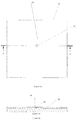
- Figures 1a is a top view of a section of a pipe 10 covered with a membrane 12 and a defect 14 shown in the membrane 12.
- Figure 1b is a sectional side view of the membrane coated pipe 10 of Figure 1a showing the defect 14.
- Figure 2 is a top view of a section of pipe 10 covered with the membrane 12 and a defect 14 shown in the membrane 12 covered by a temporary visual marker 16.
- the temporary visual markers may be brightly colored to be easily seen.
- the markers 16 may be applied as each defect 14 is identified along a section of pipe, and after the detection process is completed the workers may return to each site containing a marker 16 which is then removed and the repair device is applied as will be discussed below.
- a repair device for membranes coating metal pipes and metal storage tanks is shown mounted on a membrane 12 in the open position and partially disassembled.
- the repair device includes a patch member 30 having top and bottom surfaces, a protective outer wrap 32 having an inner bottom surface and an outer bottom surface.
- the protective outer wrap 32 includes a recessed portion having a size and shape to receive therein the patch member 30 such that the top surface of the patch member 30 is in physical contact with the inner bottom surface of the recessed portion.
- the device includes a removable protective film 28 applied to the bottom surface of the patch member 30.
- the device further includes a patch applicator 20 which in turn includes a support member or open frame 22 having a top surface, bottom surface with the support member defining an aperture 40 extending therethrough and an adhesive layer coated on said bottom surface and a removable protective film 38 applied over the adhesive layer.
- aperture 40 is shown as being a circular aperture as formed by support member 22 but it will be appreciated that support member 22 need not be circular, it could be partially circular or it could be any other shape, as long as the aperture is large enough so that the patch 30 can be pressed down onto the membrane within the open frame defined by frame 22.
- the device includes an arm 24 having first and second end portions, the first end portion is hingedly or pivotally attached to the top surface of the support member 22 and pivotally movable between a closed position ( Figure 4a ) and an open position ( Figure 5 ).
- the outer bottom surface of the protective outer wrap member 32 is detachably attached to a bottom surface of the second end portion of the arm 24.
- the arm 24 has a length selected such that when in the closed position the patch member 30 is generally centrally located in the aperture 40. It will be appreciated that while in the Figures the end portion of arm 24 to which patch 30 is releasibly attached is not exactly the same size as patch 30, it may be constructed to be the same size, or it may be different.
- the size and shape of the patch member 30 is not restricted to being disc shaped, they may be square, rectangular depending on the circumstances.
- the patch kit may be produced to applying elongate rectangular patches to membranes such as in cases where a membrane has a split or elongate crack.
- the applicator may be configured and shaped to be longer than its width.
- the protective outer wrap 32 is rigid or a flexible tape and the recessed portion defines a circumferentially disposed side wall 42 extending outwardly away from the inner bottom surface 44 to provide a side wall chamfered transition between the inner bottom surface 44 and an outer peripheral circumferentially disposed side wall section 46 that is substantially parallel to the inner bottom surface 44.
- the outer peripheral circumferentially disposed side wall section being coplanar with the bottom surface of the patch member 30 which is contact with the top of membrane 12, and has an adhesive located thereon for bonding the side wall section 46 to said membrane 12.
- the chamfered transition of the side wall 42 may have an angle of about 45° with respect to the inner bottom surface 44 of the protective outer wrap 32. This angled or chamfered outer wrap helps to protect patch 30 once the pipe has been buried in the event earth moves over the patch 30 and protective outer wrap 32 as the angle will help deflect the earth passing over it much better than a wrap not having a chamfered transition.
- the patch member 30 may have a complimentary shape matched to the recessed portion with of protective outer wrap 32 so that the chamfered transition of side wall 42 is completely filled by the patch member 30.
- the kit may include unique identifier permanently 26 affixed to either the top of the protective outer wrap 32 or it may be sandwiched between the inner bottom surface 44 of wrap 32 and the top surface of patch member 30, see Figure 4c .
- the unique identifier 26 may be a barcode, or it may be a radio frequency identification device (RFID).
- the patch member may be made of a conforming material such that upon application of the patch member 30 by the patch applicator 20 to the defect 14 in the membrane 12, the conforming material fills a void produced by the defect 14.
- the patch member 30 may be made of a polymeric material, such as, but not limited to, polyethylene, polypropylene, polyvinylchloride (PVC) and polycarbonate.
- the patch member 30 may be made from flexible non-curing materials, multi component resins (curing or non-curing) urethanes, polymers or other materials to mention a few non-limiting examples.
- the user then applies the patch applicator 20 to the defect by removing protective film 38 is removed from the bottom surface of the support member 22 thus exposing the adhesive layer on the bottom of support member 22 and the latter is temporarily bonded on the membrane 12 of the pipe 10 such that defect 14 in the membrane 12 is generally centrally located within the aperture 40 defined by support member 22.
- the arm 24 is pivoted to the open position and the removable protective film 28 applied to the bottom surface of the patch member 30 is removed when the arm 24 to expose the bottom surface of the patch member 30.
- Arm 24 is then pivoted to the closed position such that the bottom surface of the patch member 30 covers the defect 14 and the person applying the patch ensures the patch member 30 is pressed into the defect.
- the patch member 30, when made of a conforming adhesive material will partially or totally fill the void defined by the defect 14 and bond to membrane 12.
- the person applying the patch then detaches the protective outer wrap 32 from the bottom surface of the arm 24 and the patch applicator 20 is detached from the membrane 12 to leave behind patch member 30 on the membrane 12 which in turn is covered by the protective outer wrap 32.
- the process is repeated with all defect sites until the given section of pipe has been treated.
- the device disclosed in Figures 1 to 6b may be provided in the form of a kit including the patch member and the applicator provided as separate components forming the kit.
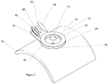
- Figure 7 shows a perspective view of another embodiment of a repair device for repairing a membrane defect shown generally at 50 with the device shown on a membrane coat 60 on a pipe 61 during the operation of repairing the membrane 60.
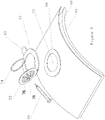
- Figure 8 shows a perspective view of the repair device 50 with the device shown in the open position while coupled to the top surface of the membrane 60.
- Repair device 50 includes ring 62 that may be made of a rigid polymer material. Ring 62 is preferably produced having a curvature of similar radius matching that of the pipe 61.
- a repair kit may be produced for repairing different diameter pipes. Typical standard pipes include 10", 16", 24" etc. diameter pipes so that a repair kit could include multiple repair devices with a set number included for a given diameter of pipe.
- Curved annular ring 62 includes a tab 63 integrally formed therewith which is useful for a user to remove device 50 from the membrane once the patch operation has been completed.
- a mould portion (also referred to as a lid) 64 of device 50 is connected to ring 62 by way of a living hinge 70 or other hinge design so that lid portion 64 can be moved from a closed position, see Figure 7 , to an open position, see Figure 8 .
- mould portion 64 has a centrally disposed hole 76 extending through it which has a diameter sufficient to receive the leading end of a syringe tube 66, Shown in Figures 7 , 9 , 10a and 10b .
- Lid portion 64 also includes several vent and witness holes 78 disposed around the circular periphery of the mould section 64.
- the repair device 50 is placed on the membrane 60 with annular ring 62 positioned around the temporary visual indicators 16 covering defect 72 with the defect located approximately in the center of the ring 62.
- Defects 72 may be a hole, a partial tear etc., in the membrane, with such defects typically being referred to as a "holiday".
- repair device 50 includes a ring 62 adhesive connector foam 68 which is an annular ring of the same diameter as ring 62 which has adhesive on both sides so that the ring 62 can be temporarily bonded to the top surface of membrane 60.
- the inner surface of mould section 64 has a peripheral raised shoulder such that when section 64 is moved to the closed position, a chamber is produced between the top of the membrane 60 and mould section 64 which will be filled with the sealing epoxy.
- repair device 50 includes a mould adhesive connector foam 74 located on the raised peripheral shoulder and which has adhesive on both sides so that the mould portion 64 can be temporarily bonded to the top surface of membrane 60 located on pipe 61 when in the closed position.
- Figure 10b shows a cross sectional view taken along the line A-A of Figure 10a as can be seen when repair device 50 is mounted on membrane 60 the radius of curvature of ring 62 exactly matches the curvature of the pipe 61 so there are no gaps between ring 62 and membrane 60.
- the holiday defects in a given length of pipe are first detected, and a temporary identification patch with a light adhesive is placed over the defect, the patch being brightly colored in one example for easy visual detection.
- the user removes the protective sheet on the bottom of ring 62 adhesive connector foam 68, centers device 50 over the defect 72 (after the temporary identification patch has been removed) with the defect in the center of ring 62 and presses down to temporarily bond ring 62 to the top of the membrane surface 60.
- mould portion 64 is pivoted from the open position ( Figure 10b ) to the closed position ( Figure 7 ) whereby the bottom surface of adhesive connector foam 74 bonds mould portion 64 to the top surface of membrane 60, thereby forming a seal.
- the syringe 66 filled with epoxy, is inserted with its leading tip into hole 76 in mould portion 64.
- the user then activates the plunger in syringe 66 to inject the epoxy into the chamber defined between the closed mould section 64 and the top surface of membrane 60 encircled by ring 62 at the center of which is defect 72.
- any excess epoxy will flow out through the holes 78 which will inform the user that the chamber is filled with epoxy and no more is needed. It is noted that when injecting the liquid into the chamber air will be expelled through holes 78 as it is being filled with the liquid to prevent air bubbles being formed in the patch.
- the epoxy is allowed to set for a few minutes and once it is set the user can remove the entire repair device 50 from the top surface of membrane 60 by prying up on tab 63 thereby releasing adhesive rings 68 and 74 from membrane 60.
- Figures 10c and 10d show a particular embodiment of the repair device 50 wherein the patch member includes a rubber O-ring 84 affixed to the peripheral edge of lid 64 which replaces ring 74 in Figure 10b and may be made from a variation of materials including but not limited to rubber, silicon, polyethylene and neoprene.
- the lid 64 bonds to adhesive ring 82 and the O-ring forms a seal that will prevent any liquid from flowing out of the enclosed chamber.
- the adhesive ring 82 could be either where it is shown in Figure 10C on the outer ring 62, or on the lid 64 on the outside of the peripheral edge, or the recessed edge.
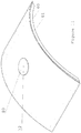
- Figure 11 shows the patched membrane 60 after remove of the repair device 50 leaving behind the patch 80 covering the defect 72.
- the material from which patch 80 is made may be made of any one or combination of epoxies, urethanes, ultra-violet curing compounds or other resinous materials.
- the device disclosed and illustrated in Figures 7 to 11 may be provided in the form of a kit including the syringe holding the liquid precursor of the sealant material and the applicator being provided as separate components forming the kit.
Landscapes
- Engineering & Computer Science (AREA)
- General Engineering & Computer Science (AREA)
- Mechanical Engineering (AREA)
- Pipe Accessories (AREA)
Description
- The present disclosure relates to a repair kit for repairing damaged or defective coatings or membranes covering metal pipes, tank linings or structural steel.
- Currently there is no standardized repair solution for addressing the repair of small area, defects or holidays on pipeline coatings, tank linings or structural steel members. Each contractor contracted to conduct repairs does these repairs a bit differently from each other. Generally the process of repair is time consuming and labour intense. Since the repairs are carried out in different ways with different personnel, there is potential for failure of these repaired sections.
- The present disclosure provides a repair kit for repairing damaged or defective coatings or membranes covering metal pipes, tank linings or structural steel.
EP0787938 discloses a device suitable for repairing membranes or coating covering metal pipes comprising a patch applicator.EP0341437 discloses a device suitable for repairing membranes or coating covering metal pipes comprising a syringe for holding a liquid precursor of a sealant material, and an applicator. - Two objects of the invention are a device for repairing membranes coating metal pipes and metal storage tank in accordance with independent claims 1 and 9. Further developments of the inventions are respectively in accordance with dependent claims 2 to 8 and 10 to 15.
- In summary, there is disclosed herein device for repairing membranes coating metal pipes and metal storage tanks which comprises a patch member having top and bottom surfaces, and a protective outer wrap having an inner bottom surface and an outer bottom surface. The protective outer wrap includes a recessed portion having a size and shape to receive therein the patch member such that the top surface of the patch member is in physical contact with the inner bottom surface of the recessed portion. A removable protective film is applied to the bottom surface of the patch member. The device includes a patch applicator which includes a support member having a top surface, a bottom surface, an aperture extending therethrough and an adhesive layer coated on the bottom surface. A removable protective film is applied over the adhesive for protection of the adhesive layer until the device is employed. The kit includes an arm having first and second end portions with the first end portion hingedly or pivotally attached to the top surface of the support member and is pivotally movable between a closed position and an open position. The outer bottom surface of the protective outer wrap member is detachably attached to a bottom surface of the second end portion of the arm. The arm has a length selected such that when in the closed position the patch member is generally centrally located in the aperture.
- When defects have been detected in the membranes covering pipes or storage tanks, the protective film located on the adhesive covering the bottom surface of the support member is peeled off and the support member is temporarily bonded on top of the membrane covering the metal with the defect centrally disposed in the aperture defined by the support member.
- The removable protective film applied to the bottom surface of the patch member is removed when the arm is in the open position thereby exposing the bottom surface of the patch member. The arm is then pivoted to the closed position such that the bottom surface of the patch member covers the defect, and the protective outer wrap is detached from the bottom surface of the arm and the patch applicator is detached from the membrane to leave behind the patch member on the membrane which is covered by the protective outer wrap.
- The device may include the protective outer wrap being rigid, made of a plastic, polymer material and the recessed portion defines an circumferentially disposed side wall extending outwardly away from the inner bottom surface to provide a chamfered side wall transition between said inner bottom surface and an outer peripheral circumferentially disposed side wall section that is substantially parallel to the inner bottom surface. The outer peripheral circumferentially disposed side wall section is coplanar with the bottom surface of the patch member and has an adhesive located thereon for bonding to the membrane.
- The patch member may have a complimentary shape matched to the recessed portion with the chamfered transition of side wall such that recessed portion is completely filled by the patch member.
- The may include a temporary removable clearly visible indicator patch for application to a defect site on the membrane for visually marking the defect site after detection of the defect and prior to temporarily bonding patch applicator to the membrane.
- The kit may include a unique identifier permanently affixed to the protective outer wrap which can be accessed at a later date and information downloaded from the identifier. The unique identifier may be a barcode, or it may be a radio frequency identification device (rfid).
- The patch member may be made of a conforming material such that upon application of the patch member by the patch applicator to the defect in the membrane, the conforming material fills, seals or covers a void produced by the defect.
- The patch member may be made of a polymeric material, including but not limited to polyethylene, polypropylene, polyvinylchloride (PVC) or polycarbonate as well as various other flexible polymers.
- In another embodiment there is provided a device for repairing membranes coating metal pipes and metal storage tanks, comprising:
- a) a syringe for holding a liquid precursor of a sealant material;
- b) a support member having a top surface, a bottom surface, an aperture extending therethrough and a first adhesive layer coated on said bottom surface;
- c) a lid portion having first and second end portions, said first end portion hingedly attached to said support member and pivotally movable between a closed position and an open position, said lid portion having an inner surface with a raised peripheral shoulder and a second adhesive layer being coated on the raised peripheral shoulder, said mould portion having an aperture extending therethrough for receiving an exit tip of said syringe, and a plurality of vent holes disposed around the periphery of the mould portion adjacent to the raised peripheral shoulder; and
- d) wherein in operation, said support member is positioned over a defect in a membrane with said defect generally centered in said aperture, said support member is pressed into said membrane to temporarily bond to said membrane via said first adhesive layer, and wherein said lid portion is pivoted into the closed position and pressed onto the top surface of said support member to temporarily bond to a top of the membrane via said second adhesive layer, and wherein said exit tip of said syringe is inserted into said aperture and the liquid precursor is injected into a chamber defined between said membrane and an interior surface of said lid portion, and upon liquid precursor exiting said chamber through said vent holes, ceasing injection of further liquid precursor and allowing the liquid precursor to cure to solid form and thereafter removing the device leaving behind a patched defect.
- The mould portion and the support member may be made of a polymer or plastic material, and the mould portion may be hingedly attached to the support member via a living hinge.
- The sealant material may be any one or combination of epoxies, urethanes, ultra-violet curing compounds or other resinous materials.
- A further understanding of the functional and advantageous aspects of the disclosure can be realized by reference to the following detailed description and drawings.
- Embodiments will now be described, by way of example only, with reference to the drawings, in which:
-
Figures 1a is a top view of a section of a pipe covered with a membrane and a defect shown in the membrane. -
Figure 1b is a sectional side view of the membrane coated pipe ofFigure 1a showing the defect. -
Figure 2 is a top view of a section of a pipe covered with a membrane and a defect shown in the membrane covered by a temporary visual marker. -
Figure 3 is a perspective, disassembled view of an embodiment of a patch applicator assembled with a patch mounted on a pipe for repairing a membrane defect in accordance with the present disclosure. -
Figure 4a shows a top view of the patch applicator ofFigure 3 in the closed position. -
Figure 4b shows a sectional view of the patch applicator ofFigure 4a along the line A-A. -
Figure 4c shows a blow-up showing more detail ofFigure 4b . -
Figure 5 shows a top view of the patch applicator in the open position. -
Figure 6a shows a top view of the patch and outer protective wrap firmly affixed to the membrane on the pipe. -
Figure 6b shows a cross section side view of the patch and outer protective wrap firmly affixed to the membrane on the pipe taken along line A-A ofFigure 6a . -
Figure 7 shows a perspective view of another embodiment of a repair device for repairing a membrane defect in accordance with the present disclosure with the device shown on the pipe during the operation of repairing the membrane. -
Figure 8 shows a perspective view of the repair device ofFigure 7 with the device shown in the open position while coupled to the pipe. -
Figure 9 shows an exploded view of the repair device ofFigures 7 and8 above the surface of the pipe. -
Figure 10a is a top view of the repair device ofFigures 7 to 9 mounted on top of the membrane coating the pipe. -
Figure 10b a cross sectional view taken along the line A-A ofFigure 10a . -
Figure 10c is a top view of an embodiment of the repair device of having an O-ring incorporated into it. -
Figure 10d a cross sectional view taken along the line A-A ofFigure 10c . -
Figure 11 shows the patched membrane after removal of the repair device. - Various embodiments or examples and aspects of the disclosure will be described with reference to details discussed below. The following description and drawings are illustrative of the disclosure and are not to be construed as limiting the disclosure. Numerous specific details are described to provide a thorough understanding of various embodiments of the present disclosure. However, in certain instances, well-known or conventional details are not described in order to provide a concise discussion of embodiments of the present disclosure.
- As used herein, the terms, "comprises" and "comprising" are to be construed as being inclusive and open ended, and not exclusive. Specifically, when used in the specification and claims, the terms, "comprises" and "comprising" and variations thereof mean the specified features, steps or components are included. These terms are not to be interpreted to exclude the presence of other features, steps or components.
- As used herein, the term "exemplary" means "serving as an example, instance, or illustration," and should not be construed as preferred or advantageous over other configurations disclosed herein.
- As used herein, the terms "about" and "approximately", when used in conjunction with ranges of dimensions of particles, compositions of mixtures or other physical properties or characteristics, are meant to cover slight variations that may exist in the upper and lower limits of the ranges of dimensions so as to not exclude embodiments where on average most of the dimensions are satisfied but where statistically dimensions may exist outside this region. It is not the intention to exclude embodiments such as these from the present disclosure.
- As used herein, the term "membrane" refers to coatings and linings typically used for coating metal structures such as but not limited to pipes used in pipelines, storage tanks and the like to give a few non-limiting examples.
- In the oil and gas servicing industry, the pipes are exposed when either a spill has been detected or for routine maintenance. Metal pipes through which the hydrocarbons flow are coated on the outside with a polymeric based coating or membrane. Any defect in this membrane that results in exposure of the metal surface to the environment will result in serious corrosion of the metal leading to a rupture of the corroded pipe section which will result in a spill.
-
Figures 1a is a top view of a section of apipe 10 covered with amembrane 12 and adefect 14 shown in themembrane 12.Figure 1b is a sectional side view of the membrane coatedpipe 10 ofFigure 1a showing thedefect 14.Figure 2 is a top view of a section ofpipe 10 covered with themembrane 12 and adefect 14 shown in themembrane 12 covered by a temporaryvisual marker 16. The temporary visual markers may be brightly colored to be easily seen. Themarkers 16 may be applied as eachdefect 14 is identified along a section of pipe, and after the detection process is completed the workers may return to each site containing amarker 16 which is then removed and the repair device is applied as will be discussed below. - Referring to
Figure 3 , a repair device for membranes coating metal pipes and metal storage tanks is shown mounted on amembrane 12 in the open position and partially disassembled. The repair device includes apatch member 30 having top and bottom surfaces, a protectiveouter wrap 32 having an inner bottom surface and an outer bottom surface. The protectiveouter wrap 32 includes a recessed portion having a size and shape to receive therein thepatch member 30 such that the top surface of thepatch member 30 is in physical contact with the inner bottom surface of the recessed portion. The device includes a removableprotective film 28 applied to the bottom surface of thepatch member 30. The device further includes apatch applicator 20 which in turn includes a support member oropen frame 22 having a top surface, bottom surface with the support member defining anaperture 40 extending therethrough and an adhesive layer coated on said bottom surface and a removableprotective film 38 applied over the adhesive layer. It is noted that inFigure 3 aperture 40 is shown as being a circular aperture as formed bysupport member 22 but it will be appreciated thatsupport member 22 need not be circular, it could be partially circular or it could be any other shape, as long as the aperture is large enough so that thepatch 30 can be pressed down onto the membrane within the open frame defined byframe 22. - The device includes an
arm 24 having first and second end portions, the first end portion is hingedly or pivotally attached to the top surface of thesupport member 22 and pivotally movable between a closed position (Figure 4a ) and an open position (Figure 5 ). The outer bottom surface of the protectiveouter wrap member 32 is detachably attached to a bottom surface of the second end portion of thearm 24. Thearm 24 has a length selected such that when in the closed position thepatch member 30 is generally centrally located in theaperture 40. It will be appreciated that while in the Figures the end portion ofarm 24 to whichpatch 30 is releasibly attached is not exactly the same size aspatch 30, it may be constructed to be the same size, or it may be different. The size and shape of thepatch member 30 is not restricted to being disc shaped, they may be square, rectangular depending on the circumstances. The patch kit may be produced to applying elongate rectangular patches to membranes such as in cases where a membrane has a split or elongate crack. Thus the applicator may be configured and shaped to be longer than its width. - Referring to
Figure 4c , in an example the protectiveouter wrap 32 is rigid or a flexible tape and the recessed portion defines a circumferentially disposedside wall 42 extending outwardly away from theinner bottom surface 44 to provide a side wall chamfered transition between theinner bottom surface 44 and an outer peripheral circumferentially disposedside wall section 46 that is substantially parallel to theinner bottom surface 44. The outer peripheral circumferentially disposed side wall section being coplanar with the bottom surface of thepatch member 30 which is contact with the top ofmembrane 12, and has an adhesive located thereon for bonding theside wall section 46 to saidmembrane 12. - In an example the chamfered transition of the
side wall 42 may have an angle of about 45° with respect to theinner bottom surface 44 of the protectiveouter wrap 32. This angled or chamfered outer wrap helps to protectpatch 30 once the pipe has been buried in the event earth moves over thepatch 30 and protectiveouter wrap 32 as the angle will help deflect the earth passing over it much better than a wrap not having a chamfered transition. - In an embodiment the
patch member 30 may have a complimentary shape matched to the recessed portion with of protectiveouter wrap 32 so that the chamfered transition ofside wall 42 is completely filled by thepatch member 30. - In an example the kit may include unique identifier permanently 26 affixed to either the top of the protective
outer wrap 32 or it may be sandwiched between theinner bottom surface 44 ofwrap 32 and the top surface ofpatch member 30, seeFigure 4c . In an embodiment theunique identifier 26 may be a barcode, or it may be a radio frequency identification device (RFID). - In an embodiment the patch member may be made of a conforming material such that upon application of the
patch member 30 by thepatch applicator 20 to thedefect 14 in themembrane 12, the conforming material fills a void produced by thedefect 14. - In an embodiment the
patch member 30 may be made of a polymeric material, such as, but not limited to, polyethylene, polypropylene, polyvinylchloride (PVC) and polycarbonate. Alternatively, thepatch member 30 may be made from flexible non-curing materials, multi component resins (curing or non-curing) urethanes, polymers or other materials to mention a few non-limiting examples. - In use, once all the
defects 14 in themembrane 12 on a selected section ofpipe 10 have been identified and marked with temporaryvisual indicators 16, the user then applies thepatch applicator 20 to the defect by removingprotective film 38 is removed from the bottom surface of thesupport member 22 thus exposing the adhesive layer on the bottom ofsupport member 22 and the latter is temporarily bonded on themembrane 12 of thepipe 10 such thatdefect 14 in themembrane 12 is generally centrally located within theaperture 40 defined bysupport member 22. Thearm 24 is pivoted to the open position and the removableprotective film 28 applied to the bottom surface of thepatch member 30 is removed when thearm 24 to expose the bottom surface of thepatch member 30.Arm 24 is then pivoted to the closed position such that the bottom surface of thepatch member 30 covers thedefect 14 and the person applying the patch ensures thepatch member 30 is pressed into the defect. Thepatch member 30, when made of a conforming adhesive material will partially or totally fill the void defined by thedefect 14 and bond tomembrane 12. The person applying the patch then detaches the protectiveouter wrap 32 from the bottom surface of thearm 24 and thepatch applicator 20 is detached from themembrane 12 to leave behindpatch member 30 on themembrane 12 which in turn is covered by the protectiveouter wrap 32. The process is repeated with all defect sites until the given section of pipe has been treated. - The device disclosed in
Figures 1 to 6b may be provided in the form of a kit including the patch member and the applicator provided as separate components forming the kit. -
Figure 7 shows a perspective view of another embodiment of a repair device for repairing a membrane defect shown generally at 50 with the device shown on amembrane coat 60 on apipe 61 during the operation of repairing themembrane 60. -
Figure 8 shows a perspective view of therepair device 50 with the device shown in the open position while coupled to the top surface of themembrane 60.Repair device 50 includesring 62 that may be made of a rigid polymer material.Ring 62 is preferably produced having a curvature of similar radius matching that of thepipe 61. Thus, a repair kit may be produced for repairing different diameter pipes. Typical standard pipes include 10", 16", 24" etc. diameter pipes so that a repair kit could include multiple repair devices with a set number included for a given diameter of pipe. Curvedannular ring 62 includes atab 63 integrally formed therewith which is useful for a user to removedevice 50 from the membrane once the patch operation has been completed. - A mould portion (also referred to as a lid) 64 of
device 50 is connected to ring 62 by way of a livinghinge 70 or other hinge design so thatlid portion 64 can be moved from a closed position, seeFigure 7 , to an open position, seeFigure 8 . As best seen inFigure 8 ,mould portion 64 has a centrallydisposed hole 76 extending through it which has a diameter sufficient to receive the leading end of asyringe tube 66, Shown inFigures 7 ,9 ,10a and 10b .Lid portion 64 also includes several vent and witness holes 78 disposed around the circular periphery of themould section 64. - As can be seen from
Figure 8 , when the repair is to be performed, therepair device 50 is placed on themembrane 60 withannular ring 62 positioned around the temporaryvisual indicators 16 coveringdefect 72 with the defect located approximately in the center of thering 62.Defects 72 may be a hole, a partial tear etc., in the membrane, with such defects typically being referred to as a "holiday". - As shown in
Figures 7 and9 and 10b,repair device 50 includes aring 62adhesive connector foam 68 which is an annular ring of the same diameter asring 62 which has adhesive on both sides so that thering 62 can be temporarily bonded to the top surface ofmembrane 60. - With reference to
Figure 8 , the inner surface ofmould section 64 has a peripheral raised shoulder such that whensection 64 is moved to the closed position, a chamber is produced between the top of themembrane 60 andmould section 64 which will be filled with the sealing epoxy. - As shown in
Figures 8 ,9 and10b ,repair device 50 includes a mouldadhesive connector foam 74 located on the raised peripheral shoulder and which has adhesive on both sides so that themould portion 64 can be temporarily bonded to the top surface ofmembrane 60 located onpipe 61 when in the closed position. -
Figure 10b shows a cross sectional view taken along the line A-A ofFigure 10a as can be seen whenrepair device 50 is mounted onmembrane 60 the radius of curvature ofring 62 exactly matches the curvature of thepipe 61 so there are no gaps betweenring 62 andmembrane 60. - In operation, the holiday defects in a given length of pipe are first detected, and a temporary identification patch with a light adhesive is placed over the defect, the patch being brightly colored in one example for easy visual detection. Once all the
holiday defects 72 have been identified and located inmembrane 60 in the given length of pipe, the user removes the protective sheet on the bottom ofring 62adhesive connector foam 68,centers device 50 over the defect 72 (after the temporary identification patch has been removed) with the defect in the center ofring 62 and presses down to temporarily bondring 62 to the top of themembrane surface 60. The user then removes the protective sheet on the bottom of mouldadhesive connector foam 74 andmould portion 64 is pivoted from the open position (Figure 10b ) to the closed position (Figure 7 ) whereby the bottom surface ofadhesive connector foam 74bonds mould portion 64 to the top surface ofmembrane 60, thereby forming a seal. Thesyringe 66, filled with epoxy, is inserted with its leading tip intohole 76 inmould portion 64. The user then activates the plunger insyringe 66 to inject the epoxy into the chamber defined between theclosed mould section 64 and the top surface ofmembrane 60 encircled byring 62 at the center of which isdefect 72. Once the chamber is filled with epoxy, any excess epoxy will flow out through theholes 78 which will inform the user that the chamber is filled with epoxy and no more is needed. It is noted that when injecting the liquid into the chamber air will be expelled throughholes 78 as it is being filled with the liquid to prevent air bubbles being formed in the patch. The epoxy is allowed to set for a few minutes and once it is set the user can remove theentire repair device 50 from the top surface ofmembrane 60 by prying up ontab 63 thereby releasingadhesive rings membrane 60. -
Figures 10c and 10d show a particular embodiment of therepair device 50 wherein the patch member includes a rubber O-ring 84 affixed to the peripheral edge oflid 64 which replacesring 74 inFigure 10b and may be made from a variation of materials including but not limited to rubber, silicon, polyethylene and neoprene. When the mould portion orlid 64 is in the closed position, thelid 64 bonds toadhesive ring 82 and the O-ring forms a seal that will prevent any liquid from flowing out of the enclosed chamber. It will be appreciated that theadhesive ring 82 could be either where it is shown inFigure 10C on theouter ring 62, or on thelid 64 on the outside of the peripheral edge, or the recessed edge. -
Figure 11 shows the patchedmembrane 60 after remove of therepair device 50 leaving behind thepatch 80 covering thedefect 72. - The material from which patch 80 is made may be made of any one or combination of epoxies, urethanes, ultra-violet curing compounds or other resinous materials.
- The device disclosed and illustrated in
Figures 7 to 11 may be provided in the form of a kit including the syringe holding the liquid precursor of the sealant material and the applicator being provided as separate components forming the kit.
Claims (15)
- A device for repairing membranes coating metal pipes and metal storage tanks, comprising:a) a patch member (30) having top and bottom surfaces, a protective outer wrap (32) having an inner bottom surface and an outer bottom surface, the protective outer wrap (32) including a recessed portion having a size and shape to receive therein the patch member (30) such that said top surface of said patch member is in physical contact with said inner bottom surface of said recessed portion, a removable protective film applied to the bottom surface of said patch member (30);b) a patch applicator (20) includingi) a support member (22) having a top surface, bottom surface, an aperture (40) extending therethrough and an adhesive layer coated on said bottom surface and a removable protective film (28) applied over said adhesive;ii) an arm (24) having first and second end portions, said first end portion hingedly attached to said top surface of said support member and pivotally movable between a closed position and an open position, said outer bottom surface of said protective outer wrap (32) member being detachably attached to a bottom surface of said second end portion of said arm, said arm having a length selected such that when in the closed position the patch member (30) is generally centrally located in the aperture (40); andc) wherein in use said bottom surface of said support member (22) is temporarily bonded on a membrane of a pipe (61) or storage tank such that a defect (72) in the membrane is generally centrally located within said aperture, said removable protective film (28) applied to the bottom surface of said patch member is removed when the arm (24) is in the open position to expose said bottom surface of said patch member (30) and pivoting said arm to said closed position such that said bottom surface of said patch member covers the defect (72), and said protective outer wrap (32) is detached from said bottom surface of said arm and said patch applicator (20) is detached from said membrane to leave behind said patch member on said membrane which is covered by said protective outer wrap.
- The device according to claim 1 wherein said protective outer wrap (32) is rigid and said recessed portion defines an circumferentially disposed side wall extending outwardly away from said inner bottom surface to provide a side wall (42) chamfered transition between said inner bottom surface (44) and an outer peripheral circumferentially disposed side wall section (46) that is substantially parallel to said inner bottom surface, said outer peripheral circumferentially disposed side wall section being coplanar with said bottom surface of said patch member and having an adhesive located thereon for bonding to said membrane.
- The device according to claim 2, wherein said patch member (30) has a complimentary shape matched to said recessed portion with said chamfered transition of side wall such that said recessed portion is completely filled by said patch member.
- The device according to claim 1, 2 or 3, including a temporary removable indicator patch for application to a defect site on the membrane for visually marking the defect site prior to temporarily bonding said patch applicator to said membrane.
- The device according to any one of claims 1 to 4 including unique identifier permanently affixed to said protective outer wrap (32), wherein said unique identifier (26) is optionally a barcode or a radio frequency identification device (RFID).
- The device according to any one of claims 1 to 5 wherein said patch member (30) is made of a conforming material such that upon application of the patch member by said patch applicator (20) to the defect in the membrane, the conforming material fills a void produced by the defect.
- The device according to any one of claims 1 to 6 wherein said patch member (30) is made of a polymeric material, preferably, polyethylene, polypropylene, polyvinylchloride (PVC) or polycarbonate, or said patch member (30) is made from flexible non-curing materials, multi component resins (curing or non-curing) urethanes.
- The device according to any one of claims 1 to 7 in the form of a kit including the patch member (30) and the applicator as separate components forming the kit.
- A device (50) for repairing membranes coating metal pipes and metal storage tanks, comprising:a) a syringe (66) holding a liquid precursor of a sealant material;b) an applicator includingi) support member having a top surface, a bottom surface, an aperture extending therethrough and a first adhesive layer coated on said bottom surface;ii) a lid portion (64) having first and second end portions, said first end portion hingedly attached to said support member and pivotally movable between a closed position and an open position, said lid portion having an inner surface with a raised peripheral shoulder and a second adhesive layer being coated on the raised peripheral shoulder, said lid portion having an aperture (40) extending therethrough for receiving an exit tip of said syringe (66), and a plurality of vent holes (78) disposed around the periphery of the lid portion adjacent to the raised peripheral shoulder; andd) wherein in operation, said support member is positioned over a defect in a membrane with said defect generally centered in said aperture, said support member is pressed into said membrane to temporarily bond to said membrane via said first adhesive layer, and wherein said lid portion is pivoted into the closed position and pressed onto the top surface of said support member to temporarily bond to a top of the membrane via said second adhesive layer, and wherein said exit tip of said syringe (66) is inserted into said aperture and the liquid precursor is injected into a chamber defined between said membrane and an interior surface of said lid portion, and upon liquid precursor exiting said chamber through said vent holes, ceasing injection of further liquid precursor and allowing the liquid precursor to cure to solid form and thereafter removing the repair kit leaving behind a patched defect.
- The device (50) according to claim 9 wherein said lid portion (64) and said support member are made of a polymer or plastic material, and wherein said lid portion (64) is hingedly attached to said support member via a living hinge (70).
- The device (50) according to claims 9 or 10 wherein said sealant material is any one or combination of epoxies, urethanes, ultra-violet curing compounds or other resinous materials
- The device (50) according to any one of claims 9 to 11 wherein said inner surface of said lid portion includes an O-ring incorporated into said inner surface and peripherally disposed on an outside of said raised peripheral shoulder to prevent liquid from passing out of said chamber.
- The device (50) according to any one of claims 9 to 11 wherein said inner surface of said lid portion includes an O-ring incorporated into said inner surface and peripherally disposed on an inside of said raised peripheral shoulder to prevent liquid from passing out of said chamber.
- The device (50) according to claims 12 or 13 wherein the O-ring is made of any one of rubber, silicon, polyethylene and neoprene.
- The device (50) according to any one of claims 9 to 14 in the form of a kit including the syringe (66) holding the liquid precursor of the sealant material and the applicator being separate components forming the kit.
Applications Claiming Priority (3)
| Application Number | Priority Date | Filing Date | Title |
|---|---|---|---|
| US201562186658P | 2015-06-30 | 2015-06-30 | |
| US201562266307P | 2015-12-11 | 2015-12-11 | |
| PCT/CA2016/050756 WO2017000066A1 (en) | 2015-06-30 | 2016-06-27 | Coating/membrane repair kit |
Publications (4)
| Publication Number | Publication Date |
|---|---|
| EP3347640A1 EP3347640A1 (en) | 2018-07-18 |
| EP3347640A4 EP3347640A4 (en) | 2019-05-15 |
| EP3347640B1 true EP3347640B1 (en) | 2020-10-07 |
| EP3347640B8 EP3347640B8 (en) | 2020-12-09 |
Family
ID=57607428
Family Applications (1)
| Application Number | Title | Priority Date | Filing Date |
|---|---|---|---|
| EP16816884.7A Active EP3347640B8 (en) | 2015-06-30 | 2016-06-27 | Coating/membrane repair kit |
Country Status (4)
| Country | Link |
|---|---|
| US (1) | US10386007B2 (en) |
| EP (1) | EP3347640B8 (en) |
| CA (1) | CA2989198A1 (en) |
| WO (1) | WO2017000066A1 (en) |
Families Citing this family (2)
| Publication number | Priority date | Publication date | Assignee | Title |
|---|---|---|---|---|
| US11767943B2 (en) * | 2020-12-10 | 2023-09-26 | Xcel Energy | Vent box method and appartus |
| US11199287B1 (en) * | 2021-02-23 | 2021-12-14 | Trinity Bay Equipment Holdings, LLC | Multi-layer pipe tubing repair systems and methods |
Family Cites Families (13)
| Publication number | Priority date | Publication date | Assignee | Title |
|---|---|---|---|---|
| US1662852A (en) * | 1925-05-05 | 1928-03-20 | Percy F Mckendrick | Repairing pipe |
| GB1546073A (en) * | 1976-05-10 | 1979-05-16 | Ready Seal Ltd | Method of repairing leaks in pipes and pipelines carrying fluent medium under pressure and means for use in the method |
| US4497418A (en) * | 1984-02-15 | 1985-02-05 | Kennecott Corporation | Repair plug assembly for vessel having a corrosion resistant lining |
| KR890002508A (en) | 1987-07-03 | 1989-04-10 | 고니시 신이찌로오 | Injection method of cracks in concrete structures |
| DE8806284U1 (en) * | 1988-05-11 | 1989-09-14 | Espe Stiftung & Co Produktions- Und Vertriebs Kg, 8031 Seefeld, De | |
| MX9300808A (en) * | 1992-02-18 | 1993-09-01 | Pfaudler Co Inc | IMPROVEMENTS IN METHOD AND CAP SET FOR COMPRESSION REPAIR. |
| US5301983A (en) * | 1992-03-23 | 1994-04-12 | Porowski Jan S | Pipe component seal assembly |
| US5423932A (en) * | 1993-12-02 | 1995-06-13 | American Velodur Metal, Inc. | Apparatus for sealing leaks |
| US5711639A (en) * | 1996-02-01 | 1998-01-27 | Emerson & Cuming Composite Materials, Inc. | Clamp for cylindrical object |
| US6013343A (en) * | 1997-09-15 | 2000-01-11 | Radke; Edgar Helge Fred | Patch for fabric air tubes |
| US6685784B1 (en) * | 1998-10-30 | 2004-02-03 | Gerald Jacino | Glass break repair kit apparatus and method |
| DE202013004368U1 (en) * | 2013-04-02 | 2013-06-25 | Frank Blienert | Sealing method for external gaskets |
| US9095736B2 (en) * | 2013-05-07 | 2015-08-04 | Engineered Corrosion Solutions, Llc | Corrosion monitoring in a fire sprinkler system |
-
2016
- 2016-06-27 WO PCT/CA2016/050756 patent/WO2017000066A1/en active Application Filing
- 2016-06-27 US US15/738,684 patent/US10386007B2/en active Active
- 2016-06-27 EP EP16816884.7A patent/EP3347640B8/en active Active
- 2016-06-27 CA CA2989198A patent/CA2989198A1/en not_active Abandoned
Non-Patent Citations (1)
| Title |
|---|
| None * |
Also Published As
| Publication number | Publication date |
|---|---|
| US10386007B2 (en) | 2019-08-20 |
| EP3347640A4 (en) | 2019-05-15 |
| CA2989198A1 (en) | 2017-01-05 |
| EP3347640A1 (en) | 2018-07-18 |
| US20180187818A1 (en) | 2018-07-05 |
| WO2017000066A1 (en) | 2017-01-05 |
| EP3347640B8 (en) | 2020-12-09 |
Similar Documents
| Publication | Publication Date | Title |
|---|---|---|
| EP3347640B1 (en) | Coating/membrane repair kit | |
| EP2185854B1 (en) | Method for repairing pipe | |
| CN101084103B (en) | Molds and method of using the same for forming positive or negative optical lenses | |
| US8550121B2 (en) | Method and apparatus for lining a pipe | |
| JPH10503134A (en) | Method of surface treating or repairing a structure without using a supporting foam | |
| US20020020490A1 (en) | Tank Lining | |
| RU2134835C1 (en) | Method of sealing-up leaky area of body containing fluid medium; device and cover plate for sealing-up leaky area and applicator for securing cover plate | |
| US11919281B2 (en) | Double skin structure with interstitial spacer | |
| EP2706021B1 (en) | A method for making an inner metal wall inside a tank and a tank having a double wall | |
| RU2341721C1 (en) | Method for conducting repairs in pipeline using temporary closures (versions) and hermitic packer for temporary pipeline shutdown | |
| US20230019210A1 (en) | Coating repair kit | |
| JP5358640B2 (en) | OF cable repair device and repair method | |
| JP4056078B1 (en) | Gas / liquid leak prevention method | |
| JP6867005B2 (en) | Water stop method | |
| US11378220B2 (en) | Saturation systems and methods for pipeline and pressure vessel repair | |
| JP6120681B2 (en) | Repair member for existing pipeline and underground drainage facility equipped with the same | |
| KR100442005B1 (en) | A double outer cover by using FRP panel in oil tank | |
| JP6727963B2 (en) | Sealing method | |
| GB2344308A (en) | Lining tanks | |
| IES20000542A2 (en) | Tank lining | |
| JP2015224419A (en) | Filler injection device | |
| EP3015616A1 (en) | Mounting unit | |
| CN109890543A (en) | For repairing the needle, alignment films prosthetic device and alignment films restorative procedure of alignment films | |
| JPH03255294A (en) | Sealing method of connecting portion of lining pipe and branch pipe | |
| CA2960683A1 (en) | Method for repairing a trap and apparatus therefor |
Legal Events
| Date | Code | Title | Description |
|---|---|---|---|
| STAA | Information on the status of an ep patent application or granted ep patent |
Free format text: STATUS: THE INTERNATIONAL PUBLICATION HAS BEEN MADE |
|
| PUAI | Public reference made under article 153(3) epc to a published international application that has entered the european phase |
Free format text: ORIGINAL CODE: 0009012 |
|
| STAA | Information on the status of an ep patent application or granted ep patent |
Free format text: STATUS: REQUEST FOR EXAMINATION WAS MADE |
|
| 17P | Request for examination filed |
Effective date: 20180508 |
|
| AK | Designated contracting states |
Kind code of ref document: A1 Designated state(s): AL AT BE BG CH CY CZ DE DK EE ES FI FR GB GR HR HU IE IS IT LI LT LU LV MC MK MT NL NO PL PT RO RS SE SI SK SM TR |
|
| AX | Request for extension of the european patent |
Extension state: BA ME |
|
| DAV | Request for validation of the european patent (deleted) | ||
| DAX | Request for extension of the european patent (deleted) | ||
| RIC1 | Information provided on ipc code assigned before grant |
Ipc: F16L 55/168 20060101ALI20190206BHEP Ipc: F16L 55/18 20060101AFI20190206BHEP |
|
| RIC1 | Information provided on ipc code assigned before grant |
Ipc: F16L 55/168 20060101ALI20190212BHEP Ipc: F16L 55/18 20060101AFI20190212BHEP |
|
| RIC1 | Information provided on ipc code assigned before grant |
Ipc: F16L 55/168 20060101ALI20190227BHEP Ipc: F16L 55/18 20060101AFI20190227BHEP |
|
| RIC1 | Information provided on ipc code assigned before grant |
Ipc: F16L 55/18 20060101AFI20190327BHEP Ipc: F16L 55/168 20060101ALI20190327BHEP |
|
| RIC1 | Information provided on ipc code assigned before grant |
Ipc: F16L 55/18 20060101AFI20190402BHEP Ipc: F16L 55/168 20060101ALI20190402BHEP |
|
| A4 | Supplementary search report drawn up and despatched |
Effective date: 20190415 |
|
| RIC1 | Information provided on ipc code assigned before grant |
Ipc: F16L 55/168 20060101ALI20200211BHEP Ipc: F16L 55/18 20060101AFI20200211BHEP |
|
| REG | Reference to a national code |
Ref country code: DE Ref legal event code: R079 Ref document number: 602016045497 Country of ref document: DE Free format text: PREVIOUS MAIN CLASS: F16L0055180000 Ipc: F17D0005020000 |
|
| GRAP | Despatch of communication of intention to grant a patent |
Free format text: ORIGINAL CODE: EPIDOSNIGR1 |
|
| STAA | Information on the status of an ep patent application or granted ep patent |
Free format text: STATUS: GRANT OF PATENT IS INTENDED |
|
| RIC1 | Information provided on ipc code assigned before grant |
Ipc: F16L 55/18 20060101ALI20200325BHEP Ipc: F17D 5/02 20060101AFI20200325BHEP Ipc: F17C 1/00 20060101ALI20200325BHEP Ipc: F16L 55/168 20060101ALI20200325BHEP |
|
| INTG | Intention to grant announced |
Effective date: 20200420 |
|
| RIN1 | Information on inventor provided before grant (corrected) |
Inventor name: MITCHELL, JACK A. |
|
| RAP1 | Party data changed (applicant data changed or rights of an application transferred) |
Owner name: PRO PAINT GEAR INC. |
|
| RIN1 | Information on inventor provided before grant (corrected) |
Inventor name: MITCHELL, JACK A. |
|
| GRAS | Grant fee paid |
Free format text: ORIGINAL CODE: EPIDOSNIGR3 |
|
| GRAA | (expected) grant |
Free format text: ORIGINAL CODE: 0009210 |
|
| STAA | Information on the status of an ep patent application or granted ep patent |
Free format text: STATUS: THE PATENT HAS BEEN GRANTED |
|
| AK | Designated contracting states |
Kind code of ref document: B1 Designated state(s): AL AT BE BG CH CY CZ DE DK EE ES FI FR GB GR HR HU IE IS IT LI LT LU LV MC MK MT NL NO PL PT RO RS SE SI SK SM TR |
|
| REG | Reference to a national code |
Ref country code: GB Ref legal event code: FG4D |
|
| REG | Reference to a national code |
Ref country code: CH Ref legal event code: EP Ref country code: AT Ref legal event code: REF Ref document number: 1321512 Country of ref document: AT Kind code of ref document: T Effective date: 20201015 |
|
| REG | Reference to a national code |
Ref country code: DE Ref legal event code: R096 Ref document number: 602016045497 Country of ref document: DE |
|
| REG | Reference to a national code |
Ref country code: DE Ref legal event code: R081 Ref document number: 602016045497 Country of ref document: DE Owner name: ELCOMETER LIMITED, MANCHESTER, GB Free format text: FORMER OWNER: PRO PAINT GEAR INC., BRIGHTON, CA Ref country code: IE Ref legal event code: FG4D |
|
| RAP2 | Party data changed (patent owner data changed or rights of a patent transferred) |
Owner name: ELCOMETER, INC. |
|
| REG | Reference to a national code |
Ref country code: CH Ref legal event code: PK Free format text: BERICHTIGUNG B8 |
|
| REG | Reference to a national code |
Ref country code: NL Ref legal event code: MP Effective date: 20201007 |
|
| REG | Reference to a national code |
Ref country code: AT Ref legal event code: MK05 Ref document number: 1321512 Country of ref document: AT Kind code of ref document: T Effective date: 20201007 |
|
| PG25 | Lapsed in a contracting state [announced via postgrant information from national office to epo] |
Ref country code: GR Free format text: LAPSE BECAUSE OF FAILURE TO SUBMIT A TRANSLATION OF THE DESCRIPTION OR TO PAY THE FEE WITHIN THE PRESCRIBED TIME-LIMIT Effective date: 20210108 Ref country code: FI Free format text: LAPSE BECAUSE OF FAILURE TO SUBMIT A TRANSLATION OF THE DESCRIPTION OR TO PAY THE FEE WITHIN THE PRESCRIBED TIME-LIMIT Effective date: 20201007 Ref country code: NO Free format text: LAPSE BECAUSE OF FAILURE TO SUBMIT A TRANSLATION OF THE DESCRIPTION OR TO PAY THE FEE WITHIN THE PRESCRIBED TIME-LIMIT Effective date: 20210107 Ref country code: RS Free format text: LAPSE BECAUSE OF FAILURE TO SUBMIT A TRANSLATION OF THE DESCRIPTION OR TO PAY THE FEE WITHIN THE PRESCRIBED TIME-LIMIT Effective date: 20201007 Ref country code: PT Free format text: LAPSE BECAUSE OF FAILURE TO SUBMIT A TRANSLATION OF THE DESCRIPTION OR TO PAY THE FEE WITHIN THE PRESCRIBED TIME-LIMIT Effective date: 20210208 |
|
| REG | Reference to a national code |
Ref country code: LT Ref legal event code: MG4D |
|
| PG25 | Lapsed in a contracting state [announced via postgrant information from national office to epo] |
Ref country code: SE Free format text: LAPSE BECAUSE OF FAILURE TO SUBMIT A TRANSLATION OF THE DESCRIPTION OR TO PAY THE FEE WITHIN THE PRESCRIBED TIME-LIMIT Effective date: 20201007 Ref country code: AT Free format text: LAPSE BECAUSE OF FAILURE TO SUBMIT A TRANSLATION OF THE DESCRIPTION OR TO PAY THE FEE WITHIN THE PRESCRIBED TIME-LIMIT Effective date: 20201007 Ref country code: ES Free format text: LAPSE BECAUSE OF FAILURE TO SUBMIT A TRANSLATION OF THE DESCRIPTION OR TO PAY THE FEE WITHIN THE PRESCRIBED TIME-LIMIT Effective date: 20201007 Ref country code: PL Free format text: LAPSE BECAUSE OF FAILURE TO SUBMIT A TRANSLATION OF THE DESCRIPTION OR TO PAY THE FEE WITHIN THE PRESCRIBED TIME-LIMIT Effective date: 20201007 Ref country code: LV Free format text: LAPSE BECAUSE OF FAILURE TO SUBMIT A TRANSLATION OF THE DESCRIPTION OR TO PAY THE FEE WITHIN THE PRESCRIBED TIME-LIMIT Effective date: 20201007 Ref country code: IS Free format text: LAPSE BECAUSE OF FAILURE TO SUBMIT A TRANSLATION OF THE DESCRIPTION OR TO PAY THE FEE WITHIN THE PRESCRIBED TIME-LIMIT Effective date: 20210207 Ref country code: BG Free format text: LAPSE BECAUSE OF FAILURE TO SUBMIT A TRANSLATION OF THE DESCRIPTION OR TO PAY THE FEE WITHIN THE PRESCRIBED TIME-LIMIT Effective date: 20210107 |
|
| PG25 | Lapsed in a contracting state [announced via postgrant information from national office to epo] |
Ref country code: NL Free format text: LAPSE BECAUSE OF FAILURE TO SUBMIT A TRANSLATION OF THE DESCRIPTION OR TO PAY THE FEE WITHIN THE PRESCRIBED TIME-LIMIT Effective date: 20201007 Ref country code: HR Free format text: LAPSE BECAUSE OF FAILURE TO SUBMIT A TRANSLATION OF THE DESCRIPTION OR TO PAY THE FEE WITHIN THE PRESCRIBED TIME-LIMIT Effective date: 20201007 |
|
| REG | Reference to a national code |
Ref country code: DE Ref legal event code: R097 Ref document number: 602016045497 Country of ref document: DE |
|
| PG25 | Lapsed in a contracting state [announced via postgrant information from national office to epo] |
Ref country code: RO Free format text: LAPSE BECAUSE OF FAILURE TO SUBMIT A TRANSLATION OF THE DESCRIPTION OR TO PAY THE FEE WITHIN THE PRESCRIBED TIME-LIMIT Effective date: 20201007 Ref country code: SK Free format text: LAPSE BECAUSE OF FAILURE TO SUBMIT A TRANSLATION OF THE DESCRIPTION OR TO PAY THE FEE WITHIN THE PRESCRIBED TIME-LIMIT Effective date: 20201007 Ref country code: EE Free format text: LAPSE BECAUSE OF FAILURE TO SUBMIT A TRANSLATION OF THE DESCRIPTION OR TO PAY THE FEE WITHIN THE PRESCRIBED TIME-LIMIT Effective date: 20201007 Ref country code: CZ Free format text: LAPSE BECAUSE OF FAILURE TO SUBMIT A TRANSLATION OF THE DESCRIPTION OR TO PAY THE FEE WITHIN THE PRESCRIBED TIME-LIMIT Effective date: 20201007 Ref country code: LT Free format text: LAPSE BECAUSE OF FAILURE TO SUBMIT A TRANSLATION OF THE DESCRIPTION OR TO PAY THE FEE WITHIN THE PRESCRIBED TIME-LIMIT Effective date: 20201007 Ref country code: SM Free format text: LAPSE BECAUSE OF FAILURE TO SUBMIT A TRANSLATION OF THE DESCRIPTION OR TO PAY THE FEE WITHIN THE PRESCRIBED TIME-LIMIT Effective date: 20201007 |
|
| PLBE | No opposition filed within time limit |
Free format text: ORIGINAL CODE: 0009261 |
|
| STAA | Information on the status of an ep patent application or granted ep patent |
Free format text: STATUS: NO OPPOSITION FILED WITHIN TIME LIMIT |
|
| PG25 | Lapsed in a contracting state [announced via postgrant information from national office to epo] |
Ref country code: DK Free format text: LAPSE BECAUSE OF FAILURE TO SUBMIT A TRANSLATION OF THE DESCRIPTION OR TO PAY THE FEE WITHIN THE PRESCRIBED TIME-LIMIT Effective date: 20201007 |
|
| 26N | No opposition filed |
Effective date: 20210708 |
|
| PG25 | Lapsed in a contracting state [announced via postgrant information from national office to epo] |
Ref country code: AL Free format text: LAPSE BECAUSE OF FAILURE TO SUBMIT A TRANSLATION OF THE DESCRIPTION OR TO PAY THE FEE WITHIN THE PRESCRIBED TIME-LIMIT Effective date: 20201007 Ref country code: IT Free format text: LAPSE BECAUSE OF FAILURE TO SUBMIT A TRANSLATION OF THE DESCRIPTION OR TO PAY THE FEE WITHIN THE PRESCRIBED TIME-LIMIT Effective date: 20201007 |
|
| PG25 | Lapsed in a contracting state [announced via postgrant information from national office to epo] |
Ref country code: SI Free format text: LAPSE BECAUSE OF FAILURE TO SUBMIT A TRANSLATION OF THE DESCRIPTION OR TO PAY THE FEE WITHIN THE PRESCRIBED TIME-LIMIT Effective date: 20201007 |
|
| PG25 | Lapsed in a contracting state [announced via postgrant information from national office to epo] |
Ref country code: MC Free format text: LAPSE BECAUSE OF FAILURE TO SUBMIT A TRANSLATION OF THE DESCRIPTION OR TO PAY THE FEE WITHIN THE PRESCRIBED TIME-LIMIT Effective date: 20201007 |
|
| REG | Reference to a national code |
Ref country code: CH Ref legal event code: PL |
|
| REG | Reference to a national code |
Ref country code: BE Ref legal event code: MM Effective date: 20210630 |
|
| PG25 | Lapsed in a contracting state [announced via postgrant information from national office to epo] |
Ref country code: LU Free format text: LAPSE BECAUSE OF NON-PAYMENT OF DUE FEES Effective date: 20210627 |
|
| PG25 | Lapsed in a contracting state [announced via postgrant information from national office to epo] |
Ref country code: LI Free format text: LAPSE BECAUSE OF NON-PAYMENT OF DUE FEES Effective date: 20210630 Ref country code: IE Free format text: LAPSE BECAUSE OF NON-PAYMENT OF DUE FEES Effective date: 20210627 Ref country code: CH Free format text: LAPSE BECAUSE OF NON-PAYMENT OF DUE FEES Effective date: 20210630 |
|
| PG25 | Lapsed in a contracting state [announced via postgrant information from national office to epo] |
Ref country code: IS Free format text: LAPSE BECAUSE OF FAILURE TO SUBMIT A TRANSLATION OF THE DESCRIPTION OR TO PAY THE FEE WITHIN THE PRESCRIBED TIME-LIMIT Effective date: 20210207 |
|
| REG | Reference to a national code |
Ref country code: DE Ref legal event code: R081 Ref document number: 602016045497 Country of ref document: DE Owner name: ELCOMETER LIMITED, MANCHESTER, GB Free format text: FORMER OWNER: ELCOMETER, INC., WARREN, MI, US |
|
| REG | Reference to a national code |
Ref country code: GB Ref legal event code: 732E Free format text: REGISTERED BETWEEN 20220630 AND 20220706 |
|
| PG25 | Lapsed in a contracting state [announced via postgrant information from national office to epo] |
Ref country code: BE Free format text: LAPSE BECAUSE OF NON-PAYMENT OF DUE FEES Effective date: 20210630 |
|
| PG25 | Lapsed in a contracting state [announced via postgrant information from national office to epo] |
Ref country code: CY Free format text: LAPSE BECAUSE OF FAILURE TO SUBMIT A TRANSLATION OF THE DESCRIPTION OR TO PAY THE FEE WITHIN THE PRESCRIBED TIME-LIMIT Effective date: 20201007 |
|
| P01 | Opt-out of the competence of the unified patent court (upc) registered |
Effective date: 20230525 |
|
| PG25 | Lapsed in a contracting state [announced via postgrant information from national office to epo] |
Ref country code: HU Free format text: LAPSE BECAUSE OF FAILURE TO SUBMIT A TRANSLATION OF THE DESCRIPTION OR TO PAY THE FEE WITHIN THE PRESCRIBED TIME-LIMIT; INVALID AB INITIO Effective date: 20160627 |
|
| PGFP | Annual fee paid to national office [announced via postgrant information from national office to epo] |
Ref country code: FR Payment date: 20230503 Year of fee payment: 8 Ref country code: DE Payment date: 20230630 Year of fee payment: 8 |
|
| PGFP | Annual fee paid to national office [announced via postgrant information from national office to epo] |
Ref country code: GB Payment date: 20230503 Year of fee payment: 8 |
|
| PG25 | Lapsed in a contracting state [announced via postgrant information from national office to epo] |
Ref country code: MK Free format text: LAPSE BECAUSE OF FAILURE TO SUBMIT A TRANSLATION OF THE DESCRIPTION OR TO PAY THE FEE WITHIN THE PRESCRIBED TIME-LIMIT Effective date: 20201007 |