EP3347151B1 - Sekundärkühlung eines strangs in einer stranggiessanlage - Google Patents
Sekundärkühlung eines strangs in einer stranggiessanlage Download PDFInfo
- Publication number
- EP3347151B1 EP3347151B1 EP16757916.8A EP16757916A EP3347151B1 EP 3347151 B1 EP3347151 B1 EP 3347151B1 EP 16757916 A EP16757916 A EP 16757916A EP 3347151 B1 EP3347151 B1 EP 3347151B1
- Authority
- EP
- European Patent Office
- Prior art keywords
- coolant
- individual
- stream
- strand
- pulse
- Prior art date
- Legal status (The legal status is an assumption and is not a legal conclusion. Google has not performed a legal analysis and makes no representation as to the accuracy of the status listed.)
- Active
Links
- 238000001816 cooling Methods 0.000 title claims description 112
- 238000009749 continuous casting Methods 0.000 title claims description 24
- 239000002826 coolant Substances 0.000 claims description 362
- 238000005266 casting Methods 0.000 claims description 16
- 230000001419 dependent effect Effects 0.000 claims description 9
- 238000009434 installation Methods 0.000 claims description 5
- 238000000034 method Methods 0.000 claims description 2
- 230000004913 activation Effects 0.000 claims 3
- 238000007599 discharging Methods 0.000 claims 2
- 230000003213 activating effect Effects 0.000 claims 1
- 230000001105 regulatory effect Effects 0.000 description 12
- 238000001514 detection method Methods 0.000 description 8
- 230000002123 temporal effect Effects 0.000 description 7
- 230000010355 oscillation Effects 0.000 description 5
- XLYOFNOQVPJJNP-UHFFFAOYSA-N water Substances O XLYOFNOQVPJJNP-UHFFFAOYSA-N 0.000 description 4
- 238000010586 diagram Methods 0.000 description 3
- 230000000694 effects Effects 0.000 description 3
- 230000008859 change Effects 0.000 description 2
- 230000009286 beneficial effect Effects 0.000 description 1
- 230000015572 biosynthetic process Effects 0.000 description 1
- 230000000903 blocking effect Effects 0.000 description 1
- 238000006243 chemical reaction Methods 0.000 description 1
- 239000012530 fluid Substances 0.000 description 1
- 230000007257 malfunction Effects 0.000 description 1
- 239000000203 mixture Substances 0.000 description 1
- 230000008569 process Effects 0.000 description 1
- 230000009467 reduction Effects 0.000 description 1
- IHQKEDIOMGYHEB-UHFFFAOYSA-M sodium dimethylarsinate Chemical class [Na+].C[As](C)([O-])=O IHQKEDIOMGYHEB-UHFFFAOYSA-M 0.000 description 1
Images


Classifications
-
- B—PERFORMING OPERATIONS; TRANSPORTING
- B22—CASTING; POWDER METALLURGY
- B22D—CASTING OF METALS; CASTING OF OTHER SUBSTANCES BY THE SAME PROCESSES OR DEVICES
- B22D11/00—Continuous casting of metals, i.e. casting in indefinite lengths
- B22D11/16—Controlling or regulating processes or operations
- B22D11/22—Controlling or regulating processes or operations for cooling cast stock or mould
- B22D11/225—Controlling or regulating processes or operations for cooling cast stock or mould for secondary cooling
-
- B—PERFORMING OPERATIONS; TRANSPORTING
- B05—SPRAYING OR ATOMISING IN GENERAL; APPLYING FLUENT MATERIALS TO SURFACES, IN GENERAL
- B05B—SPRAYING APPARATUS; ATOMISING APPARATUS; NOZZLES
- B05B1/00—Nozzles, spray heads or other outlets, with or without auxiliary devices such as valves, heating means
- B05B1/02—Nozzles, spray heads or other outlets, with or without auxiliary devices such as valves, heating means designed to produce a jet, spray, or other discharge of particular shape or nature, e.g. in single drops, or having an outlet of particular shape
- B05B1/08—Nozzles, spray heads or other outlets, with or without auxiliary devices such as valves, heating means designed to produce a jet, spray, or other discharge of particular shape or nature, e.g. in single drops, or having an outlet of particular shape of pulsating nature, e.g. delivering liquid in successive separate quantities ; Fluidic oscillators
-
- B—PERFORMING OPERATIONS; TRANSPORTING
- B22—CASTING; POWDER METALLURGY
- B22D—CASTING OF METALS; CASTING OF OTHER SUBSTANCES BY THE SAME PROCESSES OR DEVICES
- B22D11/00—Continuous casting of metals, i.e. casting in indefinite lengths
- B22D11/12—Accessories for subsequent treating or working cast stock in situ
- B22D11/124—Accessories for subsequent treating or working cast stock in situ for cooling
- B22D11/1246—Nozzles; Spray heads
Definitions
- the invention relates to a cooling device and a cooling method for secondary cooling of a strand in a strand guide of a continuous casting plant.
- a metallic strand is formed in a mold and then guided in a strand guide and cooled further in the process.
- the cooling of the strand in the strand guide is called secondary cooling, while cooling of the strand in the mold is called primary cooling.
- secondary cooling a coolant, for example water or a water-air mixture, is usually applied to the strand by means of a cooling device.
- a secondary cooling device and a cooling method for secondary cooling of a strand in a continuous casting plant are known, in which the cooling power is set by PWM control of the duty cycle of a switching valve. How the ratio between the maximum and the minimum individual coolant flow is increased and, in addition, the formation of a suitable jet profile (in particular the opening angle of the coolant jet from the coolant outlet) can be achieved even with small individual coolant flows, does not emerge from the document.
- the invention is based on the object of specifying an improved cooling device and an improved cooling method for secondary cooling of a strand in a continuous casting plant.
- the ratio between the maximum amount of coolant that can be applied and the minimum amount of coolant that can be applied should be increased.
- the cooling device thus makes it possible to cool a strand produced in a continuous caster by means of pulse-width modulated individual coolant flows which are output from coolant outlets distributed over a strand guide.
- the pulse width modulation is implemented in a current range for a time average value of an individual coolant flow.
- the individual coolant flow disappears during part of each clock period of the pulse width modulation and assumes a constant, non-zero current pulse value during the other part of each clock period. This current pulse value is therefore greater than the average value over time of the pulse-width-modulated individual coolant flow.
- the time average value to be set is so small that an unpulsed, ie. H. Temporally constant individual coolant flow, which would generate this mean value, cannot realize a planned jet profile of a coolant jet generated by the individual coolant flow due to a coolant pressure that is too low.
- the jet profile in particular an opening angle of the coolant jet, is namely essential for the size of the area of the strand wetted by the coolant jet and thus for the cooling effect of the coolant jet.
- the coolant outlets are preferably formed by corresponding outlet nozzles. The size of the individual coolant flow corresponds to a coolant pressure which, if the individual coolant flow is too small, is not sufficient to generate the intended jet profile.
- Pulse width modulation of a single coolant flow is therefore preferably carried out in a flow range that is limited by a threshold flow at which the coolant pressure would no longer be sufficient to realize a jet profile of a coolant jet generated by the single coolant flow when the switching valve is fully open.
- mean values of the individual coolant flow that are smaller than the threshold current can be realized with current pulse values that are greater than the threshold current.
- individual coolant flows can be realized whose mean values over time are smaller than the threshold current and which nevertheless generate a planned jet profile of the coolant jet, since the current pulse values are greater than the threshold current.
- coolant jets of an intended jet profile can therefore cover a larger one Current value interval can be realized than with an exclusive use of unpulsed individual coolant flows, ie the cooling device can be operated in a larger operating window which is defined by this current value interval.
- unpulsed individual coolant flows can be generated by regulating a coolant pressure or coolant flow in the coolant distribution system with the control loop.
- the invention also enables the operating window of already existing conventional cooling devices to be extended in a relatively simple and inexpensive manner, i. H. to redesign these cooling devices in such a way that coolant jets of an intended jet profile can be realized over a larger current value interval of the individual coolant flows. All that is needed is switching valves and a control unit connected to the switching valves for pulse-width modulated switching on and off of individual coolant flows, for example by replacing existing conventional line segments with line segments with switching valves and connecting the switching valves to the control unit via control lines (which are inexpensive compared to coolant lines). without laboriously changing or replacing the coolant distribution system as a whole. Such a redesign can also advantageously take place step by step, so that the operation of the continuous casting plant only has to be interrupted for relatively short conversion times.
- Pneumatically or electrically or electromagnetically or hydraulically switchable valves are suitable as switching valves. Switching valves designed in this way are advantageously commercially available and enable a cost-effective implementation of individual coolant flows that can be switched on and off.
- the coolant outlets are preferably each formed by an outlet nozzle.
- at least one outlet nozzle has an exchangeable nozzle tip.
- outlet nozzles By means of coolant outlets formed by outlet nozzles, particularly suitable jet profiles of the coolant jets emitted by the coolant outlets can advantageously be generated for strand cooling.
- Outlet nozzles with exchangeable nozzle tips advantageously make it possible to change these jet profiles in a simple manner, if necessary, by exchanging the nozzle tips.
- Switching valves with which exactly one individual coolant flow can be switched on and off, can be switched faster than switching valves of the same type for several individual coolant flows and thus enable a higher clock frequency of the pulse width modulation of the individual coolant flows. Furthermore, through individual control of the switching valves, they enable more flexible control of the cooling and reduce the effects of a failure of an individual switching valve. Switching valves for a plurality of individual coolant flows, on the other hand, advantageously reduce the number of switching valves required and thus the costs and effort for realizing the cooling device compared to switching valves for one individual coolant flow in each case. It therefore depends on the respective requirements of the cooling device whether switching valves are more advantageous for one individual coolant flow or several individual coolant flows.
- Another embodiment of the invention provides a pressure detection device for detecting a coolant pressure or a flow meter for detecting a coolant flow in the coolant distribution system.
- Such a pressure detection device advantageously enables an analysis and checking of functions of the cooling device, for example the determination of a degree of blockage of coolant outlets, by evaluating the signals detected by the pressure detection device.
- an actual value of a coolant pressure or coolant flow for regulating the coolant pressure or coolant flow in the coolant distribution system can be recorded.
- a threshold current Q s for mean values over time are used Q predetermined by at least one individual coolant flow and a flow range ⁇ Q lying below the threshold flow or equal to the threshold flow.
- ⁇ Q [0, Q S ] applies.
- Temporal mean values of Individual coolant flows with 0 ⁇ Q ⁇ Q S are generated in that a coolant pressure in the coolant distribution system is set to a constant pressure value and each individual coolant flow is pulse-width-modulated by a pulse-width-modulated control of a switching valve with a duty cycle that is dependent on the mean value to be generated.
- Temporal mean values of individual coolant flows outside the flow range with Q > Q S are generated by opening the switching valves of these individual coolant flows and regulating the coolant pressure or a coolant flow in the coolant distribution system with the control loop to a setpoint dependent on the individual coolant flows to be generated.
- One embodiment of the cooling method provides that several individual coolant flows in the flow range are pulse-width modulated for their mean values over time in such a way that a total coolant flow formed by all of these individual coolant flows is constant over time.
- This embodiment of the invention therefore provides for a time-delayed switching on and off of individual coolant flows with their pulse width modulation in order to keep a total coolant flow formed by all these individual coolant flows constant over time.
- a uniform total coolant flow released by the cooling device onto the strand can advantageously be generated, even if the individual coolant flows released by the individual coolant outlets are each pulse-width modulated.
- a further embodiment of the cooling method provides that several individual coolant flows in the current range are pulse-width modulated for their mean values over time in such a way that a total coolant flow formed from all these individual coolant flows is regulated to a target value.
- An actual value of the total coolant flow is determined and a duty cycle and a period length of a clock period of the pulse width modulation are regulated as a function of a deviation of the determined actual value from the setpoint.
- This embodiment of the invention advantageously enables a total coolant flow output by a plurality of coolant outlets to be regulated to a predeterminable setpoint value by setting the duty cycle and the period length of the pulse width modulation of the individual coolant flows.
- coolant pressures in line segments, via which individual coolant flows are output are recorded, for example, and the individual coolant flows output are deduced from this by means of current-pressure characteristics.
- the actual value of the total coolant flow is then formed as the sum of these individual coolant flows, each multiplied by the respective duty cycle of the pulse width modulation.
- Another embodiment of the cooling method provides that a selection of coolant outlets, through which individual coolant flows are output, is made as a function of a width of the strand.
- the cooling of a strand can advantageously be adapted to its width.
- coolant outlets which are not required to cool a strand because they are located next to the strand surface, for example only blow-out air is emitted in a pulse pause or a short water pulse in order to prevent these coolant outlets from clogging.
- Another embodiment of the invention provides that a coolant pressure in the coolant distribution system is detected and evaluated to determine a degree of blockage of at least one coolant outlet.
- a strand that passes through the secondary cooling at a casting speed of 0.05 m / s and is cooled by a coolant outlet at a clock frequency of 0.5 Hz and a duty cycle D of 50% moves by 0 during a single cooling cycle, 05 m further.
- the clock frequency must also be doubled to 1 Hz so that the strand moves again by 0.05 m during a single cooling cycle.
- the duty cycle D again occurs at different casting speeds kept constant and the coolant pressure (P) is set proportional to the square of the casting speed. This means that when the casting speed is doubled with the same clock frequency and the same duty cycle, the coolant pressure must be quadrupled in order to apply the same amount of coolant in the same cooling cycle.
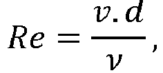
- the coolant pressure or the coolant flow in the coolant distribution system is set in such a way that a turbulent flow with Re> 2300 occurs in the coolant outlet adjusts.
- a continuous caster according to the invention comprises a mold for forming a strand, an oscillation device for moving the mold relative to the strand, a strand guide for supporting and guiding the strand and a cooling device according to the invention for secondary cooling of the strand with the advantages already mentioned above.
- the mold has a width adjustment for setting a width of the strand and the strand guide preferably has one G mandickenver ein to adjust a thickness of the strand.
- the oscillation device can advantageously generate movements of the mold, in particular oscillating movements of the mold, so that the strand does not adhere to an inner surface of the mold.
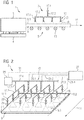
- Figure 1 shows schematically a section of a continuous caster 1 in a side view. Shown are a mold 3, an oscillation device 4 for moving the mold 3 relative to a strand 9, a strand guide 5 downstream of the mold 3 and a cooling device 7 of the continuous casting plant 1.
- the strand guide rollers 13 above the Line 9 and the line segments 17.1 and the coolant outlets 21 below the line 9 are not shown. It is known to the person skilled in the art that after exiting a mold in the secondary cooling, a strand is typically guided by strand guide rollers above and below the strand and the broad sides of the strand lying above and below are cooled.
- a metallic melt is fed to the mold 3, from which the metallic strand 9 is formed with the mold 3, which is guided with the strand guide 5 and transported along a transport direction 11.
- movements of the mold 4, in particular oscillating movements (the direction of movement is shown by an arrow) of the mold 4 are generated, so that the strand 9 does not adhere to an inner surface of the mold.
- the strand guide 5 has several strand guide rollers 13 to support the strand 9.
- the mold 3 has a width adjustment for setting a width of the strand 9, so that strands 9 of different widths can be produced with the mold 3.
- the strand guide 5 has a casting thickness adjustment for setting a thickness of the strand 9, so that strands 9 of different thicknesses can be produced with the strand guide 5.
- the cooling device 7 is used for secondary cooling of the strand 9 in the strand guide 5.
- the cooling device 7 comprises a coolant distribution system 15 with line segments 17.1 to 17.4 for conveying a coolant 19 and several coolant outlets 21 distributed over the strand guide 5 for outputting coolant 19 onto the strand 9.
- the coolant 19 is, for example, water.
- the continuous casting installation 1 shown is designed for what is known as horizontal continuous casting, in which the strand 9 is output horizontally from the mold 3 to the strand guide 5.
- the invention in particular a cooling device 7 according to the invention, is not limited to continuous casting plants 1 for horizontal continuous casting, but in particular also relates to continuous casting plants 1 which are designed for so-called vertical continuous casting, in which the strand 9 emerges vertically through a bottom opening of the mold 3 Mold 3 is issued to the strand guide 5 and the strand guide 5 is designed to be curved, so that the strand 9 is brought along the strand guide 5 from a horizontal to a vertical position.
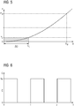
- FIG. 2 shows schematically a first embodiment of a cooling device 7 for secondary cooling of a strand 9 in a continuous casting plant 1 in a perspective view. Only a section of the strand 9 is shown, which is located in the area of the cooling device 7. Furthermore, of this section of the strand 9 and of the coolant distribution system 15 of the cooling device 7, only one area is shown, which extends over half a width of the strand 9 from a lateral strand edge 9.1 of the strand 9 to a central axis 9.2 running parallel to the transport direction 11 of the strand 9 extends.
- the coolant outlets 21 of the coolant distribution system 15 form several longitudinal rows of coolant outlets 21 arranged one behind the other along the transport direction 11 of the strand 9.
- the longitudinal rows are arranged next to one another transversely to the transport direction 11 of the strand 9, so that coolant outlets 21 of different longitudinal rows are arranged side by side across the transport direction 11 Form coolant outlets 21.
- the coolant distribution system 15 has eight longitudinal rows of coolant outlets 21 arranged next to one another, each longitudinal row having four coolant outlets 21.
- Alternative exemplary embodiments have one of eight different numbers of longitudinal rows of coolant outlets 21 arranged next to one another and / or at least one longitudinal row with one of four different numbers of coolant outlets 21.
- Each coolant outlet 21 forms an end of a line end segment 17.1 facing the strand 9 and running perpendicular to the strand surface 9.3.
- the coolant distribution system 15 has a line longitudinal segment 17.2 running parallel to the transport direction 11, which connects the line end segments 17.1 having these coolant outlets 21 to one another.
- the coolant distribution system 15 also has a transverse line segment 17.4 running transversely to the transport direction 11, which is connected to each longitudinal line segment 17.2 via an intermediate line segment 17.3 running perpendicular to the strand surface 9.3.
- Each line end segment 17.1 also has an outlet nozzle 33 with the coolant outlet 21 for outputting coolant 19, see in this regard Figure 3 .
- a switching valve 23 is arranged in each line end segment 17.1, with which a coolant supply of coolant 19 to the coolant outlet 21 of this line end segment 17.1 can be interrupted.
- Each switching valve 23 is designed as an on / off valve that has two operating states, the switching valve 23 releasing the coolant supply to the coolant outlet 21 in a first operating state and blocking the coolant supply to the coolant outlet 21 in the second operating state.
- a change in the operating state of a switching valve 23 is referred to here as switching the switching valve 23; Switching from the first to the second operating state is referred to as closing the switching valve 23 and switching from the second to the first operating state is referred to as opening the switching valve 23.
- Precisely one individual coolant flow Q, which is output from a coolant outlet 21, can therefore be switched on and off by each switching valve 23.
- the switching valves 23 are connected to a control unit 27 via control lines 25.1 to 25.4 and can be switched by the control unit 27.
- Each control line 25.1 to 25.4 connects the switching valves 23 of a longitudinal row of coolant outlets 21 with the control unit 27.
- the control lines 25.1 to 25.4 can run at least in sections in pipes of line segments 17.1 to 17.4, see the description of FIG Figure 3 below.
- the switching valves 23 are designed as pneumatically or electrically or electromagnetically or hydraulically switchable valves. Accordingly, the control lines 25.1 to 25.4 in the case of pneumatically switchable switching valves 23 are pneumatic compressed air lines, in the case of electrically or electromagnetically switchable switching valves 23 are electrical lines and in the case of hydraulically switchable switching valves 23 are hydraulic fluid lines.
- the control unit 27 is designed to switch the switching valves 23 in a manner described below.
- the cooling device 7 further comprises a pressure detection device 29 for detecting the coolant pressure P in the coolant distribution system 15.
- the signals detected by the pressure detection device 29 are fed to the control unit 27 via a pressure signal line 31.
- the control unit 27 evaluates these signals to analyze and check functions of the cooling device 7, for example to determine a degree of blockage of the coolant outlets 21.
- Figure 3 shows a perspective view of a line end segment 17.1.
- the line end segment 17.1 comprises a segment tube 35, a connecting flange 37, a switching valve 23 and an outlet nozzle 33.
- the connecting flange 37 is arranged at a first end of the segment tube 35 and can be connected to a line longitudinal segment 17.2.
- the switching valve 23 is arranged, which is attached to this end of the segment tube 35, for example by a pipe-valve screw connection 39, which is formed by an external thread on the outer surface of the segment tube 35 and a corresponding internal thread of the switching valve 23, can be screwed on.
- the outlet nozzle 33 has a nozzle tip 33.1 with a coolant outlet 21 and a nozzle base body 33.2.
- the nozzle body 33.2 is arranged on the switching valve 23 and can be screwed onto the switching valve 23, for example by a valve-nozzle screw connection 41, which is formed by an external thread on the outer surface of the switching valve 23 and a corresponding internal thread of the nozzle body 33.2.
- the nozzle tip 33.1 is arranged on the nozzle base body 33.2.
- the nozzle body 33.2 has an internal thread which corresponds to an external thread of the nozzle tip 33.1, so that the nozzle tip 33.1 can be detachably connected to the nozzle body 33.2.
- a jet profile of a coolant jet emitted by the outlet nozzle 33 can advantageously be changed by changing the nozzle tip 33.1.
- the segment tube 35 is used to guide coolant 19 to the coolant outlet 21 and to guide an end section of a control line 25.1 to 25.4 to the switching valve 23.
- the segment tube 35 has, for example, an outer tube and an inner tube running in the outer tube, with between the outer tube and the inner tube coolant 19 is guided and the inner tube forms or surrounds the end section of a control line 25.1 to 25.4.
- the connecting flange 37 has two flange openings 37.1, 37.2, a first flange opening 37.1 serving to supply coolant 19 into the segment tube 35 and the second flange opening 37.2 for guiding the control line 25.1 to 25.4 in the segment tube 35 is used.
- the connecting flange 37 also has a centering bolt 42 arranged between the flange openings 37.1, 37.2 in order to be able to assemble and align the line end segment 17.1 more easily.
- FIG 4 shows schematically a second embodiment of a cooling device 7 for secondary cooling of a strand 9 in a continuous casting plant 1 in a to Figure 2 analog perspective representation.
- This in Figure 4 The illustrated embodiment differs from that in the Figures 2 and 3 illustrated embodiment in that a switching valve 23 for a coolant outlet 21 is not arranged in each of the line end segments 17.1, but that for each longitudinal row of coolant outlets 21 only one switching valve 23 connected to the control unit 27 via a control line 25.1 to 25.4 is arranged in an intermediate line segment 17.3 is, so that a coolant supply from the line cross segment 17.4 to a line longitudinal segment 17.2 and all the line end segments 17.1 connected to it can be interrupted by each of these switching valves 23.
- a check valve 43 is arranged in order, after a coolant supply to the line end segment 17.1 has been blocked by the corresponding switching valve 23, an output of coolant 19, which is located in line segments 17.1 to 17.3 between the switching valve 23 and check valve 43, to the Strand 9 to prevent.
- the cooling device 7 of the in Figure 4 illustrated embodiment analogous to that in the Figures 2 and 3 illustrated embodiment formed.
- the switching valves 23 are like the switching valves 23 in the Figures 2 and 3 illustrated embodiment as on / off valves formed, which can be switched by the control unit 27 in a manner described in more detail below.
- the line end segments 17.1 in turn each have an outlet nozzle 33, the nozzle tip 33.1 of which is preferably designed to be exchangeable.
- the illustrated embodiment requires that in Figure 4
- the illustrated embodiment advantageously has fewer switching valves 23.
- a higher clock frequency of the pulse-width-modulated switching of the switching valves 23 (when using similar switching valves 23 in both embodiments) enables a more flexible control of the cooling with an individual control of the switching valves 23 and reduces the effects of a failure of an individual switching valve 23, since a such failure affects a smaller surface area of the strand 9.
- FIGS Figures 5 to 7 illustrate a cooling method for secondary cooling of a strand 9 in a continuous casting installation 1 with a cooling device 7, which is like one of the in FIGS Figures 2 to 4 illustrated embodiments is formed.
- FIG. 11 shows a diagram for a coolant pressure P as a function of a single coolant flow Q through an outlet nozzle 33 of the cooling device 7, which, like one of the in FIGS Figures 2 and 4th illustrated embodiments is formed.
- the individual coolant flow Q emitted from the outlet nozzle 33 through the coolant outlet 21 is in at least one flow range ⁇ Q for its mean value over time Q switched on and off by a pulse-width-modulated control of a switching valve 23 and thus itself pulse-width-modulated, see Figure 6 .
- this Current range ⁇ Q limited by a threshold current Q S , which corresponds to a threshold pressure P S.
- a maximum pressure P M and a corresponding maximum flow Q M for which the outlet nozzle 33 is designed, are also shown.
- the threshold flow Q S is specified in such a way that the coolant pressure P below the corresponding threshold pressure P S is no longer sufficient to achieve an intended jet profile of a coolant jet emitted by the outlet nozzle 33, in particular an intended opening angle of the coolant jet, to achieve a sufficiently large area to cover the strand surface 9.3 with the coolant jet.
- the individual coolant flows Q are output in the usual way, ie without pulse width modulation.
- the switching valves 23 of the individual coolant flows Q to be generated are opened and the coolant pressure P or a coolant flow in the coolant distribution system 15 is regulated by means of a control circuit 45 to a setpoint dependent on the individual coolant flows Q to be generated, see Figure 9 .
- Figure 6 shows a profile of a pulse-width-modulated individual coolant flow Q of an outlet nozzle 33 as a function of a time t.
- the pulse width modulation has a clock period of the period length T or a clock frequency 1 / T.
- the individual coolant flow Q has a constant, non-zero current pulse value Q P in a first half of each clock period and disappears in the second half of each clock period.
- the time average is accordingly Q of the individual coolant flow Q in this example is half as large as the current pulse value Q P.
- the pulse width modulation allows mean values with a current pulse value Q P that is greater than the threshold current Q S Q a single coolant flow Q can be realized, which is smaller than the threshold current Q S.
- individual coolant flows Q can be realized, their mean values over time Q are smaller than the threshold flow Q S and which nevertheless generate an intended jet profile of a coolant jet emitted by the outlet nozzle 33.
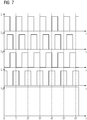
- Figure 7 shows diagrammatically temporal progressions of coolant flows Q 1 to Q 4 and a total coolant flow Q G , which are output by a cooling device 7 for secondary cooling of a strand 9 in a continuous casting plant 1 as a result of a pulse-width-modulated switching of the switching valves 23.
- the cooling device 7 is like one of the in the Figures 2 or 4th illustrated embodiments formed, wherein Figure 7 to simplify the representation of a cooling device 7 with only four longitudinal rows of coolant outlets 21 instead of as in the exemplary embodiments of FIG Figures 2 and 4th eight longitudinal rows refers to ( Figure 7 can also show temporal progressions of coolant flows Q 1 to Q 4 and a total coolant flow Q G in the Figures 2 or 4th represent the halves of the respective cooling devices 7 shown, the other halves (not shown) being controlled analogously).
- the coolant flows Q 1 to Q 4 are each output from all coolant outlets 21 of a longitudinal row together and are therefore each a sum of the individual coolant flows Q of the coolant outlets 21 of a longitudinal row, the individual coolant flows Q each being analogous to Figure 6 are pulse width modulated.
- the total coolant flow Q G is output from the coolant outlets 21 of all these longitudinal rows together and is the sum of the coolant flows Q 1 to Q 4 .
- the switching valves 23 are switched by the control unit 27 in a pulse-width-modulated manner with a clock period of the period length T or with a clock frequency 1 / T.
- the switching valves 23 for the various longitudinal rows of Coolant outlets 21 are switched with a time offset to one another, so that the total coolant flow Q G is constant over time.
- the switching valves 23 are switched in such a way that a first coolant flow Q 1 disappears during a second half of each cycle period, a second coolant flow Q 2 disappears during a first and last quarter of each cycle period, and a third coolant flow Q 3 disappears during the first half of each cycle period , a fourth coolant flow Q 4 disappears during a second and third quarter of each cycle period and the coolant flows Q 1 to Q 4 in the remaining times assume a constant, non-zero value for all longitudinal rows, which is half the total coolant flow Q G is.
- the total coolant flow Q G is regulated to a predetermined setpoint during the pulse width modulation.
- an actual value of the total coolant flow Q G is determined and a duty cycle D and the period length T of the pulse width modulation are regulated as a function of a deviation of the determined actual value from the setpoint.
- the duty cycle D of the pulse width modulation is understood to mean the ratio of a pulse duration during a clock period to the period length T. In the in the Figures 6 and 7th In the examples shown, the duty cycle D is for example 50% in each case.
- coolant pressures P in line segments 17.1 to 17.4, via which individual coolant flows Q are output are recorded and the individual coolant flows Q output in each case are deduced from this by means of current-pressure characteristics.
- the actual value of the total coolant flow Q G is then formed as the sum of these individual coolant flows Q, each multiplied by the respective duty cycle D of the pulse width modulation.
- Figure 8 shows the duty cycle D of the pulse width modulation of an individual coolant flow Q as a function of the mean value Q of the individual coolant flow Q in the flow range ⁇ Q.
- the duty cycle end value D m assumes the value 1, for example. If the coolant pressure P in the coolant distribution system 15 is set to a higher pressure value, the duty cycle end value D m is correspondingly smaller.
- a selection of coolant outlets 21, through which individual coolant flows Q are output, is also made as a function of a width of the strand 9. Coolant outlets 21, which are not required to cool the strand 9 because they are located next to the strand surface 9.3, for example only release blow-out air in a pulse pause or a short water pulse to prevent these coolant outlets 21 from clogging.
- Figure 9 shows a control circuit 45 for regulating a coolant pressure P or coolant flow in the coolant distribution system 15 in order to generate individual coolant flows Q which are greater than the threshold flow Q S.
- the controlled variable R of the control loop 45 is therefore the coolant pressure P or coolant flow in the coolant distribution system 15.
- a reference variable S of the control loop 45 is accordingly a setpoint value of the coolant pressure P or coolant flow in the which depends on the individual coolant flows Q Coolant distribution system 15.
- the control circuit 45 comprises a controller 47, a controlled system 49 and a measuring element 51.
- the controller 47 is a pump for the direct generation of a coolant pressure P or coolant flow in the coolant distribution system 15, or a pump with a downstream pressure or flow controller for Reduction of a coolant pressure P or coolant flow generated by the pump in the coolant distribution system 15.
- the controlled system 49 is the coolant distribution system 15.
- the measuring element 51 is a pressure detection device 29 for detecting the coolant pressure P or a flow detection device for detecting a coolant flow in the coolant distribution system 15
- Controlled variable R, a system deviation E of the controlled variable R from the reference variable S is formed.
- the controller 47 generates a manipulated variable U that is dependent on the control deviation E in order to reduce the control deviation B.
Description
- Die Erfindung betrifft eine Kühlungsvorrichtung und ein Kühlungsverfahren zur Sekundärkühlung eines Strangs in einer Strangführung einer Stranggießanlage.
- Beim Stranggießen in einer Stranggießanlage wird in einer Kokille ein metallischer Strang gebildet und anschließend in einer Strangführung geführt und dabei weiter abgekühlt. Die Abkühlung des Strangs in der Strangführung wird als Sekundärkühlung bezeichnet, während eine Kühlung des Strangs in der Kokille Primärkühlung genannt wird. Bei der Sekundärkühlung wird mittels einer Kühlungsvorrichtung auf den Strang in der Regel ein Kühlmittel, beispielsweise Wasser oder ein Wasser-Luft-Gemisch, aufgebracht.
- Aus der
EP 2 527 061 A1 ist eine Sekundärkühleinrichtung und ein Kühlungsverfahren zur Sekundärkühlung eines Strangs in einer Stranggießanlage bekannt, bei der die Kühlleistung durch eine PWM Ansteuerung des Tastgrads eines Schaltventils eingestellt wird. Wie das Verhältnis zwischen dem maximalen und dem minimalen Kühlmitteleinzelstrom erhöht und zusätzlich auch bei kleinen Kühlmitteleinzelströmen die Ausbildung eines geeigneten Strahlprofils (insbesondere des Öffnungswinkels des Kühlmittelstrahls aus dem Kühlmittelauslass) erreicht werden kann, geht aus der Schrift nicht hervor. - Der Erfindung liegt die Aufgabe zugrunde, eine verbesserte Kühlungsvorrichtung und ein verbessertes Kühlungsverfahren zur Sekundärkühlung eines Strangs in einer Stranggießanlage anzugeben. Insbesondere soll das Verhältnis zwischen der maximal aufbringbaren Kühlmittelmenge und der minimal aufbringbaren Kühlmittelmenge erhöht werden.
- Die Aufgabe wird erfindungsgemäß hinsichtlich der Kühlungsvorrichtung durch die Merkmale des Anspruchs 1 und hinsichtlich des Kühlungsverfahrens durch die Merkmale des Anspruchs 10 gelöst.
- Vorteilhafte Ausgestaltungen der Erfindung sind Gegenstand der Unteransprüche.
- Eine erfindungsgemäße Kühlungsvorrichtung zur Sekundärkühlung eines Strangs in einer Strangführung einer Stranggießanlage umfasst ein Kühlmittelverteilungssystem mit Leitungssegmenten zur Leitung eines Kühlmittels und mehreren über die Strangführung verteilten Kühlmittelauslässen zur Ausgabe jeweils eines Kühlmitteleinzelstroms auf den Strang, wenigstens ein Schaltventil, mit dem wenigstens ein Kühlmitteleinzelstrom ein- und abschaltbar ist, eine Steuereinheit, die zu einer Pulsweitenmodulation wenigstens eines Kühlmitteleinzelstroms in einem Strombereich für einen zeitlichen Mittelwert des Kühlmitteleinzelstroms durch eine pulsweitenmodulierte Ansteuerung eines Schaltventils ausgebildet ist und einen Regelkreis zur Regelung eines Kühlmitteldrucks oder Kühlmittelstroms in dem Kühlmittelverteilungssystem.
- Die Kühlungsvorrichtung ermöglicht also, einen in einer Stranggießanlage hergestellten Strang durch pulsweitenmodulierte Kühlmitteleinzelströme zu kühlen, die von über eine Strangführung verteilten Kühlmittelauslässen ausgegeben werden. Dabei wird die Pulsweitenmodulation in einem Strombereich für einen zeitlichen Mittelwert eines Kühlmitteleinzelstroms realisiert. Bei der Pulsweitenmodulation eines Kühlmitteleinzelstroms verschwindet der Kühlmitteleinzelstrom während eines Teils jeder Taktperiode der Pulsweitenmodulation und nimmt während des anderen Teils jeder Taktperiode einen konstanten, von Null verschiedenen Strompulswert an. Dieser Strompulswert ist daher größer als der zeitliche Mittelwert des pulsweitenmodulierten Kühlmitteleinzelstroms.
- Dies ist insbesondere vorteilhaft, wenn der einzustellende zeitliche Mittelwert so klein ist, dass ein ungepulster, d. h. zeitlich konstanter Kühlmitteleinzelstrom, der diesen Mittelwert erzeugen würde, ein vorgesehenes Strahlprofil eines von dem Kühlmitteleinzelstrom erzeugten Kühlmittelstrahls aufgrund eines zu geringen Kühlmitteldrucks nicht realisieren kann. Das Strahlprofil, insbesondere ein Öffnungswinkel des Kühlmittelstrahls, ist nämlich wesentlich für die Größe des von dem Kühlmittelstrahl benetzten Bereiches des Strangs und damit für die Kühlwirkung des Kühlmittelstrahls. Zur Erzeugung eines vorgesehenen Strahlprofils werden die Kühlmittelauslässe vorzugsweise von entsprechenden Auslassdüsen gebildet. Die Größe des Kühlmitteleinzelstroms korrespondiert zu einem Kühlmitteldruck, der bei zu kleinem Kühlmitteleinzelstrom nicht zur Erzeugung des vorgesehenen Strahlprofils ausreicht.
- Daher wird eine Pulsweitenmodulation eines Kühlmitteleinzelstroms vorzugsweise in einem Strombereich durchgeführt, der von einem Schwellenstrom begrenzt wird, bei dem der Kühlmitteldruck nicht mehr ausreichen würde, bei einem vollständig geöffneten Schaltventil ein vorgesehenes Strahlprofil eines von dem Kühlmitteleinzelstrom erzeugten Kühlmittelstrahls zu realisieren. Durch die Pulsweitenmodulation des Kühlmitteleinzelstroms können mit Strompulswerten, die größer als der Schwellenstrom sind, Mittelwerte des Kühlmitteleinzelstroms realisiert werden, die kleiner als der Schwellenstrom sind. Mit anderen Worten können Kühlmitteleinzelströme realisiert werden, deren zeitliche Mittelwerte kleiner als der Schwellenstrom sind und die dennoch ein vorgesehenes Strahlprofil des Kühlmittelstrahls erzeugen, da die Strompulswerte größer als der Schwellenstrom sind.
- Durch die Pulsweitenmodulation insbesondere von Kühlmitteleinzelströmen, deren zeitliche Mittelwerte kleiner als der Schwellenstrom sind, können daher Kühlmittelstrahlen eines vorgesehenen Strahlprofils über ein größeres Stromwerteintervall als bei einer ausschließlichen Verwendung ungepulster Kühlmitteleinzelströme realisiert werden, d. h. die Kühlungsvorrichtung kann in einem größeren Betriebsfenster, das durch dieses Stromwerteintervall definiert ist, betreiben werden.
- Oberhalb des Schwellenstroms können ungepulste Kühlmitteleinzelströme durch Regelung eines Kühlmitteldrucks oder Kühlmittelstroms in dem Kühlmittelverteilungssystem mit dem Regelkreis erzeugt werden.
- Die Erfindung ermöglicht auch, das Betriebsfenster bereits existierender herkömmlicher Kühlungsvorrichtungen in relativ einfacher und kostengünstiger Weise zu erweitern, d. h. diese Kühlungsvorrichtungen derart umzugestalten, dass Kühlmittelstrahlen eines vorgesehenen Strahlprofils über ein größeres Stromwerteintervall der Kühlmitteleinzelströme realisiert werden können. Dazu brauchen lediglich Schaltventile und eine mit den Schaltventilen verbundene Steuereinheit zur pulsweitenmodulierten Ein- und Abschaltung von Kühlmitteleinzelströmen eingebaut werden, beispielsweise indem existierende herkömmliche Leitungssegmente durch Leitungssegmente mit Schaltventilen ersetzt und die Schaltventile mit der Steuereinheit über (im Vergleich zu Kühlmittelleitungen kostengünstige) Steuerleitungen verbunden werden, ohne das Kühlmittelverteilungssystem als Ganzes aufwändig zu verändern oder zu ersetzen. Eine derartige Umgestaltung kann zudem vorteilhaft schrittweise erfolgen, so dass der Betrieb der Stranggießanlage jeweils nur für relativ kurze Umbauzeiten unterbrochen werden muss.
- Als Schaltventile eignen sich beispielsweise pneumatisch oder elektrisch oder elektromagnetisch oder hydraulisch schaltbare Ventile. Derartig ausgebildete Schaltventile sind vorteilhaft kommerziell verfügbar und ermöglichen eine kostengünstige Realisierung ein- und abschaltbarer Kühlmitteleinzelströme.
- Wie oben bereits erwähnt wurde, werden die Kühlmittelauslässe vorzugsweise jeweils von einer Auslassdüse gebildet. Eine Weitergestaltung dieser Ausgestaltung der Erfindung sieht vor, dass wenigstens eine Auslassdüse eine austauschbare Düsenspitze aufweist.
- Durch von Auslassdüsen gebildete Kühlmittelauslässe können vorteilhaft zur Strangkühlung besonders geeignete Strahlprofile der von den Kühlmittelauslässen abgegebenen Kühlmittelstrahlen erzeugt werden. Auslassdüsen mit austauschbaren Düsenspitzen ermöglichen vorteilhaft, diese Strahlprofile erforderlichenfalls in einfacher Weise durch den Austausch der Düsenspitzen zu verändern.
- Weitere Ausgestaltungen der Erfindungen sehen vor, dass entweder mit jedem Schaltventil genau ein Kühlmitteleinzelstrom oder mit wenigstens einem Schaltventil mehrere Kühlmitteleinzelströme ein- und abschaltbar sind.
- Schaltventile, mit denen jeweils genau ein Kühlmitteleinzelstrom ein- und abschaltbar ist, sind schneller schaltbar als gleichartige Schaltventile für jeweils mehrere Kühlmitteleinzelströme und ermöglichen dadurch eine höhere Taktfrequenz der Pulsweitenmodulation der Kühlmitteleinzelströme. Ferner ermöglichen sie durch eine individuelle Ansteuerung der Schaltventile eine flexiblere Steuerung der Kühlung und reduzieren die Auswirkungen eines Ausfalls eines einzelnen Schaltventils. Schaltventile für jeweils mehrere Kühlmitteleinzelströme reduzieren dagegen vorteilhaft die Anzahl der benötigten Schaltventile und damit die Kosten und den Aufwand zur Realisierung der Kühlungsvorrichtung gegenüber Schaltventilen für jeweils einen Kühlmitteleinzelstrom. Es hängt daher von den jeweiligen Anforderungen an die Kühlungsvorrichtung ab, ob Schaltventile für jeweils einen Kühlmitteleinzelstrom oder mehrere Kühlmitteleinzelströme vorteilhafter sind.
- Weitere Ausgestaltungen der Erfindung sehen wenigstens eine Längsreihe mehrerer entlang einer Transportrichtung des Strangs hintereinander angeordneter Kühlmittelauslässe und/oder wenigstens eine Querreihe mehrerer quer zu einer Transportrichtung des Strangs nebeneinander angeordneter Kühlmittelauslässe vor.
- Diese Ausgestaltungen ermöglichen vorteilhaft eine über einen Abschnitt einer Strangführung gleichmäßig verteilte Sekundärkühlung eines Strangs, insbesondere wenn die Kühlungsvorrichtung jeweils mehrere Längs- und Querreihen von Kühlmittelauslässen aufweist.
- Eine weitere Ausgestaltung der Erfindung sieht eine Druckerfassungsvorrichtung zur Erfassung eines Kühlmitteldrucks oder einen Durchflussmesser zur Erfassung eines Kühlmittelstroms in dem Kühlmittelverteilungssystem vor.
- Eine derartige Druckerfassungsvorrichtung ermöglicht vorteilhaft eine Analyse und Überprüfung von Funktionen der Kühlungsvorrichtung, beispielsweise die Ermittlung eines Verstopfungsgrades von Kühlmittelauslässen, durch eine Auswertung der von der Druckerfassungsvorrichtung erfassten Signale. Außerdem kann ein Ist-Wert eines Kühlmitteldrucks oder Kühlmittelstroms zur Regelung des Kühlmitteldrucks oder Kühlmittelstroms im Kühlmittelverteilungssystem erfasst werden.
- Bei einem erfindungsgemäßen Kühlungsverfahren zur Sekundärkühlung eines Strangs in einer Strangführung einer Stranggießanlage durch eine erfindungsgemäße Kühlungsvorrichtung werden ein Schwellenstrom Qs für zeitliche Mittelwerte
Q von zumindest einem Kühlmitteleinzelstrom und ein unterhalb des Schwellenstroms oder gleich dem Schwellenstrom liegender Strombereich ΔQ vorgegeben. Für den Strombereich ΔQgilt Δ Q = [0, QS ]. In dem Strombereich liegende zeitliche Mittelwerte von Kühlmitteleinzelströmen mit 0 ≤Q ≤ QS werden erzeugt, indem ein Kühlmitteldruck in dem Kühlmittelverteilungssystem auf einen konstanten Druckwert eingestellt wird und jeder Kühlmitteleinzelstrom durch eine pulsweitenmodulierte Ansteuerung eines Schaltventils mit einem von dem zu erzeugenden Mittelwert abhängigen Tastgrad pulsweitenmoduliert wird. Außerhalb des Strombereichs liegende zeitliche Mittelwerte von Kühlmitteleinzelströmen mitQ > QS werden erzeugt, indem die Schaltventile dieser Kühlmitteleinzelströme geöffnet werden und der Kühlmitteldruck oder ein Kühlmittelstrom in dem Kühlmittelverteilungssystem mit dem Regelkreis auf einen von den zu erzeugenden Kühlmitteleinzelströmen abhängigen Sollwert geregelt wird. - Mit dem Kühlungsverfahren wird die oben bereits erwähnte vorteilhafte Vergrößerung des Betriebsfensters der Kühlungsvorrichtung gegenüber einer Verwendung ungepulster Kühlmitteleinzelströme realisiert.
- Eine Ausgestaltung des Kühlungsverfahrens sieht vor, dass mehrere Kühlmitteleinzelströme in dem Strombereich für ihre zeitlichen Mittelwerte derart pulsweitenmoduliert werden, dass ein von allen diesen Kühlmitteleinzelströmen zusammen gebildeter Kühlmittelgesamtstrom zeitlich konstant ist.
- Diese Ausgestaltung der Erfindung sieht also eine zeitversetzte Ein- und Abschaltung von Kühlmitteleinzelströmen bei deren Pulsweitenmodulation vor, um einen von allen diesen Kühlmitteleinzelströmen gebildeten Kühlmittelgesamtstrom zeitlich konstant zu halten. Dadurch kann vorteilhaft ein gleichmäßiger von der Kühlungsvorrichtung auf den Strang abgegebener Kühlmittelgesamtstrom erzeugt werden, auch wenn die von den einzelnen Kühlmittelauslässen abgegebenen Kühlmitteleinzelströme jeweils pulsweitenmoduliert werden.
- Eine weitere Ausgestaltung des Kühlungsverfahrens sieht vor, dass mehrere Kühlmitteleinzelströme in dem Strombereich für ihre zeitlichen Mittelwerte derart pulsweitenmoduliert werden, dass ein von allen diesen Kühlmitteleinzelströmen zusammen gebildeter Kühlmittelgesamtstrom auf einen Sollwert geregelt wird. Dabei wird ein Istwert des Kühlmittelgesamtstroms ermittelt und ein Tastgrad und eine Periodenlänge einer Taktperiode der Pulsweitenmodulation werden in Abhängigkeit von einer Abweichung des ermittelten Istwertes von dem Sollwert geregelt.
- Diese Ausgestaltung der Erfindung ermöglicht vorteilhaft eine Regelung eines von mehreren Kühlmittelauslässen ausgegebenen Kühlmittelgesamtstroms auf einen vorgebbaren Sollwert durch Einstellen des Tastgrades und der Periodenlänge der Pulsweitenmodulation der Kühlmitteleinzelströme. Um den Istwert des Kühlmittelgesamtstroms zu ermitteln, werden beispielsweise jeweils Kühlmitteldrücke in Leitungssegmenten, über die Kühlmitteleinzelströme ausgegeben werden, erfasst und daraus mittels Strom-Druck-Kennlinien auf die jeweils ausgegebenen Kühlmitteleinzelströme geschlossen. Der Istwert des Kühlmittelgesamtstroms wird dann als Summe dieser Kühlmitteleinzelströme, jeweils multipliziert mit dem jeweiligen Tastgrad der Pulsweitenmodulation, gebildet.
- Eine weitere Ausgestaltung des Kühlungsverfahrens sieht vor, dass eine Auswahl von Kühlmittelauslässen, durch die Kühlmitteleinzelströme ausgegeben werden, in Abhängigkeit von einer Breite des Strangs getroffen wird.
- Dadurch kann die Kühlung eines Strangs vorteilhaft seiner Breite angepasst werden. Durch Kühlmittelauslässe, die zur Kühlung eines Strangs nicht benötigt werden, da sie sich neben der Strangoberfläche befinden, werden dabei beispielsweise nur jeweils Ausblasluft in einer Pulspause oder ein kurzer Wasserpuls abgegeben, um ein Verstopfen dieser Kühlmittelauslässe zu verhindern.
- Eine weitere Ausgestaltung der Erfindung sieht vor, dass ein Kühlmitteldruck in dem Kühlmittelverteilungssystem erfasst und zur Ermittlung eines Verstopfungsgrades wenigstens eines Kühlmittelauslasses ausgewertet wird.
- Dadurch kann vorteilhaft eine Fehlfunktion der Kühlungsvorrichtung durch eine Verstopfung von Kühlmittelauslässen, die eine mangelnde Kühlung des Strangs zur Folge hat, erkannt werden.
- Um bei verschiedenen Gießgeschwindigkeiten denselben Bereich des Strangs durch einen Kühlmittelauslass zu beaufschlagen, ist es vorteilhaft, wenn die Taktfrequenz f = 1/T proportional zur Gießgeschwindigkeit der Stranggießanlage eingestellt wird. Beispielsweise bewegt sich ein Strang, der mit einer Gießgeschwindigkeit von 0,05 m/s die Sekundärkühlung durchläuft, und durch einen Kühlmittelauslass bei einer Taktfrequenz von 0,5 Hz und einem Tastgrad D von 50% gekühlt wird, während eines einzelnen Kühlzyklusses um 0,05 m weiter. Wird nun die Gießgeschwindigkeit auf 0,1 m/s verdoppelt und der Tastgrad D bei 50% konstant gehalten, so muss die Taktfrequenz auf 1 Hz ebenfalls verdoppelt werden, sodass sich der Strang während eines einzelnen Kühlzyklusses wiederum um 0,05 m weiterbewegt.
- Außerdem hat es sich als günstig erwiesen, wenn der Tastgrad D bei unterschiedlichen Gießgeschwindigkeiten konstant gehalten wird, jedoch der Kühlmitteleinzelstrom (Q) durch einen Kühlmittelauslasses (21) proportional zur Gießgeschwindigkeit eingestellt wird. Dies führt dazu, dass bei einer Verdoppelung der Gießgeschwindigkeit bei gleicher Taktfrequenz und gleichem Tastgrad der Kühlmmittelstrom verdoppelt werden muss um im selben Kühlzyklus dieselbe Kühlmittelmenge auszubringen.
- Wird hingegen nicht ein Kühlmitteleinzelstrom sondern der Kühlmitteldruck eingestellt, so ist es günstig, wenn wiederum der Tastgrad D bei unterschiedlichen Gießgeschwindigkeiten konstant gehalten und der Kühlmitteldruck (P) proportional zum Quadrat der Gießgeschwindigkeit eingestellt wird. Dies führt dazu, dass bei einer Verdoppelung der Gießgeschwindigkeit bei gleicher Taktfrequenz und gleichem Tastgrad der Kühlmitteldruck vervierfacht werden muss um im selben Kühlzyklus dieselbe Kühlmittelmenge auszubringen.
- Um auch bei unterschiedlichen Kühlmitteldrücken bzw. -strömen ein gleichmäßiges Strahlprofil, idealerweise einen konstanten Öffnungswinkel, eines Kühlmittelstrahls zu erreichen, ist es vorteilhaft, wenn der Kühlmitteldruck oder der Kühlmittelstrom im Kühlmittelverteilungssystem derart eingestellt wird, dass sich im Kühlmittelauslass eine turbulente Strömung mit Re > 2300 einstellt.
- Die Reynoldszahl Re (z.B. de.wikipedia.org/wiki/ReynoldsZahl)
- Der Schwellenwert QS wird vorzugsweise derart gewählt, dass sich für jeden Kühlmitteleinzelstrom durch den jeweiligen Kühlmittelauslass eine turbulente Strömung einstellt. Eine erfindungsgemäße Stranggießanlage umfasst eine Kokille zur Bildung eines Strangs, eine Osszilationseinrichtung zum Bewegen der Kokille gegenüber des Strangs, eine Strangführung zum Stützen und Führung des Strangs und eine erfindungsgemäße Kühlungsvorrichtung zur Sekundärkühlung des Strangs mit den oben bereits genannten Vorteilen. Dabei weist die Kokille eine Breitenverstellung zur Einstellung einer Breite des Strangs auf und die Strangführung weist vorzugsweise eine Gießdickenverstellung zur Einstellung einer Dicke des Strangs auf. Dadurch können vorteilhaft Stränge verschiedener Breiten und Dicken erzeugt werden. Durch die Osszilationseinrichtung können vorteilhaft Bewegungen der Kokille, insbesondere oszillierende Bewegungen der Kokille, erzeugt werden, damit der Strang nicht an einer Innenoberfläche der Kokille anhaftet.
- Die oben beschriebenen Eigenschaften, Merkmale und Vorteile dieser Erfindung sowie die Art und Weise, wie diese erreicht werden, werden klarer und deutlicher verständlich im Zusammenhang mit der folgenden Beschreibung von Ausführungsbeispielen, die im Zusammenhang mit den Zeichnungen näher erläutert werden. Dabei zeigen:
-
FIG 1 schematisch einen Ausschnitt einer Stranggießanlage in einer Seitenansicht, -
FIG 2 schematisch ein erstes Ausführungsbeispiel einer Kühlungsvorrichtung zur Sekundärkühlung eines Strangs in einer Stranggießanlage in einer perspektivischen Darstellung, -
FIG 3 eine perspektivische Darstellung eines Leitungsendsegments einer Kühlungsvorrichtung zur Sekundärkühlung eines Strangs in einer Stranggießanlage, -
FIG 4 schematisch ein zweites Ausführungsbeispiel einer Kühlungsvorrichtung zur Sekundärkühlung eines Strangs in einer Stranggießanlage in einer perspektivischen Darstellung, -
FIG 5 ein Diagramm eines Kühlmitteldrucks in Abhängigkeit von einem Kühlmitteleinzelstrom einer Auslassdüse, -
FIG 6 ein Diagramm eines zeitlichen Verlaufs eines pulsweitenmodulierten Kühlmitteleinzelstroms einer Auslassdüse, -
FIG 7 diagrammatisch zeitliche Verläufe von pulsweitenmodulierten Kühlmittelströmen, die von einer Kühlungsvorrichtung zur Sekundärkühlung eines Strangs in einer Stranggießanlage ausgegeben werden, -
FIG 8 einen Tastgrad D einer Pulsweitenmodulation eines Kühlmitteleinzelstroms in Abhängigkeit von dem Mittelwert des Kühlmitteleinzelstroms, und -
FIG 9 einen Regelkreis zur Regelung eines Kühlmitteldrucks oder Kühlmittelstroms in einem Kühlmittelverteilungssystem. - Einander entsprechende Teile sind in allen Figuren mit den gleichen Bezugszeichen versehen.
-
Figur 1 zeigt schematisch einen Ausschnitt einer Stranggießanlage 1 in einer Seitenansicht. Dargestellt sind eine Kokille 3, eine Oszillationseinrichtung 4 zum Bewegen der Kokille 3 gegenüber eines Strangs 9, eine der Kokille 3 nachgeordnete Strangführung 5 und eine Kühlungsvorrichtung 7 der Stranggießanlage 1. Um die Komplexität der Figur nicht unnötig zu erhöhen, wurden die Strangführungsrollen 13 oberhalb des Strangs 9 sowie die Leitungssegmente 17.1 und die Kühlmittelauslässe 21 unterhalb des Strangs 9 nicht dargestellt. Dem Fachmann ist bekannt, dass ein Strang nach dem Austritt aus einer Kokille in der Sekundärkühlung typischerweise durch Strangführungsrollen ober- und unterhalb des Strangs geführt wird sowie die oben- und untenliegenden Breitseiten des Strangs gekühlt werden. - Der Kokille 3 wird eine metallische Schmelze zugeführt, aus der mit der Kokille 3 der metallische Strang 9 gebildet wird, der mit der Strangführung 5 geführt und entlang einer Transportrichtung 11 transportiert wird. Mit der Osszilationseinrichtung 4 werden Bewegungen der Kokille 4, insbesondere oszillierende Bewegungen (die Bewegungsrichtung ist durch einen Pfeil dargestellt) der Kokille 4, erzeugt, damit der Strang 9 nicht an einer Innenoberfläche der Kokille anhaftet. Die Strangführung 5 weist mehrere Strangführungsrollen 13 zur Stützung des Strangs 9 auf.
- Die Kokille 3 weist eine Breitenverstellung zur Einstellung einer Breite des Strangs 9 aufweist, so dass mit der Kokille 3 Stränge 9 unterschiedlicher Breiten erzeugbar sind. Die Strangführung 5 weist eine Gießdickenverstellung zur Einstellung einer Dicke des Strangs 9 auf, so dass mit der Strangführung 5 Stränge 9 verschiedener Dicken erzeugbar sind.
- Die Kühlungsvorrichtung 7 dient der Sekundärkühlung des Strangs 9 in der Strangführung 5. Die Kühlungsvorrichtung 7 umfasst ein Kühlmittelverteilungssystem 15 mit Leitungssegmenten 17.1 bis 17.4 zur Leitung eines Kühlmittels 19 und mehreren über die Strangführung 5 verteilten Kühlmittelauslässen 21 zur Ausgabe von Kühlmittel 19 auf den Strang 9. Anhand der
Figuren 2 bis 4 werden unten verschiedene Ausführungsbeispiele von Kühlungsvorrichtungen 7 näher beschrieben. Das Kühlmittel 19 ist beispielsweise Wasser. - Die in
Figur 1 dargestellte Stranggießanlage 1 ist zum so genannten horizontalen Stranggießen ausgebildet, bei dem der Strang 9 horizontal aus der Kokille 3 zu der Strangführung 5 ausgegeben wird. Die Erfindung, insbesondere eine erfindungsgemäße Kühlungsvorrichtung 7, ist jedoch nicht auf Stranggießanlagen 1 zum horizontalen Stranggießen beschränkt, sondern betrifft insbesondere auch Stranggießanlagen 1, die zum so genannten vertikalen Stranggießen ausgebildet sind, bei dem der Strang 9 vertikal durch eine Bodenöffnung der Kokille 3 aus der Kokille 3 zu der Strangführung 5 ausgegeben wird und die Strangführung 5 gebogen ausgeführt ist, so dass der Strang 9 entlang der Strangführung 5 von einer horizontalen in eine vertikale Lage gebracht wird. -
Figur 2 zeigt schematisch ein erstes Ausführungsbeispiel einer Kühlungsvorrichtung 7 zur Sekundärkühlung eines Strangs 9 in einer Stranggießanlage 1 in einer perspektivischen Darstellung. Dabei ist nur ein Abschnitt des Strangs 9 dargestellt, der sich im Bereich der Kühlungsvorrichtung 7 befindet. Ferner ist von diesem Abschnitt des Strangs 9 und von dem Kühlmittelverteilungssystem 15 der Kühlungsvorrichtung 7 nur jeweils ein Bereich dargestellt, der sich über eine Hälfte einer Breite des Strangs 9 von einem seitlichen Strangrand 9.1 des Strangs 9 bis zu einer parallel zur Transportrichtung 11 verlaufenden Mittelachse 9.2 des Strangs 9 erstreckt. Über die andere Hälfte der Breite des Strangs 9 erstreckt sich ein weiterer Bereich des Kühlmittelverteilungssystems 15, der ebenso ausgebildet ist wie der inFigur 2 dargestellte Bereich, wobei diese beiden Bereiche spiegelsymmetrisch sind bezüglich einer Spiegelung an einer Spiegelebene, die die Mittelachse 9.2 enthält und senkrecht zu einer Strangoberfläche 9.3 des Strangs 9 ist. - Die Kühlmittelauslässe 21 des Kühlmittelverteilungssystems 15 bilden mehrere Längsreihen entlang der Transportrichtung 11 des Strangs 9 hintereinander angeordneter Kühlmittelauslässe 21. Dabei sind die Längsreihen quer zu der Transportrichtung 11 des Strangs 9 nebeneinander angeordnet, so dass Kühlmittelauslässe 21 verschiedener Längsreihen Querreihen quer zu der Transportrichtung 11 nebeneinander angeordneter Kühlmittelauslässe 21 bilden.
- Im in
Figur 2 dargestellten Ausführungsbeispiel weist das Kühlmittelverteilungssystem 15 acht nebeneinander angeordnete Längsreihen von Kühlmittelauslässen 21 auf, wobei jede Längsreihe vier Kühlmittelauslässe 21 aufweist. Alternative Ausführungsbeispiele weisen eine von acht verschiedene Anzahl nebeneinander angeordneter Längsreihen von Kühlmittelauslässen 21 oder/und wenigstens eine Längsreihe mit einer von Vier verschiedenen Anzahl von Kühlmittelauslässen 21 auf. - Jeder Kühlmittelauslass 21 bildet ein dem Strang 9 zugewandtes Ende eines Leitungsendsegments 17.1, das senkrecht zu der Strangoberfläche 9.3 verläuft. Für jede Längsreihe von Kühlmittelauslässen 21 weist das Kühlmittelverteilungssystem 15 ein parallel zur Transportrichtung 11 verlaufendes Leitungslängssegment 17.2 auf, das die diese Kühlmittelauslässe 21 aufweisenden Leitungsendsegmente 17.1 miteinander verbindet. Das Kühlmittelverteilungssystem 15 weist ferner ein quer zur Transportrichtung 11 verlaufendes Leitungsquersegment 17.4 auf, das mit jedem Leitungslängssegment 17.2 über jeweils ein senkrecht zur Strangoberfläche 9.3 verlaufendes Leitungszwischensegment 17.3 verbunden ist. Jedes Leitungsendsegment 17.1 weist ferner zur Ausgabe von Kühlmittel 19 eine Auslassdüse 33 mit dem Kühlmittelauslass 21 auf, siehe dazu
Figur 3 . - In jedem Leitungsendsegment 17.1 ist ein Schaltventil 23 angeordnet, mit dem eine Kühlmittelzufuhr von Kühlmittel 19 zu dem Kühlmittelauslass 21 dieses Leitungsendsegments 17.1 unterbrechbar ist. Jedes Schaltventil 23 ist dabei als ein Auf-/Zu-Ventil ausgebildet, das zwei Betriebszustände aufweist, wobei das Schaltventil 23 in einem ersten Betriebszustand die Kühlmittelzufuhr zu dem Kühlmittelauslass 21 freigibt und in dem zweiten Betriebszustand die Kühlmittelzufuhr zu dem Kühlmittelauslass 21 sperrt. Eine Veränderung des Betriebszustands eines Schaltventils 23 wird hier als Schalten des Schaltventils 23 bezeichnet; ein Schalten von dem ersten in den zweiten Betriebszustand wird als Schließen des Schaltventils 23 bezeichnet und ein Schalten von dem zweiten in den ersten Betriebszustand wird als Öffnen des Schaltventils 23 bezeichnet. Durch jedes Schaltventil 23 ist also genau ein Kühlmitteleinzelstrom Q ein- und abschaltbar, der von einem Kühlmittelauslass 21 ausgegeben wird.
- Die Schaltventile 23 sind über Steuerleitungen 25.1 bis 25.4 mit einer Steuereinheit 27 verbunden und durch die Steuereinheit 27 schaltbar. Dabei verbindet jede Steuerleitung 25.1 bis 25.4 die Schaltventile 23 einer Längsreihe von Kühlmittelauslässen 21 mit der Steuereinheit 27. Die Steuerleitungen 25.1 bis 25.4 können zumindest abschnittsweise in Rohren von Leitungssegmenten 17.1 bis 17.4 verlaufen, vgl. die Beschreibung von
Figur 3 unten. - Die Schaltventile 23 sind als pneumatisch oder elektrisch oder elektromagnetisch oder hydraulisch schaltbare Ventile ausgebildet. Entsprechend sind die Steuerleitungen 25.1 bis 25.4 im Falle pneumatisch schaltbarer Schaltventile 23 pneumatische Druckluftleitungen, im Falle elektrisch oder elektromagnetisch schaltbarer Schaltventile 23 elektrische Leitungen und im Falle hydraulisch schaltbarer Schaltventile 23 Hydraulikflüssigkeitsleitungen.
- Die Steuereinheit 27 ist dazu ausgebildet, die Schaltventile 23 in einer unten beschriebenen Weise zu schalten.
- Die Kühlungsvorrichtung 7 umfasst ferner eine Druckerfassungsvorrichtung 29 zur Erfassung des Kühlmitteldrucks P in dem Kühlmittelverteilungssystem 15. Die von der Druckerfassungsvorrichtung 29 erfassten Signale werden über eine Drucksignalleitung 31 der Steuereinheit 27 zugeführt. Die Steuereinheit 27 wertet diese Signale zu einer Analyse und Überprüfung von Funktionen der Kühlungsvorrichtung 7, beispielsweise zur Ermittlung eines Verstopfungsgrades der Kühlmittelauslässe 21, aus.
-
Figur 3 zeigt eine perspektivische Darstellung eines Leitungsendsegments 17.1. Das Leitungsendsegment 17.1 umfasst ein Segmentrohr 35, einen Verbindungsflansch 37, ein Schaltventil 23 und eine Auslassdüse 33. - Der Verbindungsflansch 37 ist an einem ersten Ende des Segmentrohrs 35 angeordnet und mit einem Leitungslängssegment 17.2 verbindbar. An dem zweiten Ende des Segmentrohrs 35 ist das Schaltventil 23 angeordnet, das auf dieses Ende des Segmentrohrs 35 beispielsweise durch eine Rohr-Ventil-Schraubverbindung 39, die von einem Außengewinde an der Außenoberfläche des Segmentrohrs 35 und einem korrespondierenden Innengewinde des Schaltventils 23 gebildet wird, aufschraubbar ist.
- Die Auslassdüse 33 weist eine Düsenspitze 33.1 mit einem Kühlmittelauslass 21 und einen Düsengrundkörper 33.2 auf. Der Düsengrundkörper 33.2 ist an dem Schaltventil 23 angeordnet und auf das Schaltventil 23 beispielsweise durch eine Ventil-Düse-Schraubverbindung 41, die von einem Außengewinde an der Außenoberfläche des Schaltventils 23 und einem korrespondierenden Innengewinde des Düsengrundkörpers 33.2 gebildet wird, aufschraubbar. Die Düsenspitze 33.1 ist an dem Düsengrundkörper 33.2 angeordnet. Beispielsweise weist der Düsenkörper 33.2 ein Innengewinde auf, das zu einem Außengewinde der Düsenspitze 33.1 korrespondiert, so dass die Düsenspitze 33.1 lösbar mit dem Düsenkörper 33.2 verbindbar ist. Dadurch kann durch einen Wechsel der Düsenspitze 33.1 vorteilhaft ein Strahlprofil eines von der Auslassdüse 33 ausgegebenen Kühlmittelstrahls verändert werden.
- Das Segmentrohr 35 dient der Führung von Kühlmittel 19 zu dem Kühlmittelauslass 21 und der Führung eines Endabschnitts einer Steuerleitung 25.1 bis 25.4 zu dem Schaltventil 23. Dazu weist das Segmentrohr 35 beispielsweise ein Außenrohr und ein in dem Außenrohr verlaufendes Innenrohr auf, wobei zwischen dem Außenrohr und dem Innenrohr Kühlmittel 19 geführt wird und das Innenrohr den Endabschnitt einer Steuerleitung 25.1 bis 25.4 bildet oder umgibt. Der Verbindungsflansch 37 weist zwei Flanschöffnungen 37.1, 37.2 auf, wobei eine erste Flanschöffnung 37.1 der Zuführung von Kühlmittel 19 in das Segmentrohr 35 dient und die zweite Flanschöffnung 37.2 der Führung der Steuerleitung 25.1 bis 25.4 in das Segmentrohr 35 dient. Der Verbindungsflansch 37 weist ferner einen zwischen den Flanschöffnungen 37.1, 37.2 angeordneten Zentrierungsbolzen 42 auf, um das Leitungsendsegment 17.1 einfacher montieren und ausrichten zu können.
-
Figur 4 zeigt schematisch ein zweites Ausführungsbeispiel einer Kühlungsvorrichtung 7 zur Sekundärkühlung eines Strangs 9 in einer Stranggießanlage 1 in einer zuFigur 2 analogen perspektivischen Darstellung. Das inFigur 4 dargestellte Ausführungsbeispiel unterscheidet sich von dem in denFiguren 2 und3 dargestellten Ausführungsbeispiel dadurch, dass nicht in den Leitungsendsegmenten 17.1 jeweils ein Schaltventil 23 für einen Kühlmittelauslass 21 angeordnet ist, sondern dass für jede Längsreihe von Kühlmittelauslässen 21 nur jeweils ein über eine Steuerleitung 25.1 bis 25.4 mit der Steuereinheit 27 verbundenes Schaltventil 23 in einem Leitungszwischensegment 17.3 angeordnet ist, so dass durch jedes dieser Schaltventile 23 eine Kühlmittelzufuhr von dem Leitungsquersegment 17.4 zu einem Leitungslängssegment 17.2 und allen damit verbundenen Leitungsendsegmenten 17.1 unterbrechbar ist. Ferner ist im Unterschied zu dem in denFiguren 2 und3 dargestellten Ausführungsbeispiel in jedem Leitungsendsegment 17.1 ein Rückschlagventil 43 angeordnet, um nach dem Sperren einer Kühlmittelzufuhr zu dem Leitungsendsegment 17.1 durch das entsprechende Schaltventil 23 eine Ausgabe von Kühlmittel 19, das sich in Leitungssegmenten 17.1 bis 17.3 zwischen dem Schaltventil 23 und Rückschlagventil 43 befindet, auf den Strang 9 zu verhindern. - Abgesehen von diesen Unterschieden ist die Kühlungsvorrichtung 7 des in
Figur 4 dargestellten Ausführungsbeispiels analog zu dem in denFiguren 2 und3 dargestellten Ausführungsbeispiel ausgebildet. Insbesondere sind die Schaltventile 23 wie die Schaltventile 23 des in denFiguren 2 und3 dargestellten Ausführungsbeispiels als Auf-/Zu-Ventile ausgebildet, die durch die Steuereinheit 27 in unten näher beschriebener Weise schaltbar sind. Die Leitungsendsegmente 17.1 weisen jeweils wiederum eine Auslassdüse 33 auf, deren Düsenspitze 33.1 vorzugsweise austauschbar ausgeführt ist. - Gegenüber dem in den
Figuren 2 und3 dargestellten Ausführungsbeispiel erfordert das inFigur 4 dargestellte Ausführungsbeispiel vorteilhaft weniger Schaltventile 23. Gegenüber dem inFigur 4 dargestellten Ausführungsbeispiel ermöglicht das in denFiguren 2 und3 dargestellte Ausführungsbeispiel jedoch eine höhere Taktfrequenz der pulsweitenmodulierten Schaltung der Schaltventile 23 (bei Verwendung gleichartiger Schaltventile 23 in beiden Ausführungsbeispielen), ermöglicht bei einer individuellen Ansteuerung der Schaltventile 23 eine flexiblere Steuerung der Kühlung und reduziert die Auswirkungen eines Ausfalls eines einzelnen Schaltventils 23, da sich ein solcher Ausfall auf einen kleineren Oberflächenbereich des Strangs 9 auswirkt. - Die
Figuren 5 bis 7 illustrieren ein Kühlungsverfahren zur Sekundärkühlung eines Strangs 9 in einer Stranggießanlage 1 mit einer Kühlungsvorrichtung 7, die wie eines der in denFiguren 2 bis 4 dargestellten Ausführungsbeispiele ausgebildet ist. -
Figur 5 zeigt ein Diagramm für einen Kühlmitteldruck P in Abhängigkeit von einen Kühlmitteleinzelstrom Q durch eine Auslassdüse 33 der Kühlungsvorrichtung 7, die wie eines der in denFiguren 2 und4 darstellten Ausführungsbeispiele ausgebildet ist. Bei dem Kühlungsverfahren wird der von der Auslassdüse 33 durch den Kühlmittelauslass 21 abgegebene Kühlmitteleinzelstrom Q in wenigstens einem Strombereich ΔQ für seinen zeitlichen MittelwertQ durch eine pulsweitenmodulierte Ansteuerung eines Schaltventils 23 ein- und abgeschaltet und somit selbst pulsweitenmoduliert, sieheFigur 6 . In dem inFigur 5 dargestellten Beispiel wird dieser Strombereich ΔQ von einem Schwellenstrom QS begrenzt, der zu einem Schwellendruck PS korrespondiert. Darstellt sind ferner ein Maximaldruck PM und ein korrespondierender Maximalstrom QM, für welche die Auslassdüse 33 ausgelegt ist. - Der Schwellenstrom QS wird dabei derart vorgegeben, dass der Kühlmitteldruck P unterhalb des korrespondierenden Schwellendrucks PS nicht mehr ausreicht, um ein vorgesehenes Strahlprofil eines von der Auslassdüse 33 ausgegebenen Kühlmittelstrahls, insbesondere einen vorgesehenen Öffnungswinkel des Kühlmittelstrahls, zu realisieren, um einen ausreichend großen Bereich der Strangoberfläche 9.3 mit dem Kühlmittelstrahl abzudecken.
- Oberhalb des Schwellenstroms QS werden die Kühlmitteleinzelströme Q in der üblichen Weise, d. h. ohne Pulsweitenmodulation ausgegeben. Dazu werden die Schaltventile 23 der zu erzeugenden Kühlmitteleinzelströme Q geöffnet und der Kühlmitteldruck P oder ein Kühlmittelstrom in dem Kühlmittelverteilungssystem 15 wird mittels eines Regelkreises 45 auf einen von den zu erzeugenden Kühlmitteleinzelströmen Q abhängigen Sollwert geregelt, siehe dazu
Figur 9 . -
Figur 6 zeigt einen Verlauf eines pulsweitenmodulierten Kühlmitteleinzelstroms Q einer Auslassdüse 33 in Abhängigkeit von einer Zeit t. Die Pulsweitenmodulation hat eine Taktperiode der Periodenlänge T bzw. eine Taktfrequenz 1/T. In dem dargestellten Beispiel hat der Kühlmitteleinzelstrom Q in einer ersten Hälfte jeder Taktperiode einen konstanten, von Null verschiedenen Strompulswert QP und verschwindet in der zweiten Hälfte jeder Taktperiode. Dementsprechend ist der zeitliche MittelwertQ des Kühlmitteleinzelstroms Q in diesem Beispiel halb so groß wie der Strompulswert QP. - Durch die Pulsweitenmodulation können mit einem Strompulswert QP, der größer als der Schwellenstrom QS ist, Mittelwerte
Q eines Kühlmitteleinzelstroms Q realisiert werden, die kleiner als der Schwellenstrom QS sind. Mit anderen Worten können Kühlmitteleinzelströme Q realisiert werden, deren zeitliche MittelwerteQ kleiner als der Schwellenstrom QS sind und die dennoch ein vorgesehenes Strahlprofil eines von der Auslassdüse 33 ausgegebenen Kühlmittelstrahls erzeugen. -
Figur 7 zeigt diagrammatisch zeitliche Verläufe von Kühlmittelströmen Q1 bis Q4 und eines Kühlmittelgesamtstroms QG, die von einer Kühlungsvorrichtung 7 zur Sekundärkühlung eines Strangs 9 in einer Stranggießanlage 1 infolge einer pulsweitenmodulierten Schaltung der Schaltventile 23 ausgegeben werden. Dabei ist die Kühlungsvorrichtung 7 wie eines der in denFiguren 2 oder4 dargestellten Ausführungsbeispiele ausgebildet, wobei sichFigur 7 zur Vereinfachung der Darstellung auf eine Kühlungsvorrichtung 7 mit nur vier Längsreihen von Kühlmittelauslässen 21 statt wie in den Ausführungsbeispielen derFiguren 2 und4 acht Längsreihen bezieht (Figur 7 kann auch zeitliche Verläufe von Kühlmittelströmen Q1 bis Q4 und eines Kühlmittelgesamtstroms QG der in denFiguren 2 oder4 dargestellten Hälften der jeweiligen Kühlungsvorrichtungen 7 darstellen, wobei die jeweils nicht dargestellten anderen Hälften analog gesteuert werden). - Die Kühlmittelströme Q1 bis Q4 werden jeweils von allen Kühlmittelauslässen 21 einer Längsreihe zusammen ausgegeben und sind daher jeweils eine Summe der Kühlmitteleinzelströme Q der Kühlmittelauslässe 21 einer Längsreihe, wobei die Kühlmitteleinzelströme Q jeweils analog zu
Figur 6 pulsweitenmoduliert sind. Der Kühlmittelgesamtstrom QG wird von den Kühlmittelauslässen 21 aller dieser Längsreihen zusammen ausgegeben und ist die Summe der Kühlmittelströme Q1 bis Q4. - Die Schaltventile 23 werden von der Steuereinheit 27 pulsweitenmoduliert mit einer Taktperiode der Periodenlänge T bzw. mit einer Taktfrequenz 1/T geschaltet. Dabei werden die Schaltventile 23 für die verschiedenen Längsreihen von Kühlmittelauslässen 21 zeitversetzt zueinander geschaltet, so dass der Kühlmittelgesamtstrom QG zeitlich konstant ist. In dem in
Figur 7 dargestellten Beispiel werden die Schaltventile 23 derart geschaltet, dass ein erster Kühlmittelstrom Q1 während einer zweiten Hälfte jeder Taktperiode verschwindet, ein zweiter Kühlmittelstrom Q2 während eines ersten und letzten Viertels jeder Taktperiode verschwindet, ein dritter Kühlmittelstrom Q3 während der ersten Hälfte jeder Taktperiode verschwindet, ein vierter Kühlmittelstrom Q4 während eines zweiten und dritten Viertels jeder Taktperiode verschwindet und die Kühlmittelströme Q1 bis Q4 in den verbleibenden Zeiten einen konstanten, für alle Längsreihen gleichen, von Null verschiedenen Wert annehmen, der halb so groß wie der Kühlmittelgesamtstrom QG ist. - Der Kühlmittelgesamtstrom QG wird dabei bei der Pulsweitenmodulation auf einen vorgegebenen Sollwert geregelt. Dazu wird ein Istwert des Kühlmittelgesamtstroms QG ermittelt und ein Tastgrad D und die Periodenlänge T der Pulsweitenmodulation werden in Abhängigkeit von einer Abweichung des ermittelten Istwertes von dem Sollwert geregelt. Unter dem Tastgrad D der Pulsweitenmodulation wird wie üblich das Verhältnis einer Pulsdauer während einer Taktperiode zu der Periodenlänge T verstanden. In den in den
Figuren 6 und7 dargestellten Beispielen beträgt der Tastgrad D beispielsweise jeweils 50%. Um den Istwert des Kühlmittelgesamtstroms QG zu ermitteln, werden beispielsweise jeweils Kühlmitteldrücke P in Leitungssegmenten 17.1 bis 17.4, über die Kühlmitteleinzelströme Q ausgegeben werden, erfasst und daraus mittels Strom-Druck-Kennlinien auf die jeweils ausgegebenen Kühlmitteleinzelströme Q geschlossen. Der Istwert des Kühlmittelgesamtstroms QG wird dann als Summe dieser Kühlmitteleinzelströme Q, jeweils multipliziert mit dem jeweiligen Tastgrad D der Pulsweitenmodulation, gebildet. -
Figur 8 zeigt den Tastgrad D der Pulsweitenmodulation eines Kühlmitteleinzelstroms Q in Abhängigkeit von dem MittelwertQ des Kühlmitteleinzelstroms Q in dem Strombereich ΔQ. In dem Strombereich ΔQ liegende zeitliche MittelwerteQ der Kühlmitteleinzelströme Q werden erzeugt, indem der Kühlmitteldruck P in dem Kühlmittelverteilungssystem 15 auf einen konstanten Druckwert, der mindestens so groß wie der Schwellendruck PS ist, eingestellt wird und jeder Kühlmitteleinzelstrom Q durch eine pulsweitenmodulierte Ansteuerung eines Schaltventils 23 mit einem von dem zu erzeugenden MittelwertQ abhängigen Tastgrad D pulsweitenmoduliert wird. Der Tastgrad D steigt daher innerhalb des Strombereichs ΔQ mit steigendem MittelwertQ bis zu einem Tastgradendwert Dm an. Im Fall, dass der Kühlmitteldruck P in dem Kühlmittelverteilungssystem 15 auf den Schwellendruck PS eingestellt wird, nimmt der Tastgradendwert Dm beispielsweise den Wert 1 an. Wenn der Kühlmitteldruck P in dem Kühlmittelverteilungssystem 15 auf einen größeren Druckwert eingestellt wird, ist der Tastgradendwert Dm entsprechend kleiner. - Bei dem Kühlungsverfahren wird ferner eine Auswahl von Kühlmittelauslässen 21, durch die Kühlmitteleinzelströme Q ausgegeben werden, in Abhängigkeit von einer Breite des Strangs 9 getroffen. Dabei werden durch Kühlmittelauslässe 21, die zur Kühlung des Strangs 9 nicht benötigt werden, da sie sich neben der Strangoberfläche 9.3 befinden, beispielsweise nur jeweils Ausblasluft in einer Pulspause oder ein kurzer Wasserpuls abgegeben, um ein Verstopfen dieser Kühlmittelauslässe 21 zu verhindern.
-
Figur 9 zeigt einen Regelkreis 45 zur Regelung eines Kühlmitteldrucks P oder Kühlmittelstroms in dem Kühlmittelverteilungssystem 15, um Kühlmitteleinzelströme Q zu erzeugen, die größer als der Schwellenstrom QS sind. Die Regelgröße R des Regelkreises 45 ist daher der Kühlmitteldruck P oder Kühlmittelstrom in dem Kühlmittelverteilungssystem 15. Eine Führungsgröße S des Regelkreises 45 ist dementsprechend ein von den Kühlmitteleinzelströmen Q abhängiger Sollwert des Kühlmitteldrucks P oder Kühlmittelstroms in dem Kühlmittelverteilungssystem 15. Der Regelkreis 45 umfasst einen Regler 47, eine Regelstrecke 49 und ein Messglied 51. Der Regler 47 ist eine Pumpe zur direkten Erzeugung eines Kühlmitteldrucks P oder Kühlmittelstroms in dem Kühlmittelverteilungssystem 15, oder eine Pumpe mit einem ihr nachgeschalteten Druck- oder Stromregler zur Reduzierung eines von der Pumpe erzeugten Kühlmitteldrucks P oder Kühlmittelstroms in dem Kühlmittelverteilungssystem 15. Die Regelstrecke 49 ist das Kühlmittelverteilungssystem 15. Das Messglied 51 ist eine Druckerfassungsvorrichtung 29 zur Erfassung des Kühlmitteldrucks P oder eine Stromerfassungsvorrichtung zur Erfassung eines Kühlmittelstroms in dem Kühlmittelverteilungssystem 15. Zur Regelung der Regelgröße R wird eine Regelabweichung E der Regelgröße R von der Führungsgröße S gebildet. Der Regler 47 erzeugt eine von der Regelabweichung E abhängige Stellgröße U, um die Regelabweichung B zu reduzieren. - Obwohl die Erfindung im Detail durch bevorzugte Ausführungsbeispiele näher illustriert und beschrieben wurde, so ist die Erfindung nicht durch die offenbarten Beispiele eingeschränkt und andere Variationen können vom Fachmann hieraus abgeleitet werden, ohne den Schutzumfang der Erfindung zu verlassen.
-
- 1
- Stranggießanlage
- 3
- Kokille
- 4
- Oszillationseinrichtung
- 5
- Strangführung
- 7
- Kühlungsvorrichtung
- 9
- Strang
- 9.1
- Strangrand
- 9.2
- Mittelachse
- 9.3
- Strangoberfläche
- 11
- Transportrichtung
- 13
- Strangführungsrolle
- 15
- Kühlmittelverteilungssystem
- 17.1
- Leitungsendsegment
- 17.2
- Leitungslängssegment
- 17.3
- Leitungszwischensegment
- 17.4
- Leitungsquersegment
- 19
- Kühlmittel
- 21
- Kühlmittelauslass
- 23
- Schaltventil
- 25.1 bis 25.4
- Steuerleitung
- 27
- Steuereinheit
- 29
- Druckerfassungsvorrichtung
- 31
- Drucksignalleitung
- 33
- Auslassdüse
- 33.1
- Düsenspitze
- 33.2
- Düsenkörper
- 35
- Segmentrohr
- 37
- Verbindungsflansch
- 37.1, 37.2
- Flanschöffnung
- 39
- Rohr-Ventil-Schraubverbindung
- 41
- Ventil-Düse-Schraubverbindung
- 42
- Zentrierungsbolzen
- 43
- Rückschlagventil
- 45
- Regelkreis
- 47
- Regler
- 49
- Regelstrecke
- 51
- Messglied
- D
- Tastgrad
- Dm
- Tastgradendwert
- E
- Regelabweichung
- P
- Kühlmitteldruck
- PS
- Schwellendruck
- PM
- Maximaldruck
- R
- Regelgröße
- Q
- Kühlmitteleinzelstrom
- QP
- Strompulswert
- Q1 bis Q4
- Kühlmittelstrom
- QG
- Kühlmittelgesamtstrom
- QS
- Schwellenstrom
- QM
- Maximalstrom
- ΔQ
- Strombereich
- Q
- Mittelwert
- S
- Führungsgröße
- t
- Zeit
- T
- Periodenlänge
- U
- Stellgröße
Claims (18)
- Kühlungsvorrichtung (7) zur Sekundärkühlung eines Strangs (9) in einer Strangführung (5) einer Stranggießanlage (1), die Kühlungsvorrichtung (7) umfassend- ein Kühlmittelverteilungssystem (15) mit Leitungssegmenten (17.1 bis 17.4) zur Leitung eines Kühlmittels (19) und mehreren über die Strangführung (5) verteilten Kühlmittelauslässen (21) zur Ausgabe jeweils eines Kühlmitteleinzelstroms (Q) auf den Strang (9),- wenigstens ein Schaltventil (23), mit dem wenigstens ein Kühlmitteleinzelstrom (Q) ein- und abschaltbar ist,- eine Steuereinheit (27), die zu einer Pulsweitenmodulation wenigstens eines Kühlmitteleinzelstroms (Q) in einem Strombereich (ΔQ) für einen zeitlichen Mittelwert (
Q ) des Kühlmitteleinzelstroms (Q) durch eine pulsweitenmodulierte Ansteuerung eines Schaltventils (23) ausgebildet ist- und einen Regelkreis (45) zur Regelung eines Kühlmitteldrucks (P) oder Kühlmittelstroms in dem Kühlmittelverteilungssystem (15),- wobei für zeitliche Mittelwerte (Q ) von Kühlmitteleinzelströmen (Q) mit 0 ≤Q ≤ QS, wobei (QS) ein Schwellenstrom von zumindest einem Kühlmitteleinzelstrom (Q) ist, der Regelkreis (45) dazu ausgebildet ist, den Kühlmitteldruck (P) in dem Kühlmittelverteilungssystem (15) auf einen konstanten Druckwert einzustellen und die Steuereinheit (27) dazu ausgebildet ist, das wenigstens eine Schaltventil (23) pulsweitenmoduliert mit einem von dem zu erzeugenden Mittelwert (Q ) abhängigen Tastgrad (D) pulsweitenmoduliert anzusteuern, und- wobei für zeitliche Mittelwerte (Q ) von Kühlmitteleinzelströmen (Q) mitQ > QS die Steuereinheit (27) dazu ausgebildet ist, das wenigstens eine Schaltventil (23) zu öffnen und der Regelkreis (45) dazu ausgebildet ist, den Kühlmitteldruck (P) auf einen von den zu erzeugenden Kühlmitteleinzelströmen (Q) abhängigen Sollwert zu regeln. - Kühlungsvorrichtung (7) nach Anspruch 1, gekennzeichnet durch wenigstens ein pneumatisch oder elektrisch oder elektromagnetisch oder hydraulisch schaltbares Schaltventil (23).
- Kühlungsvorrichtung (7) nach einem der vorhergehenden Ansprüche, gekennzeichnet durch wenigstens einen von einer Auslassdüse (33) gebildeten Kühlmittelauslass (21).
- Kühlungsvorrichtung (7) nach Anspruch 3, dadurch gekennzeichnet, dass wenigstens eine Auslassdüse (33) eine austauschbare Düsenspitze (33.1) aufweist.
- Kühlungsvorrichtung (7) nach einem der vorhergehenden Ansprüche, dadurch gekennzeichnet, dass mit jedem Schaltventil (23) genau ein Kühlmitteleinzelstrom (Q) ein- und abschaltbar ist.
- Kühlungsvorrichtung (7) nach einem der Ansprüche 1 bis 4, dadurch gekennzeichnet, dass mit wenigstens einem Schaltventil (23) mehrere Kühlmitteleinzelströme (Q) ein- und abschaltbar sind.
- Kühlungsvorrichtung (7) nach einem der vorhergehenden Ansprüche, gekennzeichnet durch wenigstens eine Längsreihe mehrerer entlang einer Transportrichtung (11) des Strangs (9) hintereinander angeordneter Kühlmittelauslässe (21).
- Kühlungsvorrichtung (7) nach einem der vorhergehenden Ansprüche, gekennzeichnet durch wenigstens eine Querreihe mehrerer quer zu einer Transportrichtung (11) des Strangs (9) nebeneinander angeordneter Kühlmittelauslässe (21).
- Kühlungsvorrichtung (7) nach einem der vorhergehenden Ansprüche, gekennzeichnet durch eine Druckerfassungsvorrichtung (29) zur Erfassung eines Kühlmitteldrucks (P) oder einen Durchflussmesser zur Erfassung eines Kühlmittelstroms in dem Kühlmittelverteilungssystem (15).
- Kühlungsverfahren zur Sekundärkühlung eines Strangs (9) in einer Strangführung (5) einer Stranggießanlage (1) durch eine Kühlungsvorrichtung (7), die Kühlungsvorrichtung (7) umfassend:- ein Kühlmittelverteilungssystem (15) mit Leitungssegmenten (17.1 bis 17.4) zur Leitung eines Kühlmittels (19) und mehreren über die Strangführung (5) verteilten Kühlmittelauslässen (21) zur Ausgabe jeweils eines Kühlmitteleinzelstroms (Q) auf den Strang (9),- wenigstens ein Schaltventil (23), mit dem wenigstens ein Kühlmitteleinzelstrom (Q) ein- und abschaltbar ist,- eine Steuereinheit (27), die zu einer Pulsweitenmodulation wenigstens eines Kühlmitteleinzelstroms (Q) in einem Strombereich (ΔQ) für einen zeitlichen Mittelwert (
Q ) des Kühlmitteleinzelstroms (Q) durch eine pulsweitenmodulierte Ansteuerung eines Schaltventils (23) ausgebildet ist,- und einen Regelkreis (45) zur Regelung eines Kühlmitteldrucks (P) oder Kühlmittelstroms in dem Kühlmittelverteilungssystem (15), gekennzeichnet durch folgende Verfahrensschritte:- Regeln eines Kühlmitteldrucks (P) oder eines Kühlmittelstroms in dem Kühlmittelverteilungssystem (15),- Ansteuern wenigstens eines Schaltventils (23) zum Ein- und Abschalten von wenigstens einem Kühlmitteleinzelstrom (Q), wobei ein Schwellenstrom (QS) für zeitliche Mittelwerte (Q ) von zumindest einem Kühlmitteleinzelstrom (Q) und ein unterhalb des Schwellenstroms (QS) liegender Strombereich (ΔQ) vorgegeben werden,- wobei in dem Strombereich (ΔQ) liegende zeitliche Mittelwerte (Q ) von Kühlmitteleinzelströmen (Q) mit 0 ≤Q ≤ QS erzeugt werden, indem ein Kühlmitteldruck (P) in dem Kühlmittelverteilungssystem (15) auf einen konstanten Druckwert eingestellt wird und jeder Kühlmitteleinzelstrom (Q) durch eine pulsweitenmodulierte Ansteuerung eines Schaltventils (23) mit einem von dem zu erzeugenden Mittelwert (Q ) abhängigen Tastgrad (D) pulsweitenmoduliert wird,- und wobei außerhalb des Strombereichs (ΔQ) liegende Kühlmitteleinzelströme (Q) mitQ > QS erzeugt werden, indem die Schaltventile (23) dieser Kühlmitteleinzelströme (Q) geöffnet werden und der Kühlmitteldruck (P) oder ein Kühlmittelstrom in dem Kühlmittelverteilungssystem (15) mit dem Regelkreis (45) auf einen von den zu erzeugenden Kühlmitteleinzelströmen (Q) abhängigen Sollwert geregelt wird. - Kühlungsverfahren nach Anspruch 10,
dadurch gekennzeichnet, dass mehrere
Kühlmitteleinzelströme (Q) in dem Strombereich (ΔQ) für ihre zeitlichen Mittelwerte (Q ) derart pulsweitenmoduliert werden, dass ein von allen diesen Kühlmitteleinzelströmen (Q) zusammen gebildeter Kühlmittelgesamtstrom (QG) zeitlich konstant ist. - Kühlungsverfahren nach Anspruch 10 oder 11,
dadurch gekennzeichnet, dass mehrere
Kühlmitteleinzelströme (Q) in dem Strombereich (ΔQ) für ihre zeitlichen Mittelwerte (Q ) derart pulsweitenmoduliert werden, dass ein von allen diesen Kühlmitteleinzelströmen (Q) zusammen gebildeter Kühlmittelgesamtstrom (QG) auf einen Sollwert geregelt wird, wobei ein Istwert des Kühlmittelgesamtstroms (QG) ermittelt wird und ein Tastgrad (D) und eine Periodenlänge (T) einer Taktperiode der Pulsweitenmodulation in Abhängigkeit von einer Abweichung des ermittelten Istwertes von dem Sollwert geregelt werden. - Kühlungsverfahren nach einem der Ansprüche 10 bis 12, dadurch gekennzeichnet, dass eine Auswahl von Kühlmittelauslässen (21), durch die
Kühlmitteleinzelströme (Q) ausgegeben werden, in Abhängigkeit von einer Breite des Strangs (9) getroffen wird. - Kühlungsverfahren nach einem der Ansprüche 10 bis 13,
dadurch gekennzeichnet, dass ein Kühlmitteldruck (P) in dem Kühlmittelverteilungssystem (15) erfasst und zur Ermittlung eines Verstopfungsgrades wenigstens eines Kühlmittelauslasses (21) ausgewertet wird. - Kühlungsverfahren nach einem der Ansprüche 10 bis 14, dadurch gekennzeichnet, dass eine Taktfrequenz f = 1/T der Pulsweitenmodulation proportional zu einer Gießgeschwindigkeit der Stranggießanlage eingestellt wird.
- Kühlungsverfahren nach Anspruch 15, dadurch gekennzeichnet, dass der Tastgrad D bei unterschiedlichen Gießgeschwindigkeiten konstant gehalten und der Kühlmitteleinzelstrom (Q) durch einen
Kühlmittelauslasses (21) proportional zur Gießgeschwindigkeit eingestellt wird. - Kühlungsverfahren nach Anspruch 15, dadurch gekennzeichnet, dass der Tastgrad D bei unterschiedlichen Gießgeschwindigkeiten konstant gehalten und der Kühlmitteldruck (P) proportional zum Quadrat der Gießgeschwindigkeit eingestellt wird.
- Kühlungsverfahren nach einem der Ansprüche 10 bis 17, dadurch gekennzeichnet, dass der Kühlmitteldruck (P) oder der Kühlmittelstrom im Kühlmittelverteilungssystem (15) derart eingestellt wird, dass sich im Kühlmittelauslass (21) eine turbulente Strömung mit Re > 2300 einstellt.
Priority Applications (1)
| Application Number | Priority Date | Filing Date | Title |
|---|---|---|---|
| EP18179585.7A EP3417959B1 (de) | 2015-09-07 | 2016-08-31 | Sekundärkühlung eines strangs in einer stranggiessanlage |
Applications Claiming Priority (3)
| Application Number | Priority Date | Filing Date | Title |
|---|---|---|---|
| AT507672015 | 2015-09-07 | ||
| ATA50985/2015A AT517772B1 (de) | 2015-09-07 | 2015-11-19 | Sekundärkühlung eines Strangs in einer Stranggießanlage |
| PCT/EP2016/070441 WO2017042059A1 (de) | 2015-09-07 | 2016-08-31 | Sekundärkühlung eines strangs in einer stranggiessanlage |
Related Child Applications (2)
| Application Number | Title | Priority Date | Filing Date |
|---|---|---|---|
| EP18179585.7A Division EP3417959B1 (de) | 2015-09-07 | 2016-08-31 | Sekundärkühlung eines strangs in einer stranggiessanlage |
| EP18179585.7A Division-Into EP3417959B1 (de) | 2015-09-07 | 2016-08-31 | Sekundärkühlung eines strangs in einer stranggiessanlage |
Publications (2)
| Publication Number | Publication Date |
|---|---|
| EP3347151A1 EP3347151A1 (de) | 2018-07-18 |
| EP3347151B1 true EP3347151B1 (de) | 2021-05-19 |
Family
ID=58504997
Family Applications (2)
| Application Number | Title | Priority Date | Filing Date |
|---|---|---|---|
| EP18179585.7A Active EP3417959B1 (de) | 2015-09-07 | 2016-08-31 | Sekundärkühlung eines strangs in einer stranggiessanlage |
| EP16757916.8A Active EP3347151B1 (de) | 2015-09-07 | 2016-08-31 | Sekundärkühlung eines strangs in einer stranggiessanlage |
Family Applications Before (1)
| Application Number | Title | Priority Date | Filing Date |
|---|---|---|---|
| EP18179585.7A Active EP3417959B1 (de) | 2015-09-07 | 2016-08-31 | Sekundärkühlung eines strangs in einer stranggiessanlage |
Country Status (3)
| Country | Link |
|---|---|
| EP (2) | EP3417959B1 (de) |
| AT (1) | AT517772B1 (de) |
| BR (1) | BR112018004427B1 (de) |
Families Citing this family (1)
| Publication number | Priority date | Publication date | Assignee | Title |
|---|---|---|---|---|
| AT520006B1 (de) * | 2017-06-07 | 2021-08-15 | Primetals Technologies Austria GmbH | Kühlmitteldüse zum kühlen eines metallischen strangs in einer stranggussanlage |
Family Cites Families (5)
| Publication number | Priority date | Publication date | Assignee | Title |
|---|---|---|---|---|
| AT409940B (de) * | 2001-02-20 | 2002-12-27 | Voest Alpine Ind Anlagen | Zweistoff-schaftdüse und stranggiessanlage mit einer anordnung von zweistoff-schaftdüsen |
| AT503526B1 (de) * | 2006-04-25 | 2008-07-15 | Voest Alpine Ind Anlagen | Spritzdüsen-verstelleinrichtung |
| EP2571641B1 (de) * | 2010-05-19 | 2015-07-08 | SMS Siemag AG | Strangführungsvorrichtung |
| EP2527061A1 (de) * | 2011-05-27 | 2012-11-28 | Siemens VAI Metals Technologies GmbH | Verfahren zur Kühlung eines metallischen Strangs und Schaltventil zum intermittierenden Öffnen und Schließen eines Volumenstroms eines Kühlmediums |
| DE202011110064U1 (de) * | 2011-06-07 | 2012-11-16 | Sms Siemag Ag | Düsenvorrichtung und Strangführungsvorrichtung mit der Düsenvorrichtung |
-
2015
- 2015-11-19 AT ATA50985/2015A patent/AT517772B1/de active
-
2016
- 2016-08-31 BR BR112018004427-0A patent/BR112018004427B1/pt active IP Right Grant
- 2016-08-31 EP EP18179585.7A patent/EP3417959B1/de active Active
- 2016-08-31 EP EP16757916.8A patent/EP3347151B1/de active Active
Non-Patent Citations (1)
| Title |
|---|
| None * |
Also Published As
| Publication number | Publication date |
|---|---|
| EP3347151A1 (de) | 2018-07-18 |
| EP3417959A1 (de) | 2018-12-26 |
| AT517772B1 (de) | 2018-12-15 |
| AT517772A1 (de) | 2017-04-15 |
| BR112018004427A2 (de) | 2018-10-02 |
| BR112018004427B1 (pt) | 2022-08-23 |
| EP3417959B1 (de) | 2021-05-26 |
Similar Documents
| Publication | Publication Date | Title |
|---|---|---|
| WO2017042059A1 (de) | Sekundärkühlung eines strangs in einer stranggiessanlage | |
| EP2714304B1 (de) | Verfahren zur kühlung eines metallischen strangs und schaltventil zum intermittierenden öffnen und schliessen eines volumenstroms eines kühlmediums | |
| DE4211291C3 (de) | Mischeinrichtung und Verfahren zum Mischen von zwei Flüssigkeiten bei konstantem Gemischvolumenstrom zur Versorgung des Stoffauflaufs einer Papiermaschine | |
| EP3308868B1 (de) | Kühlung einer walze eines walzgerüsts | |
| EP3171998B1 (de) | Kühlung eines metallischen strangabschnitts | |
| DE102017214450B3 (de) | Spritzapparat und Verfahren zum Kühlen eines metallischen Strangs in einer Stranggießmaschine | |
| EP3957404A1 (de) | Applikationssystem zum beschichten von bauteilen und beschichtungseinrichtung | |
| EP2644719A1 (de) | Steuerung einer Kühlung | |
| EP1900449B1 (de) | Spritzbalken einer hydraulischen Entzunderungsanlage und Verfahren zum Betreiben eines solchen Spritzbalkens | |
| EP3395463A1 (de) | Kühlung eines walzguts | |
| EP3347151B1 (de) | Sekundärkühlung eines strangs in einer stranggiessanlage | |
| EP2583772B1 (de) | Strangführungsvorrichtung | |
| EP2712691B1 (de) | Vorrichtung und Verfahren zur Sekundarkühlung in einer Gießanlage | |
| DE102021101299A1 (de) | Verfahren zum Ansteuern von Ventilen eines Spritzgestänges einer landwirtschaftlichen Ausbringmaschine | |
| EP1827735B1 (de) | Verfahren und vorrichtung zum bandgiessen von metallen | |
| DE102013214809A1 (de) | Vorrichtung und Verfahren zur gesteuerten Mehrstoff-Sekundärkühlung eines gegossenen Metallstrangs | |
| AT518461A1 (de) | Gießspiegelregelung mit Störgrößenkompensation | |
| EP3628416A1 (de) | Verfahren und anlage zum stranggiessen eines metallischen produkts | |
| EP0403035B1 (de) | Verfahren zum Erzielen einer Temparatur einer Metallschmelze | |
| AT518450B1 (de) | Verfahren und Kühleinrichtung zum Kühlen eines metallischen Strangs | |
| EP3983145B1 (de) | Sequenzielles kühlen von metallischen breitflachprodukten | |
| WO2011082893A1 (de) | Düsenvorrichtung und strangführungsvorrichtung mit der düsenvorrichtung | |
| EP3934823A1 (de) | Vorrichtung zum kühlen eines bandförmigen produkts und verfahren zum betreiben einer solchen vorrichtung | |
| WO2020094629A1 (de) | Verfahren und vorrichtung für den wechsel der produktion einer flachfolienmaschine von einem einsatzprodukt zu einem folgeprodukt | |
| EP1032481A1 (de) | Ausgiesseinrichtung für metallurgische gefässe und ein verfahren zur abflussmengensteuerung |
Legal Events
| Date | Code | Title | Description |
|---|---|---|---|
| STAA | Information on the status of an ep patent application or granted ep patent |
Free format text: STATUS: THE INTERNATIONAL PUBLICATION HAS BEEN MADE |
|
| PUAI | Public reference made under article 153(3) epc to a published international application that has entered the european phase |
Free format text: ORIGINAL CODE: 0009012 |
|
| STAA | Information on the status of an ep patent application or granted ep patent |
Free format text: STATUS: REQUEST FOR EXAMINATION WAS MADE |
|
| 17P | Request for examination filed |
Effective date: 20180409 |
|
| AK | Designated contracting states |
Kind code of ref document: A1 Designated state(s): AL AT BE BG CH CY CZ DE DK EE ES FI FR GB GR HR HU IE IS IT LI LT LU LV MC MK MT NL NO PL PT RO RS SE SI SK SM TR |
|
| AX | Request for extension of the european patent |
Extension state: BA ME |
|
| DAV | Request for validation of the european patent (deleted) | ||
| DAX | Request for extension of the european patent (deleted) | ||
| STAA | Information on the status of an ep patent application or granted ep patent |
Free format text: STATUS: EXAMINATION IS IN PROGRESS |
|
| 17Q | First examination report despatched |
Effective date: 20190404 |
|
| GRAP | Despatch of communication of intention to grant a patent |
Free format text: ORIGINAL CODE: EPIDOSNIGR1 |
|
| STAA | Information on the status of an ep patent application or granted ep patent |
Free format text: STATUS: GRANT OF PATENT IS INTENDED |
|
| INTG | Intention to grant announced |
Effective date: 20210119 |
|
| GRAS | Grant fee paid |
Free format text: ORIGINAL CODE: EPIDOSNIGR3 |
|
| GRAA | (expected) grant |
Free format text: ORIGINAL CODE: 0009210 |
|
| STAA | Information on the status of an ep patent application or granted ep patent |
Free format text: STATUS: THE PATENT HAS BEEN GRANTED |
|
| AK | Designated contracting states |
Kind code of ref document: B1 Designated state(s): AL AT BE BG CH CY CZ DE DK EE ES FI FR GB GR HR HU IE IS IT LI LT LU LV MC MK MT NL NO PL PT RO RS SE SI SK SM TR |
|
| REG | Reference to a national code |
Ref country code: GB Ref legal event code: FG4D Free format text: NOT ENGLISH |
|
| REG | Reference to a national code |
Ref country code: CH Ref legal event code: EP |
|
| REG | Reference to a national code |
Ref country code: DE Ref legal event code: R096 Ref document number: 502016013074 Country of ref document: DE |
|
| REG | Reference to a national code |
Ref country code: AT Ref legal event code: REF Ref document number: 1393504 Country of ref document: AT Kind code of ref document: T Effective date: 20210615 |
|
| REG | Reference to a national code |
Ref country code: IE Ref legal event code: FG4D Free format text: LANGUAGE OF EP DOCUMENT: GERMAN |
|
| REG | Reference to a national code |
Ref country code: LT Ref legal event code: MG9D |
|
| REG | Reference to a national code |
Ref country code: NL Ref legal event code: MP Effective date: 20210519 |
|
| PG25 | Lapsed in a contracting state [announced via postgrant information from national office to epo] |
Ref country code: FI Free format text: LAPSE BECAUSE OF FAILURE TO SUBMIT A TRANSLATION OF THE DESCRIPTION OR TO PAY THE FEE WITHIN THE PRESCRIBED TIME-LIMIT Effective date: 20210519 Ref country code: LT Free format text: LAPSE BECAUSE OF FAILURE TO SUBMIT A TRANSLATION OF THE DESCRIPTION OR TO PAY THE FEE WITHIN THE PRESCRIBED TIME-LIMIT Effective date: 20210519 Ref country code: HR Free format text: LAPSE BECAUSE OF FAILURE TO SUBMIT A TRANSLATION OF THE DESCRIPTION OR TO PAY THE FEE WITHIN THE PRESCRIBED TIME-LIMIT Effective date: 20210519 Ref country code: BG Free format text: LAPSE BECAUSE OF FAILURE TO SUBMIT A TRANSLATION OF THE DESCRIPTION OR TO PAY THE FEE WITHIN THE PRESCRIBED TIME-LIMIT Effective date: 20210819 |
|
| PG25 | Lapsed in a contracting state [announced via postgrant information from national office to epo] |
Ref country code: NO Free format text: LAPSE BECAUSE OF FAILURE TO SUBMIT A TRANSLATION OF THE DESCRIPTION OR TO PAY THE FEE WITHIN THE PRESCRIBED TIME-LIMIT Effective date: 20210819 Ref country code: PL Free format text: LAPSE BECAUSE OF FAILURE TO SUBMIT A TRANSLATION OF THE DESCRIPTION OR TO PAY THE FEE WITHIN THE PRESCRIBED TIME-LIMIT Effective date: 20210519 Ref country code: PT Free format text: LAPSE BECAUSE OF FAILURE TO SUBMIT A TRANSLATION OF THE DESCRIPTION OR TO PAY THE FEE WITHIN THE PRESCRIBED TIME-LIMIT Effective date: 20210920 Ref country code: RS Free format text: LAPSE BECAUSE OF FAILURE TO SUBMIT A TRANSLATION OF THE DESCRIPTION OR TO PAY THE FEE WITHIN THE PRESCRIBED TIME-LIMIT Effective date: 20210519 Ref country code: SE Free format text: LAPSE BECAUSE OF FAILURE TO SUBMIT A TRANSLATION OF THE DESCRIPTION OR TO PAY THE FEE WITHIN THE PRESCRIBED TIME-LIMIT Effective date: 20210519 Ref country code: LV Free format text: LAPSE BECAUSE OF FAILURE TO SUBMIT A TRANSLATION OF THE DESCRIPTION OR TO PAY THE FEE WITHIN THE PRESCRIBED TIME-LIMIT Effective date: 20210519 Ref country code: GR Free format text: LAPSE BECAUSE OF FAILURE TO SUBMIT A TRANSLATION OF THE DESCRIPTION OR TO PAY THE FEE WITHIN THE PRESCRIBED TIME-LIMIT Effective date: 20210820 Ref country code: IS Free format text: LAPSE BECAUSE OF FAILURE TO SUBMIT A TRANSLATION OF THE DESCRIPTION OR TO PAY THE FEE WITHIN THE PRESCRIBED TIME-LIMIT Effective date: 20210919 |
|
| PG25 | Lapsed in a contracting state [announced via postgrant information from national office to epo] |
Ref country code: NL Free format text: LAPSE BECAUSE OF FAILURE TO SUBMIT A TRANSLATION OF THE DESCRIPTION OR TO PAY THE FEE WITHIN THE PRESCRIBED TIME-LIMIT Effective date: 20210519 |
|
| PG25 | Lapsed in a contracting state [announced via postgrant information from national office to epo] |
Ref country code: DK Free format text: LAPSE BECAUSE OF FAILURE TO SUBMIT A TRANSLATION OF THE DESCRIPTION OR TO PAY THE FEE WITHIN THE PRESCRIBED TIME-LIMIT Effective date: 20210519 Ref country code: EE Free format text: LAPSE BECAUSE OF FAILURE TO SUBMIT A TRANSLATION OF THE DESCRIPTION OR TO PAY THE FEE WITHIN THE PRESCRIBED TIME-LIMIT Effective date: 20210519 Ref country code: CZ Free format text: LAPSE BECAUSE OF FAILURE TO SUBMIT A TRANSLATION OF THE DESCRIPTION OR TO PAY THE FEE WITHIN THE PRESCRIBED TIME-LIMIT Effective date: 20210519 Ref country code: SM Free format text: LAPSE BECAUSE OF FAILURE TO SUBMIT A TRANSLATION OF THE DESCRIPTION OR TO PAY THE FEE WITHIN THE PRESCRIBED TIME-LIMIT Effective date: 20210519 Ref country code: SK Free format text: LAPSE BECAUSE OF FAILURE TO SUBMIT A TRANSLATION OF THE DESCRIPTION OR TO PAY THE FEE WITHIN THE PRESCRIBED TIME-LIMIT Effective date: 20210519 Ref country code: RO Free format text: LAPSE BECAUSE OF FAILURE TO SUBMIT A TRANSLATION OF THE DESCRIPTION OR TO PAY THE FEE WITHIN THE PRESCRIBED TIME-LIMIT Effective date: 20210519 Ref country code: ES Free format text: LAPSE BECAUSE OF FAILURE TO SUBMIT A TRANSLATION OF THE DESCRIPTION OR TO PAY THE FEE WITHIN THE PRESCRIBED TIME-LIMIT Effective date: 20210519 |
|
| REG | Reference to a national code |
Ref country code: DE Ref legal event code: R097 Ref document number: 502016013074 Country of ref document: DE |
|
| PLBE | No opposition filed within time limit |
Free format text: ORIGINAL CODE: 0009261 |
|
| STAA | Information on the status of an ep patent application or granted ep patent |
Free format text: STATUS: NO OPPOSITION FILED WITHIN TIME LIMIT |
|
| REG | Reference to a national code |
Ref country code: CH Ref legal event code: PL |
|
| PG25 | Lapsed in a contracting state [announced via postgrant information from national office to epo] |
Ref country code: MC Free format text: LAPSE BECAUSE OF FAILURE TO SUBMIT A TRANSLATION OF THE DESCRIPTION OR TO PAY THE FEE WITHIN THE PRESCRIBED TIME-LIMIT Effective date: 20210519 |
|
| REG | Reference to a national code |
Ref country code: BE Ref legal event code: MM Effective date: 20210831 |
|
| 26N | No opposition filed |
Effective date: 20220222 |
|
| GBPC | Gb: european patent ceased through non-payment of renewal fee |
Effective date: 20210831 |
|
| PG25 | Lapsed in a contracting state [announced via postgrant information from national office to epo] |
Ref country code: LI Free format text: LAPSE BECAUSE OF NON-PAYMENT OF DUE FEES Effective date: 20210831 Ref country code: CH Free format text: LAPSE BECAUSE OF NON-PAYMENT OF DUE FEES Effective date: 20210831 |
|
| PG25 | Lapsed in a contracting state [announced via postgrant information from national office to epo] |
Ref country code: IS Free format text: LAPSE BECAUSE OF FAILURE TO SUBMIT A TRANSLATION OF THE DESCRIPTION OR TO PAY THE FEE WITHIN THE PRESCRIBED TIME-LIMIT Effective date: 20210919 Ref country code: LU Free format text: LAPSE BECAUSE OF NON-PAYMENT OF DUE FEES Effective date: 20210831 Ref country code: AL Free format text: LAPSE BECAUSE OF FAILURE TO SUBMIT A TRANSLATION OF THE DESCRIPTION OR TO PAY THE FEE WITHIN THE PRESCRIBED TIME-LIMIT Effective date: 20210519 |
|
| PG25 | Lapsed in a contracting state [announced via postgrant information from national office to epo] |
Ref country code: IE Free format text: LAPSE BECAUSE OF NON-PAYMENT OF DUE FEES Effective date: 20210831 Ref country code: GB Free format text: LAPSE BECAUSE OF NON-PAYMENT OF DUE FEES Effective date: 20210831 Ref country code: FR Free format text: LAPSE BECAUSE OF NON-PAYMENT OF DUE FEES Effective date: 20210831 Ref country code: BE Free format text: LAPSE BECAUSE OF NON-PAYMENT OF DUE FEES Effective date: 20210831 |
|
| REG | Reference to a national code |
Ref country code: AT Ref legal event code: MM01 Ref document number: 1393504 Country of ref document: AT Kind code of ref document: T Effective date: 20210831 |
|
| PG25 | Lapsed in a contracting state [announced via postgrant information from national office to epo] |
Ref country code: AT Free format text: LAPSE BECAUSE OF NON-PAYMENT OF DUE FEES Effective date: 20210831 |
|
| PG25 | Lapsed in a contracting state [announced via postgrant information from national office to epo] |
Ref country code: HU Free format text: LAPSE BECAUSE OF FAILURE TO SUBMIT A TRANSLATION OF THE DESCRIPTION OR TO PAY THE FEE WITHIN THE PRESCRIBED TIME-LIMIT; INVALID AB INITIO Effective date: 20160831 |
|
| PG25 | Lapsed in a contracting state [announced via postgrant information from national office to epo] |
Ref country code: CY Free format text: LAPSE BECAUSE OF FAILURE TO SUBMIT A TRANSLATION OF THE DESCRIPTION OR TO PAY THE FEE WITHIN THE PRESCRIBED TIME-LIMIT Effective date: 20210519 |
|
| PGFP | Annual fee paid to national office [announced via postgrant information from national office to epo] |
Ref country code: TR Payment date: 20230825 Year of fee payment: 8 Ref country code: IT Payment date: 20230825 Year of fee payment: 8 |
|
| PGFP | Annual fee paid to national office [announced via postgrant information from national office to epo] |
Ref country code: DE Payment date: 20230821 Year of fee payment: 8 |
|
| PG25 | Lapsed in a contracting state [announced via postgrant information from national office to epo] |
Ref country code: MK Free format text: LAPSE BECAUSE OF FAILURE TO SUBMIT A TRANSLATION OF THE DESCRIPTION OR TO PAY THE FEE WITHIN THE PRESCRIBED TIME-LIMIT Effective date: 20210519 |