EP3346285A1 - Dispositif de traitement d'informations, procédé de commande, programme et support de stockage - Google Patents
Dispositif de traitement d'informations, procédé de commande, programme et support de stockage Download PDFInfo
- Publication number
- EP3346285A1 EP3346285A1 EP15902956.0A EP15902956A EP3346285A1 EP 3346285 A1 EP3346285 A1 EP 3346285A1 EP 15902956 A EP15902956 A EP 15902956A EP 3346285 A1 EP3346285 A1 EP 3346285A1
- Authority
- EP
- European Patent Office
- Prior art keywords
- information
- laser light
- information processing
- processing device
- light receiving
- Prior art date
- Legal status (The legal status is an assumption and is not a legal conclusion. Google has not performed a legal analysis and makes no representation as to the accuracy of the status listed.)
- Withdrawn
Links
- 230000010365 information processing Effects 0.000 title claims description 57
- 238000000034 method Methods 0.000 title claims description 15
- 238000006243 chemical reaction Methods 0.000 claims abstract description 23
- 238000001914 filtration Methods 0.000 claims description 10
- 230000008569 process Effects 0.000 claims description 4
- 230000008859 change Effects 0.000 claims description 3
- 230000002123 temporal effect Effects 0.000 abstract description 4
- 230000004048 modification Effects 0.000 description 9
- 238000012986 modification Methods 0.000 description 9
- 238000000605 extraction Methods 0.000 description 8
- 230000000694 effects Effects 0.000 description 5
- 238000012935 Averaging Methods 0.000 description 4
- 230000005540 biological transmission Effects 0.000 description 4
- 230000003287 optical effect Effects 0.000 description 4
- 230000002093 peripheral effect Effects 0.000 description 4
- 239000013078 crystal Substances 0.000 description 3
- 230000001934 delay Effects 0.000 description 3
- 238000001514 detection method Methods 0.000 description 3
- 238000010586 diagram Methods 0.000 description 2
- 239000000284 extract Substances 0.000 description 2
- 230000000153 supplemental effect Effects 0.000 description 2
- 241000196324 Embryophyta Species 0.000 description 1
- 230000001133 acceleration Effects 0.000 description 1
- 230000008901 benefit Effects 0.000 description 1
- 239000003086 colorant Substances 0.000 description 1
- 230000006866 deterioration Effects 0.000 description 1
- 230000009467 reduction Effects 0.000 description 1
- 230000004044 response Effects 0.000 description 1
- 230000001360 synchronised effect Effects 0.000 description 1
- 230000009466 transformation Effects 0.000 description 1
Images


Classifications
-
- G—PHYSICS
- G01—MEASURING; TESTING
- G01S—RADIO DIRECTION-FINDING; RADIO NAVIGATION; DETERMINING DISTANCE OR VELOCITY BY USE OF RADIO WAVES; LOCATING OR PRESENCE-DETECTING BY USE OF THE REFLECTION OR RERADIATION OF RADIO WAVES; ANALOGOUS ARRANGEMENTS USING OTHER WAVES
- G01S17/00—Systems using the reflection or reradiation of electromagnetic waves other than radio waves, e.g. lidar systems
- G01S17/88—Lidar systems specially adapted for specific applications
- G01S17/89—Lidar systems specially adapted for specific applications for mapping or imaging
-
- G—PHYSICS
- G01—MEASURING; TESTING
- G01S—RADIO DIRECTION-FINDING; RADIO NAVIGATION; DETERMINING DISTANCE OR VELOCITY BY USE OF RADIO WAVES; LOCATING OR PRESENCE-DETECTING BY USE OF THE REFLECTION OR RERADIATION OF RADIO WAVES; ANALOGOUS ARRANGEMENTS USING OTHER WAVES
- G01S7/00—Details of systems according to groups G01S13/00, G01S15/00, G01S17/00
- G01S7/48—Details of systems according to groups G01S13/00, G01S15/00, G01S17/00 of systems according to group G01S17/00
- G01S7/483—Details of pulse systems
- G01S7/486—Receivers
- G01S7/4865—Time delay measurement, e.g. time-of-flight measurement, time of arrival measurement or determining the exact position of a peak
-
- G—PHYSICS
- G01—MEASURING; TESTING
- G01S—RADIO DIRECTION-FINDING; RADIO NAVIGATION; DETERMINING DISTANCE OR VELOCITY BY USE OF RADIO WAVES; LOCATING OR PRESENCE-DETECTING BY USE OF THE REFLECTION OR RERADIATION OF RADIO WAVES; ANALOGOUS ARRANGEMENTS USING OTHER WAVES
- G01S17/00—Systems using the reflection or reradiation of electromagnetic waves other than radio waves, e.g. lidar systems
- G01S17/02—Systems using the reflection of electromagnetic waves other than radio waves
- G01S17/06—Systems determining position data of a target
- G01S17/42—Simultaneous measurement of distance and other co-ordinates
-
- G—PHYSICS
- G01—MEASURING; TESTING
- G01S—RADIO DIRECTION-FINDING; RADIO NAVIGATION; DETERMINING DISTANCE OR VELOCITY BY USE OF RADIO WAVES; LOCATING OR PRESENCE-DETECTING BY USE OF THE REFLECTION OR RERADIATION OF RADIO WAVES; ANALOGOUS ARRANGEMENTS USING OTHER WAVES
- G01S17/00—Systems using the reflection or reradiation of electromagnetic waves other than radio waves, e.g. lidar systems
- G01S17/86—Combinations of lidar systems with systems other than lidar, radar or sonar, e.g. with direction finders
-
- G—PHYSICS
- G01—MEASURING; TESTING
- G01S—RADIO DIRECTION-FINDING; RADIO NAVIGATION; DETERMINING DISTANCE OR VELOCITY BY USE OF RADIO WAVES; LOCATING OR PRESENCE-DETECTING BY USE OF THE REFLECTION OR RERADIATION OF RADIO WAVES; ANALOGOUS ARRANGEMENTS USING OTHER WAVES
- G01S17/00—Systems using the reflection or reradiation of electromagnetic waves other than radio waves, e.g. lidar systems
- G01S17/88—Lidar systems specially adapted for specific applications
- G01S17/93—Lidar systems specially adapted for specific applications for anti-collision purposes
- G01S17/931—Lidar systems specially adapted for specific applications for anti-collision purposes of land vehicles
-
- G—PHYSICS
- G01—MEASURING; TESTING
- G01S—RADIO DIRECTION-FINDING; RADIO NAVIGATION; DETERMINING DISTANCE OR VELOCITY BY USE OF RADIO WAVES; LOCATING OR PRESENCE-DETECTING BY USE OF THE REFLECTION OR RERADIATION OF RADIO WAVES; ANALOGOUS ARRANGEMENTS USING OTHER WAVES
- G01S7/00—Details of systems according to groups G01S13/00, G01S15/00, G01S17/00
- G01S7/48—Details of systems according to groups G01S13/00, G01S15/00, G01S17/00 of systems according to group G01S17/00
- G01S7/483—Details of pulse systems
- G01S7/486—Receivers
- G01S7/487—Extracting wanted echo signals, e.g. pulse detection
-
- G—PHYSICS
- G01—MEASURING; TESTING
- G01S—RADIO DIRECTION-FINDING; RADIO NAVIGATION; DETERMINING DISTANCE OR VELOCITY BY USE OF RADIO WAVES; LOCATING OR PRESENCE-DETECTING BY USE OF THE REFLECTION OR RERADIATION OF RADIO WAVES; ANALOGOUS ARRANGEMENTS USING OTHER WAVES
- G01S7/00—Details of systems according to groups G01S13/00, G01S15/00, G01S17/00
- G01S7/48—Details of systems according to groups G01S13/00, G01S15/00, G01S17/00 of systems according to group G01S17/00
- G01S7/51—Display arrangements
Definitions
- the present invention relates to a technology for ranging.
- Patent Reference-1 discloses a LIDAR which detects a point group of the surface of an object by scanning the horizontal direction with intermittently emitted laser light and by receiving the reflected laser light.
- Patent Reference-1 Japanese Patent Application Laid-open under No. 2014-106854
- a conventional LIDAR detects the peak position of the received pulse with respect to each outgoing direction in the horizontal direction to thereby measure the distance based on the delay time to the peak position.
- the peak level of the received pulse is lower than or equivalent to the noise, it cannot properly detect the peak position.
- it cannot detect a point group corresponding to an object situated in the distance.
- An object of the present invention is to provide an information processing device capable of suitably outputting a ranging result of an object situated within the measuring range.
- One invention is an information processing device including: an emitting unit configured to emit laser light while changing an outgoing direction of the laser light; a light receiving unit configured to receive the laser light reflected by an object; and an output unit configured to generate and output, on a basis of a light receiving signal outputted by the light receiving unit, first information which indicates received light intensity of the laser light with respect to the outgoing direction and a reply delay time of the reflected laser light.
- Another invention is an information processing device including: an emitting unit configured to emit laser light while changing an outgoing direction of the laser light; a light receiving unit configured to receive the laser light reflected by an object; a generation unit configured to generate a two dimensional signal in a polar coordinate system based on a light receiving signal outputted by the light receiving unit with respect to each outgoing direction of the laser light; and a conversion unit configured to convert the two dimensional signal in the polar coordinate system to a two dimensional signal in an orthogonal coordinate system.
- Still another invention is an information processing device including: an emitting unit configured to emit laser light while changing an outgoing direction of the laser light; a light receiving unit configured to receive the laser light reflected by an object; an output unit configured to generate and output, on a basis of a light receiving signal outputted by the light receiving unit, first information which indicates received light intensity of the laser light with respect to the outgoing direction and a distance in the outgoing direction from a reference position relating to an emitting position.
- Still another invention is a control method executed by an information processing device, the information processing device including an emitting unit and a light receiving unit, the emitting unit configured to emit laser light while changing an outgoing direction of the laser light, the light receiving unit configured to receive the laser light reflected by an object, the control method including an output process to generate and output, on a basis of a light receiving signal outputted by the light receiving unit, first information which indicates received light intensity of the laser light with respect to the outgoing direction and a reply delay time of the reflected laser light.
- Still another invention is a program executed by a computer, the computer controlling an information processing device, the information processing device including an emitting unit and a light receiving unit, the emitting unit configured to emit laser light while changing an outgoing direction of the laser light, the light receiving unit configured to receive the laser light reflected by an object, the program making the computer function as an output unit configured to generate and output, on a basis of a light receiving signal outputted by the light receiving unit, first information which indicates received light intensity of the laser light with respect to the outgoing direction and a reply delay time of the reflected laser light.
- an information processing device includes an emitting unit configured to emit laser light while changing an outgoing direction of the laser light; a light receiving unit configured to receive the laser light reflected by an object; and an output unit configured to generate and output, on a basis of a light receiving signal outputted by the light receiving unit, first information which indicates received light intensity of the laser light with respect to the outgoing direction and a reply delay time of the reflected laser light.
- the above information processing device includes an emitting unit, a light receiving unit and an output unit.
- the emitting unit is configured to emit laser light while changing an outgoing direction of the laser light.
- the light receiving unit is configured to receive the laser light reflected by an object.
- object herein indicates any object situated within a range which the laser light can reach.
- the output unit is configured to generate and output first information based on a light receiving signal outputted by the light receiving unit.
- the first information indicates received light intensity of the laser light with respect to the outgoing direction and a reply delay time of the reflected laser light. In other words, the first information indicates received light intensity of the laser light with respect to the outgoing direction and a distance in the outgoing direction from a reference position relating to the emitting position.
- the output unit may display the first information on a display or may supply the first information to another processing unit. According to this mode, the information processing device can suitably output the first information which indicates the existence of an object.
- the information processing device further includes a conversion unit configured to convert the first information to second information which indicates the received light intensity in an orthogonal coordinate system (i.e., a coordinate system defined by two orthogonal axes) corresponding to a plane irradiated with the laser light.
- a conversion unit configured to convert the first information to second information which indicates the received light intensity in an orthogonal coordinate system (i.e., a coordinate system defined by two orthogonal axes) corresponding to a plane irradiated with the laser light.
- the information processing device further includes a first information processing unit configured to output time filtered first information based on multiple pieces of first information which the output unit generates for a predetermined time duration, wherein the conversion unit is configured to convert the time filtered first information to the second information.
- the information processing device can generate the second information in which influence due to the noise is suitably reduced.
- the information processing device moves together with a moving body, wherein the conversion unit is configured, when the moving body is at a stop, to convert the time filtered first information to the second information, and wherein the conversion unit is configured, when the moving body is moving, to convert the first information to which the filtering by the first information processing unit does not applied to the second information.
- the information processing device filters the first information on a temporal direction only when the moving body is at a stop. Thereby, it is possible to suitably produce the second information which indicates the precise position of the object.
- the information processing device moves together with a moving body, wherein the first information processing unit is configured to change a bandwidth of the filtering by changing the predetermined time duration in accordance with a moving speed of the moving body.
- the information processing device determines that the variation of the relative position between the moving body and the object is large and determines to narrow the bandwidth of the filtering. Thereby, it is possible to reduce the influence due to the variation of the relative position of the object.
- the conversion unit is configured to convert, to the second information, the first information to which a matched filtering is applied. According to this mode, the conversion unit can generate the second information in which the noise is suitably reduced.
- the second information indicates the received light intensity in a two dimensional space which is parallel to a horizontal plane
- information processing device further includes a display control unit configured to display an image based on the second information on a display unit. According to this mode, the information processing device can let the user visually recognize the existence of peripheral objects.
- an information processing device including: an emitting unit configured to emit laser light while changing an outgoing direction of the laser light; a light receiving unit configured to receive the laser light reflected by an object; a generation unit configured to generate a two dimensional signal in a polar coordinate system based on a light receiving signal outputted by the light receiving unit with respect to each outgoing direction of the laser light; and a conversion unit configured to convert the two dimensional signal in the polar coordinate system to a two dimensional signal in an orthogonal coordinate system.
- the two dimensional signal in a polar coordinate system is a two dimensional signal into which multiple light receiving signals are integrated, wherein the each of the multiple receiving signals is generated by the light receiving unit per outgoing direction of the laser light.
- the above two dimensional signal is an image signal with two coordinate axes of the angle indicating the outgoing direction of the laser light and the delay time (i.e., distance from the information processing device) between the timing of emitting the laser light and the timing of receiving the reflective light thereof, wherein the pixel value of the image signal is the received light intensity.
- the orthogonal coordinate space indicates a two dimensional space corresponding to the scan surface (irradiated surface) of the laser light, for example.
- the information processing device generates a two dimensional signal in a polar coordinate system based on a light receiving signal outputted by the light receiving unit with respect to each outgoing direction of the laser light and converts it to a two dimensional signal in an orthogonal coordinate system. Thereby, it is possible to suitably visualize the existence of the object without losing advantageous information of the received light signal.
- a control method executed by an information processing device including an emitting unit and a light receiving unit, the emitting unit configured to emit laser light while changing an outgoing direction of the laser light, the light receiving unit configured to receive the laser light reflected by an object, the control method comprising an output process to generate and output, on a basis of a light receiving signal outputted by the light receiving unit, first information which indicates received light intensity of the laser light with respect to the outgoing direction and a reply delay time of the reflected laser light.
- a program executed by a computer controlling an information processing device, the information processing device including an emitting unit and a light receiving unit, the emitting unit configured to emit laser light while changing an outgoing direction of the laser light, the light receiving unit configured to receive the laser light reflected by an object, the program making the computer function as an output unit configured to generate and output, on a basis of a light receiving signal outputted by the light receiving unit, first information which indicates received light intensity of the laser light with respect to the outgoing direction and a reply delay time of the reflected laser light.
- the program can be treated in a state that it is stored in a storage medium.
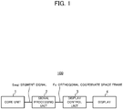
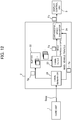
- FIG. 1 illustrates a block configuration of a LIDAR unit 100 according to the embodiment.
- the LIDAR unit 100 illustrated in FIG. 1 is a LIDAR (Light Detection and Ranging, or Laser Illuminated Detection and Ranging) based on TOF (Time of Flight), and performs a 360-degree ranging of objects in a horizontal direction to display the ranging result as an image.
- the LIDAR unit 100 is used for the purpose of an assistance of peripheral environment recognitions of a vehicle as a part of an advanced driving assistance system.
- the LIDAR unit 100 mainly includes a core unit 1, a signal processing unit 2, a display control unit 3 and a display 4.
- the core unit 1 emits pulse lasers at all directions equivalent to 360 degrees in the horizontal direction while gradually changing the outgoing direction of the pulse lasers.
- the core unit 1 emits a pulse laser per segment (out of 900 segments according to the embodiment) into which 360 degrees in the horizontal direction are evenly divided.
- the core unit 1 supplies the signal processing unit 2 with a signal (referred to as "segment signal Sseg") which indicates the received light intensity per segment measured by receiving a reflective light of the pulse laser in a predetermined duration after emitting the pulse laser.
- the signal processing unit 2 generates two dimensional image (referred to as "polar coordinate space frame Fp") in a polar coordinate space (polar coordinate system) by integrating the segment signals Sseg of all segments which are received from the core unit 1, wherein the polar coordinate space frame Fp indicates the relationship between each segment corresponding to each direction of 360 degrees in the horizontal direction and the corresponding distance from the LIDAR unit 100. Then, on the basis of the polar coordinate space frame Fp, the signal processing unit 2 generates a two dimensional image (referred to as "orthogonal coordinate space frame Fo") in the orthogonal (Cartesian) coordinate system based on the scan plate (irradiated plate) of pulse lasers and supplies the display control unit 3 therewith.
- the display control unit 3 displays on the display 4 an image based on the orthogonal coordinate space frame Fo received from the signal processing unit 2.
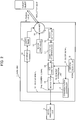
- FIG. 2 illustrates an example of a schematic configuration of the core unit 1.
- the core unit 1 mainly includes a crystal oscillator 10, a synchronization controller 11, a LD driver 12, a laser diode 13, a scanner 14, a motor controller 15, a photo detector 16, a current/voltage conversion circuit (Transimpedance Amplifier) 17, an A/D converter 18 and a segmenter 19.
- a crystal oscillator 10 mainly includes a crystal oscillator 10, a synchronization controller 11, a LD driver 12, a laser diode 13, a scanner 14, a motor controller 15, a photo detector 16, a current/voltage conversion circuit (Transimpedance Amplifier) 17, an A/D converter 18 and a segmenter 19.
- Transimpedance Amplifier Transimpedance Amplifier
- the crystal oscillator 10 supplies the synchronization controller 11 and the A/D converter 18 with a pulsed clock signal "S1".
- the clock frequency according to the embodiment is set to 1.8 GHz.
- each clock based on the clock signal S1 is also referred to as “sample clock”.
- the synchronization controller 11 supplies the LD driver 12 with a pulsed signal (referred to as "trigger signal S2").
- a time period from timing of asserting the trigger signal S2 to the next timing of asserting the trigger signal S2 is referred to as “segment period”.
- the synchronization controller 11 supplies the segmenter 19 with a signal (hereinafter referred to as "segment extraction signal S3") which determines the timing for the later-mentioned segmenter 19 to extract the output of the A/D converter 18.
- Each of the trigger signal S2 and the segment extraction signal S3 is a logic signal and they are synchronized with each other as illustrated in FIG. 3 to be mentioned later.
- the synchronization controller 11 asserts the segment extraction signal S3 for a time width (referred to as "gate width Wg") equivalent to 2048 sample clocks.
- the LD driver 12 supplies pulsed current to the laser diode 13 in synchronization with the trigger signal S2 inputted from the synchronization controller 11.
- the laser diode 13 is an infrared pulse laser with the wavelength of 905 nm and emits pulses of light based on the pulsed current supplied from the LD driver 12.
- the laser diode 13 according to the embodiment emits each pulse of light for approximately five nano seconds.
- the scanner 14 includes configurations of a transmission optical system and a receiving optical system. While scanning 360 degrees in the horizontal plane by use of pulses of light emitted from the laser diode 13, the scanner 14 leads, to the photo detector 16, the return light reflected at an object (referred to as "target object") that is irradiated with the pulses of emitted light.
- the scanner 14 includes a motor for revolving, and the motor is controlled by the motor controller 15 to revolve once every 900 segments.
- the LD driver 12 and the scanner 14 constitute an example of the "emitting unit" according to the present invention.
- the scan surface scanned by the scanner 14 is not an umbrella surface but a flat surface.
- the scan surface scanned by the scanner 14 is in parallel (i.e., horizontal) with the land surface on which the moving body travels. This leads to a high correlation between polar coordinate space frames Fp which are successively generated in time series as described later, and therefore it is possible to precisely display the peripheral environment.
- Examples of the photo detector 16 include an avalanche photodiode, and the photo detector 16 generates a slight current in accordance with the amount of the reflective light from the target object through the scanner 14.
- the photo detector 16 supplies the generated slight current to the current/voltage conversion circuit 17.
- the current/voltage conversion circuit 17 amplifies the slight current supplied from the photo detector 16 to thereby convert it to a voltage signal, and inputs the converted voltage signal to the A/D converter 18.
- the A/D converter 18 converts, on the basis of the clock signal S1 supplied from the crystal oscillator 10, the voltage signal supplied by the current/voltage conversion circuit 17 to the digital signal, and thereafter the A/D converter 18 supplies the converted digital signal to the segmenter 19.
- a digital signal which the A/D converter 18 generates per one clock is referred to as "sample”.
- One sample corresponds to one pixel data of the later-mentioned polar coordinate space frame Fp.
- the photo detector 16, the current/voltage conversion circuit 17 and the A/D converter 18 constitute an example of the "light receiving unit" according to the present invention.
- the segmenter 19 generates a segment signal Sseg by extracting digital signals which the A/D converter 18 outputs during the time period when the segment extraction signal S3 is asserted for the gate width Wg equivalent to 2048 sample clocks.
- the segmenter 19 supplies the generated segment signal Sseg to the signal processing unit 2.
- FIG. 3 illustrates a time-series waveforms corresponding to the trigger signal S2 and the segment extraction signal S3.
- a segment period that is one cycle of the trigger signal S2 being asserted is determined to have the length of 131072 sample clocks (referred to as "SMPCLK" in the drawings).
- the pulse width of the trigger signal S2 is determined to have the length of 64 sample clocks, and the gate width Wg is determined to have the length of 2048 sample clocks.
- the segmenter 19 extracts 2048 samples outputted by the A/D converter 18 during the trigger signal S2 being asserted.
- the frequency in the segment period is approximately 13.73 kHz (that is nearly equal to 1.8 GHz / 131072)
- the frame frequency (i.e., rotational velocity of the scanner 14) of the polar coordinate space frame Fp generated based on the segment signal Sseg by the signal processing unit 2 is approximately 15.36 Hz (that is nearly equal to 13.73kHz / 900) considering that one frame is configured of 900 segments.
- the maximum ranging distance is 170.55m (that is nearly equal to ⁇ 2048 / 1.8GHz ⁇ ⁇ c/2; "c" stands for light speed) corresponding to the distance where light shuttles for a time length corresponding to the gate width Wg.
- the maximum ranging distance is slightly shorter than 170.55m due to the later-described origin offset.
- FIG. 4 is a block diagram indicating the logical configuration of the signal processing unit 2.
- the signal processing unit 2 includes a frame generator 21, a buffer 22, a frame filter 23 and an orthogonal space converter 24.
- the frame generator 21 generates polar coordinate space frames Fp each of which is made from segment signals Sseg corresponding to 900 segments and stores the generated polar coordinate space frames Fp on the buffer 22. Given that there are 2048 samples per segment and that the number of all segments is 900 according to the embodiment, the frame generator 21 generates a 900 ⁇ 2048 image as a polar coordinate space frame Fp.
- the polar coordinate space frame Fp is an example of the "first information" and the "two dimensional signal in polar coordinate system” according to the present invention.
- the frame generator 21 and the above-mentioned segmenter 19 are examples of the "output unit” and the "generation unit” according to the present invention.
- the buffer 22 stores the polar coordinate space frame Fp generated by the frame generator 21 for at least a predetermined time.
- the length of the above-mentioned predetermined time is set to such a length that the necessary number of polar coordinate space frames Fp which the frame filter 23 needs are at least stored on the buffer 22.
- the frame filter 23 extracts a predetermined number (e.g., 16 frames) of time-series polar coordinate space frames Fp from the buffer 22 and applies a frame filtering to them to thereby generate the time-averaged polar coordinate space frame Fp (referred to as "averaged frame Fa"). Thereby, the frame filter 23 generates such an averaged frame Fa that the noise which appears in each polar coordinate space frame Fp is suppressed.
- the term "frame filtering" herein includes any processing to reduce the noise by use of time-series polar coordinate space frame Fp.
- the frame filter 23 may generate the averaged frame Fa by calculating the moving average of a predetermined number of the polar coordinate space frames Fp extracted from the buffer 22, or may generate the averaged frame Fa by applying a first order infinite impulse response filter thereto.
- the frame filter 23 is an example of the "first information processing unit" according to the present invention.
- the orthogonal space converter 24 generates an orthogonal coordinate space frame Fo by converting the coordinate system of the averaged frame Fa outputted by the frame filter 23 from a polar coordinate system into an orthogonal (Cartesian) coordinate system.
- the orthogonal space converter 24 generates the orthogonal coordinate space frame Fo by specifying each pixel of the averaged frame Fa to which the each pixel of the orthogonal coordinate space frame Fo corresponds. Concrete examples will be given later of the orthogonal coordinate space frame Fo and the generating method thereof. Then, the orthogonal space converter 24 supplies the generated orthogonal coordinate space frame Fo to the display control unit 3.
- the orthogonal space converter 24 is an example of the "conversion unit" according to the present invention.
- the orthogonal coordinate space frame Fo is an example of the "second information" and the "two dimensional signal in the orthogonal coordinate system" according to the present invention.
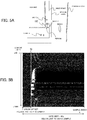
- FIG. 5A is a plane view schematically illustrating surroundings of the LIDAR unit 100.
- FIG. 5B illustrates a polar coordinate space frame Fp generated at the time when the LIDAR unit 100 is situated at the position indicated by FIG. 5A .
- target objects there are mainly a building, bicycles, a vehicle, first and second chain-link fences, a concrete wall, weeds and a person.
- the value of the sample index k indicated by the horizontal axis in FIG. 5B is in proportion to the distance (referred to as "target distance Ltag") to each target object.
- Td the delay time Td is a time length between the timing of asserting a trigger signal S2 and the timing of outputting a sample which corresponds to the pulse of light outputted based on the asserted trigger signal S2.
- the transmission route corresponds to a time period between the transmission of the trigger signal from the synchronization controller 11 to the LD driver 12 and the emission of light by the scanner 14, and wherein the receiving route corresponds to a time period between the incidence of the return light to the scanner 14 and the conversion to the digital signal by the A/D converter 18.
- the coordinate space of the polar coordinate space frame Fp is a polar coordinate space which has a vertical axis corresponding to the scan angle (i.e., angle) and a horizontal axis corresponding to the target distance Ltag (i.e., radius) .
- the frame generator 21 generates one polar coordinate space frame Fp by integrating them and stores the generated polar coordinate space frame Fp on the buffer 22.
- FIG. 6 illustrates the averaged frame Fa which the frame filter 23 generates based on time-series sixteen of polar coordinate space frames Fp.
- the frame filter 23 by applying a first-order IIR filter whose coefficient is one sixteenth, the frame filter 23 generates an averaged frame Fa to which the mean effect of approximately sixteen frames is added.
- the averaged frame Fa illustrated in FIG. 6 is compared to the polar coordinate space frame Fp illustrated in FIG. 5B , the high output areas corresponding to the noise that appears on the polar coordinate space frame Fp illustrated in FIG. 5B are smoothed.
- FIG. 7 is a display example of the orthogonal coordinate space frame Fo obtained on such an assumption that the polar coordinate space frame Fp illustrated in FIG. 5B is inputted to the orthogonal space converter 24.
- the orthogonal coordinate space frame Fo illustrated in FIG. 7 is a bitmap with 512 pixels of both horizontal and vertical sizes, and the central pixel position thereof corresponds to the position of the LIDAR unit 100.
- the length of a side of the orthogonal coordinate space frame Fo is equivalent to the maximum ranging distance (i.e., 170.55 m) that corresponds to the gate width Wg.
- FIG. 8 illustrates the orthogonal coordinate space frame Fo which the orthogonal space converter 24 generates from the averaged frame Fa illustrated in FIG. 6 .
- the LIDAR unit 100 can let the user explicitly recognize the existence and the position of each target object situated in the 360 degrees in the horizontal direction.
- the orthogonal space converter 24 calculates polar coordinate values each corresponding to each pixel of the orthogonal coordinate space frame Fo.
- the polar coordinate value is expressed by "(R, ⁇ )”
- the coordinate value corresponding to each pixel of the orthogonal coordinate space frame Fo is expressed by "(X, Y)”
- the values "R” and " ⁇ ” are expressed as the following equations based on a general formula of coordinate transformation.
- sample index k is expressed as the following equation (6) by substituting "R” for "Ltag” in the equation (2) and changing the equation with respect to the index k.
- k k0 + R ⁇ fsmp ⁇ 2 / c
- the orthogonal space converter 24 calculates the sample index k mostly corresponding to the orthogonal coordinate value (X, Y) of the orthogonal coordinate space frame Fo by referring to the equations (3) and (6) while calculating the segment index s mostly-corresponding to the orthogonal coordinate value (X, Y) of the orthogonal coordinate space frame Fo by referring to the equations (4) and (5). It is noted that, since the values "s" and "k” derived from the equations (3) to (6) are both real numbers, the orthogonal space converter 24 converts them to integer numbers by rounding. Thereby, each pixel of the averaged frame Fa or the polar coordinate space frame Fp which corresponds to each pixel of the orthogonal coordinate space frame Fo is specified.
- the display control unit 3 After the display control unit 3 receives the orthogonal coordinate space frame Fo from the orthogonal space converter 24, the display control unit 3 converts the pixel values of the orthogonal coordinate space frame Fo to luminance values by using a map of grayscale with a proper scale to thereby display an image. In this case, the display control unit 3 may display on the display 4 the orthogonal coordinate space frame Fo with colors which differ depending on the pixel value.
- a target object relatively moving with respect to the LIDAR unit 100 forms a line along the moving trajectory.
- the bicycles are moving (see FIG. 5A ) while the LIDAR unit 100 is still.
- the bicycles with trails are displayed. Even in this case, there is such an advantage that it can emphasize a moving object while suitably visualizing the moving direction of the moving object.
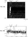
- FIG. 9C is an enlarged view of the peak of the waveform illustrated in FIG. 9B .
- a general LIDAR detects a target object and measures the distance thereto by calculating the target distance Ltag corresponding to the peak position of the output waveform per segment.
- the LIDAR additionally maximizes the signal-to-noise ratio by applying a matched filter before the detection of the peak position and/or specifies the real number of the sample index corresponding to the peak position through interpolation.
- the peak position is indicated by the mark 71.
- the first chain-link fence is situated at that position.
- the portion corresponding to the mark 72 forms a local peak in the waveform indicated by FIG. 10B .
- the second chain-link fence is situated at that position.
- the portion corresponding to the mark 73 does not form the peak in the waveform illustrated in FIG. 10B .
- the concrete wall is situated at that position.
- FIG. 11 plots, on the orthogonal coordinate system, point groups of the target objects detected by a typical LIDAR.
- FIG. 11 illustrates each position corresponding to the most noted peak per output waveform of each segment.
- the concrete wall behind the first and the second fences is not detected at all. Additionally, plotted circles are displayed even on the portion where any target object does not actually exist. This is because one peak is for sure detected per segment and plotted circles are displayed on the positions corresponding to the detected peaks.
- normal LIDAR products are normally equipped with such a function that only peaks higher than a predetermined threshold are selectively detected. However, setting such a predetermined threshold makes more difficult to detect a point group of a target object with a low reflection rate of the outgoing light. In this way, unfortunately, according to the specification of a conventional LIDAR which outputs information on a point group corresponding to the peak positions of waveforms received at each segment, information on target objects situated in the distance could be lost.
- the LIDAR unit 100 generates the polar coordinate space frame Fp from waveforms received at each segment without converting to point group information, and thereafter displays on the display 4 the orthogonal coordinate space frame Fo generated through coordinate conversion. It makes it possible to suitably visualize even a target object that cannot be detected when converting the waveforms to the point group information like conventional practices. Additionally, by displaying the orthogonal coordinate space frame Fo in which the polar coordinate space frame Fp is averaged along a temporal direction, the LIDAR unit 100 can enhance the visibility while suitably reducing the noise.
- the LIDAR unit 100 When the LIDAR unit 100 is mounted on a vehicle, target objects in the vicinity of the LIDAR unit 100 relatively moves with respect to the LIDAR unit 100 at the time of the vehicle traveling. In this case, since the orthogonal coordinate space frame Fo is generated based on the averaged frame Fa that is a time-averaged polar coordinate space frame Fp, lines along the moving trajectory appear on the orthogonal coordinate space frame Fo. To prevent the appearance, the LIDAR unit 100 may determine whether or not the vehicle on which the LIDAR unit 100 is mounted is at a stop to thereby execute the process by the frame filter 23 only at the time of determining that the vehicle is at a stop.
- FIG. 12 illustrates a schematic configuration of the signal processing unit 2 according to the first modification.
- the orthogonal space converter 24 generates the orthogonal coordinate space frame Fo based on the polar coordinate space frame Fp which the frame generator 21 generates.
- the orthogonal space converter 24 may generate the orthogonal coordinate space frame Fo by extracting from the buffer 22 the polar coordinate space frame Fp just after the frame generator 21 stores the polar coordinate space frame Fp on the buffer 22.
- the orthogonal space converter 24 generates the orthogonal coordinate space frame Fo based on the averaged frame Fa which the frame filter 23 outputs.
- the signal processing unit 2 may determine whether or not the vehicle is at a stop through the output of an acceleration sensor and/or a distance sensor which are not shown or may make the determination by receiving vehicle speed information based on a protocol such as CAN (Controller Area Network).
- CAN Controller Area Network
- the LIDAR unit 100 does not use the averaged frame Fa at the time of the vehicle traveling. Thereby, the LIDAR unit 100 can suppress target objects from being displayed on the orthogonal coordinate space frame Fo in such a state that the target objects have trails.
- the LIDAR unit 100 may determine the number (i.e., the depth of the filter) of the polar coordinate space frames Fp used for generating the orthogonal coordinate space frame Fo. Namely, the LIDAR unit 100 may determine the time duration for averaging the polar coordinate space frame Fp. In this case, the LIDAR unit 100 may acquire the vehicle speed information from unshown sensor(s) and/or the vehicle.
- the higher the relative speed between the LIDAR unit 100 and a target object is, the longer the moving distance of the target object between time-series polar coordinate space frames Fp becomes and therefore the longer the lines of the moving trajectories which appear on the orthogonal coordinate space frame Fo tend to be.
- the above-mentioned map is a map between the vehicle speed and parameter(s) for determining the number of the polar coordinate space frames Fp used for generating the orthogonal coordinate space frame Fo.
- the map is prepared in advance through experimental trials . Thereby, it is possible to suitably suppress the deterioration of the visibility due to the excessively-long lines of the moving trajectories which appear on the orthogonal coordinate space frame Fo.
- the frame generator 21 may suppress the noise by applying a matched filter to the waveform indicated by the segment signal Sseg received from the core unit 1. Then, in this case, the orthogonal space converter 24 generates the orthogonal coordinate space frame Fo by converting, to the orthogonal coordinate system, the polar coordinate space frame Fp whose noise is suppressed through the matched filter or the averaged frame Fa that is a time-averaged polar coordinate space frame Fp. According to this mode, the LIDAR unit 100 can display an image on which the noise is suitably reduced on the display 4.
- the configuration of the LIDAR unit 100 is not limited to the configuration illustrated in FIG. 1 .
- the LIDAR unit 100 may not be equipped with the display control unit 3 and the display 4.
- the LIDAR unit 100 detects a target object through a known image recognition processing over the orthogonal coordinate space frame Fo which the signal processing unit 2 generates and informs the existence of the target object through an audio output device.
- the LIDAR unit 100 may store the orthogonal coordinate space frame Fo which the signal processing unit 2 generates on its storage unit as with the present position information of the LIDAR unit 100 outputted by a GPS receiver or the like.
- the LIDAR unit 100 may generate the orthogonal coordinate space frame Fo per layer by repeating horizontal scanning by the scanner 14 on multiple layers which are lined in the vertical direction.
- the configuration of the core unit 1 illustrated in FIG. 2 is an example and the configuration of the core unit 1 to which the present invention can be applied is not limited to the configuration illustrated in FIG. 2 .
- the laser diode 13 and the motor controller 15 may be configured to rotate together with the scanner 14.
Landscapes
- Engineering & Computer Science (AREA)
- Physics & Mathematics (AREA)
- Radar, Positioning & Navigation (AREA)
- Remote Sensing (AREA)
- Computer Networks & Wireless Communication (AREA)
- General Physics & Mathematics (AREA)
- Electromagnetism (AREA)
- Optical Radar Systems And Details Thereof (AREA)
Applications Claiming Priority (1)
| Application Number | Priority Date | Filing Date | Title |
|---|---|---|---|
| PCT/JP2015/074685 WO2017037834A1 (fr) | 2015-08-31 | 2015-08-31 | Dispositif de traitement d'informations, procédé de commande, programme et support de stockage |
Publications (2)
| Publication Number | Publication Date |
|---|---|
| EP3346285A1 true EP3346285A1 (fr) | 2018-07-11 |
| EP3346285A4 EP3346285A4 (fr) | 2019-05-01 |
Family
ID=58186747
Family Applications (1)
| Application Number | Title | Priority Date | Filing Date |
|---|---|---|---|
| EP15902956.0A Withdrawn EP3346285A4 (fr) | 2015-08-31 | 2015-08-31 | Dispositif de traitement d'informations, procédé de commande, programme et support de stockage |
Country Status (5)
| Country | Link |
|---|---|
| US (1) | US20180246192A1 (fr) |
| EP (1) | EP3346285A4 (fr) |
| JP (1) | JPWO2017037834A1 (fr) |
| CN (1) | CN107923968A (fr) |
| WO (1) | WO2017037834A1 (fr) |
Families Citing this family (2)
| Publication number | Priority date | Publication date | Assignee | Title |
|---|---|---|---|---|
| JP2019117053A (ja) * | 2017-12-26 | 2019-07-18 | パイオニア株式会社 | 表示制御装置 |
| CN112735163B (zh) * | 2020-12-25 | 2022-08-02 | 阿波罗智联(北京)科技有限公司 | 确定目标物体静止状态的方法、路侧设备、云控平台 |
Family Cites Families (24)
| Publication number | Priority date | Publication date | Assignee | Title |
|---|---|---|---|---|
| JP2584530Y2 (ja) * | 1993-03-29 | 1998-11-05 | 日本電気ホームエレクトロニクス株式会社 | 対物距離計測装置 |
| JP3849324B2 (ja) * | 1998-11-02 | 2006-11-22 | 株式会社デンソー | 距離測定装置 |
| JP3685970B2 (ja) * | 1999-12-27 | 2005-08-24 | 本田技研工業株式会社 | 物体検知装置 |
| JP2005233716A (ja) * | 2004-02-18 | 2005-09-02 | Omron Corp | レーダ装置 |
| JP2007232381A (ja) * | 2006-02-27 | 2007-09-13 | Omron Corp | レーダ装置 |
| JP2007248146A (ja) * | 2006-03-14 | 2007-09-27 | Omron Corp | レーダ装置 |
| DE602006014263D1 (de) * | 2006-07-03 | 2010-06-24 | Trimble Ab | Vermessungsinstrument und Verfahren zur Steuerung eines Vermessungsinstruments |
| JP5092076B2 (ja) * | 2007-10-26 | 2012-12-05 | オプテックス株式会社 | レーザエリアセンサ |
| JP5142826B2 (ja) * | 2008-05-29 | 2013-02-13 | Ihi運搬機械株式会社 | 物体の位置情報算出方法 |
| US9250315B2 (en) * | 2009-03-04 | 2016-02-02 | Toyota Motor Engineering & Manufacturing North America, Inc. | Collision avoidance system and method |
| JP5267588B2 (ja) * | 2010-03-26 | 2013-08-21 | 株式会社デンソー | 区画線検出装置および区画線検出方法 |
| JP5804467B2 (ja) * | 2010-03-31 | 2015-11-04 | 北陽電機株式会社 | 信号処理装置、及び走査式測距装置 |
| JP5620200B2 (ja) * | 2010-09-06 | 2014-11-05 | 株式会社トプコン | 点群位置データ処理装置、点群位置データ処理方法、点群位置データ処理システム、および点群位置データ処理プログラム |
| JP5701106B2 (ja) * | 2011-03-04 | 2015-04-15 | 富士通テン株式会社 | レーダ装置及び該レーダ装置の到来角算出方法 |
| JP5402968B2 (ja) * | 2011-03-21 | 2014-01-29 | 株式会社デンソー | 車両用道路形状認識方法及び装置、記録媒体 |
| AT511310B1 (de) * | 2011-04-07 | 2013-05-15 | Riegl Laser Measurement Sys | Verfahren zur entfernungsmessung |
| JP5679907B2 (ja) * | 2011-06-02 | 2015-03-04 | 三菱電機株式会社 | レーザレーダ装置 |
| US8994925B2 (en) * | 2012-03-27 | 2015-03-31 | Pulsedlight, Inc. | Optical distance measurement device |
| US9097800B1 (en) * | 2012-10-11 | 2015-08-04 | Google Inc. | Solid object detection system using laser and radar sensor fusion |
| JP2014106854A (ja) * | 2012-11-29 | 2014-06-09 | Toyota Infotechnology Center Co Ltd | 自動運転車両制御装置および方法 |
| US9277204B2 (en) * | 2013-01-23 | 2016-03-01 | Advanced Scientific Concepts, Inc. | Modular LADAR sensor |
| KR102136401B1 (ko) * | 2013-10-21 | 2020-07-21 | 한국전자통신연구원 | 다-파장 이미지 라이다 센서장치 및 이의 신호처리 방법 |
| CN103760569B (zh) * | 2013-12-31 | 2016-03-30 | 西安交通大学 | 一种基于激光雷达的可行驶区域检测方法 |
| CN104569998B (zh) * | 2015-01-27 | 2017-06-20 | 长春理工大学 | 基于激光雷达的车辆安全行驶区域的检测方法及装置 |
-
2015
- 2015-08-31 EP EP15902956.0A patent/EP3346285A4/fr not_active Withdrawn
- 2015-08-31 WO PCT/JP2015/074685 patent/WO2017037834A1/fr active Application Filing
- 2015-08-31 US US15/756,482 patent/US20180246192A1/en not_active Abandoned
- 2015-08-31 JP JP2017537098A patent/JPWO2017037834A1/ja active Pending
- 2015-08-31 CN CN201580082730.3A patent/CN107923968A/zh active Pending
Also Published As
| Publication number | Publication date |
|---|---|
| JPWO2017037834A1 (ja) | 2018-07-26 |
| CN107923968A (zh) | 2018-04-17 |
| WO2017037834A1 (fr) | 2017-03-09 |
| US20180246192A1 (en) | 2018-08-30 |
| EP3346285A4 (fr) | 2019-05-01 |
Similar Documents
| Publication | Publication Date | Title |
|---|---|---|
| US10965099B2 (en) | Light control device, control method, program and storage medium | |
| EP2975428B1 (fr) | Système radar d'imagerie tridimensionnelle | |
| US20190049582A1 (en) | Information processing device, control method, program and storage medium | |
| US7952690B2 (en) | Method and system for acquiring a 3-D image of a scene | |
| EP2815251B1 (fr) | Caméra de temps de vol avec éclairage en bande | |
| US9513367B2 (en) | Image gated camera for detecting objects in a marine environment | |
| CN111868561A (zh) | 使用本底噪声的自适应识别进行有效信号检测 | |
| CN107533127A (zh) | 改善的激光扫描的装置和方法 | |
| JP6855746B2 (ja) | 測距装置、監視カメラ、3次元計測装置、移動体、ロボット及び測距方法 | |
| EP3563177B1 (fr) | Système de caractérisation de l'environnement d'un véhicule | |
| JP2006209318A (ja) | 人数検出装置及び方法 | |
| KR20160090464A (ko) | 티오에프 카메라에서 깊이 지도 생성 방법 | |
| US20240125936A1 (en) | Time-resolved contrast imaging for lidar | |
| EP2275833A1 (fr) | Caméra mesurant la distance et procédé d'acquisition d'image de distance | |
| EP3346285A1 (fr) | Dispositif de traitement d'informations, procédé de commande, programme et support de stockage | |
| US20210116676A1 (en) | System and method | |
| US20210003676A1 (en) | System and method | |
| EP2910974A1 (fr) | Procédé de surveillance laser et dispositif de surveillance laser | |
| JP2023093724A (ja) | 情報処理装置、制御方法、プログラム及び記憶媒体 | |
| WO2022195954A1 (fr) | Système de détection | |
| EP2749899A2 (fr) | Procédé de différenciation entre un objet cible et un composant atmosphérique dans une mesure à l'aide d'un dispositif de capteur optoélectronique d'un véhicule automobile, véhicule automobile et dispositif de capteur | |
| CN108120990A (zh) | 一种提高距离选通夜视仪测距精度的方法 | |
| RU2811331C1 (ru) | Устройство формирования изображения карты дальностей до наблюдаемых объектов | |
| RU2593627C1 (ru) | Активно-импульсный комплекс ночного видения | |
| RU2549210C2 (ru) | Способ обнаружения объекта на малых дистанциях и устройство для его осуществления |
Legal Events
| Date | Code | Title | Description |
|---|---|---|---|
| STAA | Information on the status of an ep patent application or granted ep patent |
Free format text: STATUS: THE INTERNATIONAL PUBLICATION HAS BEEN MADE |
|
| PUAI | Public reference made under article 153(3) epc to a published international application that has entered the european phase |
Free format text: ORIGINAL CODE: 0009012 |
|
| STAA | Information on the status of an ep patent application or granted ep patent |
Free format text: STATUS: REQUEST FOR EXAMINATION WAS MADE |
|
| 17P | Request for examination filed |
Effective date: 20180215 |
|
| AK | Designated contracting states |
Kind code of ref document: A1 Designated state(s): AL AT BE BG CH CY CZ DE DK EE ES FI FR GB GR HR HU IE IS IT LI LT LU LV MC MK MT NL NO PL PT RO RS SE SI SK SM TR |
|
| AX | Request for extension of the european patent |
Extension state: BA ME |
|
| RIN1 | Information on inventor provided before grant (corrected) |
Inventor name: ABE, YOSHINORI Inventor name: KITANO, KAZUTOSHI |
|
| DAV | Request for validation of the european patent (deleted) | ||
| DAX | Request for extension of the european patent (deleted) | ||
| A4 | Supplementary search report drawn up and despatched |
Effective date: 20190328 |
|
| RIC1 | Information provided on ipc code assigned before grant |
Ipc: G01S 17/89 20060101ALI20190322BHEP Ipc: G01S 7/487 20060101AFI20190322BHEP |
|
| STAA | Information on the status of an ep patent application or granted ep patent |
Free format text: STATUS: EXAMINATION IS IN PROGRESS |
|
| STAA | Information on the status of an ep patent application or granted ep patent |
Free format text: STATUS: EXAMINATION IS IN PROGRESS |
|
| 17Q | First examination report despatched |
Effective date: 20211006 |
|
| STAA | Information on the status of an ep patent application or granted ep patent |
Free format text: STATUS: THE APPLICATION IS DEEMED TO BE WITHDRAWN |
|
| 18D | Application deemed to be withdrawn |
Effective date: 20220217 |