EP3345507A1 - Mechanism for a chair - Google Patents
Mechanism for a chair Download PDFInfo
- Publication number
- EP3345507A1 EP3345507A1 EP18000037.4A EP18000037A EP3345507A1 EP 3345507 A1 EP3345507 A1 EP 3345507A1 EP 18000037 A EP18000037 A EP 18000037A EP 3345507 A1 EP3345507 A1 EP 3345507A1
- Authority
- EP
- European Patent Office
- Prior art keywords
- seat
- seat support
- backrest
- support member
- chair
- Prior art date
- Legal status (The legal status is an assumption and is not a legal conclusion. Google has not performed a legal analysis and makes no representation as to the accuracy of the status listed.)
- Granted
Links
- 230000007246 mechanism Effects 0.000 title claims abstract description 66
- 230000033001 locomotion Effects 0.000 claims description 71
- 230000008878 coupling Effects 0.000 description 15
- 238000010168 coupling process Methods 0.000 description 15
- 238000005859 coupling reaction Methods 0.000 description 15
- 230000001360 synchronised effect Effects 0.000 description 6
- 230000000712 assembly Effects 0.000 description 4
- 238000000429 assembly Methods 0.000 description 4
- 230000000694 effects Effects 0.000 description 3
- 238000005096 rolling process Methods 0.000 description 3
- 230000008901 benefit Effects 0.000 description 2
- 238000010276 construction Methods 0.000 description 2
- 239000013013 elastic material Substances 0.000 description 2
- 238000004519 manufacturing process Methods 0.000 description 2
- 239000000463 material Substances 0.000 description 2
- 239000000243 solution Substances 0.000 description 2
- 230000005540 biological transmission Effects 0.000 description 1
- 230000015572 biosynthetic process Effects 0.000 description 1
- 238000000605 extraction Methods 0.000 description 1
- 230000005283 ground state Effects 0.000 description 1
- 239000004615 ingredient Substances 0.000 description 1
- 230000000977 initiatory effect Effects 0.000 description 1
- 238000001746 injection moulding Methods 0.000 description 1
- 229920003023 plastic Polymers 0.000 description 1
- 239000004033 plastic Substances 0.000 description 1
- 238000000926 separation method Methods 0.000 description 1
- 230000007704 transition Effects 0.000 description 1
Images


Classifications
-
- A—HUMAN NECESSITIES
- A47—FURNITURE; DOMESTIC ARTICLES OR APPLIANCES; COFFEE MILLS; SPICE MILLS; SUCTION CLEANERS IN GENERAL
- A47C—CHAIRS; SOFAS; BEDS
- A47C1/00—Chairs adapted for special purposes
- A47C1/02—Reclining or easy chairs
- A47C1/031—Reclining or easy chairs having coupled concurrently adjustable supporting parts
- A47C1/034—Reclining or easy chairs having coupled concurrently adjustable supporting parts the parts including a leg-rest or foot-rest
- A47C1/035—Reclining or easy chairs having coupled concurrently adjustable supporting parts the parts including a leg-rest or foot-rest in combination with movably coupled seat and back-rest, i.e. the seat and back-rest being movably coupled in such a way that the extension mechanism of the foot-rest is actuated at least by the relative movements of seat and backrest
-
- A—HUMAN NECESSITIES
- A47—FURNITURE; DOMESTIC ARTICLES OR APPLIANCES; COFFEE MILLS; SPICE MILLS; SUCTION CLEANERS IN GENERAL
- A47C—CHAIRS; SOFAS; BEDS
- A47C1/00—Chairs adapted for special purposes
- A47C1/02—Reclining or easy chairs
- A47C1/022—Reclining or easy chairs having independently-adjustable supporting parts
-
- A—HUMAN NECESSITIES
- A47—FURNITURE; DOMESTIC ARTICLES OR APPLIANCES; COFFEE MILLS; SPICE MILLS; SUCTION CLEANERS IN GENERAL
- A47C—CHAIRS; SOFAS; BEDS
- A47C1/00—Chairs adapted for special purposes
- A47C1/02—Reclining or easy chairs
- A47C1/031—Reclining or easy chairs having coupled concurrently adjustable supporting parts
- A47C1/032—Reclining or easy chairs having coupled concurrently adjustable supporting parts the parts being movably-coupled seat and back-rest
- A47C1/03255—Reclining or easy chairs having coupled concurrently adjustable supporting parts the parts being movably-coupled seat and back-rest with a central column, e.g. rocking office chairs
-
- A—HUMAN NECESSITIES
- A47—FURNITURE; DOMESTIC ARTICLES OR APPLIANCES; COFFEE MILLS; SPICE MILLS; SUCTION CLEANERS IN GENERAL
- A47C—CHAIRS; SOFAS; BEDS
- A47C3/00—Chairs characterised by structural features; Chairs or stools with rotatable or vertically-adjustable seats
- A47C3/12—Chairs characterised by structural features; Chairs or stools with rotatable or vertically-adjustable seats with shell-shape seat and back-rest unit, e.g. having arm rests
Landscapes
- Health & Medical Sciences (AREA)
- Dentistry (AREA)
- General Health & Medical Sciences (AREA)
- Chairs Characterized By Structure (AREA)
- Chairs For Special Purposes, Such As Reclining Chairs (AREA)
Abstract
Die Erfindung betrifft eine Mechanik (1) für einen Stuhl, insbesondere für einen Bürostuhl. Um den Sitzkomfort einer Stuhlmechanik zu verbessern, wird eine Mechanik (1) für einen Stuhl vorgeschlagen, mit einem auf einer Stuhlsäule plazierbaren Basisträger (2), mit einem auf dem Basisträger (2) angeordneten, relativ zu dem Basisträger (2) in Stuhllängsrichtung (8) bewegbaren Sitzträger (4), und mit einem mit dem Sitzträger (4) verbundenen Rückenlehnenträger (5), dadurch gekennzeichnet, daß der Sitzträger (4) ein erstes Sitzträgerelement (6) und ein zweites Sitzträgerelement (7) umfaßt, wobei das zweite Sitzträgerelement (7) relativ zu dem ersten Sitzträgerelement (6) quer zur Stuhllängsrichtung (8) bewegbar ist und/oder daß der Rückenlehnenträger (5) ein erstes Rückenlehnenträgerelement (9) und ein zweites Rückenlehnenträgerelement (11) umfaßt, wobei das zweite Rückenlehnenträgerelement (11) relativ zu dem ersten Rückenlehnenträgerelement (9) um eine in Stuhllängsrichtung (8) liegende Drehachse (12) drehbar ist.

Description
Die Erfindung betrifft eine Mechanik für einen Stuhl, insbesondere für einen Bürostuhl. Darüber hinaus betrifft die Erfindung einen Stuhl mit einer solchen Stuhlmechanik.The invention relates to a mechanism for a chair, in particular for an office chair. Moreover, the invention relates to a chair with such a chair mechanism.
Als Mechaniken für Bürostühle sind u. a. Synchronmechaniken, Asynchronmechaniken und Wippmechaniken bekannt.As mechanisms for office chairs u. a. Synchronous mechanisms, asynchronous mechanisms and rocking mechanisms known.
Unter der Bezeichnung Synchronmechanik werden dabei Baugruppen im Sitzunterbau eines Bürostuhles verstanden, die für eine miteinander gekoppelte, eine bestimmte Relativbewegung von Sitz-und Rückenlehne zueinander mit sich bringende Kinematik sorgen. Auf dem Sitzträger ist der in aller Regel mit einer gepolsterten Sitzfläche versehene Sitz des Bürostuhles montiert. Der Rückenlehnenträger, der sich in gängiger Weise von der eigentlichen Synchronmechanik nach hinten erstreckt, trägt an einem nach oben verlaufenden Ausleger die Rückenlehne des Bürostuhles. Sitzträger und Rückenlehnenträger sind üblicherweise derart gelenkig gekoppelt, daß eine Schwenkbewegung der Rückenlehne nach hinten - wie sie beispielsweise durch ein Anlehnen des Stuhlbenutzers an die Rückenlehne hervorgerufen werden kann - eine Absenkbewegung der Hinterkante des Sitzes nach unten induziert. Dadurch wird der sogenannte "Hemdauszieheffekt" verhindert und der Sitzkomfort erhöht.The term synchronizing mechanism is understood to mean assemblies in the seat substructure of an office chair, which provide kinematics which are coupled to one another and bring about a certain relative movement of the seat and backrest. On the seat support of the usually provided with a padded seat seat of the office chair is mounted. The backrest support, which extends in a conventional manner from the actual synchronizing mechanism to the rear, carries on an upwardly extending arm, the backrest of the office chair. Seat support and backrest support are usually coupled so articulated that a pivoting movement of the backrest to the rear - as can be caused for example by leaning of the chair user to the backrest - induces a lowering movement of the rear edge of the seat down. As a result, the so-called "shirt pull-out effect" is prevented and the seating comfort is increased.
Unter der Bezeichnung Asynchronmechanik werden solche Baugruppen verstanden, bei denen eine Verschwenkung der Rückenlehne keine Bewegung des Sitzträgers hervorruft. Mit anderen Worten bewegt sich bei einem Verschwenken nach hinten ausschließlich die Rückenlehne. Der Sitzkomfort ist im Vergleich zu Synchronmechaniken vermindert. Insbesondere kann bei Asynchronmechaniken aufgrund eines "Auseinanderlaufens" der Bewegungen von Rückenlehne und Sitz der sogenannte "Hemdauszieheffekt" auftreten. Allerdings sind solche Baugruppen wegen ihres vergleichsweise einfachen Aufbaus deutlich preiswerter in der Herstellung als die zuvor beschriebenen Synchronmechaniken.The term asynchronous mechanism is understood to mean those assemblies in which a pivoting of the backrest causes no movement of the seat support. In other words, moving only when turning backwards Backrest. The seating comfort is reduced compared to synchronous mechanisms. In particular, in asynchronous mechanisms due to a "divergence" of the movements of the backrest and seat of the so-called "shirt extraction effect" occur. However, because of their comparatively simple construction, such assemblies are significantly cheaper to manufacture than the synchronizing mechanisms described above.
Bei Wippmechaniken handelt es sich um vergleichsweise einfach aufgebaute Baugruppen im Sitzunterbau von Stühlen, bei denen der Rückenlehnenträger mehr oder weniger starr mit dem Sitzträger, dem Sitz oder dem Rahmen des Stuhles verbunden ist. Die so entstehende Sitzträger-Rückenlehnenträger-Kombination ist mittels der Wippmechanik um eine quer zu der Stuhllängsrichtung verlaufende Schwenkachse nach hinten verschwenkbar, wenn sich der Benutzer des Stuhls an die Rückenlehne anlehnt. Derartige Wippmechaniken werden oftmals anstelle von Synchronmechaniken in preiswerten Besucher- oder Konferenzstühlen verwendet, um dort eine einfache Wippfunktion zu realisieren. Wegen ihres vergleichsweise einfachen Aufbaus sind Wippmechaniken meist deutlich preiswerter in der Herstellung als die zuvor beschriebenen Mechaniken.Rocking mechanisms are comparatively simple assemblies in the seat base of chairs, in which the backrest support is more or less rigidly connected to the seat support, the seat or the frame of the chair. The resulting seat carrier backrest support combination is pivotable by means of the tilt mechanism to a transverse to the chair longitudinal direction pivot axis to the rear when the user of the chair leans against the backrest. Such rocking mechanisms are often used instead of synchronous mechanisms in inexpensive visitor or conference chairs to realize there a simple Wippfunktion. Because of their relatively simple structure, rocking mechanisms are usually significantly cheaper to manufacture than the previously described mechanisms.
All diesen Mechaniken ist es gemeinsam, daß eine Schwenkbewegung einzelner oder mehrerer Mechanikkomponenten in Stuhllängsrichtung, d.h. nach vorn oder hinten, möglich ist.All these mechanisms have in common that a pivoting movement of one or more mechanical components in the chair longitudinal direction, i. forward or backward, is possible.
Eine Aufgabe der vorliegenden Erfindung ist es, den Sitzkomfort von Stuhlmechaniken zu verbessern.An object of the present invention is to improve the seating comfort of chair mechanisms.
Diese Aufgabe wird durch eine Mechanik nach Anspruch 1 bzw. durch einen Stuhl nach Anspruch 15 gelöst. Vorteilhafte Ausführungen der Erfindung sind in den Unteransprüchen angegeben.This object is achieved by a mechanism according to
Die im Folgenden im Zusammenhang mit der Stuhlmechanik erläuterten Vorteile und Ausgestaltungen gelten sinngemäß auch für den erfindungsgemäßen Stuhl und umgekehrt.The advantages and embodiments explained below in connection with the chair mechanism also apply mutatis mutandis to the chair according to the invention and vice versa.
Die erfindungsgemäße Stuhlmechanik umfaßt einen auf einer Stuhlsäule plazierbaren Basisträger, einen auf dem Basisträger angeordneten Sitzträger sowie einen mit dem Sitzträger verbundenen Rückenlehnenträger und ist dadurch gekennzeichnet,
- daß der Sitzträger ein erstes Sitzträgerelement und ein zweites Sitzträgerelement umfaßt, wobei das zweite Sitzträgerelement relativ zu dem ersten Sitzträgerelement quer zur Stuhllängsrichtung bewegbar ist
- daß der Rückenlehnenträger ein erstes Rückenlehnenträgerelement und ein zweites Rückenlehnenträgerelement umfaßt, wobei das zweite Rückenlehnenträgerelement relativ zu dem ersten Rückenlehnenträgerelement um eine in Stuhllängsrichtung liegende Drehachse drehbar ist.
- in that the seat support comprises a first seat support element and a second seat support element, wherein the second seat support element is movable relative to the first seat support element transversely to the chair longitudinal direction
- in that the backrest support comprises a first backrest support element and a second backrest support element, wherein the second backrest support element is rotatable relative to the first backrest support element about an axis of rotation lying in the chair longitudinal direction.
Mit der Erfindung wird eine Stuhlmechanik mit einem verbesserten Sitzkomfort geschaffen.The invention provides a chair mechanism with improved seating comfort.
Eine Kernidee der Erfindung ist es, alternativ oder zusätzlich zu der oben beschriebenen Schwenkbewegung nach vorn und hinten eine Neigebewegung einzelner oder mehrerer Mechanikkomponenten nach rechts und links zu ermöglichen.A core idea of the invention is to allow, as an alternative or in addition to the above-described pivoting movement forwards and backwards, a tilting movement of one or more mechanical components to the right and left.
In Ausführungsformen der Erfindung ist hierfür ein zweigeteilter Sitzträger vorgesehen. In anderen Ausführungsformen der Erfindung ist zusätzlich ein zweigeteilter Rückenlehnenträger vorgesehen und die gewünschte Querbewegung des Sitzträgers wird über geeignete Mittel auf den Rückenlehnenträger übertragen oder umgekehrt.In embodiments of the invention, a two-part seat support is provided for this purpose. In other embodiments of the invention, a two-part backrest support is additionally provided and the desired transverse movement of the seat support is transmitted to the backrest support via suitable means or vice versa.
Vorteilhafterweise sind die Bewegungen der einzelnen Mechanikkomponenten voneinander unabhängig ausführbar. Das bedeutet beispielsweise, daß eine Neigebewegung einer Sitzträgerkomponente in Stuhllängsrichtung gesehen nach rechts oder links unabhängig von einer Schwenkbewegung des Sitzträgers nach vorn oder hinten möglich ist. Dies wird dadurch erreicht, daß gegenüber einer herkömmlichen Stuhlmechanik die Anzahl der zur Verfügung stehenden Freiheitsgrade erhöht wird. Es ergibt sich gegenüber herkömmlichen Lösungen ein verbessertes Bewegungsverhalten des Stuhls auf Bewegungen des Benutzers.Advantageously, the movements of the individual mechanical components are independently executable. This means, for example, that a tilting movement of a seat support component seen in the chair longitudinal direction to the right or left regardless of a pivoting movement of the seat support forward or backward is possible. This is achieved in that over a conventional chair mechanism, the number of available degrees of freedom is increased. It results over conventional solutions improved movement behavior of the chair to movements of the user.
Ausführungsbeispiele der Erfindung werden nachfolgend anhand der Zeichnungen näher erläutert. Hierbei zeigen:
- Fig. 1-15
- Darstellungen eines ersten Ausführungsbeispiels,
- Fig. 16
- eine Darstellung eines zweiten Ausführungsbeispiels,
- Fig. 17
- eine Darstellung eines dritten Ausführungsbeispiels,
- Fig. 18
- eine Darstellung eines vierten Ausführungsbeispiels.
- Fig. 1-15
- Representations of a first embodiment,
- Fig. 16
- a representation of a second embodiment,
- Fig. 17
- a representation of a third embodiment,
- Fig. 18
- an illustration of a fourth embodiment.
Sämtliche Figuren zeigen die Erfindung nicht maßstabsgerecht, dabei lediglich schematisch und nur mit ihren wesentlichen Bestandteilen. Gleiche Bezugszeichen entsprechen dabei Elementen gleicher oder vergleichbarer Funktion.All figures show the invention not to scale, only schematically and only with their essential Ingredients. The same reference numerals correspond to elements of the same or comparable function.
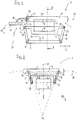
Die Mechanik 1 weist einen Basisträger 2 auf, der mittels einer Konusaufnahme 3 auf das obere Ende einer Stuhlsäule (nicht abgebildet) gesetzt ist. Die Mechanik 1 umfaßt einen Sitzträger 4, der auf dem Basisträger 2 angeordnet und relativ zu dem feststehenden Basisträger 2 in Stuhllängsrichtung 8 nach vorn und hinten bewegbar ist. Auf dem Sitzträger 4 ist der in aller Regel mit einer gepolsterten Sitzfläche versehen Sitz (nicht abgebildet) des Bürostuhls montiert.The
Der Sitzträger 4 umfaßt ein erstes Sitzträgerelement 6 und ein zweites Sitzträgerelement 7, wobei das zweite Sitzträgerelement 7 relativ zu dem ersten Sitzträgerelement 6 quer zur Stuhllängsrichtung 8, d.h. nach rechts und links, bewegbar ist. Bei dem ersten Sitzträgerelement 6 handelt es sich um die getrennt von dem eigentlichen Sitz angebrachte Sitzträgerbasis, ein Element des Sitzträgers 4, das mit dem Basisträger 2 zusammenwirkt. Bei dem zweiten Sitzträgerelement 7 handelt es sich um das Sitzmontageelement, welches entweder den Sitz mit Sitzfläche umfaßt oder aber - beispielsweise ausgeführt als Montageplatte - die für eine Sitzmontage notwendigen Voraussetzungen bietet.The seat support 4 comprises a first
Die Mechanik 1 umfaßt außerdem einen Rückenlehnenträger 5, der mit dem Sitzträger 4 und dem Basisträger 2 verbunden ist. Mit dem Rückenlehnenträger 5 verbunden ist die in aller Regel mit einer gepolsterten Anlehnfläche versehene Rückenlehne (nicht abgebildet) des Bürostuhls.The
Der Rückenlehnenträger 5 umfaßt ein erstes Rückenlehnenträgerelement 9 und ein zweites Rückenlehnenträgerelement 11, wobei das zweite Rückenlehnenträgerelement 11 relativ zu dem ersten Rückenlehnenträgerelement 8 um eine in Stuhllängsrichtung 8 liegende Drehachse 12 (Neigeachse) drehbar (neigbar) ist. Bei dem ersten Rückenlehnenträgerelement 9 handelt es sich um die Rückenlehnenträgerbasis, ein Element des Rückenlehnenträgers 5, das mit dem Basisträger zusammenwirkt. Bei dem zweiten Rückenlehnenträgerelement 11 handelt es sich um das Rückenlehnenmontageelement, welches entweder die Rückenlehne mit Anlehnfläche umfaßt oder aber - beispielsweise ausgeführt als Montageadapter - die für eine Rückenlehnenmontage notwendigen Voraussetzungen bietet.The
Der Rückenlehnenträger 5 ist sowohl mit dem in Stuhllängsrichtung 8 gesehen hinteren Ende 13 des ersten Sitzträgerelements 6 als auch mit dem hinteren Ende 14 des Basisträgers 2 um quer zur Stuhllängsrichtung 8 verlaufende hintere Drehachsen 15, 16 schwenkbar verbunden, wobei der Verbindungsbereich des Rückenlehnenträgers 5 zwischen diesen beiden Drehachsen 15, 16 als hinteres Koppelelement 17 zwischen Basisträger 2 und Sitzträger 4 dient. Ein vorderes Koppelelement 18 ist sowohl mit dem in Stuhllängsrichtung 8 gesehen vorderen Ende 21 des Basisträgers 2 als auch mit dem vorderen Ende 19 des ersten Sitzträgerelements 6 um quer zur Sitzlängsrichtung 8 verlaufende vordere Drehachsen 22, 23 schwenkbar verbunden.The
Aufgrund der beschriebenen Verbindung des Rückenlehnenträgers 5 mit dem Sitzträger 4 hat ein Verschwenken des Rückenlehnenträgers 5 in Schwenkrichtung 24 nach hinten, d.h. von einer aufrechten Ausgangsposition (
Die Art und Weise der Ankopplung des verschwenkbaren Rückenlehnenträgers 5 an das erste Sitzträgerelement 6 und/oder den Basisträger 2 spielt für die vorliegende Erfindung keine Rolle. Es kann sich dabei um eine direkte oder eine indirekte Ankopplung handeln. Gleiches gilt für die Anlenkung des Rückenlehnenträgers 5 an den Basisträger 2 und den Sitzträger 4 und damit die konkrete Ausgestaltung der Synchronbewegung zwischen Rückenlehne und Sitz.The manner in which the
Die Mechanik 1 ist bezüglich der Mittellängsebene 25 (siehe
Die Begriffe "Schwenkbewegung, verschwenken, Schwenkachse" usw. beziehen sich auf die Bewegung des Rückenlehnenträgers 5 und des Sitzträgers 4 um quer zur Stuhllängsrichtung 8 verlaufende Drehachsen 15, 16, 22, 23 bei einem Verschwenken des Rückenlehnenträgers 5. Die Begriffe "Neigebewegung, neigen, Neigeachse" usw. beziehen sich auf die Bewegung des zweiten Sitzträgerelements 7 bzw. des zweitenThe terms "pivoting movement, pivoting, pivot axis" etc. refer to the movement of the
Rückenlehnenträgerelements 11 um in Stuhllängsrichtung 8 verlaufende Drehachsen 12, 33, 34, 35, 36 wobei die Neigebewegung einen rotatorischen und einen translatorischen Anteil umfassen kann. Der Begriff "Kippen" bezieht sich auf den rotatorischen Anteil der Neigebewegung. Die Stuhllängsrichtung 8 erstreckt sich von der Stuhlvorderseite 26 in Richtung der Stuhlhinterseite 27.
Es ist von Vorteil, wenn die beiden Sitzträgerelemente 6, 7 übereinander angeordnet sind, insbesondere so, daß das zweite Sitzträgerelement 7 auf dem ersten Sitzträgerelement 6 angeordnet ist bzw. oberhalb des ersten Sitzträgerelements 6 angeordnet ist bzw. von dem ersten Sitzträgerelement 6 getragen wird. In diesen Fällen kann das erfindungsgemäße Querbewegungssystem ohne größere konstruktive Anpassungen mit einer bereits bestehenden Stuhlmechanik verwendet werden. Beispielsweise kann ein zweites Sitzträgerelement 7 als zusätzliches Bauteil auf eine bestehende Mechanikkomponente aufgesetzt werden, wobei der Sitzträger der herkömmlichen Mechanik die erste Sitzträgerkomponente 6 der erfindungsgemäßen Mechanik 1 bildet.It is advantageous if the two
Das erste Sitzträgerelement 6 kann als Mechanikkomponente ausgeführt sein, die in bewährter Weise über quer zur Stuhllängsrichtung 8 verlaufende Achsen 22, 15 an den Basisträger 2 bzw. den Rückenlehnenträger 5 angelenkt ist. Das erste Sitzträgerelement 6 kann aber auch als in Stuhllängsrichtung 8 verschiebbarer Sitzschlitten ausgeführt sein; in diesem Fall kann es beispielsweise geeignet zur Sitztiefenverstellung sein.The first
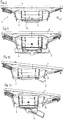
Es hat sich als besonders vorteilhaft herausgestellt, daß das zweite Sitzträgerelement 7 relativ zu dem ersten Sitzträgerelement 6 auf einer Bahnkurve 28 bewegbar ist, die in einer Ebene 29 quer zur Stuhllängsrichtung 8 liegt, wobei es sich bei dieser Ebene 29 vorzugsweise um eine vertikale Ebene (siehe
Besonders vorteilhaft ist es darüber hinaus, wenn sich bei einer Bewegung des zweiten Sitzträgerelements 7 relativ zu dem ersten Sitzträgerelement 6 der von dem zweiten Sitzträgerelement 7 getragene Sitz in Stuhllängsrichtung 8 gesehen seitlich neigt. Die konkrete Ausführung des Sitzes ist dabei für die Erfindung unerheblich.Moreover, it is particularly advantageous if, during a movement of the second
Die Neigebewegung des zweiten Sitzträgerelements 7 umfaßt dabei vorzugsweise eine Translation und eine Rotation. Mit anderen Worten wird eine Seitwärtsbewegung, also eine Bewegung des zweiten Sitzträgerelements 7 quer zur Stuhllängsrichtung 8, mit einer Kipp- bzw. Neigebewegung des zweiten Sitzträgerelements 7 relativ zu dem ersten Sitzträgerelement 6 kombiniert. Alternativ, aber nicht vorzugsweise, erfolgt eine ausschließliche Rotation des zweiten Sitzträgerelements 7, d.h. eine reine Kippbewegung, siehe
In der ersten Ausführungsform (
Derart ausgeführt erfolgt die Verbindung der beiden Sitzträgerelemente 6, 7 miteinander unter Ausbildung einer Viergelenkmechanik, wobei sich für das zweite Sitzträgerelement 7 ein virtueller Drehpunkt 37 (Momentanpol) als Schnittpunkt der beiden durch die Lenker 31, 32 (genauer deren Anlenkpunkte) verlaufenden Geraden ergibt. Durch die Länge der Lenker 31, 32 und/oder die Lage der Anlenkpunkte bzw. Drehachsen 33, 34, 35, 36 an dem ersten und zweiten Sitzträgerelement 6, 7 kann der Abstand des Momentanpols 37 zum Sitzträger 4 je nach gewünschter Bewegungs-/Neigungsdynamik des Sitzes definiert werden.In this way, the connection of the two
Die Lenker 31, 32 sind in dem illustrierten Beispiel als plattenförmige Koppelelemente ausgeführt, wobei die Drehgelenke zur Ankopplung an das erste und zweite Sitzträgerelement 6, 7 an der unteren und oberen Seitenkante der Lenker 31, 32 vorgesehen sind, so daß die Drehachsen 33, 43, 35, 36 parallel zu der Längsrichtung der Lenker 31, 32 verlaufen. Die Anzahl der Lenker 31, 32 auf jeder Seite der Mittellängsebene 25 kann auch größer sein. So ist es je nach konstruktiver Ausführung beispielsweise möglich, daß anstelle eines einzigen Lenkers 31, 32 pro Seite zwei oder drei Lenker pro Seite vorgesehen sind.The
Der Momentanpol 37 befindet sich vorzugsweise unterhalb des Sitzträgers 4, genauer unterhalb der Sitzfläche des Sitzes. Bei der in
Es hat sich als besonders vorteilhaft erwiesen, wenn sich der Momentanpol 37 des Sitzträgers 4 bei einer Bewegung des zweiten Sitzträgerelements 7 quer zur Stuhllängsrichtung 8 stets so weit entfernt von dem Sitzträger 4 befindet, daß die Translationsanteile der Bewegung größer sind als die Rotationsanteile. Der Momentanpol 37 befindet sich außerdem vorzugsweise so weit weg von dem Sitzträger 4, daß die Translationskomponente der Bewegung des zweiten Sitzträgerelements 7 größer ist als die Rotations-/Neigungskomponente der Bewegung. Anders ausgedrückt bewegt sich das zweite Sitzträgerelement 7 auf keiner extrem gekrümmten bzw. steilen, sondern statt dessen auf eine eher flachen Bahnkurve. Das kommt einem erhöhter Sitzkomfort zugute. Vorzugsweise befindet sich der Momentanpol 37 in Bodennähe, also in der Nähe des am unteren Ende der Stuhlsäule vorgesehenen Stuhlträgers (nicht abgebildet).It has proved to be particularly advantageous if the
Der Momentanpol 37 bewegt sich, wie in den
Die durch die Lage der Achsen 33, 34, 35, 36 definierten Anlenkpunkte der beiden Lenker 31, 32 bilden (mit Blick in Stuhllängsrichtung 8) im nicht ausgelenkten Zustand ein symmetrisches, insbesondere gleichschenkeliges Trapez. Dabei bilden die beiden Lenker 31, 32, genauer gesagt die Verbindungslinien 41, 42 zwischen den oberen und unteren Anlenkpunkten (Achslagen), die Trapezschenkel, die Verbindungslinie 43 zwischen den oberen Anlenkpunkten die obere Trapezgrundseite und die Verbindungslinie 44 zwischen den unteren Anlenkpunkten die untere Trapezgrundseite.Defined by the position of the
Aufgrund der Lage der Lenker 31, 32 zum Erreichen eines unterhalb des Sitzträgers 4 angeordneten Momentanpols 37 ist die obere Grundseite des Trapezes länger ist als die untere Grundseite. Anders ausgedrückt ist der Abstand der unteren Achsen, also der Achsen 33, 35 der Gelenke der Verbindung der Lenker 31, 32 mit dem ersten (unteren) Sitzträgerelement 6, geringer als der Abstand der oberen Achsen, also der Achsen 34, 36 der Gelenke der Verbindung der Lenker 31, 32, mit dem zweiten (oberen) Sitzträgerelement 7. Aus diesem Grund handelt es sich um ein labiles System, das zum Kippen neigt. Es ist daher eine Anzahl Federelemente (nicht dargestellt) vorgesehen, die - an geeigneten Stellen angreifend - das zweite Sitzträgerelement 7 im nicht geneigten Grundzustand in Position zu dem ersten Sitzträgerelement 6 hält und im geneigten Zustand ein Rückführen des zweiten Sitzträgerelements 7 in dessen Grundstellung unterstützt bzw. bewirkt. Insbesondere sind Federelemente vorgesehen, die einerseits an dem ersten Sitzträgerelement 6 und andererseits an dem zweiten Sitzträgerelement 7 oder an den Lenkern 31, 32 angebunden sind, um das zweite Sitzträgerelement 7 in seiner nicht nach rechts oder links geneigten Grundstellung zu halten.Due to the position of the
In weiteren Ausführungsformen sind andere Arten der Verbindung der beiden Sitzträgerelemente 6, 7 vorgesehen. In einer zweiten und dritten Ausführungsform (
Es ist aber nicht nur möglich, das erste und das zweite Sitzträgerelement 6, 7 als zwei voneinander getrennte Bauteile auszuführen, die mechanisch miteinander verbunden sind, z.B. über die beschriebenen Koppelelemente (Lenker 31, 32). Alternativ dazu kann zwischen dem ersten und dem zweiten Sitzträgerelement 6, 7 als drittes Bauteil wenigstens ein elastisches Koppelelement (nicht abgebildet) angeordnet sein, beispielsweise in Form eines quader- oder zylinderförmigen Pufferelements, welches die benötigte Bewegbarkeit der beiden Sitzträgerelemente 6, 7 zueinander sicherstellt. Dabei ist das Pufferelement beispielsweise so aufgebaut, daß zwischen einer Grundplatte und einer Deckplatte ein gummielastischer Werkstoff angeordnet ist. Derartige oder ähnliche Pufferelemente können auch zwischen den zueinander bewegbaren Mechanikkomponenten 6, 7 usw. als Anschlagselemente zur Bewegungsbegrenzung vorgesehen sein.However, it is not only possible to design the first and second
Alternativ zu einer mehrteiligen Gestaltung der Sitzträgerelemente 6, 7 (mit oder ohne Pufferelemente) ist auch eine einteilige Ausführung der beiden Sitzträgerelemente 6, 7 möglich, vorzugsweise unter Verwendung von geeignetem, flexiblen bzw. elastischen Verbindungsmaterial, das eine Querbewegung und/oder Neigung des zweiten Sitzträgerelements 7 relativ zu dem ersten Sitzträgerelement 6 erlaubt. Eine solche Variante ist besonders vorteilhaft herstellbar, beispielsweise unter Verwendung eines Mehrkomponenten-Spritzgußverfahrens mit verschiedenen geeigneten Kunststoffen. Die Mechanikkomponenten sind in diesem Fall vorzugsweise rückfedernd konstruiert, d.h. insbesondere zum Zurückführen des bewegten bzw. ausgelenkten Elements in die Grundposition ausgebildet. Die sonst notwendigen Federelemente zum Aufrichten des zweiten Sitzträgerelements 7 bzw. zum Halten des Gleichgewichtszustands des zweiten Sitzträgerelements 7 im unbesetzten Zustand können dann wegfallen.As an alternative to a multi-part design of the
In der in den
Vorzugsweise sind das erste und das zweite Rückenlehnenträgerelement 9, 11 als zwei voneinander getrennte Bauteile ausgeführt, die mechanisch miteinander verbunden sind, z.B. über eine stoßseitige Verbindung mit rotatorischem Freiheitsgrad. Alternativ ist jedoch auch eine einteilige Ausführung der beiden Rückenlehnenträgerelemente 9, 11 möglich, vorzugsweise unter Verwendung von geeignetem, flexiblen bzw. elastischen Verbindungsmaterial, das ein Verdrehen des zweiten Rückenlehnenträgerelements 11 um die Drehachse 12 erlaubt.Preferably, the first and the second
Das zweite Rückenlehnenträgerelement 11 ist vorzugsweise als zentraler Tragarm ausgeführt, der sich mittig nach hinten von der Stuhlmechanik 1 weg erstreckt. Alternativ ist das zweite Rückenlehnenträgerelement 11 als Teil eines Rahmens 50 für die Rückenlehne ausgeführt, beispielsweise als zentrales Verbindungselement zwischen dem Rückenlehnenträger 5 und einer unteren Querstrebe des Rahmens 50.The second
Vorzugsweise ist das zweite Rückenlehnenträgerelement 11 mit dem zweiten Sitzträgerelement 7 derart gekoppelt, daß eine Bewegung des zweiten Sitzträgerelements 7 relativ zu dem ersten Sitzträgerelement 6 eine Bewegung des zweiten Rückenlehnenträgerelements 11 relativ zu dem ersten Rückenlehnenträgerelement 9, genauer eine Neigung des zweiten Rückenlehnenträgerelements 11 nach rechts oder links, bewirkt (oder umgekehrt). Mit anderen Worten findet eine vorteilhafte Kombination der beiden Neigebewegungen statt. Nicht nur der Sitz neigt sich (nach rechts oder links), sondern auch die Rückenlehne. Eine feststehende Rückenlehne wäre bei einem sich neigenden Sitz weniger komfortabel. Die seitliche Neigung des Sitzes bzw. der Rückenlehne (ohne eine Verschwenkung des Sitzträgers 4 nach hinten durch den Rückenlehnenträger 5) ist in den
Die Neigebewegung des Rückenlehnenträgers 5, genauer gesagt die Neigebewegung des zweiten Rückenlehnenträgerelements 11 und damit der Rückenlehne, wird allein und ausschließlich durch die Anlenkung des zweiten Rückenlehnenträgerelements 11 an das zweite Sitzträgerelement 7 induziert.The tilting movement of the
Vorzugsweise erfolgt bei einer Bewegung des zweiten Sitzträgerelements 7 relativ zu dem ersten Sitzträgerelement 6 in Stuhllängsrichtung 8 gesehen eine seitliche Neigung der von dem zweiten Rückenlehnenträgerelement 11 getragenen Rückenlehne. Die konkrete Ausführung der Rückenlehne ist dabei für die Erfindung unerheblich.Preferably, when the second
Bei der in den
Der Verbindungsarm 48 ist dabei vorzugsweise nicht drehfest ausgeführt, d.h. das Freiende 49 liegt drehbar in der Aufnahmeöffnung 51 ein. Das Freiende 49 ist dabei sowohl axial, d.h. in Stuhllängsrichtung 8, als auch vertikal in der Aufnahmeöffnung 51 verschiebbar, so daß sich der Verbindungsarm 48 - entsprechend der kombinierten Translations-/Rotationsbewegung des zweiten Sitzträgerelements 7 auf der definierten Bahnkurve 28 relativ zu dem ersten Sitzträgerelement 6 - mit begrenzten Freiheitsgraden mitbewegen kann derart, daß er eine (reine) Drehbewegung des zweiten Rückenlehnenträgerelements 11 um dessen Drehachse 12 relativ zu dem ersten Rückenlehnenträgerelement 9 bewirkt.The connecting
Realisiert wird diese Ankopplung z.B. durch einen am freien Ende 49 des Verbindungsarmes 48 angebrachten Kulissenstein 52 oder dergleichen, der in der nach Art einer Nut ausgebildeten Kulisse bzw. Aufnahmeöffnung 51 des zweiten Sitzträgerelements 7 (dort an den vertikalen Seitenflächen der Nut anliegend) einliegt. Dabei wird die Bewegung der Kulisse und damit die Bewegung des zweiten Sitzträgerelemente 7 auf den zwangsgeführten Kulissenstein 52 übertragen, wobei der rotatorische Freiheitsgrad durch eine geeignete Drehverbindung des Kulissensteins 52 mit dem Verbindungsarm 48 verwirklicht wird.This coupling is realized, for example, by a sliding
Die Zweiteilung des Rückenlehnenträgers 5 erfolgt dabei so, daß das erste Rückenlehnenträgerelement 9 wie der in Stuhllängsrichtung 8 gesehen vordere Teil des Rückenlehnenträgers 5 die Anbindung der Rückenlehne an den Basisträger 2 und das erste Sitzträgerelement 6 realisiert, während das zweite Rückenlehnenträgerelement 11, welches sich in Stuhllängsrichtung 8 gesehen nach hinten an das erste Rückenlehnenträgerelement 9 anschließt, den Übergang zu der Rückenlehne bildet, zugleich jedoch an das zweite Sitzträgerelement 7 angekoppelt ist.The division of the
Alternativ erfolgt die Verbindung bzw. Ankopplung des zweiten Sitzträgerelements 7 an das zweite Rückenlehnenträgerelement 11 über eine Anzahl mit dem zweiten Sitzträgerelement 7 und dem zweiten Rückenlehnenträgerelement 11 gelenkig verbundene Lenker (nicht abgebildet), die vorzugsweise so ausgeführt sind, wie die Lenker zwischen den beiden Sitzträgerelementen 6, 7 nach Art einer Viergelenkmechanik, oder aber über andere Koppelelemente. Alternativ erfolgt die Verbindung bzw. Ankopplung des zweiten Sitzträgerelements 7 an das zweite Rückenlehnenträgerelement 11 über eine einteilige Ausführung von Sitzträgerelement 7 und Rückenlehnenträgerelement 11 unter Verwendung eines geeigneten, flexiblen bzw. elastischen Materials.Alternatively, the connection or coupling of the second
Als besonders vorteilhaft hat sich eine Variante herausgestellt, bei der die Neigung der Rückenlehne bzw. des zweiten Rückenlehnenträgerelements 11 von der Neigung des Sitzes bzw. des zweiten Sitzträgerelements 7 verschieden ist. Mit der Erfindung ist es also nicht nur möglich, ausschließlich eine Neigebewegung des zweiten Sitzträgerelements 7 nach rechts oder links zu verwirklichen, ohne daß dies zu einer Folgebewegung des Rückenlehnenträgers 5 führt; hierfür muß lediglich die Ankopplung des Rückenlehnenträgers 5 an das zweite Sitzträgerelement 7 entfallen. Die Neigebewegungen der beteiligten Elemente können auch voneinander abweichen. Im einfachsten Fall entspricht zwar die Neigung des zweiten Rückenlehnenträgerelements 11 und damit der Rückenlehne der Neigung des zweiten Sitzträgerelements 7 und damit des Sitzes. Vorzugsweise bewegt sich die Rückenlehne jedoch in einem abweichenden Verhältnis zu dem sich neigenden Sitz, d.h. die beiden Neigungswinkel sind ungleich. Ein ungleiches Neigungsmaß hat sich als besonders benutzerfreundlich herausgestellt, insbesondere dann, wenn einer Neigung des zweiten Sitzträgerelements 7 um einen bestimmten Neigungswinkel eine Neigung des zweiten Rückenlehnenträgerelements 11 um einen größeren Neigungswinkel folgt, wie in den
Vorzugsweise befindet sich die Lage der Drehachse 12 des Rückenlehnenträgers 5 unterhalb des Verbindungspunktes des Freiendes 49 des Verbindungsarmes 48 mit dem Sitzträger 4, also unterhalb des Punktes, an dem der Kulissenstein 52 in der Aufnahmeöffnung 51 einliegt. Dadurch wird erreicht, daß sich die Rückenlehne in die gleiche Richtung neigt, wie der Sitz. Eine gegenläufige Verschenkung der Rückenlehne (Verschwenken in die entgegengesetzte Richtung) kann entsprechend durch eine umgekehrte Anordnung dieser beiden Punkte zueinander erreicht werden.Preferably, the position of the axis of
Je weiter der Momentanpol 37 des zweiten Sitzträgerelements 7 von der ortsfesten Drehachse 12 des Rückenlehnenträgers 5 entfernt ist, desto größer ist die Abweichung der Neigungsbewegung des zweiten Rückenlehnenträgerelements 11 zu der des zweiten Sitzträgerelements 7. Es kann somit das gewünschte Neigungsverhältnis zwischen Sitz und Rückenlehne eingestellt werden, insbesondere durch die konstruktive Anordnung der Lage der Achsen 33, 34, 35, 36, durch die definierte Einstellung der Abstände der Achsen 33, 34, 35, 36 zueinander und/oder durch die Anordnung der realen und virtuellen Drehpunkte 37 der beteiligten Komponenten der Stuhlmechanik 1.The farther the
Als besonders vorteilhaft gilt eine Variante der Erfindung, bei welcher der Rückenlehnenträger 5, genauer das erste Rückenlehnenträgerelement 9, mit dem Sitzträger 4, genauer mit dem ersten Sitzträgerelement 6, derart gekoppelt ist, daß ein Verschwenken des Rückenlehnenträgers 5 in Stuhllängsrichtung 8 eine Bewegung des Sitzträgers 4 in Stuhllängsrichtung 8 um eine quer zur Stuhllängsrichtung 8 verlaufende Schwenkachse relativ zu dem Basisträger 2 bewirkt ("Synchronmechanik"). Anstelle einer solchen klassischen Synchronmechanik können von der Stuhlmechanik 1, die mit der Erfindung versehen wird, aber auch andere Mechaniktypen verwirklicht sein, wie Asynchronmechaniken, Wippmechaniken oder Mischtypen.Particularly advantageous is a variant of the invention in which the
Dabei ist die (Neige-) Bewegung des zweiten Sitzträgerelements 7 relativ zu dem ersten Sitzträgerelement 6 unabhängig von einer sonstigen Bewegung des Sitzträgers 4 in Stuhllängsrichtung 8, insbesondere unabhängig von der von dem Rückenlehnenträger 5 bewirkten (Schwenk-)Bewegung des Sitzträgers 4. Erreicht wird diese konstruktive und funktionale Unabhängigkeit der Bewegungen durch die Trennung des Sitzträgers 4 in die zwei Sitzträgerelemente 6, 7. Beide Bewegungen sind unabhängig voneinander, d.h. nicht aneinander gekoppelt, möglich, auch einander überlagernd. Beispielsweise wird unabhängig von einer Neigebewegung des zweiten Sitzträgerelements 7 nach rechts oder links der gesamte Sitzträger 4 bei einem Verschwenken des Rückenlehnenträgers 5 nach hinten mitgenommen und eine Neigebewegung des zweiten Sitzträgerelements 7 nach rechts und links kann im nichtverschwenkten Zustand der Mechanik 1 oder aber auch zusätzlich zu einem Verschwenken der Rückenlehne erfolgen.In this case, the (tilting) movement of the second
Illustriert wird dies beispielhaft in den
Gegenüber einer herkömmlichen Stuhlmechanik wird mit der Erfindung die Anzahl der Freiheitsgrade erhöht, indem für den Sitzträger 4 und optionale auch für den Rückenlehnenträger 5 weitere Freiheitsgrade vorgesehen werden. Es ergibt sich gegenüber herkömmlichen Lösungen ein verbessertes Bewegungsverhalten des Stuhls auf Bewegungen des Benutzers. Alle in der Beschreibung, den nachfolgenden Ansprüchen und der Zeichnung dargestellten Merkmale können sowohl einzeln als auch in beliebiger Kombination miteinander erfindungswesentlich sein.Compared to a conventional chair mechanism, the invention increases the number of degrees of freedom by providing more degrees of freedom for the seat support 4 and optionally also for the
- 11
- Mechanikmechanics
- 22
- Basisträgerbase support
- 33
- Konusaufnahmecone holder
- 44
- Sitzträgerseat support
- 55
- RückenlehnenträgerBackrest support
- 66
- erstes Sitzträgerelementfirst seat support element
- 77
- zweites Sitzträgerelementsecond seat support element
- 88th
- StuhllängsrichtungChair longitudinally
- 99
- erstes Rückenlehnenträgerelementfirst backrest support element
- 1010
- (frei)(free)
- 1111
- zweites Rückenlehnenträgerelementsecond backrest support element
- 1212
- Drehachse des RückenlehnenträgersRotary axis of the backrest support
- 1313
- hinteres Ende des ersten Sitzträgerelementsrear end of the first seat support member
- 1414
- hinteres Ende des BasisträgersRear end of the basic carrier
- 1515
- hintere Drehachserear axis of rotation
- 1616
- hintere Drehachserear axis of rotation
- 1717
- hinteres Koppelelementrear coupling element
- 1818
- vorderes Koppelelementfront coupling element
- 1919
- vorderes Ende des ersten Sitzträgerelementsfront end of the first seat support member
- 2020
- (frei)(free)
- 2121
- vorderes Ende des Basisträgersfront end of the basic carrier
- 2222
- vordere Drehachsefront axis of rotation
- 2323
- vordere Drehachsefront axis of rotation
- 2424
- Schwenkrichtungpan direction
- 2525
- MittellängsebeneCentral longitudinal plane
- 2626
- StuhlvorderseiteChair front
- 2727
- StuhlhinterseiteChair back
- 2828
- Bahnkurvetrajectory
- 2929
- Ebene der BahnkurvePlane of the trajectory
- 3030
- (frei)(free)
- 3131
- erster Lenkerfirst handlebar
- 3232
- zweiter Lenkersecond handlebar
- 3333
- erste Drehachse des ersten Lenkersfirst axis of rotation of the first link
- 3434
- zweite Drehachse des ersten Lenkerssecond axis of rotation of the first link
- 3535
- erste Drehachse des zweiten Lenkersfirst axis of rotation of the second link
- 3636
- zweite Drehachse des zweiten Lenkerssecond axis of rotation of the second link
- 3737
- virtueller Drehpunkt, Momentanpolvirtual pivot point, momentary pole
- 3838
- Bahnkurve des MomentanpolsTrajectory of the instantaneous pole
- 3939
- (frei)(free)
- 4040
- (frei)(free)
- 4141
- vertikale Verbindungslinievertical connecting line
- 4242
- vertikale Verbindungslinievertical connecting line
- 4343
- horizontale Verbindungsliniehorizontal connecting line
- 4444
- horizontale Verbindungsliniehorizontal connecting line
- 4545
- Oberfläche des ersten Sitzträgerelements, Roll-/GleitbahnSurface of the first seat support element, rolling / sliding track
- 4646
- Kugellagerball-bearing
- 4747
- Oberfläche des zweiten SitzträgerelementsSurface of the second seat support element
- 4848
- Verbindungsarmconnecting arm
- 4949
- Freiendefree end
- 5050
- Rahmenframe
- 5151
- Aufnahmeöffnungreceiving opening
- 5252
- Kulissensteinsliding block
Claims (14)
mit einem auf einer Stuhlsäule plazierbaren Basisträger (2), mit einem auf dem Basisträger (2) angeordneten, relativ zu dem Basisträger (2) in Stuhllängsrichtung (8) bewegbaren Sitzträger (4),
und mit einem mit dem Sitzträger (4) verbundenen Rückenlehnenträger (5),
dadurch gekennzeichnet,
with a base support (2) placeable on a chair column, with a seat support (4) arranged on the base support (2) and movable relative to the base support (2) in the chair longitudinal direction (8),
and a backrest support (5) connected to the seat support (4),
characterized,
Applications Claiming Priority (2)
| Application Number | Priority Date | Filing Date | Title |
|---|---|---|---|
| DE102017100117 | 2017-01-04 | ||
| DE202017102909.3U DE202017102909U1 (en) | 2017-01-04 | 2017-05-15 | Chair with one-piece seat shell |
Publications (2)
| Publication Number | Publication Date |
|---|---|
| EP3345507A1 true EP3345507A1 (en) | 2018-07-11 |
| EP3345507B1 EP3345507B1 (en) | 2020-04-29 |
Family
ID=62026929
Family Applications (2)
| Application Number | Title | Priority Date | Filing Date |
|---|---|---|---|
| EP18150177.6A Active EP3345508B1 (en) | 2017-01-04 | 2018-01-03 | Seat with one-piece seat shell |
| EP18000037.4A Active EP3345507B1 (en) | 2017-01-04 | 2018-01-04 | Mechanism for a chair |
Family Applications Before (1)
| Application Number | Title | Priority Date | Filing Date |
|---|---|---|---|
| EP18150177.6A Active EP3345508B1 (en) | 2017-01-04 | 2018-01-03 | Seat with one-piece seat shell |
Country Status (3)
| Country | Link |
|---|---|
| US (1) | US10499742B2 (en) |
| EP (2) | EP3345508B1 (en) |
| DE (1) | DE202017102909U1 (en) |
Cited By (2)
| Publication number | Priority date | Publication date | Assignee | Title |
|---|---|---|---|---|
| US10881208B2 (en) * | 2016-02-23 | 2021-01-05 | Kokuyo Co., Ltd. | Chair and seat support mechanism |
| DE102020124975A1 (en) | 2020-09-24 | 2022-03-24 | Bock 1 Gmbh & Co. Kg | Mechanism for a chair |
Families Citing this family (1)
| Publication number | Priority date | Publication date | Assignee | Title |
|---|---|---|---|---|
| US10702066B2 (en) * | 2018-11-19 | 2020-07-07 | Profim SP. ZO.O | Office chair |
Citations (4)
| Publication number | Priority date | Publication date | Assignee | Title |
|---|---|---|---|---|
| DE202012012606U1 (en) * | 2011-05-04 | 2013-06-12 | Eckhard Hansen | seating |
| DE102012107778A1 (en) * | 2012-08-23 | 2014-06-26 | Haworth Gmbh | Chair, especially office chair |
| DE202014101592U1 (en) * | 2014-04-04 | 2014-06-30 | Wilkhahn Wilkening + Hahne Gmbh + Co. | chair |
| DE102014103780B3 (en) * | 2014-03-19 | 2015-06-18 | Wilkhahn Wilkening + Hahne Gmbh + Co. | chair |
Family Cites Families (11)
| Publication number | Priority date | Publication date | Assignee | Title |
|---|---|---|---|---|
| CH666171A5 (en) * | 1984-10-03 | 1988-07-15 | Giroflex Entwicklungs Ag | CHAIR WITH REAR TILTABLE SEAT AND BACKREST CARRIER. |
| US5538326A (en) * | 1994-11-14 | 1996-07-23 | Milsco Manufacturing Company | Flexible unitary seat shell |
| US6523898B1 (en) * | 1999-06-17 | 2003-02-25 | Steelcase Development Corporation | Chair construction |
| DE10106791A1 (en) * | 2001-02-12 | 2002-08-14 | Sdm Hansen Gmbh St Margrethen | Chair has seat which is mounted on three springs arranged in triangle which are connected to support frame, back rest being mounted so that it can rotate about its longitudinal axis |
| ITMI20022194A1 (en) * | 2002-10-16 | 2004-04-17 | Icf Spa | CHAIR WITH SEAT AND FURNITURE BACK. |
| EP2001338B1 (en) * | 2006-03-24 | 2016-10-26 | Herman Miller Inc. | Body support structure |
| DE102008011309B3 (en) * | 2008-02-27 | 2009-06-04 | Thonet Gmbh | office chair |
| NO328092B1 (en) * | 2008-03-10 | 2009-12-07 | Efg Europ Furniture Group Ab | Rygge Stott device |
| DE202012002288U1 (en) * | 2012-03-08 | 2012-05-11 | Walter Knoll Ag & Co. Kg | functional chair |
| CN103889274A (en) * | 2012-10-18 | 2014-06-25 | 株式会社冈村制作所 | Chair |
| DE102014119612A1 (en) * | 2014-12-23 | 2016-06-23 | Recaro Aircraft Seating Gmbh & Co. Kg | Seat device with longitudinally divided seat bottom unit |
-
2017
- 2017-05-15 DE DE202017102909.3U patent/DE202017102909U1/en not_active Expired - Lifetime
-
2018
- 2018-01-03 EP EP18150177.6A patent/EP3345508B1/en active Active
- 2018-01-04 US US15/861,714 patent/US10499742B2/en active Active
- 2018-01-04 EP EP18000037.4A patent/EP3345507B1/en active Active
Patent Citations (4)
| Publication number | Priority date | Publication date | Assignee | Title |
|---|---|---|---|---|
| DE202012012606U1 (en) * | 2011-05-04 | 2013-06-12 | Eckhard Hansen | seating |
| DE102012107778A1 (en) * | 2012-08-23 | 2014-06-26 | Haworth Gmbh | Chair, especially office chair |
| DE102014103780B3 (en) * | 2014-03-19 | 2015-06-18 | Wilkhahn Wilkening + Hahne Gmbh + Co. | chair |
| DE202014101592U1 (en) * | 2014-04-04 | 2014-06-30 | Wilkhahn Wilkening + Hahne Gmbh + Co. | chair |
Cited By (3)
| Publication number | Priority date | Publication date | Assignee | Title |
|---|---|---|---|---|
| US10881208B2 (en) * | 2016-02-23 | 2021-01-05 | Kokuyo Co., Ltd. | Chair and seat support mechanism |
| DE102020124975A1 (en) | 2020-09-24 | 2022-03-24 | Bock 1 Gmbh & Co. Kg | Mechanism for a chair |
| EP3973820A1 (en) | 2020-09-24 | 2022-03-30 | BOCK 1 GmbH & Co. KG | Mechanism for a chair |
Also Published As
| Publication number | Publication date |
|---|---|
| US10499742B2 (en) | 2019-12-10 |
| DE202017102909U1 (en) | 2018-04-05 |
| EP3345507B1 (en) | 2020-04-29 |
| US20180184809A1 (en) | 2018-07-05 |
| EP3345508B1 (en) | 2020-06-17 |
| EP3345508A1 (en) | 2018-07-11 |
Similar Documents
| Publication | Publication Date | Title |
|---|---|---|
| EP1946676B1 (en) | Chair | |
| DE19646470B4 (en) | Motor vehicle seat with a backrest and a seat | |
| EP1060694B1 (en) | Chair, particularly office-chair | |
| DE102015101546B4 (en) | synchronous mechanism | |
| EP2801293B1 (en) | Seating furniture and cover for same | |
| WO2011141107A1 (en) | Adjusting mechanism for adjusting a restoring force that acts on a backrest of a chair, and office chair with such an adjusting mechanism | |
| AT12867U1 (en) | seating | |
| EP3345507B1 (en) | Mechanism for a chair | |
| EP1652505B1 (en) | Treatment chair, particularly dental treatment chair | |
| EP3120732B1 (en) | Mechanism for an office chair | |
| WO2006074763A1 (en) | Piece of furniture in particular a seat | |
| EP3387957A1 (en) | Synchronising mechanism for an office chair | |
| WO2016124317A1 (en) | Synchronized mechanism | |
| EP3973820A1 (en) | Mechanism for a chair | |
| EP1992255A1 (en) | Seating | |
| EP3437519B1 (en) | Rocking mechanism | |
| EP2477523B1 (en) | Tilting mechanism for an office chair | |
| EP2994017B1 (en) | Synchronizing mechanism | |
| EP3253255B1 (en) | Synchronized mechanism | |
| DE102019113581A1 (en) | Synchronous mechanism | |
| WO2014177445A1 (en) | Chair with seat mechanism | |
| DE102019113582B4 (en) | synchronous mechanism | |
| EP3528664A1 (en) | Synchronous chair mechanism and chair having one such | |
| EP3253254B1 (en) | Synchronized mechanism | |
| WO2024013141A1 (en) | Synchronizing mechanism for a chair |
Legal Events
| Date | Code | Title | Description |
|---|---|---|---|
| PUAI | Public reference made under article 153(3) epc to a published international application that has entered the european phase |
Free format text: ORIGINAL CODE: 0009012 |
|
| STAA | Information on the status of an ep patent application or granted ep patent |
Free format text: STATUS: THE APPLICATION HAS BEEN PUBLISHED |
|
| AK | Designated contracting states |
Kind code of ref document: A1 Designated state(s): AL AT BE BG CH CY CZ DE DK EE ES FI FR GB GR HR HU IE IS IT LI LT LU LV MC MK MT NL NO PL PT RO RS SE SI SK SM TR |
|
| AX | Request for extension of the european patent |
Extension state: BA ME |
|
| STAA | Information on the status of an ep patent application or granted ep patent |
Free format text: STATUS: REQUEST FOR EXAMINATION WAS MADE |
|
| 17P | Request for examination filed |
Effective date: 20181219 |
|
| RBV | Designated contracting states (corrected) |
Designated state(s): AL AT BE BG CH CY CZ DE DK EE ES FI FR GB GR HR HU IE IS IT LI LT LU LV MC MK MT NL NO PL PT RO RS SE SI SK SM TR |
|
| STAA | Information on the status of an ep patent application or granted ep patent |
Free format text: STATUS: EXAMINATION IS IN PROGRESS |
|
| 17Q | First examination report despatched |
Effective date: 20190301 |
|
| GRAP | Despatch of communication of intention to grant a patent |
Free format text: ORIGINAL CODE: EPIDOSNIGR1 |
|
| STAA | Information on the status of an ep patent application or granted ep patent |
Free format text: STATUS: GRANT OF PATENT IS INTENDED |
|
| INTG | Intention to grant announced |
Effective date: 20191212 |
|
| GRAS | Grant fee paid |
Free format text: ORIGINAL CODE: EPIDOSNIGR3 |
|
| GRAA | (expected) grant |
Free format text: ORIGINAL CODE: 0009210 |
|
| STAA | Information on the status of an ep patent application or granted ep patent |
Free format text: STATUS: THE PATENT HAS BEEN GRANTED |
|
| AK | Designated contracting states |
Kind code of ref document: B1 Designated state(s): AL AT BE BG CH CY CZ DE DK EE ES FI FR GB GR HR HU IE IS IT LI LT LU LV MC MK MT NL NO PL PT RO RS SE SI SK SM TR |
|
| REG | Reference to a national code |
Ref country code: GB Ref legal event code: FG4D Free format text: NOT ENGLISH |
|
| REG | Reference to a national code |
Ref country code: CH Ref legal event code: EP |
|
| REG | Reference to a national code |
Ref country code: DE Ref legal event code: R096 Ref document number: 502018001277 Country of ref document: DE |
|
| REG | Reference to a national code |
Ref country code: AT Ref legal event code: REF Ref document number: 1262029 Country of ref document: AT Kind code of ref document: T Effective date: 20200515 |
|
| REG | Reference to a national code |
Ref country code: IE Ref legal event code: FG4D Free format text: LANGUAGE OF EP DOCUMENT: GERMAN |
|
| REG | Reference to a national code |
Ref country code: NL Ref legal event code: MP Effective date: 20200429 |
|
| REG | Reference to a national code |
Ref country code: LT Ref legal event code: MG4D |
|
| PG25 | Lapsed in a contracting state [announced via postgrant information from national office to epo] |
Ref country code: GR Free format text: LAPSE BECAUSE OF FAILURE TO SUBMIT A TRANSLATION OF THE DESCRIPTION OR TO PAY THE FEE WITHIN THE PRESCRIBED TIME-LIMIT Effective date: 20200730 Ref country code: SE Free format text: LAPSE BECAUSE OF FAILURE TO SUBMIT A TRANSLATION OF THE DESCRIPTION OR TO PAY THE FEE WITHIN THE PRESCRIBED TIME-LIMIT Effective date: 20200429 Ref country code: PT Free format text: LAPSE BECAUSE OF FAILURE TO SUBMIT A TRANSLATION OF THE DESCRIPTION OR TO PAY THE FEE WITHIN THE PRESCRIBED TIME-LIMIT Effective date: 20200831 Ref country code: LT Free format text: LAPSE BECAUSE OF FAILURE TO SUBMIT A TRANSLATION OF THE DESCRIPTION OR TO PAY THE FEE WITHIN THE PRESCRIBED TIME-LIMIT Effective date: 20200429 Ref country code: FI Free format text: LAPSE BECAUSE OF FAILURE TO SUBMIT A TRANSLATION OF THE DESCRIPTION OR TO PAY THE FEE WITHIN THE PRESCRIBED TIME-LIMIT Effective date: 20200429 Ref country code: IS Free format text: LAPSE BECAUSE OF FAILURE TO SUBMIT A TRANSLATION OF THE DESCRIPTION OR TO PAY THE FEE WITHIN THE PRESCRIBED TIME-LIMIT Effective date: 20200829 Ref country code: NO Free format text: LAPSE BECAUSE OF FAILURE TO SUBMIT A TRANSLATION OF THE DESCRIPTION OR TO PAY THE FEE WITHIN THE PRESCRIBED TIME-LIMIT Effective date: 20200729 |
|
| REG | Reference to a national code |
Ref country code: CH Ref legal event code: PK Free format text: BERICHTIGUNGEN |
|
| PG25 | Lapsed in a contracting state [announced via postgrant information from national office to epo] |
Ref country code: RS Free format text: LAPSE BECAUSE OF FAILURE TO SUBMIT A TRANSLATION OF THE DESCRIPTION OR TO PAY THE FEE WITHIN THE PRESCRIBED TIME-LIMIT Effective date: 20200429 Ref country code: HR Free format text: LAPSE BECAUSE OF FAILURE TO SUBMIT A TRANSLATION OF THE DESCRIPTION OR TO PAY THE FEE WITHIN THE PRESCRIBED TIME-LIMIT Effective date: 20200429 Ref country code: LV Free format text: LAPSE BECAUSE OF FAILURE TO SUBMIT A TRANSLATION OF THE DESCRIPTION OR TO PAY THE FEE WITHIN THE PRESCRIBED TIME-LIMIT Effective date: 20200429 Ref country code: BG Free format text: LAPSE BECAUSE OF FAILURE TO SUBMIT A TRANSLATION OF THE DESCRIPTION OR TO PAY THE FEE WITHIN THE PRESCRIBED TIME-LIMIT Effective date: 20200729 |
|
| RIN2 | Information on inventor provided after grant (corrected) |
Inventor name: BOCK, HERMANN Inventor name: BALLENDAT, MARTIN |
|
| PG25 | Lapsed in a contracting state [announced via postgrant information from national office to epo] |
Ref country code: AL Free format text: LAPSE BECAUSE OF FAILURE TO SUBMIT A TRANSLATION OF THE DESCRIPTION OR TO PAY THE FEE WITHIN THE PRESCRIBED TIME-LIMIT Effective date: 20200429 Ref country code: NL Free format text: LAPSE BECAUSE OF FAILURE TO SUBMIT A TRANSLATION OF THE DESCRIPTION OR TO PAY THE FEE WITHIN THE PRESCRIBED TIME-LIMIT Effective date: 20200429 |
|
| PG25 | Lapsed in a contracting state [announced via postgrant information from national office to epo] |
Ref country code: ES Free format text: LAPSE BECAUSE OF FAILURE TO SUBMIT A TRANSLATION OF THE DESCRIPTION OR TO PAY THE FEE WITHIN THE PRESCRIBED TIME-LIMIT Effective date: 20200429 Ref country code: DK Free format text: LAPSE BECAUSE OF FAILURE TO SUBMIT A TRANSLATION OF THE DESCRIPTION OR TO PAY THE FEE WITHIN THE PRESCRIBED TIME-LIMIT Effective date: 20200429 Ref country code: SM Free format text: LAPSE BECAUSE OF FAILURE TO SUBMIT A TRANSLATION OF THE DESCRIPTION OR TO PAY THE FEE WITHIN THE PRESCRIBED TIME-LIMIT Effective date: 20200429 Ref country code: EE Free format text: LAPSE BECAUSE OF FAILURE TO SUBMIT A TRANSLATION OF THE DESCRIPTION OR TO PAY THE FEE WITHIN THE PRESCRIBED TIME-LIMIT Effective date: 20200429 Ref country code: CZ Free format text: LAPSE BECAUSE OF FAILURE TO SUBMIT A TRANSLATION OF THE DESCRIPTION OR TO PAY THE FEE WITHIN THE PRESCRIBED TIME-LIMIT Effective date: 20200429 Ref country code: RO Free format text: LAPSE BECAUSE OF FAILURE TO SUBMIT A TRANSLATION OF THE DESCRIPTION OR TO PAY THE FEE WITHIN THE PRESCRIBED TIME-LIMIT Effective date: 20200429 |
|
| REG | Reference to a national code |
Ref country code: DE Ref legal event code: R097 Ref document number: 502018001277 Country of ref document: DE |
|
| PG25 | Lapsed in a contracting state [announced via postgrant information from national office to epo] |
Ref country code: SK Free format text: LAPSE BECAUSE OF FAILURE TO SUBMIT A TRANSLATION OF THE DESCRIPTION OR TO PAY THE FEE WITHIN THE PRESCRIBED TIME-LIMIT Effective date: 20200429 Ref country code: PL Free format text: LAPSE BECAUSE OF FAILURE TO SUBMIT A TRANSLATION OF THE DESCRIPTION OR TO PAY THE FEE WITHIN THE PRESCRIBED TIME-LIMIT Effective date: 20200429 |
|
| PLBE | No opposition filed within time limit |
Free format text: ORIGINAL CODE: 0009261 |
|
| STAA | Information on the status of an ep patent application or granted ep patent |
Free format text: STATUS: NO OPPOSITION FILED WITHIN TIME LIMIT |
|
| 26N | No opposition filed |
Effective date: 20210201 |
|
| PG25 | Lapsed in a contracting state [announced via postgrant information from national office to epo] |
Ref country code: SI Free format text: LAPSE BECAUSE OF FAILURE TO SUBMIT A TRANSLATION OF THE DESCRIPTION OR TO PAY THE FEE WITHIN THE PRESCRIBED TIME-LIMIT Effective date: 20200429 |
|
| PG25 | Lapsed in a contracting state [announced via postgrant information from national office to epo] |
Ref country code: MC Free format text: LAPSE BECAUSE OF FAILURE TO SUBMIT A TRANSLATION OF THE DESCRIPTION OR TO PAY THE FEE WITHIN THE PRESCRIBED TIME-LIMIT Effective date: 20200429 |
|
| REG | Reference to a national code |
Ref country code: CH Ref legal event code: PL |
|
| PG25 | Lapsed in a contracting state [announced via postgrant information from national office to epo] |
Ref country code: LU Free format text: LAPSE BECAUSE OF NON-PAYMENT OF DUE FEES Effective date: 20210104 |
|
| REG | Reference to a national code |
Ref country code: BE Ref legal event code: MM Effective date: 20210131 |
|
| PG25 | Lapsed in a contracting state [announced via postgrant information from national office to epo] |
Ref country code: FR Free format text: LAPSE BECAUSE OF NON-PAYMENT OF DUE FEES Effective date: 20210131 |
|
| PG25 | Lapsed in a contracting state [announced via postgrant information from national office to epo] |
Ref country code: LI Free format text: LAPSE BECAUSE OF NON-PAYMENT OF DUE FEES Effective date: 20210131 Ref country code: CH Free format text: LAPSE BECAUSE OF NON-PAYMENT OF DUE FEES Effective date: 20210131 |
|
| PG25 | Lapsed in a contracting state [announced via postgrant information from national office to epo] |
Ref country code: IE Free format text: LAPSE BECAUSE OF NON-PAYMENT OF DUE FEES Effective date: 20210104 |
|
| PG25 | Lapsed in a contracting state [announced via postgrant information from national office to epo] |
Ref country code: BE Free format text: LAPSE BECAUSE OF NON-PAYMENT OF DUE FEES Effective date: 20210131 |
|
| PGFP | Annual fee paid to national office [announced via postgrant information from national office to epo] |
Ref country code: IT Payment date: 20221206 Year of fee payment: 6 Ref country code: DE Payment date: 20230104 Year of fee payment: 6 |
|
| PG25 | Lapsed in a contracting state [announced via postgrant information from national office to epo] |
Ref country code: CY Free format text: LAPSE BECAUSE OF FAILURE TO SUBMIT A TRANSLATION OF THE DESCRIPTION OR TO PAY THE FEE WITHIN THE PRESCRIBED TIME-LIMIT Effective date: 20200429 |
|
| PG25 | Lapsed in a contracting state [announced via postgrant information from national office to epo] |
Ref country code: HU Free format text: LAPSE BECAUSE OF FAILURE TO SUBMIT A TRANSLATION OF THE DESCRIPTION OR TO PAY THE FEE WITHIN THE PRESCRIBED TIME-LIMIT; INVALID AB INITIO Effective date: 20180104 |
|
| PGFP | Annual fee paid to national office [announced via postgrant information from national office to epo] |
Ref country code: GB Payment date: 20231128 Year of fee payment: 7 |
|
| REG | Reference to a national code |
Ref country code: AT Ref legal event code: MM01 Ref document number: 1262029 Country of ref document: AT Kind code of ref document: T Effective date: 20230104 |
|
| PG25 | Lapsed in a contracting state [announced via postgrant information from national office to epo] |
Ref country code: AT Free format text: LAPSE BECAUSE OF NON-PAYMENT OF DUE FEES Effective date: 20230104 |