EP3344509B1 - Schienenfahrzeugbaugruppe - Google Patents
Schienenfahrzeugbaugruppe Download PDFInfo
- Publication number
- EP3344509B1 EP3344509B1 EP16781740.2A EP16781740A EP3344509B1 EP 3344509 B1 EP3344509 B1 EP 3344509B1 EP 16781740 A EP16781740 A EP 16781740A EP 3344509 B1 EP3344509 B1 EP 3344509B1
- Authority
- EP
- European Patent Office
- Prior art keywords
- rail vehicle
- fiber
- plastic composite
- area
- vehicle assembly
- Prior art date
- Legal status (The legal status is an assumption and is not a legal conclusion. Google has not performed a legal analysis and makes no representation as to the accuracy of the status listed.)
- Active
Links
- 239000002131 composite material Substances 0.000 claims description 43
- 230000003014 reinforcing effect Effects 0.000 claims description 4
- 238000004519 manufacturing process Methods 0.000 claims description 3
- 229920002430 Fibre-reinforced plastic Polymers 0.000 claims 4
- 239000011151 fibre-reinforced plastic Substances 0.000 claims 4
- 239000004033 plastic Substances 0.000 description 44
- 229920003023 plastic Polymers 0.000 description 44
- 230000000712 assembly Effects 0.000 description 8
- 238000000429 assembly Methods 0.000 description 8
- 239000000835 fiber Substances 0.000 description 8
- 239000011347 resin Substances 0.000 description 6
- 229920005989 resin Polymers 0.000 description 6
- 238000000034 method Methods 0.000 description 5
- 238000005516 engineering process Methods 0.000 description 3
- 239000002184 metal Substances 0.000 description 3
- 238000003466 welding Methods 0.000 description 3
- 239000002657 fibrous material Substances 0.000 description 2
- 238000005304 joining Methods 0.000 description 2
- 239000010410 layer Substances 0.000 description 2
- 239000000463 material Substances 0.000 description 2
- 230000002787 reinforcement Effects 0.000 description 2
- 229920000049 Carbon (fiber) Polymers 0.000 description 1
- 239000000853 adhesive Substances 0.000 description 1
- 238000004026 adhesive bonding Methods 0.000 description 1
- 230000001070 adhesive effect Effects 0.000 description 1
- 229920006231 aramid fiber Polymers 0.000 description 1
- 230000005540 biological transmission Effects 0.000 description 1
- 239000004917 carbon fiber Substances 0.000 description 1
- 238000005253 cladding Methods 0.000 description 1
- 238000010276 construction Methods 0.000 description 1
- 239000012792 core layer Substances 0.000 description 1
- 230000000694 effects Effects 0.000 description 1
- 239000003822 epoxy resin Substances 0.000 description 1
- 239000005007 epoxy-phenolic resin Substances 0.000 description 1
- 239000004744 fabric Substances 0.000 description 1
- 239000011152 fibreglass Substances 0.000 description 1
- 239000003365 glass fiber Substances 0.000 description 1
- LNEPOXFFQSENCJ-UHFFFAOYSA-N haloperidol Chemical compound C1CC(O)(C=2C=CC(Cl)=CC=2)CCN1CCCC(=O)C1=CC=C(F)C=C1 LNEPOXFFQSENCJ-UHFFFAOYSA-N 0.000 description 1
- 238000003780 insertion Methods 0.000 description 1
- 230000037431 insertion Effects 0.000 description 1
- VNWKTOKETHGBQD-UHFFFAOYSA-N methane Chemical compound C VNWKTOKETHGBQD-UHFFFAOYSA-N 0.000 description 1
- 239000004745 nonwoven fabric Substances 0.000 description 1
- 229920001568 phenolic resin Polymers 0.000 description 1
- 229920000647 polyepoxide Polymers 0.000 description 1
- 229920001225 polyester resin Polymers 0.000 description 1
- 239000004645 polyester resin Substances 0.000 description 1
Images


Classifications
-
- B—PERFORMING OPERATIONS; TRANSPORTING
- B61—RAILWAYS
- B61D—BODY DETAILS OR KINDS OF RAILWAY VEHICLES
- B61D17/00—Construction details of vehicle bodies
- B61D17/005—Construction details of vehicle bodies with bodies characterised by use of plastics materials
-
- B—PERFORMING OPERATIONS; TRANSPORTING
- B29—WORKING OF PLASTICS; WORKING OF SUBSTANCES IN A PLASTIC STATE IN GENERAL
- B29C—SHAPING OR JOINING OF PLASTICS; SHAPING OF MATERIAL IN A PLASTIC STATE, NOT OTHERWISE PROVIDED FOR; AFTER-TREATMENT OF THE SHAPED PRODUCTS, e.g. REPAIRING
- B29C70/00—Shaping composites, i.e. plastics material comprising reinforcements, fillers or preformed parts, e.g. inserts
- B29C70/04—Shaping composites, i.e. plastics material comprising reinforcements, fillers or preformed parts, e.g. inserts comprising reinforcements only, e.g. self-reinforcing plastics
- B29C70/28—Shaping operations therefor
- B29C70/40—Shaping or impregnating by compression not applied
- B29C70/42—Shaping or impregnating by compression not applied for producing articles of definite length, i.e. discrete articles
- B29C70/46—Shaping or impregnating by compression not applied for producing articles of definite length, i.e. discrete articles using matched moulds, e.g. for deforming sheet moulding compounds [SMC] or prepregs
- B29C70/48—Shaping or impregnating by compression not applied for producing articles of definite length, i.e. discrete articles using matched moulds, e.g. for deforming sheet moulding compounds [SMC] or prepregs and impregnating the reinforcements in the closed mould, e.g. resin transfer moulding [RTM], e.g. by vacuum
-
- B—PERFORMING OPERATIONS; TRANSPORTING
- B29—WORKING OF PLASTICS; WORKING OF SUBSTANCES IN A PLASTIC STATE IN GENERAL
- B29C—SHAPING OR JOINING OF PLASTICS; SHAPING OF MATERIAL IN A PLASTIC STATE, NOT OTHERWISE PROVIDED FOR; AFTER-TREATMENT OF THE SHAPED PRODUCTS, e.g. REPAIRING
- B29C70/00—Shaping composites, i.e. plastics material comprising reinforcements, fillers or preformed parts, e.g. inserts
- B29C70/68—Shaping composites, i.e. plastics material comprising reinforcements, fillers or preformed parts, e.g. inserts by incorporating or moulding on preformed parts, e.g. inserts or layers, e.g. foam blocks
- B29C70/74—Moulding material on a relatively small portion of the preformed part, e.g. outsert moulding
- B29C70/76—Moulding on edges or extremities of the preformed part
-
- B—PERFORMING OPERATIONS; TRANSPORTING
- B29—WORKING OF PLASTICS; WORKING OF SUBSTANCES IN A PLASTIC STATE IN GENERAL
- B29L—INDEXING SCHEME ASSOCIATED WITH SUBCLASS B29C, RELATING TO PARTICULAR ARTICLES
- B29L2031/00—Other particular articles
- B29L2031/06—Rods, e.g. connecting rods, rails, stakes
Definitions
- the invention relates to a rail vehicle assembly, in particular one made of a fiber-plastic composite.
- the support structures of rail vehicles are usually made of metal, which means that although proven manufacturing and connection technologies can be used, the vehicles are heavier than plastics.
- Plastics are used almost exclusively for interior cladding in passenger areas and as shape-defining design components on the end face. While in other means of transport such as aircraft or motor vehicles the use of plastics, in particular fiber-plastic composite materials (glass fiber reinforced plastic GfK) is common, these light materials are used in rail vehicles mainly because of the lack of or insufficient joining technology between the plastic parts, e.g. a side wall and metallic ones Assemblies, e.g. a subframe, are rarely used In principle, large assemblies such as side walls, end faces or roof of a rail vehicle can be connected to one another and to metallic assemblies using various joining techniques.
- connection can be made by gluing, screwing or riveting. Because of their good ones Automation, the preferred welding technology is naturally not applicable for plastic-metal connections. In this way, a much higher effort is to be expected for the manual establishment of the connection. No possibilities are known from the prior art as to how a connection between a plastic assembly and a metallic assembly can be designed so that it can be welded quickly and easily
- EP 1 048 442 A1 discloses a vehicle assembly comprising an area made of fiber-plastic composite and a metallic area, the metallic area being connected to the area made of fiber-plastic composite with a form fit.
- the invention is therefore based on the object of specifying a rail vehicle assembly which essentially consists of a fiber-plastic composite and which is designed to produce a welded connection with further assemblies.
- a rail vehicle assembly comprising at least one area made of fiber-plastic composite and at least one metallic area is described, the metallic area being positively connected to the area made of fiber-plastic composite.
- the advantage can be achieved of being able to build a rail vehicle assembly which has the advantages of fiber-plastic composite, in this case for Connection with further assemblies, however, has metallic areas by means of which a welded connection to these further assemblies can be produced.
- an assembly for example a side wall, an end wall or a roof, is constructed from a fiber-plastic composite, whereby the specific advantages of this construction, in particular the low weight, are achieved.
- All fiber-resin combinations that are suitable for the production of assemblies with the requirements customary in rail vehicles can be used as fiber-plastic composite.
- Glass fiber, carbon fiber or aramid fiber can be used as fiber material. These fibers are connected to form tissues and have oriented fibers. Structures made of non-directional fibers, so-called fleeces or "nonwovens", are not suitable for this application. Polyester resins, epoxy resins and phenolic resins in particular can be used as resins.
- At least one metallic area adjoins the area made of fiber-plastic composite and is connected to it in a form-fitting manner.
- the area made of fiber-plastic composite is at its that to provide the border facing the metallic area with a hem and to sew it in the process.
- the doubling of the thickness of the area made of fiber-plastic composite caused by the seam is held in a form-fitting manner in the metallic area.
- the seam can be designed one or more times, whereby a doubling of the thickness can be achieved in each case.
- the metallic area is to be equipped with a recess for receiving and clamping the seam, wherein the metallic area can be constructed in two parts and the two parts are permanently connected to one another to clamp the seam.
- a preferred embodiment of the invention provides for the seam to be formed around a reinforcing rod.
- a rod-shaped material preferably a metallic round bar, is enclosed by the seam, which ensures a significantly improved transmission of force between the metallic area and the area made of fiber-plastic composite.
- the first step is to build the basic structure of the assembly from the fiber-plastic composite, i.e. to lay it on in a suitable form.
- the area made of fiber-plastic composite is to be connected in a form-fitting manner using one of the methods described.
- the fabric of the fiber-plastic composite area is to be filled with resin.
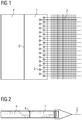
- Fig. 1 shows an example and schematically a rail vehicle assembly with a woven connection between a metallic area 1 and an area made of fiber-plastic composite 2 in a plan view.
- a section of a rail vehicle assembly is shown at its edge, which comprises a metallic area 1 and an area made of fiber-plastic composite 2.
- the area made of fiber-plastic composite 2 forms the main component of the rail vehicle assembly and is connected to a metallic area 1 for mounting on further assemblies of a rail vehicle, which typically includes the area made of fiber-plastic composite 2 along its circumference.
- the connection of the area made of fiber-plastic composite 2 with the metallic area 1 takes place in the exemplary embodiment shown by means of interweaving, ie fibers of the area made of fiber-plastic composite 2 through recesses 3 of the metallic area 1.
- Fig. 2 shows by way of example and schematically a rail vehicle assembly not according to the invention with a woven connection between a metallic area 1 and an area made of fiber-plastic composite 2 in a sectional illustration. It is the embodiment from Fig. 1 shown in a section, whereby the weave structure, ie the passage of fibers of the area of fiber-plastic composite 2 through recesses 3 of the metallic area is clearly visible.
- Fig. 3 shows by way of example and schematically a rail vehicle assembly not according to the invention with a wrapped connection between a metallic area 1 and an area made of fiber-plastic composite 2 in a plan view. It is similar to the one in Fig. 1
- the illustrated embodiment shows a positive connection by passing fibers of the area made of fiber-plastic composite 2 through recesses 3 of the metallic area 1, but the recesses 3 as rounded notches on a side of the metallic area 1 facing away from the area made of fiber-plastic composite 2 are executed. This type of execution simplifies the connection as there is no need to drill a large number of holes.
- the weld seam 6 for connection to a further assembly 4 is, however, to be interrupted.
- Fig. 4 shows, by way of example and schematically, a rail vehicle assembly with a lined connection between a metallic area 1 and an area made of fiber-plastic composite 2 in a sectional illustration.
- the area made of fiber-plastic composite 2 is provided at its edge with a hem 5, which results in a local doubling of the thickness.
- This seam 5 is clamped in a recess in the metallic area 1 and is thus connected to it in a form-fitting manner.
- the metallic area 1 is made in two parts and is closed by means of a weld 6 after the insertion of the seam 5.
- the weld seam 6 also forms the connection to a further assembly 4, so that both the two-part metallic area 1 can be closed and the connection to a further assembly 4 can be established with a single welding process.
- the two-part metallic area 1 can also first be closed by means of the weld 6 and then the rail vehicle assembly can be connected to a further assembly 4.
- Fig. 5 shows, by way of example and schematically, a rail vehicle assembly with a connection between a metallic area 1 and an area made of fiber-plastic composite 2, which is lined around a reinforcing rod, in a sectional illustration. It's one of the in Fig. 4 shown embodiment very similar Embodiment shown, wherein the seam 5 is formed around a reinforcing rod. In this way, the increase in thickness in the area of the seam 5 is much more pronounced and the form fit between the metallic area 1 and the area made of fiber-plastic composite 2 is significantly improved.
- Fig. 6 shows an example and schematic of a rail vehicle assembly from a multi-layered area made of fiber-plastic composite 2 in a sectional illustration.
- An area consisting of an area made of fiber-plastic composite 2 is surrounded on both sides by a metallic area 1 each (planked with a cover layer) and has a metallic core layer. These three layers are brought together at the edge of the area made of fiber-plastic composite 2 and together form a metallic area for producing a weld 6 to form a further assembly.
- This embodiment is particularly advantageous when using prefabricated sandwich panels made of metal and fiber-plastic composite, in which no addition of resin is required.
Landscapes
- Engineering & Computer Science (AREA)
- Mechanical Engineering (AREA)
- Chemical & Material Sciences (AREA)
- Composite Materials (AREA)
- Body Structure For Vehicles (AREA)
Description
- Die Erfindung betrifft eine Schienenfahrzeugbaugruppe, insbesondere eine solche aus Faser-Kunststoff Verbund.
- Die Tragstrukturen von Schienenfahrzeugen werden üblicherweise aus Metall gefertigt, wodurch zwar auf bewährte Fertigungs- und Verbindungstechnologien zurückgegriffen werden kann, jedoch gegenüber Kunststoffen ein höheres Gewicht der Fahrzeuge die Folge ist. Kunststoffe werden praktisch ausschließlich für Innenraumverkleidungen von Passagierräumen und als formbestimmende Designbauteile an der Stirnseite angewandt. Während bei anderen Transportmitteln wie Flugzeugen oder Kraftfahrzeugen der Einsatz von Kunststoffen, insbesondere Faser-Kunststoff Verbund Materialien (glasfaserverstärkter Kunststoff GfK) gebräuchlich ist, so werden diese leichten Materialien bei Schienenfahrzeugen vor allem wegen fehlender oder ungenügender Fügetechnik zwischen dem Kunststoffteilen, z.B. einer Seitenwand und metallischen Baugruppen, z.B. einem Untergestell nur selten angewandt. Prinzipiell können große Baugruppen wie Seitenwände, Stirnseiten oder Dach eines Schienenfahrzeugs untereinander und mit metallischen Baugruppen durch verschiedene Fügetechniken verbunden werden. Beispielsweise kann diese Verbindung mittels Kleben, Schrauben oder Nieten gefügt werden. Die wegen ihrer guten Automatisierbarkeit bevorzugt angewandte Schweißtechnologie ist bei Kunststoff- Metallverbindungen naturgemäß nicht einsetzbar. Solcherart ist für die manuelle Herstellung der Verbindung mit einem wesentlich höheren Aufwand zu rechnen. Es sind aus dem Stand der Technik keine Möglichkeiten bekannt, wie eine Verbindung zwischen einer Kunststoffbaugruppe und einer metallischen Baugruppe einfach und schnell schweißbar gestaltet werden kann
EP 1 048 442 A1 offenbart eine Fahrzeugbaugruppe umfassend einen Bereich aus Faser-Kunststoff Verbund und einen metallischen Bereich, wobei der metallische Bereich mit dem Bereich aus Faser-Kunststoff Verbund unter Formschluß verbunden ist. - Der Erfindung liegt daher die Aufgabe zugrunde, eine Schienenfahrzeugbaugruppe anzugeben, welche im Wesentlichen aus einem Faser-Kunststoff Verbund besteht und welche zur Herstellung einer Schweißverbindung mit weiteren Baugruppen ausgebildet ist.
- Die Aufgabe wird durch eine Schienenfahrzeugbaugruppe mit den Merkmalen des Anspruchs 1 gelöst. Vorteilhafte Ausgestaltungen sind Gegenstand untergeordneter Ansprüche.
- Dem Grundgedanken der Erfindung nach wird eine Schienenfahrzeugbaugruppe, umfassend mindestens einen Bereich aus Faser-Kunststoff Verbund und mindestens einen metallischen Bereich beschrieben, wobei der metallische Bereich mit dem Bereich aus Faser-Kunststoff Verbund unter Formschluß verbunden ist.
- Dadurch ist der Vorteil erzielbar, eine Schienenfahrzeugbaugruppe aufbauen zu können, welche die Vorteile von Faser-Kunststoff Verbund aufweist, dabei zur Verbindung mit weiteren Baugruppen jedoch metallische Bereiche aufweist, mittels welchen eine Schweißverbindung zu diesen weiteren Baugruppen herstellbar ist.
- Erfindungsgemäß wird eine Baugruppe, beispielsweise eine Seitenwand, eine Stirnwand oder ein Dach aus Faser-Kunststoff Verbund aufgebaut, wodurch die spezifischen Vorteile dieser Konstruktion, insbesondere das geringe Gewicht erzielt werden. Als Faser-Kunststoff Verbund sind alle Faser-Harz Kombinationen einsetzbar die die Herstellung von Baugruppen mit den bei Schienenfahrzeugen üblichen Anforderungen geeignet sind. Als Fasermaterial ist Glasfaser, Kohlefaser oder Aramidfaser einsetzbar. Diese Fasern werden zu Geweben verbunden und weisen gerichtete Fasern auf. Strukturen aus ungerichteten Fasern, sogenannte Vliese bzw. "nonwovens" sind für diese Anwendung nicht geeignet. Als Harze können insbesondere Polyesterharze, Epoxidharze und Phenolharze eingesetzt werden.
- Mindestens ein metallischer Bereich grenzt an den Bereich aus Faser-Kunststoff Verbund an und ist mit diesem formschlüssig verbunden.
- Erfindungsgemäß ist der Bereich aus Faser-Kunststoff Verbund an seiner dem metallischen Bereich zugewandten Berandung mit einem Saum zu versehen und dabei zu vernähen. Die durch den Saum entstehende Verdopplung der Dicke des Bereichs aus Faser-Kunststoff Verbund wird formschlüssig in dem metallischen Bereich geklemmt gehalten. Der Saum kann einfach oder mehrfach ausgeführt sein, wobei sich jeweils eine Verdoppelung der Dicke erzielen läßt. Der metallische Bereich ist zur Aufnahme und Klemmung des Saums mit einer Ausnehmung auszustatten, wobei der metallische Bereich zweiteilig aufgebaut sein kann und zur Klemmung des Saums die beiden Teile unlösbar miteinander verbunden werden.
- Eine bevorzugte Ausführung der Erfindung sieht vor, den Saum um eine Verstärkungsstange herum zu bilden. Dabei wird ein stangenförmiges Material, vorzugsweise ein metallischer Rundstab von dem Saum umschlossen, wodurch eine wesentlich verbesserte Kraftübertragung zwischen dem metallischen Bereich und dem Bereich aus Faser-Kunststoff Verbund gewährleistet ist.
- Zur Herstellung einer erfindungsgemäßen Baugruppe ist in einem ersten Schritt die Grundstruktur der Baugruppe aus dem Faser-Kunststoff Verbund aufzubauen, d.h. in einer geeigneten Form aufzulegen. In einem zweiten Schritt ist der Bereich aus Faser-Kunststoff Verbund nach einer der dargelegten Methoden formschlüssig zu verbinden. In einem dritten Schritt ist das Gewebe des Bereichs aus Faser-Kunststoff Verbund mit Harz zu füllen.
- Es zeigen beispielhaft:
-
Fig.1 Schienenfahrzeugbaugruppe, Verbindung gewoben, Aufsicht. -
Fig.2 Nicht erfindungsgemäße Schienenfahrzeugbaugruppe, Verbindung gewoben, Schnitt. -
Fig.3 Nicht erfindungsgemäße Schienenfahrzeugbaugruppe, Verbindung umwickelt, Aufsicht. -
Fig.4 Schienenfahrzeugbaugruppe, Verbindung gesäumt, Schnitt. -
Fig.4 Schienenfahrzeugbaugruppe, Verbindung gesäumt mit Verstärkungsstange, Schnitt. -
Fig.6 Schienenfahrzeugbaugruppe, Mehrschicht, Schnitt. -
Fig.1 zeigt beispielhaft und schematisch eine Schienenfahrzeugbaugruppe mit einer gewobenen Verbindung zwischen einem metallischen Bereich 1 und einem Bereich aus Faser-Kunststoff Verbund 2 in einer Aufsicht. Es ist ein Ausschnitt einer Schienenfahrzeugbaugruppe an ihrem Rand dargestellt, welche einen metallischen Bereich 1 und einen Bereich aus Faser-Kunststoff Verbund 2 umfasst. Der Bereich aus Faser-Kunststoff Verbund 2 bildet Hauptkomponente der Schienenfahrzeugbaugruppe und ist zur Montage an weiteren Baugruppen eines Schienenfahrzeugs mit einem metallischen Bereich 1 verbunden, welcher typischerweise den Bereich aus Faser-Kunststoff Verbund 2 entlang seines Umfangs umfasst. Die Verbindung des Bereichs aus Faser-Kunststoff Verbund 2 mit dem metallischen Bereich 1 erfolgt in gezeigtem Ausführungsbeispiel mittels verweben, d.h. durchführen von Fasern des Bereichs aus Faser-Kunststoff Verbund 2 durch Ausnehmungen 3 des metallischen Bereichs 1. Diese durch die Ausnehmungen 3 geführten Fasern sind wieder zurück in den Bereich aus Faser-Kunststoff Verbund 2 geführt und mit Harz verbunden. Solcherart entsteht eine formschlüssige Verbindung der Bereiche 1, 2, welche durch das Versehen des Fasermaterials mit Harz gefestigt wird. Dabei kann die hohe Zugfestigkeit der Fasern genutzt werden und die Abhängigkeit von der Festigkeit einer sonst erforderlichen Klebestelle entfällt. Zur weiteren Erläuterung der Funktion der Schienenfahrzeugbaugruppe ist eine Verbindung mit einer weiteren Baugruppe 4 gezeigt, welche mittels einer Schweißnaht 6 mit dem metallischen Bereich 1 der Schienenfahrzeugbaugruppe verbunden ist. Die Abmessungen des metallischen Bereichs 1 sind so gestaltet, dass die Hitzeeinwirkungen des Schweißvorgangs den harzgebundenen Bereich aus Faser-Kunststoff Verbund 2 nicht beeinflussen. -
Fig.2 zeigt beispielhaft und schematisch eine nicht erfindungsgemäße Schienenfahrzeugbaugruppe mit einer gewobenen Verbindung zwischen einem metallischen Bereich 1 und einem Bereich aus Faser-Kunststoff Verbund 2 in einer Schnittdarstellung. Es ist das Ausführungsbeispiel ausFig.1 in einem Schnitt dargestellt, wodurch die Webstruktur, d.h. das Durchführen von Fasern des Bereichs aus Faser-Kunststoff Verbund 2 durch Ausnehmungen 3 des metallischen Bereichs gut erkenntlich ist. -
Fig.3 zeigt beispielhaft und schematisch eine nicht erfindungsgemäße Schienenfahrzeugbaugruppe mit einer umwickelten Verbindung zwischen einem metallischen Bereich 1 und einem Bereich aus Faser-Kunststoff Verbund 2 in einer Aufsicht. Es ist, ähnlich wie in dem inFig.1 dargestellten Ausführungsbeispiel eine formschlüssige Verbindung durch durchführen von Fasern des Bereichs aus Faser-Kunststoff Verbund 2 durch Ausnehmungen 3 des metallischen Bereichs 1 gezeigt, wobei jedoch die Ausnehmungen 3 als verrundete Einkerbungen auf einer dem Bereich aus Faser-Kunststoff Verbund 2 abgewandten Seite des metallischen Bereichs 1 ausgeführt sind. Diese Ausführungsart vereinfacht die Verbindung, da keine Vielzahl an Bohrungen herzustellen ist. Die Schweißnaht 6 zur Verbindung mit einer weiteren Baugruppe 4 ist dabei jedoch unterbrochen auszuführen. -
Fig.4 zeigt beispielhaft und schematisch eine Schienenfahrzeugbaugruppe mit einer gesäumten Verbindung zwischen einem metallischen Bereich 1 und einem Bereich aus Faser-Kunststoff Verbund 2 in einer Schnittdarstellung. Bei dieser Ausführungsart ist der Bereich aus Faser-Kunststoff Verbund 2 an seinem Rand mit einem Saum 5 versehen, wodurch sich eine lokale Verdoppelung der Dicke ergibt. Dieser Saum 5 ist in einer Ausnehmung des metallischen Bereichs 1 geklemmt und somit formschlüssig mit diesem verbunden. Der metallische Bereich 1 ist zweiteilig ausgeführt und wird nach dem Einlegen des Saums 5 mittels einer Schweißnaht 6 verschlossen. Die Schweißnaht 6 bildet dabei auch die Verbindung zu einer weiteren Baugruppe 4, sodass mit einem einzigen Schweißvorgang sowohl der zweiteilige metallische Bereich 1 geschlossen werden kann und die Verbindung zu einer weiteren Baugruppe 4 hergestellt werden kann. Alternativ dazu kann mittels der Schweißnaht 6 auch zuerst der zweiteilige metallische Bereich 1 geschlossen werden und in weiterer Folge die Schienenfahrzeugbaugruppe mit einer weiteren Baugruppe 4 verbunden werden. -
Fig.5 zeigt beispielhaft und schematisch eine Schienenfahrzeugbaugruppe mit einer um eine Verstärkungsstange gesäumten Verbindung zwischen einem metallischen Bereich 1 und einem Bereich aus Faser-Kunststoff Verbund 2 in einer Schnittdarstellung. Es ist ein dem inFig.4 gezeigten Ausführungsbeispiel sehr ähnliches Ausführungsbeispiel dargestellt, wobei der Saum 5 um eine Verstärkungsstange herum gebildet ist. Solcherart ist die Dickenerhöhung im Bereich des Saums 5 wesentlich ausgeprägter und der Formschluß zwischen dem metallischen Bereich 1 und dem Bereich aus Faser-Kunststoff Verbund 2 ist wesentlich verbessert. -
Fig.6 zeigt beispielhaft und schematisch Schienenfahrzeugbaugruppe aus einem mehrschichtig aufgebauten Bereich aus Faser-Kunststoff Verbund 2 in einer Schnittdarstellung. Es ist ein Bereich aus Bereich aus Faser-Kunststoff Verbund 2 beidseitig von je einem metallischen Bereich 1 umgeben (mit einer Decklage beplankt) und weist eine metallische Kernlage auf. Diese drei Lagen sind an der Berandung des Bereichs aus Faser-Kunststoff Verbund 2 zusammengeführt und bilden gemeinsam einen metallischen Bereich zur Herstellung einer Schweißnaht 6 zu einer weiteren Baugruppe. Diese Ausführungsform ist insbesondere bei der Anwendung vorgefertigter Sandwichplatten aus Metall und Faser-Kunststoff Verbund vorteilhaft, bei welchem kein zufügen von Harz erforderlich ist. -
- 1
- Metallischer Bereich
- 2
- Faser-Kunststoff Verbund
- 3
- Ausnehmung
- 4
- Weitere Baugruppe
- 5
- Saum
- 6
- Schweißnaht
- 7
- Verstärkungsstange
Claims (6)
- Schienenfahrzeugbaugruppe, umfassend mindestens einen Bereich aus Faser-Kunststoff Verbund (2) und mindestens einen metallischen Bereich (1),
dadurch gekennzeichnet, dass
der metallische Bereich (1) mit dem Bereich aus Faser-Kunststoff Verbund (2) unter Formschluß verbunden ist, wobei
der Bereich aus Faser-Kunststoff Verbund (2) an seinem Rand mit einem Saum (5) ausgeführt ist und dieser Saum (5) unter Formschluß mit dem metallischen Bereich (1) verbunden ist. - Schienenfahrzeugbaugruppe nach Anspruch 1,
dadurch gekennzeichnet, dass der Saum (5) um eine Verstärkungsstange (7) herum gebildet ist. - Schienenfahrzeugbaugruppe nach einem der Ansprüche 1 oder 2 dadurch gekennzeichnet, dass der metallische Bereich (1) den Umfang des Bereichs aus Faser-Kunststoff Verbund (2) allseitig umfasst.
- Schienenfahrzeugbaugruppe nach einem der Ansprüche 1 bis 3 dadurch gekennzeichnet, dass der metallische Bereich (1) zur Herstellung einer Schweißverbindung mit einem weiteren Bauteil (4) ausgebildet ist.
- Schienenfahrzeugbaugruppe nach einem der Ansprüche 1 bis 4 dadurch gekennzeichnet, dass die Schienenfahrzeugbaugruppe eine Seitenwand oder eine Stirnwand oder ein Dach eines Schienenfahrzeugs ist.
- Schienenfahrzeug, umfassend mindestens eine Baugruppe nach einem der Ansprüche 1 bis 5.
Priority Applications (1)
| Application Number | Priority Date | Filing Date | Title |
|---|---|---|---|
| PL16781740T PL3344509T3 (pl) | 2015-10-14 | 2016-10-11 | Zespół pojazdu szynowego |
Applications Claiming Priority (2)
| Application Number | Priority Date | Filing Date | Title |
|---|---|---|---|
| ATA50874/2015A AT517825B1 (de) | 2015-10-14 | 2015-10-14 | Schienenfahrzeugbaugruppe |
| PCT/EP2016/074310 WO2017064045A1 (de) | 2015-10-14 | 2016-10-11 | Schienenfahrzeugbaugruppe |
Publications (2)
| Publication Number | Publication Date |
|---|---|
| EP3344509A1 EP3344509A1 (de) | 2018-07-11 |
| EP3344509B1 true EP3344509B1 (de) | 2021-03-10 |
Family
ID=57136863
Family Applications (1)
| Application Number | Title | Priority Date | Filing Date |
|---|---|---|---|
| EP16781740.2A Active EP3344509B1 (de) | 2015-10-14 | 2016-10-11 | Schienenfahrzeugbaugruppe |
Country Status (4)
| Country | Link |
|---|---|
| EP (1) | EP3344509B1 (de) |
| AT (1) | AT517825B1 (de) |
| PL (1) | PL3344509T3 (de) |
| WO (1) | WO2017064045A1 (de) |
Family Cites Families (8)
| Publication number | Priority date | Publication date | Assignee | Title |
|---|---|---|---|---|
| GB8528966D0 (en) * | 1985-11-25 | 1986-01-02 | Raychem Ltd | Wrap-around fabric articles |
| AT389500B (de) * | 1987-01-08 | 1989-12-11 | Fuchs Herbert | Bootskoerper |
| DE8709691U1 (de) * | 1987-07-14 | 1987-11-26 | Schmitz-Anhaenger Fahrzeugbau Gesellschaft Mbh & Co, 4417 Altenberge, De | |
| ES2208248T3 (es) * | 1999-03-31 | 2004-06-16 | ALCAN TECHNOLOGY & MANAGEMENT AG | Componente de plastico con partes de insercion. |
| DE102010054097A1 (de) * | 2010-12-10 | 2012-06-14 | Audi Ag | Verfahren zur Herstellung eines Metall-Faserverbund-Bauteiles |
| DE102012010424B4 (de) * | 2012-05-23 | 2014-02-13 | Technische Universität Dresden | Verfahren zur Herstellung eines Verbundbauteils und ein mit dem Verfahren hergestelltes Verbundbauteil |
| DE102013200677A1 (de) * | 2013-01-17 | 2014-07-17 | Bayerische Motoren Werke Aktiengesellschaft | Karosseriestrukturelement und Verfahren zum Herstellen eines Karosseriestrukturelements |
| DE102013207982A1 (de) * | 2013-04-30 | 2014-10-30 | Bayerische Motoren Werke Aktiengesellschaft | Hybridbauteil für ein Kraftfahrzeug |
-
2015
- 2015-10-14 AT ATA50874/2015A patent/AT517825B1/de not_active IP Right Cessation
-
2016
- 2016-10-11 WO PCT/EP2016/074310 patent/WO2017064045A1/de active Application Filing
- 2016-10-11 EP EP16781740.2A patent/EP3344509B1/de active Active
- 2016-10-11 PL PL16781740T patent/PL3344509T3/pl unknown
Non-Patent Citations (1)
| Title |
|---|
| None * |
Also Published As
| Publication number | Publication date |
|---|---|
| EP3344509A1 (de) | 2018-07-11 |
| AT517825A1 (de) | 2017-04-15 |
| PL3344509T3 (pl) | 2021-09-27 |
| WO2017064045A1 (de) | 2017-04-20 |
| AT517825B1 (de) | 2017-11-15 |
Similar Documents
| Publication | Publication Date | Title |
|---|---|---|
| EP2509772B1 (de) | Verfahren zum anbinden eines faserverbundbauteils an ein strukturbauteil eines luft- und raumfahrzeuges und eine entsprechende anordnung | |
| EP3041668B1 (de) | Composite-bauteil für einen fahrzeugsitz sowie fahrzeugsitz | |
| DE102014009446B4 (de) | Duroplastische FVK-Struktur mit einem thermoplastischen und faserverstärkten Lasteinleitungselement | |
| DE202014100399U1 (de) | Verbundwerkstoffgegenstände mit einem reduzierten Fasergehalt in lokalen Bereichen | |
| DE102010042128A1 (de) | Strukturbauteil, Luft- oder Raumfahrzeug sowie Verfahren | |
| DE102011120636A1 (de) | Faserverbundbauteilanordnung mit mindestens zwei plattenförmigen Faserverbundbauteilen sowie Verfahren zur Herstellung derselben | |
| EP2774732B1 (de) | "Führungsschiene mit einer CFK-Einlage" | |
| DE102010003356B4 (de) | Verfahren zur Herstellung eines Bauteils aus einem Verbundmaterial und Komponente für ein Bauteil aus einem Verbundmaterial | |
| DE10326422A1 (de) | Verfahren zur Herstellung von sich in einer Längsrichtung erstreckenden FVK-Hohlprofilen | |
| EP3489000A1 (de) | Verfahren zum herstellen eines faserverbundbauteils | |
| DE102004010768B4 (de) | Blattfeder für eine Radaufhängung an einem Fahrzeug | |
| DE102013221172A1 (de) | Verfahren zum Herstellen eines verstärkten Faserverbundbauteils | |
| DE102010030550B4 (de) | Verbundbauteil mit einem Gewebe mit integrierten Profilen | |
| DE102013222356A1 (de) | Verfahren zum Herstellen eines integralen Faserverbundbauteils mit Einlegeelement | |
| DE102012211765A1 (de) | Kernschicht für ein Sandwichverbundbauteil, Sandwichverbundbauteil und Verfahren zur Herstellung eines Sandwichverbundbauteils | |
| EP2998591A1 (de) | Verbindungselement | |
| DE102011116300B4 (de) | Faserverbundwerkstoff-Bauteil mit metallischem Anschlussstück und damit gefertigtes Verbundbauteil | |
| EP3344509B1 (de) | Schienenfahrzeugbaugruppe | |
| DE102014019080A1 (de) | Verfahren zur Herstellung eines faserverstärkten Strukturbauteils | |
| EP2280821B1 (de) | Ausschnittsverstärkung für kernverbunde und verfahren zu deren herstellung | |
| DE102012001055B4 (de) | Bauteil | |
| DE102011107512B4 (de) | Duktile CFK-Struktur | |
| DE102013205440A1 (de) | Verfahren zur Herstellung eines Faserverbundbauteils mit verstärktem Anbindungsabschnitt zur lokalen Krafteinleitung | |
| DE102013204953A1 (de) | Baugruppe einer Kraftfahrzeugkarosserie | |
| DE102019206217A1 (de) | Fahrwerklenker |
Legal Events
| Date | Code | Title | Description |
|---|---|---|---|
| STAA | Information on the status of an ep patent application or granted ep patent |
Free format text: STATUS: THE INTERNATIONAL PUBLICATION HAS BEEN MADE |
|
| PUAI | Public reference made under article 153(3) epc to a published international application that has entered the european phase |
Free format text: ORIGINAL CODE: 0009012 |
|
| STAA | Information on the status of an ep patent application or granted ep patent |
Free format text: STATUS: REQUEST FOR EXAMINATION WAS MADE |
|
| 17P | Request for examination filed |
Effective date: 20180405 |
|
| AK | Designated contracting states |
Kind code of ref document: A1 Designated state(s): AL AT BE BG CH CY CZ DE DK EE ES FI FR GB GR HR HU IE IS IT LI LT LU LV MC MK MT NL NO PL PT RO RS SE SI SK SM TR |
|
| AX | Request for extension of the european patent |
Extension state: BA ME |
|
| DAV | Request for validation of the european patent (deleted) | ||
| DAX | Request for extension of the european patent (deleted) | ||
| RAP1 | Party data changed (applicant data changed or rights of an application transferred) |
Owner name: SIEMENS MOBILITY GMBH |
|
| RAP1 | Party data changed (applicant data changed or rights of an application transferred) |
Owner name: SIEMENS MOBILITY AUSTRIA GMBH |
|
| GRAP | Despatch of communication of intention to grant a patent |
Free format text: ORIGINAL CODE: EPIDOSNIGR1 |
|
| STAA | Information on the status of an ep patent application or granted ep patent |
Free format text: STATUS: GRANT OF PATENT IS INTENDED |
|
| INTG | Intention to grant announced |
Effective date: 20201023 |
|
| GRAS | Grant fee paid |
Free format text: ORIGINAL CODE: EPIDOSNIGR3 |
|
| STAA | Information on the status of an ep patent application or granted ep patent |
Free format text: STATUS: GRANT OF PATENT IS INTENDED |
|
| GRAA | (expected) grant |
Free format text: ORIGINAL CODE: 0009210 |
|
| STAA | Information on the status of an ep patent application or granted ep patent |
Free format text: STATUS: THE PATENT HAS BEEN GRANTED |
|
| AK | Designated contracting states |
Kind code of ref document: B1 Designated state(s): AL AT BE BG CH CY CZ DE DK EE ES FI FR GB GR HR HU IE IS IT LI LT LU LV MC MK MT NL NO PL PT RO RS SE SI SK SM TR |
|
| REG | Reference to a national code |
Ref country code: GB Ref legal event code: FG4D Free format text: NOT ENGLISH |
|
| REG | Reference to a national code |
Ref country code: AT Ref legal event code: REF Ref document number: 1369522 Country of ref document: AT Kind code of ref document: T Effective date: 20210315 Ref country code: CH Ref legal event code: EP |
|
| REG | Reference to a national code |
Ref country code: DE Ref legal event code: R096 Ref document number: 502016012575 Country of ref document: DE |
|
| REG | Reference to a national code |
Ref country code: IE Ref legal event code: FG4D Free format text: LANGUAGE OF EP DOCUMENT: GERMAN |
|
| REG | Reference to a national code |
Ref country code: LT Ref legal event code: MG9D |
|
| PG25 | Lapsed in a contracting state [announced via postgrant information from national office to epo] |
Ref country code: BG Free format text: LAPSE BECAUSE OF FAILURE TO SUBMIT A TRANSLATION OF THE DESCRIPTION OR TO PAY THE FEE WITHIN THE PRESCRIBED TIME-LIMIT Effective date: 20210610 Ref country code: LT Free format text: LAPSE BECAUSE OF FAILURE TO SUBMIT A TRANSLATION OF THE DESCRIPTION OR TO PAY THE FEE WITHIN THE PRESCRIBED TIME-LIMIT Effective date: 20210310 Ref country code: NO Free format text: LAPSE BECAUSE OF FAILURE TO SUBMIT A TRANSLATION OF THE DESCRIPTION OR TO PAY THE FEE WITHIN THE PRESCRIBED TIME-LIMIT Effective date: 20210610 Ref country code: FI Free format text: LAPSE BECAUSE OF FAILURE TO SUBMIT A TRANSLATION OF THE DESCRIPTION OR TO PAY THE FEE WITHIN THE PRESCRIBED TIME-LIMIT Effective date: 20210310 Ref country code: HR Free format text: LAPSE BECAUSE OF FAILURE TO SUBMIT A TRANSLATION OF THE DESCRIPTION OR TO PAY THE FEE WITHIN THE PRESCRIBED TIME-LIMIT Effective date: 20210310 Ref country code: GR Free format text: LAPSE BECAUSE OF FAILURE TO SUBMIT A TRANSLATION OF THE DESCRIPTION OR TO PAY THE FEE WITHIN THE PRESCRIBED TIME-LIMIT Effective date: 20210611 |
|
| REG | Reference to a national code |
Ref country code: NL Ref legal event code: MP Effective date: 20210310 |
|
| PG25 | Lapsed in a contracting state [announced via postgrant information from national office to epo] |
Ref country code: SE Free format text: LAPSE BECAUSE OF FAILURE TO SUBMIT A TRANSLATION OF THE DESCRIPTION OR TO PAY THE FEE WITHIN THE PRESCRIBED TIME-LIMIT Effective date: 20210310 Ref country code: RS Free format text: LAPSE BECAUSE OF FAILURE TO SUBMIT A TRANSLATION OF THE DESCRIPTION OR TO PAY THE FEE WITHIN THE PRESCRIBED TIME-LIMIT Effective date: 20210310 Ref country code: LV Free format text: LAPSE BECAUSE OF FAILURE TO SUBMIT A TRANSLATION OF THE DESCRIPTION OR TO PAY THE FEE WITHIN THE PRESCRIBED TIME-LIMIT Effective date: 20210310 |
|
| PG25 | Lapsed in a contracting state [announced via postgrant information from national office to epo] |
Ref country code: NL Free format text: LAPSE BECAUSE OF FAILURE TO SUBMIT A TRANSLATION OF THE DESCRIPTION OR TO PAY THE FEE WITHIN THE PRESCRIBED TIME-LIMIT Effective date: 20210310 |
|
| PG25 | Lapsed in a contracting state [announced via postgrant information from national office to epo] |
Ref country code: EE Free format text: LAPSE BECAUSE OF FAILURE TO SUBMIT A TRANSLATION OF THE DESCRIPTION OR TO PAY THE FEE WITHIN THE PRESCRIBED TIME-LIMIT Effective date: 20210310 Ref country code: CZ Free format text: LAPSE BECAUSE OF FAILURE TO SUBMIT A TRANSLATION OF THE DESCRIPTION OR TO PAY THE FEE WITHIN THE PRESCRIBED TIME-LIMIT Effective date: 20210310 Ref country code: SM Free format text: LAPSE BECAUSE OF FAILURE TO SUBMIT A TRANSLATION OF THE DESCRIPTION OR TO PAY THE FEE WITHIN THE PRESCRIBED TIME-LIMIT Effective date: 20210310 |
|
| PG25 | Lapsed in a contracting state [announced via postgrant information from national office to epo] |
Ref country code: IS Free format text: LAPSE BECAUSE OF FAILURE TO SUBMIT A TRANSLATION OF THE DESCRIPTION OR TO PAY THE FEE WITHIN THE PRESCRIBED TIME-LIMIT Effective date: 20210710 Ref country code: PT Free format text: LAPSE BECAUSE OF FAILURE TO SUBMIT A TRANSLATION OF THE DESCRIPTION OR TO PAY THE FEE WITHIN THE PRESCRIBED TIME-LIMIT Effective date: 20210712 Ref country code: RO Free format text: LAPSE BECAUSE OF FAILURE TO SUBMIT A TRANSLATION OF THE DESCRIPTION OR TO PAY THE FEE WITHIN THE PRESCRIBED TIME-LIMIT Effective date: 20210310 Ref country code: SK Free format text: LAPSE BECAUSE OF FAILURE TO SUBMIT A TRANSLATION OF THE DESCRIPTION OR TO PAY THE FEE WITHIN THE PRESCRIBED TIME-LIMIT Effective date: 20210310 |
|
| REG | Reference to a national code |
Ref country code: DE Ref legal event code: R097 Ref document number: 502016012575 Country of ref document: DE |
|
| PLBE | No opposition filed within time limit |
Free format text: ORIGINAL CODE: 0009261 |
|
| STAA | Information on the status of an ep patent application or granted ep patent |
Free format text: STATUS: NO OPPOSITION FILED WITHIN TIME LIMIT |
|
| PG25 | Lapsed in a contracting state [announced via postgrant information from national office to epo] |
Ref country code: DK Free format text: LAPSE BECAUSE OF FAILURE TO SUBMIT A TRANSLATION OF THE DESCRIPTION OR TO PAY THE FEE WITHIN THE PRESCRIBED TIME-LIMIT Effective date: 20210310 Ref country code: ES Free format text: LAPSE BECAUSE OF FAILURE TO SUBMIT A TRANSLATION OF THE DESCRIPTION OR TO PAY THE FEE WITHIN THE PRESCRIBED TIME-LIMIT Effective date: 20210310 Ref country code: AL Free format text: LAPSE BECAUSE OF FAILURE TO SUBMIT A TRANSLATION OF THE DESCRIPTION OR TO PAY THE FEE WITHIN THE PRESCRIBED TIME-LIMIT Effective date: 20210310 |
|
| 26N | No opposition filed |
Effective date: 20211213 |
|
| PG25 | Lapsed in a contracting state [announced via postgrant information from national office to epo] |
Ref country code: SI Free format text: LAPSE BECAUSE OF FAILURE TO SUBMIT A TRANSLATION OF THE DESCRIPTION OR TO PAY THE FEE WITHIN THE PRESCRIBED TIME-LIMIT Effective date: 20210310 |
|
| PG25 | Lapsed in a contracting state [announced via postgrant information from national office to epo] |
Ref country code: IT Free format text: LAPSE BECAUSE OF FAILURE TO SUBMIT A TRANSLATION OF THE DESCRIPTION OR TO PAY THE FEE WITHIN THE PRESCRIBED TIME-LIMIT Effective date: 20210310 |
|
| PG25 | Lapsed in a contracting state [announced via postgrant information from national office to epo] |
Ref country code: IS Free format text: LAPSE BECAUSE OF FAILURE TO SUBMIT A TRANSLATION OF THE DESCRIPTION OR TO PAY THE FEE WITHIN THE PRESCRIBED TIME-LIMIT Effective date: 20210710 |
|
| REG | Reference to a national code |
Ref country code: CH Ref legal event code: PL |
|
| REG | Reference to a national code |
Ref country code: BE Ref legal event code: MM Effective date: 20211031 |
|
| GBPC | Gb: european patent ceased through non-payment of renewal fee |
Effective date: 20211011 |
|
| PG25 | Lapsed in a contracting state [announced via postgrant information from national office to epo] |
Ref country code: MC Free format text: LAPSE BECAUSE OF FAILURE TO SUBMIT A TRANSLATION OF THE DESCRIPTION OR TO PAY THE FEE WITHIN THE PRESCRIBED TIME-LIMIT Effective date: 20210310 |
|
| PG25 | Lapsed in a contracting state [announced via postgrant information from national office to epo] |
Ref country code: LU Free format text: LAPSE BECAUSE OF NON-PAYMENT OF DUE FEES Effective date: 20211011 Ref country code: GB Free format text: LAPSE BECAUSE OF NON-PAYMENT OF DUE FEES Effective date: 20211011 Ref country code: BE Free format text: LAPSE BECAUSE OF NON-PAYMENT OF DUE FEES Effective date: 20211031 |
|
| PG25 | Lapsed in a contracting state [announced via postgrant information from national office to epo] |
Ref country code: LI Free format text: LAPSE BECAUSE OF NON-PAYMENT OF DUE FEES Effective date: 20211031 Ref country code: CH Free format text: LAPSE BECAUSE OF NON-PAYMENT OF DUE FEES Effective date: 20211031 |
|
| PG25 | Lapsed in a contracting state [announced via postgrant information from national office to epo] |
Ref country code: IE Free format text: LAPSE BECAUSE OF NON-PAYMENT OF DUE FEES Effective date: 20211011 |
|
| PG25 | Lapsed in a contracting state [announced via postgrant information from national office to epo] |
Ref country code: HU Free format text: LAPSE BECAUSE OF FAILURE TO SUBMIT A TRANSLATION OF THE DESCRIPTION OR TO PAY THE FEE WITHIN THE PRESCRIBED TIME-LIMIT; INVALID AB INITIO Effective date: 20161011 |
|
| PG25 | Lapsed in a contracting state [announced via postgrant information from national office to epo] |
Ref country code: CY Free format text: LAPSE BECAUSE OF FAILURE TO SUBMIT A TRANSLATION OF THE DESCRIPTION OR TO PAY THE FEE WITHIN THE PRESCRIBED TIME-LIMIT Effective date: 20210310 |
|
| PGFP | Annual fee paid to national office [announced via postgrant information from national office to epo] |
Ref country code: PL Payment date: 20230928 Year of fee payment: 8 |
|
| PGFP | Annual fee paid to national office [announced via postgrant information from national office to epo] |
Ref country code: FR Payment date: 20231017 Year of fee payment: 8 Ref country code: DE Payment date: 20231214 Year of fee payment: 8 Ref country code: AT Payment date: 20230911 Year of fee payment: 8 |
|
| PG25 | Lapsed in a contracting state [announced via postgrant information from national office to epo] |
Ref country code: MK Free format text: LAPSE BECAUSE OF FAILURE TO SUBMIT A TRANSLATION OF THE DESCRIPTION OR TO PAY THE FEE WITHIN THE PRESCRIBED TIME-LIMIT Effective date: 20210310 |