EP3343181B1 - Vorrichtung zum messen einer winkelposition - Google Patents
Vorrichtung zum messen einer winkelposition Download PDFInfo
- Publication number
- EP3343181B1 EP3343181B1 EP17206953.6A EP17206953A EP3343181B1 EP 3343181 B1 EP3343181 B1 EP 3343181B1 EP 17206953 A EP17206953 A EP 17206953A EP 3343181 B1 EP3343181 B1 EP 3343181B1
- Authority
- EP
- European Patent Office
- Prior art keywords
- angle
- rotation
- main axis
- permanent magnet
- relative
- Prior art date
- Legal status (The legal status is an assumption and is not a legal conclusion. Google has not performed a legal analysis and makes no representation as to the accuracy of the status listed.)
- Active
Links
Images


Classifications
-
- G—PHYSICS
- G01—MEASURING; TESTING
- G01B—MEASURING LENGTH, THICKNESS OR SIMILAR LINEAR DIMENSIONS; MEASURING ANGLES; MEASURING AREAS; MEASURING IRREGULARITIES OF SURFACES OR CONTOURS
- G01B21/00—Measuring arrangements or details thereof, where the measuring technique is not covered by the other groups of this subclass, unspecified or not relevant
- G01B21/22—Measuring arrangements or details thereof, where the measuring technique is not covered by the other groups of this subclass, unspecified or not relevant for measuring angles or tapers; for testing the alignment of axes
-
- G—PHYSICS
- G01—MEASURING; TESTING
- G01D—MEASURING NOT SPECIALLY ADAPTED FOR A SPECIFIC VARIABLE; ARRANGEMENTS FOR MEASURING TWO OR MORE VARIABLES NOT COVERED IN A SINGLE OTHER SUBCLASS; TARIFF METERING APPARATUS; MEASURING OR TESTING NOT OTHERWISE PROVIDED FOR
- G01D5/00—Mechanical means for transferring the output of a sensing member; Means for converting the output of a sensing member to another variable where the form or nature of the sensing member does not constrain the means for converting; Transducers not specially adapted for a specific variable
- G01D5/12—Mechanical means for transferring the output of a sensing member; Means for converting the output of a sensing member to another variable where the form or nature of the sensing member does not constrain the means for converting; Transducers not specially adapted for a specific variable using electric or magnetic means
- G01D5/14—Mechanical means for transferring the output of a sensing member; Means for converting the output of a sensing member to another variable where the form or nature of the sensing member does not constrain the means for converting; Transducers not specially adapted for a specific variable using electric or magnetic means influencing the magnitude of a current or voltage
- G01D5/142—Mechanical means for transferring the output of a sensing member; Means for converting the output of a sensing member to another variable where the form or nature of the sensing member does not constrain the means for converting; Transducers not specially adapted for a specific variable using electric or magnetic means influencing the magnitude of a current or voltage using Hall-effect devices
- G01D5/145—Mechanical means for transferring the output of a sensing member; Means for converting the output of a sensing member to another variable where the form or nature of the sensing member does not constrain the means for converting; Transducers not specially adapted for a specific variable using electric or magnetic means influencing the magnitude of a current or voltage using Hall-effect devices influenced by the relative movement between the Hall device and magnetic fields
Definitions
- This invention relates to a device for measuring an angular position, in particular a device of the type usable for measuring angles of rotation/oscillation that are not greater than 150°.
- a first known type involves the use of a magnetic sensor which is mounted so that it is axially aligned with the axis of rotation of the body whose angular position is to be measured, and magnetically coupled to a permanent magnet positioned eccentrically relative to the axis of rotation.
- measuring systems for measuring an angular position of a rotating body relative to a fixed body, in which a magnet is mounted in such a way that it rotates together with the rotating body and a Hall effect sensor is mounted on the fixed body in a position spaced from the axis of rotation and near the magnet.
- the magnet has the shape of a complete circular or annular arc, whilst in other cases the magnet has the shape of a circular arc (portion of a ring if viewed axially) that only covers part of the circumference (see documents US 2003/048101 , WO 98/08060 , WO 98/ 55828 , US 6310473 , WO 02/061366 , EP 1291615 and WO 2011/139469 ).
- the magnet is radially polarized (magnetized), whilst in other cases the magnet is diametrally polarized (see in particular documents US 2003/048101 , US 6310473 , WO 2004/046653 and WO 2011/139469 ).
- the Hall effect sensor As regards the position of the Hall effect sensor relative to the magnet, in the prior art it has been positioned both radially at the side of the magnet, that is to say, on a more external or more internal circle, and above the magnet, that is to say, axially aligned.
- the technical purpose which forms the basis of this invention is to provide a device for measuring an angular position which overcomes the above-mentioned disadvantages.
- the technical purpose of this invention is to provide a device for measuring an angular position that allows the obtainment both of a continuous measuring signal, and relatively high sensitivity in the entire measuring range.
- Another technical purpose of this invention is to achieve that at a competitive cost.
- the numeral 1 denotes in its entirety a device for measuring an angular position according to this invention.
- the heart of this invention consists of the fact that the Applicant has been able to verify that, surprisingly, it is possible to obtain an output signal that is continuous and with better resolution than the prior art devices, thanks to the use of a permanent magnet having the shape of a ring (annulus) associated with a linear magnetic sensor positioned eccentrically relative to the axis of rotation, and thanks to a particular combination of the size of the magnet, its polarization and the angle of oscillation of the magnet and sensor relative to one other.
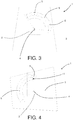
- the measuring device 1 comprises a supporting body 2 and a rotating body 3 that can rotate/oscillate relative to the supporting body 2, about a main axis of rotation 4, between two limit positions ( Figures 4 and 5 ) which are rotated one relative to the other by an angle of oscillation ⁇ with amplitude less than or equal to 150° (during normal operation, then, the rotating body 3 can't oscillate by an angle greater than 150°).
- This invention is even more advantageously applied when the angle of oscillation ⁇ has an amplitude greater than or equal to 90°.
- FIG. 3 to 5 A schematic view of that situation is shown in Figures 3 to 5 , where the main axis of rotation 4 is perpendicular to the sheet and where, for the sole purpose of highlighting the movements relative to one another, the rotating body 3 has been shown with a trapezoidal design and the supporting body 2 with a rectangular design.
- the measuring device 1 also comprises a permanent magnet 5 and a magnetic sensor 6 which are fixed one to the rotating body 3 and the other to the supporting body 2.
- the permanent magnet 5 and the magnetic sensor 6 are also positioned in such a way that the magnetic sensor 6 is magnetically coupled to the permanent magnet 5 in any position relative to one another adopted by the supporting body 2 and by the rotating body 3 during the rotation of the rotating body 3 relative to the supporting body 2.
- the permanent magnet 5 in the plane perpendicular to the main axis of rotation 4, the permanent magnet 5 extends along an arc of extension that corresponds to an arc of a circle centred on the main axis of rotation 4. Consequently, relative to the main axis of rotation 4, the permanent magnet 5 extends through an angle of extension ⁇ that corresponds to the angle at the centre subtended by the arc of extension.
- the magnet is shaped in such a way that, if seen axially (that is to say, parallel to the main axis of rotation 4), it has the shape of a piece of a ring.
- it may advantageously correspond a piece of a toroidal solid, which in the embodiment in Figure 6 for example has a substantially rectangular cross-section (with the exception of small bevels at the edges).
- the permanent magnet 5 has a flat upper face 7 and a flat lower face 8 which are substantially equal and parallel, a curved inner face 9 facing the main axis of rotation 4 and parallel to it, a curved outer face 10 parallel to the curved inner face 9, and two end faces 11 which each lie in their own plane passing through the main axis of rotation 4.
- the angle between those two lying planes of the end faces 11 corresponds to the angle of extension ⁇ of the permanent magnet 5.
- the arc of extension may be identified with the arc that joins the central points (barycentres) of each individual cross-section of the toroidal solid.
- the thickness of the magnet parallel to the main axis of rotation 4 can be set each time based on design requirements.
- the permanent magnet 5 is diametrally polarized (that is to say, always parallel to itself through the whole of the magnet) and has a direction of polarization 12 that forms an angle ⁇ that is less than or equal to 10°, preferably less than 5°, relative to a reference straight line 13 perpendicular to the main axis of rotation 4 and passing both through the main axis of rotation 4, and through a first end of the arc of extension.
- the reference straight line 13 is the radial straight line relative to the axis of rotation, which passes through the central point of one of the end faces 11 (which of the two does not matter, even given the substantial symmetry of the permanent magnet 5).
- the magnetic sensor 6 is positioned eccentrically relative to the main axis of rotation 4 and, preferably, is a Hall effect magnetic sensor 6 able to detect the intensity of the components of magnetic induction along two or three orthogonal detecting axes. It will preferably be positioned in such a way that two of its detecting axes line in a plane perpendicular to the main axis of rotation 4.
- the magnetic sensor 6 is directly facing the permanent magnet 5 at least when the rotating body 3 and the supporting body 2 are positioned relative to one another at a central zone of the angle of oscillation (with a small gap between them, whose size will depend both on the intensity of the magnetic field generated by the permanent magnet 5 and on the sensitivity of the magnetic sensor 6, and will preferably be selected in such a way that the magnetic sensor 6 is immersed in a magnetic field with intensity that the magnetic sensor 6 can perceive).
- the magnetic sensor 6 may be spaced from the permanent magnet 5 alternatively either along a line that is parallel to axis of rotation (as in the accompanying figures, in which it is facing either the flat upper face 7 or the flat lower face 8), which is in accordance with the invention, or along a line that is radial relative to the axis of rotation (and, therefore, alongside the magnet either on the inside - facing the curved inner surface 9 - or on the outside - facing the curved outer surface 10), which is not in accordance with the invention.
- the following relation applies between the angle of extension ⁇ of the permanent magnet 5 and the angle of oscillation ⁇ : ⁇ > ⁇ ⁇ 30 ° preferably also the relation: ⁇ ⁇ ⁇ + 25 ° even more preferably the relation: ⁇ ⁇ ⁇ + 20 ° and yet more preferably the relation: ⁇ ⁇ ⁇ + 10 ° .
- the angle of extension ⁇ of the permanent magnet 5 is less than and the angle of oscillation ⁇ , that is to say, the following relation applies: ⁇ ⁇ ⁇ .
- the permanent magnet 5 and the magnetic sensor 6 are preferably positioned relative to each other in such a way that the stroke of the magnetic sensor 6 relative to the permanent magnet 5 is substantially symmetrical relative to a plane passing through the bisector of the angle of extension ⁇ and through the main axis of rotation 4.
- the magnetic sensor 6 shifts relative to the permanent magnet 5, in the plane that is perpendicular to the main axis of rotation 4, along an arc of oscillation that corresponds to an arc of a circle centred on the main axis of rotation 4 and that subtends an angle at the centre that is equal to the angle of oscillation ⁇ .
- the angle of oscillation ⁇ and the angle of extension ⁇ are arranged with their bisectors coplanar in a half-plane coming out of the main axis of rotation 4.
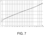
- Figure 7 in particular highlights with a dashed line an example of the output signal obtainable from the magnetic sensor 6 of a measuring device 1 made according to this invention, and in which the angle of oscillation ⁇ is equal to 125°, the angle of extension ⁇ is equal to 115° and in which the direction of polarization 12 corresponds to the above-mentioned reference direction passing through one of the end faces 11 of the permanent magnet 5.
- the unbroken line shows the linearization of the output of the magnetic sensor 6, obtained with the normal calculation and correction techniques adopted in the sector.
- This invention brings important advantages.
- the angle of extension is selected as being less than the angle of oscillation, it is possible to obtain those results at an extremely low cost.
Landscapes
- Physics & Mathematics (AREA)
- General Physics & Mathematics (AREA)
- Transmission And Conversion Of Sensor Element Output (AREA)
Claims (8)
- Eine Vorrichtung zur Messung einer Winkelposition, Folgendes umfassend:einen Stützkörper (2);einen Drehkörper (3), der im Verhältnis zum Stützkörper (2) um eine Hauptrotationsachse (4) schwingen kann, zwischen zwei Grenzpositionen, die im Verhältnis zueinander in einem Schwingwinkel θ gedreht sind, mit einer Amplitude, die kleiner oder gleich 150° ist, und die nicht in einem Winkel größer als 150° schwingen können;einen Dauermagneten (5), der hauptsächlich auf einer Ebene liegt, die lotrecht zur Hauptrotationsachse (4) ist, und sich auf einer Ebene entlang einem Erstreckungsbogen erstreckt, der einem Kreisbogen entspricht, der an der Hauptrotationsachse (4) zentriert ist, und durch einen Erstreckungswinkel α, der dem Mittelpunktswinkel entspricht, zusammengesetzt aus besagtem Kreisbogen, der zwischen den zwei Radien, die die Umfangsmitte mit den Bogenrändern vereinen, gebildet ist, an der Hauptrotationsachse zentriert; undeinen Magnetsensor (6), der exzentrisch in Bezug zur Hauptrotationsachse (4) positioniert ist;der Dauermagnet (5) und der Magnetsensor (6) sind dabei einer am Drehkörper (3) und der andere am Stützkörper (5) befestigt und sie sind dabei solcherart positioniert, dass der Magnetsensor (6) in jeder gegenseitigen Position, die der Stützkörper (2) und der Drehkörper (3) während der Rotation des Drehkörpers (3) im Verhältnis zum Stützkörper (2) zueinander einnehmen, magnetisch an den Dauermagneten (5) gekoppelt ist; wobei:folgende Beziehung zwischen dem Erstreckungswinkel α des Dauermagneten (5) und dem Schwingungswinkel θ besteht:

- Die Vorrichtung nach dem Patentanspruch 1, wobei folgende Beziehung zwischen dem Erstreckungswinkel des Dauermagneten (5) und dem Schwingungswinkel θ besteht:

- Die Vorrichtung nach dem Patentanspruch 1, wobei folgende Beziehung zwischen dem Erstreckungswinkel des Dauermagneten (5) und dem Schwingungswinkel θ besteht:

- Die Vorrichtung nach jedem der vorigen Patentansprüche, wobei folgende Beziehung zwischen dem Erstreckungswinkel des Dauermagneten (5) und dem Schwingungswinkel θ besteht:
- Die Vorrichtung nach jedem der vorigen Patentansprüche, wobei, während der Rotation des Drehkörpers (3) im Verhältnis zum Stützkörper (2), der Magnetsensor (6) sich in Bezug auf den Dauermagneten (5) auf einer Ebene verschiebt, die lotrecht zur Hauptrotationsachse (4) entlang einem Schwingungsbogen ist, der einem Kreisbogen entspricht, der an der Hauptrotationsachse (4) zentriert ist, und einen Mittelpunktswinkel einschließt, der gleich besagtem Schwingungswinkel θ ist; die Mittelpunktswinkel, die den Schwingungswinkel und den Erstreckungswinkel einschließen, sind dabei mit ihren jeweiligen Winkelhalbierenden koplanar auf einer Halbebene, die aus der Hauptrotationsachse (4) kommt, positioniert.
- Die Vorrichtung nach jedem der vorigen Patentansprüche, wobei die Polarisationsrichtung (12) einen Winkel bildet, der kleiner oder gleich 5° ist, im Verhältnis zu besagter gerader Linie, die lotrecht zur Hauptrotationsachse (4) ist und sowohl durch die Hauptrotationsachse (4) als auch durch das erste Ende des Erstreckungswinkels verläuft.
- Die Vorrichtung nach jedem der vorigen Patentansprüche, wobei der Magnetsensor (6) ein Hall-Effekt-Magnetsensor (6) ist und imstande ist, die Intensität der Komponenten der Magnetinduktion entlang zwei oder drei orthogonalen Erfassungsachsen zu erfassen.
- Die Vorrichtung nach jedem der vorigen Patentansprüche, wobei der Drehkörper (3) im Verhältnis zum Stützkörper (2) um die Hauptrotationsachse (4) schwingen kann, zwischen zwei Grenzpositionen, die im Verhältnis zueinander in einem Schwingungswinkel θ mit einer Amplitude größer oder gleich 90° gedreht sind.
Applications Claiming Priority (1)
| Application Number | Priority Date | Filing Date | Title |
|---|---|---|---|
| IT102016000132846A IT201600132846A1 (it) | 2016-12-30 | 2016-12-30 | Dispositivo di misurazione di una posizione angolare |
Publications (2)
| Publication Number | Publication Date |
|---|---|
| EP3343181A1 EP3343181A1 (de) | 2018-07-04 |
| EP3343181B1 true EP3343181B1 (de) | 2020-07-08 |
Family
ID=58701741
Family Applications (1)
| Application Number | Title | Priority Date | Filing Date |
|---|---|---|---|
| EP17206953.6A Active EP3343181B1 (de) | 2016-12-30 | 2017-12-13 | Vorrichtung zum messen einer winkelposition |
Country Status (4)
| Country | Link |
|---|---|
| US (1) | US10422661B2 (de) |
| EP (1) | EP3343181B1 (de) |
| CN (1) | CN108267108B (de) |
| IT (1) | IT201600132846A1 (de) |
Families Citing this family (2)
| Publication number | Priority date | Publication date | Assignee | Title |
|---|---|---|---|---|
| CN109855589B (zh) * | 2019-02-20 | 2023-09-19 | 华电电力科学研究院有限公司 | 利用弦长变化测量汽水管道支吊架吊杆竖直偏角的测量仪及测量方法 |
| CN114166447A (zh) * | 2021-12-23 | 2022-03-11 | 昆山丘钛微电子科技股份有限公司 | 震动测试系统及震动角度监控方法 |
Family Cites Families (20)
| Publication number | Priority date | Publication date | Assignee | Title |
|---|---|---|---|---|
| US4789826A (en) | 1987-03-19 | 1988-12-06 | Ampex Corporation | System for sensing the angular position of a rotatable member using a hall effect transducer |
| FR2715726B1 (fr) | 1994-02-01 | 1996-10-18 | Moving Magnet Tech | Capteur magnétique de position à sonde de Hall. |
| DE19634282A1 (de) | 1996-08-24 | 1998-02-26 | Bosch Gmbh Robert | Meßvorrichtung zur berührungslosen Erfassung eines Drehwinkels |
| FR2764372B1 (fr) | 1997-06-04 | 1999-09-24 | Moving Magnet Tech | Capteur magnetique de position |
| US6310473B1 (en) * | 1998-12-15 | 2001-10-30 | Kearney-National, Inc. | Magnetic rotational position sensor |
| US6448763B1 (en) | 2001-01-10 | 2002-09-10 | Siemens Corporation | System for magnetization to produce linear change in field angle |
| DE10143398A1 (de) | 2001-09-04 | 2003-03-27 | Pierburg Gmbh | Positionssensor |
| US6703829B2 (en) * | 2001-09-07 | 2004-03-09 | Jeff Tola | Magnetic position sensor |
| DE10254552A1 (de) | 2002-11-21 | 2004-06-03 | Siemens Ag | Winkelpositionsgeber |
| DE102006018627A1 (de) | 2006-04-21 | 2007-10-25 | Siemens Ag | Magnetischer Drehwinkelgeber |
| DE102006060808A1 (de) | 2006-12-21 | 2008-06-26 | Siemens Ag | Winkelsensor |
| JP2008267966A (ja) * | 2007-04-19 | 2008-11-06 | Mikuni Corp | マグネットユニット及びアクセルペダル装置 |
| US7570047B2 (en) * | 2007-06-18 | 2009-08-04 | Key Safety Systems, Inc. | Hall effect based angular position sensor |
| CN102472636B (zh) | 2009-07-15 | 2015-06-24 | Skf私人有限公司 | 霍尔效应感应装置 |
| DE102009035091A1 (de) * | 2009-07-28 | 2011-02-10 | Mahle International Gmbh | Positionssensor und Linearaktuator |
| US20110115479A1 (en) * | 2009-11-13 | 2011-05-19 | Blakesley Patrick B | Through Shaft Rotary Position Sensor |
| US9841296B2 (en) * | 2010-05-05 | 2017-12-12 | Continental Automotive Systems, Inc. | Rotary arc position sensor with linear output |
| US9052029B2 (en) * | 2011-12-12 | 2015-06-09 | Hyundai Motor Company | Apparatus and method for controlling actuator that controls opening and closing of intake valve |
| DE102012203158A1 (de) | 2012-02-29 | 2013-08-29 | Zentrum Mikroelektronik Dresden Ag | Vorrichtung und Verfahren zur absoluten Winkelpositionsbestimmung eines drehbaren Körpers mittels zweier normal zur Drehachse angebrachter Sensoren |
| DE102013106395A1 (de) | 2013-06-19 | 2014-12-24 | Hans Geldmacher KG | Wegmesssystem und Wegmessverfahren |
-
2016
- 2016-12-30 IT IT102016000132846A patent/IT201600132846A1/it unknown
-
2017
- 2017-12-11 US US15/837,713 patent/US10422661B2/en not_active Expired - Fee Related
- 2017-12-13 EP EP17206953.6A patent/EP3343181B1/de active Active
- 2017-12-27 CN CN201711438483.3A patent/CN108267108B/zh active Active
Non-Patent Citations (1)
| Title |
|---|
| None * |
Also Published As
| Publication number | Publication date |
|---|---|
| CN108267108A (zh) | 2018-07-10 |
| IT201600132846A1 (it) | 2018-06-30 |
| CN108267108B (zh) | 2021-07-06 |
| US20180188075A1 (en) | 2018-07-05 |
| EP3343181A1 (de) | 2018-07-04 |
| US10422661B2 (en) | 2019-09-24 |
Similar Documents
| Publication | Publication Date | Title |
|---|---|---|
| US10502588B2 (en) | Magnetic position sensor | |
| JP4330083B2 (ja) | 回転角度検出装置 | |
| US10330498B2 (en) | Sensor arrangement for the contactless sensing of angles of rotation on a rotating part | |
| US8519700B2 (en) | Magnetic angular position sensor including an isotropic magnet | |
| CN100594383C (zh) | 无接触检测发生器部件转速和/或位置的带编码器的装置 | |
| JP6389001B2 (ja) | 回転する構成部材の回転角度を非接触式に検出するためのセンサ装置 | |
| JP2018132360A5 (de) | ||
| KR20120095950A (ko) | 자기장 회전을 갖는 바이디렉셔널 마그네틱 위치 센서 | |
| US10969252B2 (en) | System for determining at least one rotation parameter of a rotating member | |
| US11747130B2 (en) | Inductive angle sensor with stretched coils | |
| EP3343181B1 (de) | Vorrichtung zum messen einer winkelposition | |
| CN102597706B (zh) | 通轴旋转位置传感器 | |
| US10978229B2 (en) | Magnet arrangement for position sensor device and corresponding position sensor device | |
| WO2008050581A1 (en) | Rotation angle detector | |
| CN109813212A (zh) | 用于角度检测的磁体装置 | |
| JP2009271054A (ja) | 位置検出装置およびそれを備えた回転直動モータ | |
| JP2021021705A (ja) | 回転検出装置 | |
| JP2008298760A (ja) | 回転角度計 | |
| US7042209B2 (en) | Measuring device for detecting a rotation angle in a contactless manner | |
| JP2021076503A (ja) | 磁気式回転位置検出装置 | |
| CN109931863B (zh) | 用于角度检测的镰刀形磁体装置 | |
| JP4992641B2 (ja) | 回転角検出装置および回転角検出方法 | |
| JP6558111B2 (ja) | 回転角センサ | |
| JP5866797B2 (ja) | リング磁石着磁方法 | |
| JP2005207748A (ja) | 磁気誘導型回転位置センサ |
Legal Events
| Date | Code | Title | Description |
|---|---|---|---|
| PUAI | Public reference made under article 153(3) epc to a published international application that has entered the european phase |
Free format text: ORIGINAL CODE: 0009012 |
|
| STAA | Information on the status of an ep patent application or granted ep patent |
Free format text: STATUS: THE APPLICATION HAS BEEN PUBLISHED |
|
| AK | Designated contracting states |
Kind code of ref document: A1 Designated state(s): AL AT BE BG CH CY CZ DE DK EE ES FI FR GB GR HR HU IE IS IT LI LT LU LV MC MK MT NL NO PL PT RO RS SE SI SK SM TR |
|
| AX | Request for extension of the european patent |
Extension state: BA ME |
|
| STAA | Information on the status of an ep patent application or granted ep patent |
Free format text: STATUS: REQUEST FOR EXAMINATION WAS MADE |
|
| 17P | Request for examination filed |
Effective date: 20181227 |
|
| RBV | Designated contracting states (corrected) |
Designated state(s): AL AT BE BG CH CY CZ DE DK EE ES FI FR GB GR HR HU IE IS IT LI LT LU LV MC MK MT NL NO PL PT RO RS SE SI SK SM TR |
|
| GRAP | Despatch of communication of intention to grant a patent |
Free format text: ORIGINAL CODE: EPIDOSNIGR1 |
|
| STAA | Information on the status of an ep patent application or granted ep patent |
Free format text: STATUS: GRANT OF PATENT IS INTENDED |
|
| INTG | Intention to grant announced |
Effective date: 20200212 |
|
| GRAS | Grant fee paid |
Free format text: ORIGINAL CODE: EPIDOSNIGR3 |
|
| GRAA | (expected) grant |
Free format text: ORIGINAL CODE: 0009210 |
|
| STAA | Information on the status of an ep patent application or granted ep patent |
Free format text: STATUS: THE PATENT HAS BEEN GRANTED |
|
| AK | Designated contracting states |
Kind code of ref document: B1 Designated state(s): AL AT BE BG CH CY CZ DE DK EE ES FI FR GB GR HR HU IE IS IT LI LT LU LV MC MK MT NL NO PL PT RO RS SE SI SK SM TR |
|
| REG | Reference to a national code |
Ref country code: AT Ref legal event code: REF Ref document number: 1288940 Country of ref document: AT Kind code of ref document: T Effective date: 20200715 Ref country code: CH Ref legal event code: EP |
|
| REG | Reference to a national code |
Ref country code: DE Ref legal event code: R096 Ref document number: 602017019313 Country of ref document: DE |
|
| REG | Reference to a national code |
Ref country code: IE Ref legal event code: FG4D |
|
| REG | Reference to a national code |
Ref country code: LT Ref legal event code: MG4D |
|
| REG | Reference to a national code |
Ref country code: AT Ref legal event code: MK05 Ref document number: 1288940 Country of ref document: AT Kind code of ref document: T Effective date: 20200708 |
|
| REG | Reference to a national code |
Ref country code: NL Ref legal event code: MP Effective date: 20200708 |
|
| PG25 | Lapsed in a contracting state [announced via postgrant information from national office to epo] |
Ref country code: ES Free format text: LAPSE BECAUSE OF FAILURE TO SUBMIT A TRANSLATION OF THE DESCRIPTION OR TO PAY THE FEE WITHIN THE PRESCRIBED TIME-LIMIT Effective date: 20200708 Ref country code: HR Free format text: LAPSE BECAUSE OF FAILURE TO SUBMIT A TRANSLATION OF THE DESCRIPTION OR TO PAY THE FEE WITHIN THE PRESCRIBED TIME-LIMIT Effective date: 20200708 Ref country code: LT Free format text: LAPSE BECAUSE OF FAILURE TO SUBMIT A TRANSLATION OF THE DESCRIPTION OR TO PAY THE FEE WITHIN THE PRESCRIBED TIME-LIMIT Effective date: 20200708 Ref country code: PT Free format text: LAPSE BECAUSE OF FAILURE TO SUBMIT A TRANSLATION OF THE DESCRIPTION OR TO PAY THE FEE WITHIN THE PRESCRIBED TIME-LIMIT Effective date: 20201109 Ref country code: AT Free format text: LAPSE BECAUSE OF FAILURE TO SUBMIT A TRANSLATION OF THE DESCRIPTION OR TO PAY THE FEE WITHIN THE PRESCRIBED TIME-LIMIT Effective date: 20200708 Ref country code: BG Free format text: LAPSE BECAUSE OF FAILURE TO SUBMIT A TRANSLATION OF THE DESCRIPTION OR TO PAY THE FEE WITHIN THE PRESCRIBED TIME-LIMIT Effective date: 20201008 Ref country code: SE Free format text: LAPSE BECAUSE OF FAILURE TO SUBMIT A TRANSLATION OF THE DESCRIPTION OR TO PAY THE FEE WITHIN THE PRESCRIBED TIME-LIMIT Effective date: 20200708 Ref country code: NO Free format text: LAPSE BECAUSE OF FAILURE TO SUBMIT A TRANSLATION OF THE DESCRIPTION OR TO PAY THE FEE WITHIN THE PRESCRIBED TIME-LIMIT Effective date: 20201008 Ref country code: GR Free format text: LAPSE BECAUSE OF FAILURE TO SUBMIT A TRANSLATION OF THE DESCRIPTION OR TO PAY THE FEE WITHIN THE PRESCRIBED TIME-LIMIT Effective date: 20201009 Ref country code: FI Free format text: LAPSE BECAUSE OF FAILURE TO SUBMIT A TRANSLATION OF THE DESCRIPTION OR TO PAY THE FEE WITHIN THE PRESCRIBED TIME-LIMIT Effective date: 20200708 |
|
| PG25 | Lapsed in a contracting state [announced via postgrant information from national office to epo] |
Ref country code: IS Free format text: LAPSE BECAUSE OF FAILURE TO SUBMIT A TRANSLATION OF THE DESCRIPTION OR TO PAY THE FEE WITHIN THE PRESCRIBED TIME-LIMIT Effective date: 20201108 Ref country code: RS Free format text: LAPSE BECAUSE OF FAILURE TO SUBMIT A TRANSLATION OF THE DESCRIPTION OR TO PAY THE FEE WITHIN THE PRESCRIBED TIME-LIMIT Effective date: 20200708 Ref country code: LV Free format text: LAPSE BECAUSE OF FAILURE TO SUBMIT A TRANSLATION OF THE DESCRIPTION OR TO PAY THE FEE WITHIN THE PRESCRIBED TIME-LIMIT Effective date: 20200708 Ref country code: PL Free format text: LAPSE BECAUSE OF FAILURE TO SUBMIT A TRANSLATION OF THE DESCRIPTION OR TO PAY THE FEE WITHIN THE PRESCRIBED TIME-LIMIT Effective date: 20200708 |
|
| PG25 | Lapsed in a contracting state [announced via postgrant information from national office to epo] |
Ref country code: NL Free format text: LAPSE BECAUSE OF FAILURE TO SUBMIT A TRANSLATION OF THE DESCRIPTION OR TO PAY THE FEE WITHIN THE PRESCRIBED TIME-LIMIT Effective date: 20200708 |
|
| REG | Reference to a national code |
Ref country code: DE Ref legal event code: R097 Ref document number: 602017019313 Country of ref document: DE |
|
| PG25 | Lapsed in a contracting state [announced via postgrant information from national office to epo] |
Ref country code: RO Free format text: LAPSE BECAUSE OF FAILURE TO SUBMIT A TRANSLATION OF THE DESCRIPTION OR TO PAY THE FEE WITHIN THE PRESCRIBED TIME-LIMIT Effective date: 20200708 Ref country code: DK Free format text: LAPSE BECAUSE OF FAILURE TO SUBMIT A TRANSLATION OF THE DESCRIPTION OR TO PAY THE FEE WITHIN THE PRESCRIBED TIME-LIMIT Effective date: 20200708 Ref country code: CZ Free format text: LAPSE BECAUSE OF FAILURE TO SUBMIT A TRANSLATION OF THE DESCRIPTION OR TO PAY THE FEE WITHIN THE PRESCRIBED TIME-LIMIT Effective date: 20200708 Ref country code: EE Free format text: LAPSE BECAUSE OF FAILURE TO SUBMIT A TRANSLATION OF THE DESCRIPTION OR TO PAY THE FEE WITHIN THE PRESCRIBED TIME-LIMIT Effective date: 20200708 Ref country code: SM Free format text: LAPSE BECAUSE OF FAILURE TO SUBMIT A TRANSLATION OF THE DESCRIPTION OR TO PAY THE FEE WITHIN THE PRESCRIBED TIME-LIMIT Effective date: 20200708 |
|
| PLBE | No opposition filed within time limit |
Free format text: ORIGINAL CODE: 0009261 |
|
| STAA | Information on the status of an ep patent application or granted ep patent |
Free format text: STATUS: NO OPPOSITION FILED WITHIN TIME LIMIT |
|
| PG25 | Lapsed in a contracting state [announced via postgrant information from national office to epo] |
Ref country code: AL Free format text: LAPSE BECAUSE OF FAILURE TO SUBMIT A TRANSLATION OF THE DESCRIPTION OR TO PAY THE FEE WITHIN THE PRESCRIBED TIME-LIMIT Effective date: 20200708 |
|
| 26N | No opposition filed |
Effective date: 20210409 |
|
| PG25 | Lapsed in a contracting state [announced via postgrant information from national office to epo] |
Ref country code: SK Free format text: LAPSE BECAUSE OF FAILURE TO SUBMIT A TRANSLATION OF THE DESCRIPTION OR TO PAY THE FEE WITHIN THE PRESCRIBED TIME-LIMIT Effective date: 20200708 |
|
| REG | Reference to a national code |
Ref country code: CH Ref legal event code: PL |
|
| PG25 | Lapsed in a contracting state [announced via postgrant information from national office to epo] |
Ref country code: MC Free format text: LAPSE BECAUSE OF FAILURE TO SUBMIT A TRANSLATION OF THE DESCRIPTION OR TO PAY THE FEE WITHIN THE PRESCRIBED TIME-LIMIT Effective date: 20200708 Ref country code: SI Free format text: LAPSE BECAUSE OF FAILURE TO SUBMIT A TRANSLATION OF THE DESCRIPTION OR TO PAY THE FEE WITHIN THE PRESCRIBED TIME-LIMIT Effective date: 20200708 |
|
| REG | Reference to a national code |
Ref country code: BE Ref legal event code: MM Effective date: 20201231 |
|
| PG25 | Lapsed in a contracting state [announced via postgrant information from national office to epo] |
Ref country code: FR Free format text: LAPSE BECAUSE OF NON-PAYMENT OF DUE FEES Effective date: 20201231 Ref country code: IE Free format text: LAPSE BECAUSE OF NON-PAYMENT OF DUE FEES Effective date: 20201213 Ref country code: LU Free format text: LAPSE BECAUSE OF NON-PAYMENT OF DUE FEES Effective date: 20201213 |
|
| PG25 | Lapsed in a contracting state [announced via postgrant information from national office to epo] |
Ref country code: LI Free format text: LAPSE BECAUSE OF NON-PAYMENT OF DUE FEES Effective date: 20201231 Ref country code: CH Free format text: LAPSE BECAUSE OF NON-PAYMENT OF DUE FEES Effective date: 20201231 |
|
| PGFP | Annual fee paid to national office [announced via postgrant information from national office to epo] |
Ref country code: IT Payment date: 20211220 Year of fee payment: 5 |
|
| PG25 | Lapsed in a contracting state [announced via postgrant information from national office to epo] |
Ref country code: TR Free format text: LAPSE BECAUSE OF FAILURE TO SUBMIT A TRANSLATION OF THE DESCRIPTION OR TO PAY THE FEE WITHIN THE PRESCRIBED TIME-LIMIT Effective date: 20200708 Ref country code: MT Free format text: LAPSE BECAUSE OF FAILURE TO SUBMIT A TRANSLATION OF THE DESCRIPTION OR TO PAY THE FEE WITHIN THE PRESCRIBED TIME-LIMIT Effective date: 20200708 Ref country code: CY Free format text: LAPSE BECAUSE OF FAILURE TO SUBMIT A TRANSLATION OF THE DESCRIPTION OR TO PAY THE FEE WITHIN THE PRESCRIBED TIME-LIMIT Effective date: 20200708 |
|
| PG25 | Lapsed in a contracting state [announced via postgrant information from national office to epo] |
Ref country code: MK Free format text: LAPSE BECAUSE OF FAILURE TO SUBMIT A TRANSLATION OF THE DESCRIPTION OR TO PAY THE FEE WITHIN THE PRESCRIBED TIME-LIMIT Effective date: 20200708 |
|
| PG25 | Lapsed in a contracting state [announced via postgrant information from national office to epo] |
Ref country code: BE Free format text: LAPSE BECAUSE OF NON-PAYMENT OF DUE FEES Effective date: 20201231 |
|
| GBPC | Gb: european patent ceased through non-payment of renewal fee |
Effective date: 20211213 |
|
| PG25 | Lapsed in a contracting state [announced via postgrant information from national office to epo] |
Ref country code: GB Free format text: LAPSE BECAUSE OF NON-PAYMENT OF DUE FEES Effective date: 20211213 |
|
| P01 | Opt-out of the competence of the unified patent court (upc) registered |
Effective date: 20230523 |
|
| PG25 | Lapsed in a contracting state [announced via postgrant information from national office to epo] |
Ref country code: IT Free format text: LAPSE BECAUSE OF NON-PAYMENT OF DUE FEES Effective date: 20221213 |
|
| PGFP | Annual fee paid to national office [announced via postgrant information from national office to epo] |
Ref country code: DE Payment date: 20251229 Year of fee payment: 9 |