EP3343053A1 - Verbindungfreies durchgehendes radial-gleitlager - Google Patents
Verbindungfreies durchgehendes radial-gleitlager Download PDFInfo
- Publication number
- EP3343053A1 EP3343053A1 EP17205970.1A EP17205970A EP3343053A1 EP 3343053 A1 EP3343053 A1 EP 3343053A1 EP 17205970 A EP17205970 A EP 17205970A EP 3343053 A1 EP3343053 A1 EP 3343053A1
- Authority
- EP
- European Patent Office
- Prior art keywords
- sector
- angular
- journal bearing
- sectors
- bearing
- Prior art date
- Legal status (The legal status is an assumption and is not a legal conclusion. Google has not performed a legal analysis and makes no representation as to the accuracy of the status listed.)
- Granted
Links
- 239000000203 mixture Substances 0.000 claims abstract description 17
- 239000000314 lubricant Substances 0.000 claims description 95
- 230000017525 heat dissipation Effects 0.000 claims description 60
- 239000000463 material Substances 0.000 claims description 44
- 239000011148 porous material Substances 0.000 claims description 17
- 239000007787 solid Substances 0.000 claims description 9
- 229910052751 metal Inorganic materials 0.000 claims description 6
- 239000002184 metal Substances 0.000 claims description 6
- 229910045601 alloy Inorganic materials 0.000 claims description 5
- 239000000956 alloy Substances 0.000 claims description 5
- 239000002131 composite material Substances 0.000 claims description 4
- 230000007423 decrease Effects 0.000 claims description 4
- 239000000919 ceramic Substances 0.000 claims description 3
- 238000001816 cooling Methods 0.000 claims description 3
- 239000000523 sample Substances 0.000 claims description 3
- 238000004519 manufacturing process Methods 0.000 description 16
- 239000000654 additive Substances 0.000 description 8
- 230000000996 additive effect Effects 0.000 description 8
- 239000002245 particle Substances 0.000 description 8
- 229910000831 Steel Inorganic materials 0.000 description 7
- 238000000576 coating method Methods 0.000 description 7
- 230000000670 limiting effect Effects 0.000 description 7
- 239000010959 steel Substances 0.000 description 7
- 230000006870 function Effects 0.000 description 6
- 238000005461 lubrication Methods 0.000 description 4
- 238000010276 construction Methods 0.000 description 3
- 230000003247 decreasing effect Effects 0.000 description 3
- 239000006185 dispersion Substances 0.000 description 3
- 239000010408 film Substances 0.000 description 3
- 238000000034 method Methods 0.000 description 3
- 238000002156 mixing Methods 0.000 description 3
- 238000003860 storage Methods 0.000 description 3
- RYGMFSIKBFXOCR-UHFFFAOYSA-N Copper Chemical compound [Cu] RYGMFSIKBFXOCR-UHFFFAOYSA-N 0.000 description 2
- XEEYBQQBJWHFJM-UHFFFAOYSA-N Iron Chemical compound [Fe] XEEYBQQBJWHFJM-UHFFFAOYSA-N 0.000 description 2
- 239000011248 coating agent Substances 0.000 description 2
- 238000002485 combustion reaction Methods 0.000 description 2
- 229910052802 copper Inorganic materials 0.000 description 2
- 239000010949 copper Substances 0.000 description 2
- 230000007797 corrosion Effects 0.000 description 2
- 238000005260 corrosion Methods 0.000 description 2
- 230000001351 cycling effect Effects 0.000 description 2
- 230000005484 gravity Effects 0.000 description 2
- 230000020169 heat generation Effects 0.000 description 2
- 238000005304 joining Methods 0.000 description 2
- 238000005259 measurement Methods 0.000 description 2
- 230000002829 reductive effect Effects 0.000 description 2
- 238000005507 spraying Methods 0.000 description 2
- OKTJSMMVPCPJKN-UHFFFAOYSA-N Carbon Chemical compound [C] OKTJSMMVPCPJKN-UHFFFAOYSA-N 0.000 description 1
- 229910001018 Cast iron Inorganic materials 0.000 description 1
- BQCADISMDOOEFD-UHFFFAOYSA-N Silver Chemical compound [Ag] BQCADISMDOOEFD-UHFFFAOYSA-N 0.000 description 1
- 230000009471 action Effects 0.000 description 1
- 230000004075 alteration Effects 0.000 description 1
- 229910052782 aluminium Inorganic materials 0.000 description 1
- XAGFODPZIPBFFR-UHFFFAOYSA-N aluminium Chemical compound [Al] XAGFODPZIPBFFR-UHFFFAOYSA-N 0.000 description 1
- 230000015572 biosynthetic process Effects 0.000 description 1
- 230000008859 change Effects 0.000 description 1
- 230000001010 compromised effect Effects 0.000 description 1
- 239000004020 conductor Substances 0.000 description 1
- 238000007796 conventional method Methods 0.000 description 1
- 238000005336 cracking Methods 0.000 description 1
- 238000000151 deposition Methods 0.000 description 1
- 230000006866 deterioration Effects 0.000 description 1
- 238000009826 distribution Methods 0.000 description 1
- 230000009977 dual effect Effects 0.000 description 1
- 239000000428 dust Substances 0.000 description 1
- 238000004070 electrodeposition Methods 0.000 description 1
- 238000007772 electroless plating Methods 0.000 description 1
- 230000003628 erosive effect Effects 0.000 description 1
- -1 for example Substances 0.000 description 1
- PCHJSUWPFVWCPO-UHFFFAOYSA-N gold Chemical compound [Au] PCHJSUWPFVWCPO-UHFFFAOYSA-N 0.000 description 1
- 229910052737 gold Inorganic materials 0.000 description 1
- 239000010931 gold Substances 0.000 description 1
- 229910002804 graphite Inorganic materials 0.000 description 1
- 239000010439 graphite Substances 0.000 description 1
- 230000036541 health Effects 0.000 description 1
- 230000010354 integration Effects 0.000 description 1
- 229910052742 iron Inorganic materials 0.000 description 1
- 230000001788 irregular Effects 0.000 description 1
- 239000010687 lubricating oil Substances 0.000 description 1
- 230000007246 mechanism Effects 0.000 description 1
- 150000002739 metals Chemical class 0.000 description 1
- 239000010705 motor oil Substances 0.000 description 1
- 239000004033 plastic Substances 0.000 description 1
- 229920003023 plastic Polymers 0.000 description 1
- 229920000642 polymer Polymers 0.000 description 1
- 238000002360 preparation method Methods 0.000 description 1
- 230000008569 process Effects 0.000 description 1
- 230000009467 reduction Effects 0.000 description 1
- 238000009877 rendering Methods 0.000 description 1
- 229910052709 silver Inorganic materials 0.000 description 1
- 239000004332 silver Substances 0.000 description 1
- 238000004544 sputter deposition Methods 0.000 description 1
- 239000000126 substance Substances 0.000 description 1
- 238000006467 substitution reaction Methods 0.000 description 1
- 239000010409 thin film Substances 0.000 description 1
Images


Classifications
-
- F—MECHANICAL ENGINEERING; LIGHTING; HEATING; WEAPONS; BLASTING
- F16—ENGINEERING ELEMENTS AND UNITS; GENERAL MEASURES FOR PRODUCING AND MAINTAINING EFFECTIVE FUNCTIONING OF MACHINES OR INSTALLATIONS; THERMAL INSULATION IN GENERAL
- F16C—SHAFTS; FLEXIBLE SHAFTS; ELEMENTS OR CRANKSHAFT MECHANISMS; ROTARY BODIES OTHER THAN GEARING ELEMENTS; BEARINGS
- F16C33/00—Parts of bearings; Special methods for making bearings or parts thereof
- F16C33/02—Parts of sliding-contact bearings
- F16C33/04—Brasses; Bushes; Linings
- F16C33/06—Sliding surface mainly made of metal
- F16C33/10—Construction relative to lubrication
-
- F—MECHANICAL ENGINEERING; LIGHTING; HEATING; WEAPONS; BLASTING
- F16—ENGINEERING ELEMENTS AND UNITS; GENERAL MEASURES FOR PRODUCING AND MAINTAINING EFFECTIVE FUNCTIONING OF MACHINES OR INSTALLATIONS; THERMAL INSULATION IN GENERAL
- F16C—SHAFTS; FLEXIBLE SHAFTS; ELEMENTS OR CRANKSHAFT MECHANISMS; ROTARY BODIES OTHER THAN GEARING ELEMENTS; BEARINGS
- F16C17/00—Sliding-contact bearings for exclusively rotary movement
- F16C17/02—Sliding-contact bearings for exclusively rotary movement for radial load only
-
- F—MECHANICAL ENGINEERING; LIGHTING; HEATING; WEAPONS; BLASTING
- F16—ENGINEERING ELEMENTS AND UNITS; GENERAL MEASURES FOR PRODUCING AND MAINTAINING EFFECTIVE FUNCTIONING OF MACHINES OR INSTALLATIONS; THERMAL INSULATION IN GENERAL
- F16C—SHAFTS; FLEXIBLE SHAFTS; ELEMENTS OR CRANKSHAFT MECHANISMS; ROTARY BODIES OTHER THAN GEARING ELEMENTS; BEARINGS
- F16C33/00—Parts of bearings; Special methods for making bearings or parts thereof
- F16C33/02—Parts of sliding-contact bearings
- F16C33/04—Brasses; Bushes; Linings
- F16C33/043—Sliding surface consisting mainly of ceramics, cermets or hard carbon, e.g. diamond like carbon [DLC]
-
- F—MECHANICAL ENGINEERING; LIGHTING; HEATING; WEAPONS; BLASTING
- F16—ENGINEERING ELEMENTS AND UNITS; GENERAL MEASURES FOR PRODUCING AND MAINTAINING EFFECTIVE FUNCTIONING OF MACHINES OR INSTALLATIONS; THERMAL INSULATION IN GENERAL
- F16C—SHAFTS; FLEXIBLE SHAFTS; ELEMENTS OR CRANKSHAFT MECHANISMS; ROTARY BODIES OTHER THAN GEARING ELEMENTS; BEARINGS
- F16C33/00—Parts of bearings; Special methods for making bearings or parts thereof
- F16C33/02—Parts of sliding-contact bearings
- F16C33/04—Brasses; Bushes; Linings
- F16C33/06—Sliding surface mainly made of metal
- F16C33/10—Construction relative to lubrication
- F16C33/1025—Construction relative to lubrication with liquid, e.g. oil, as lubricant
- F16C33/103—Construction relative to lubrication with liquid, e.g. oil, as lubricant retained in or near the bearing
- F16C33/104—Construction relative to lubrication with liquid, e.g. oil, as lubricant retained in or near the bearing in a porous body, e.g. oil impregnated sintered sleeve
-
- F—MECHANICAL ENGINEERING; LIGHTING; HEATING; WEAPONS; BLASTING
- F16—ENGINEERING ELEMENTS AND UNITS; GENERAL MEASURES FOR PRODUCING AND MAINTAINING EFFECTIVE FUNCTIONING OF MACHINES OR INSTALLATIONS; THERMAL INSULATION IN GENERAL
- F16C—SHAFTS; FLEXIBLE SHAFTS; ELEMENTS OR CRANKSHAFT MECHANISMS; ROTARY BODIES OTHER THAN GEARING ELEMENTS; BEARINGS
- F16C33/00—Parts of bearings; Special methods for making bearings or parts thereof
- F16C33/02—Parts of sliding-contact bearings
- F16C33/04—Brasses; Bushes; Linings
- F16C33/06—Sliding surface mainly made of metal
- F16C33/12—Structural composition; Use of special materials or surface treatments, e.g. for rust-proofing
- F16C33/121—Use of special materials
-
- F—MECHANICAL ENGINEERING; LIGHTING; HEATING; WEAPONS; BLASTING
- F16—ENGINEERING ELEMENTS AND UNITS; GENERAL MEASURES FOR PRODUCING AND MAINTAINING EFFECTIVE FUNCTIONING OF MACHINES OR INSTALLATIONS; THERMAL INSULATION IN GENERAL
- F16C—SHAFTS; FLEXIBLE SHAFTS; ELEMENTS OR CRANKSHAFT MECHANISMS; ROTARY BODIES OTHER THAN GEARING ELEMENTS; BEARINGS
- F16C33/00—Parts of bearings; Special methods for making bearings or parts thereof
- F16C33/02—Parts of sliding-contact bearings
- F16C33/04—Brasses; Bushes; Linings
- F16C33/06—Sliding surface mainly made of metal
- F16C33/14—Special methods of manufacture; Running-in
-
- F—MECHANICAL ENGINEERING; LIGHTING; HEATING; WEAPONS; BLASTING
- F16—ENGINEERING ELEMENTS AND UNITS; GENERAL MEASURES FOR PRODUCING AND MAINTAINING EFFECTIVE FUNCTIONING OF MACHINES OR INSTALLATIONS; THERMAL INSULATION IN GENERAL
- F16C—SHAFTS; FLEXIBLE SHAFTS; ELEMENTS OR CRANKSHAFT MECHANISMS; ROTARY BODIES OTHER THAN GEARING ELEMENTS; BEARINGS
- F16C33/00—Parts of bearings; Special methods for making bearings or parts thereof
- F16C33/02—Parts of sliding-contact bearings
- F16C33/04—Brasses; Bushes; Linings
- F16C33/24—Brasses; Bushes; Linings with different areas of the sliding surface consisting of different materials
-
- F—MECHANICAL ENGINEERING; LIGHTING; HEATING; WEAPONS; BLASTING
- F16—ENGINEERING ELEMENTS AND UNITS; GENERAL MEASURES FOR PRODUCING AND MAINTAINING EFFECTIVE FUNCTIONING OF MACHINES OR INSTALLATIONS; THERMAL INSULATION IN GENERAL
- F16C—SHAFTS; FLEXIBLE SHAFTS; ELEMENTS OR CRANKSHAFT MECHANISMS; ROTARY BODIES OTHER THAN GEARING ELEMENTS; BEARINGS
- F16C37/00—Cooling of bearings
- F16C37/002—Cooling of bearings of fluid bearings
-
- F—MECHANICAL ENGINEERING; LIGHTING; HEATING; WEAPONS; BLASTING
- F16—ENGINEERING ELEMENTS AND UNITS; GENERAL MEASURES FOR PRODUCING AND MAINTAINING EFFECTIVE FUNCTIONING OF MACHINES OR INSTALLATIONS; THERMAL INSULATION IN GENERAL
- F16H—GEARING
- F16H57/00—General details of gearing
- F16H57/04—Features relating to lubrication or cooling or heating
-
- F—MECHANICAL ENGINEERING; LIGHTING; HEATING; WEAPONS; BLASTING
- F16—ENGINEERING ELEMENTS AND UNITS; GENERAL MEASURES FOR PRODUCING AND MAINTAINING EFFECTIVE FUNCTIONING OF MACHINES OR INSTALLATIONS; THERMAL INSULATION IN GENERAL
- F16C—SHAFTS; FLEXIBLE SHAFTS; ELEMENTS OR CRANKSHAFT MECHANISMS; ROTARY BODIES OTHER THAN GEARING ELEMENTS; BEARINGS
- F16C2202/00—Solid materials defined by their properties
- F16C2202/20—Thermal properties
-
- F—MECHANICAL ENGINEERING; LIGHTING; HEATING; WEAPONS; BLASTING
- F16—ENGINEERING ELEMENTS AND UNITS; GENERAL MEASURES FOR PRODUCING AND MAINTAINING EFFECTIVE FUNCTIONING OF MACHINES OR INSTALLATIONS; THERMAL INSULATION IN GENERAL
- F16C—SHAFTS; FLEXIBLE SHAFTS; ELEMENTS OR CRANKSHAFT MECHANISMS; ROTARY BODIES OTHER THAN GEARING ELEMENTS; BEARINGS
- F16C2220/00—Shaping
- F16C2220/24—Shaping by built-up welding
-
- F—MECHANICAL ENGINEERING; LIGHTING; HEATING; WEAPONS; BLASTING
- F16—ENGINEERING ELEMENTS AND UNITS; GENERAL MEASURES FOR PRODUCING AND MAINTAINING EFFECTIVE FUNCTIONING OF MACHINES OR INSTALLATIONS; THERMAL INSULATION IN GENERAL
- F16C—SHAFTS; FLEXIBLE SHAFTS; ELEMENTS OR CRANKSHAFT MECHANISMS; ROTARY BODIES OTHER THAN GEARING ELEMENTS; BEARINGS
- F16C2240/00—Specified values or numerical ranges of parameters; Relations between them
- F16C2240/30—Angles, e.g. inclinations
-
- F—MECHANICAL ENGINEERING; LIGHTING; HEATING; WEAPONS; BLASTING
- F16—ENGINEERING ELEMENTS AND UNITS; GENERAL MEASURES FOR PRODUCING AND MAINTAINING EFFECTIVE FUNCTIONING OF MACHINES OR INSTALLATIONS; THERMAL INSULATION IN GENERAL
- F16C—SHAFTS; FLEXIBLE SHAFTS; ELEMENTS OR CRANKSHAFT MECHANISMS; ROTARY BODIES OTHER THAN GEARING ELEMENTS; BEARINGS
- F16C33/00—Parts of bearings; Special methods for making bearings or parts thereof
- F16C33/02—Parts of sliding-contact bearings
- F16C33/04—Brasses; Bushes; Linings
- F16C33/06—Sliding surface mainly made of metal
- F16C33/12—Structural composition; Use of special materials or surface treatments, e.g. for rust-proofing
- F16C33/128—Porous bearings, e.g. bushes of sintered alloy
Definitions
- This disclosure relates generally to journal bearings, and more specifically to journal bearings having joint-less continuous body and at least three angular sectors in a cross-section perpendicular to a bore axis.
- Journal bearings are widely used in engine applications for journaling a shaft of the engine.
- the journal bearings are made from high strength materials and may have one or more coatings.
- typical journal bearings have arcuate steel backing onto which one or more layers of other softer or harder materials are applied to form the one or more coatings.
- the steel backing provides structural rigidity and load bearing capacity to the journal bearings.
- the coatings help to reduce friction, wear, corrosion, fatigue, seizure, and cavitation.
- the coatings may provide additional functionalities such as, for example, lubrication, heat dissipation, acceptable embeddability, strength for load bearing, and conformability to the journal bearings.
- one or more functionalities may be compromised to obtain an optimum operation of the journal bearing.
- a layer of the coating of the journal bearing that contacts the shaft during its operation may be designed to increase embeddability of the layer although it compromises on wear resistance.
- journal bearings include multiple manufacturing and assembly/integration steps. Many of the conventional journal bearings are split bearings having two halves that together form a full circle. One or more of the desired functionalities of such split bearings may be achieved by selection of suitable high strength materials (e.g., steel) and/or by modifying microstructures of the material used. Multilayered coatings may be formed on the steel backing of the two halves of the journal bearing by using techniques such as, for example, sputtering, electrochemical deposition, electroless plating, and spraying. It is desirable to have a journal bearing that is easy to manufacture and have customized sections to perform desired functionalities of the journal bearing.
- suitable high strength materials e.g., steel
- Multilayered coatings may be formed on the steel backing of the two halves of the journal bearing by using techniques such as, for example, sputtering, electrochemical deposition, electroless plating, and spraying. It is desirable to have a journal bearing that is easy to manufacture and have customized sections to perform desired functionalities of the journal bearing.
- a journal bearing for a shaft includes a joint-less, continuous body having an inner surface defining a bore to receive the shaft, and an outer surface.
- a cross-section of the joint-less, continuous body perpendicular to a bore axis includes at least three angular sectors. Each one of the at least three angular sectors include at least one of a different micro structure or a different composition than each of neighboring angular sectors of the at least three angular sectors.
- joint-less, continuous body refers to a single body without any joints and/or any splits.
- a joint-less body is formed as a monolithic single piece during manufacturing. Thereby, a joint-less body does not have any joints that are formed after preparation of individual, macrostructural parts of the body. In other words, the joint-less body is not formed by initially preparing the macrostructural parts and then joining them by using any physical, chemical, and /or mechanical means.
- a continuous body does not have any split or break in the body.
- a continuous body contrasts with a discontinuous body that has two or more parts that are placed together to function as a single body during its operation.
- angular sector refers to a portion in the cross-section of a joint less, continuous body that is enclosed within two radii, inner surface and outer surface of the joint-less, continuous body in that cross-section.
- the angular sector is defined and referred in terms of its angular span.
- angular span of an angular sector refers to an angle subtended by the arc of an inner surface of the angular sector.
- an angular span of an angular sector is the central angle subtended by the arc of a circumference of an inner surface of the angular sector.
- angular span generally refers to an angle between the two radii of the angular sector.
- An aspect of the present disclosure is directed to a journal bearing having specific configurations.
- Some embodiments of this disclosure disclose a journal bearing for a shaft.
- the journal bearing includes a joint-less, continuous body having an inner surface and an outer surface. The inner surface defines a bore for receiving the shaft.
- a cross-section of the joint-less, continuous body perpendicular to a bore axis includes at least three angular sectors.
- a cross- section of the joint-less, continuous body perpendicular to the bore axis may include any number of angular sectors in the range from 3 to 60.
- a cross-section of the joint-less, continuous body perpendicular to the bore axis may have 4, 5, 10, 25, or 40 angular sectors.
- Each one of the at least three angular sectors include at least one of a different microstructure or a different composition than each of neighboring angular sectors of the at least three angular sectors.
- the journal bearing is manufactured by an additive manufacturing method.
- a three-dimensional object is built by adding materials layer-by-layer.
- Manufacturing an object by spray coating is a non-limiting example of additive manufacturing. This is in contrast to the conventional methods of forming a three-dimensional object by joining one macrostructural part to another.
- a variety of different materials can be used for additive manufacturing such, as, but not limited to, metals, alloys, plastics, and composites. Additive manufacturing is particularly desirable in those areas where highly complex structures are needed, which is difficult to achieve via conventional manufacturing methods due to their inherent limitations.
- Manufacturing the journal bearing by additive manufacturing offers expanded design space, such as, for example, inclusion of non-uniform microstructure in a component of the journal bearing.
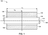
- FIG. 1 is a schematic representation of an axial cross-section of a system 100 in accordance with some embodiments of the present invention.
- the system 100 includes a shaft 110 and a journal bearing 120 for the shaft 110.
- the journal bearing has an inner surface 122 that defines a bore 124 to receive the shaft 110.
- the bore has a centerline, bore axis 126.
- the journal bearing has an outer surface 128.
- the journal bearing 120 is operatively coupled to the shaft 110 such that the journal bearing 120 and the shaft 110 operate as a pair during the operation of the system 100.
- the journal bearing 120 and the shaft 110 operating as a pair during the operation of the system 100 does not necessitate or indicate the existence of any physical bonding between the journal bearing 120 and the shaft 110.
- the joint-less, continuous body of the journal bearing 120 has a first end 132 and a second end 134, defining a length L 1 of the journal bearing as a shortest distance between the first end 132 and the second end 134.
- the journal bearing 120 supports shaft 110 during operation of the system 100 and helps the shaft 110 to rotate or oscillate freely inside the journal bearing 120 and transmit the radial load to a stationary structure on which the bearing 120 is mounted.
- FIG. 2 illustrates a cross-section 150 of the joint-less, continuous body of the journal bearing 120 in a direction that is perpendicular to the bore axis 126.
- the cross-section 150 of the joint-less, continuous body of the journal bearing illustrates the inner surface 122, the outer surface 128, and at least three angular sectors 160, 170, and 180, each of which is defined by two radii and respective arcs of the inner surface 122 and the outer surface 128.
- the angular sector 160 is an area of the joint-less, continuous body that is defined by the radii 153 and 154 and arcs of the inner surface 122 and the outer surface 128 between the radii 153 and 154.
- the angular sector 170 is an area defined by the radii 155 and 156 and arcs of the inner surface 122 and the outer surface 128 between the radii 155 and 156; and the angular sector 180 is an area defined by the radii 157 and 152 and arcs formed by the inner surface 122 and the outer surface 128 between the radii 157 and 152.
- the angular segment 160 has an angular span of ⁇
- the angular sector 170 has an angular span of ⁇
- the angular sector 180 has an angular span of ⁇ subtended by the respective arcs of the inner surface 122 (i.e., the central angle between respective pair of radii selected from radii 153, 154, 155, 156, 157, and 152).
- the angular spans of the different angular sectors may be designed purely based on the functionalities of the angular sectors and need not be designed to be axi-symmetric.
- a width "W 1 " of the journal bearing along a cross-section is a shortest distance in the cross-section between two opposite points in the outer surface 128 of the joint-less, continuous body of the journal bearing 120.
- a width "W2" of an angular sector along the cross-section 150 may be a shortest distance in the cross-section between the inner surface 122 and the outer surface 128 of the joint-less, continuous body.
- each of the angular sectors 160, 170, and 180 are different in microstructure, in composition, or in a combination of microstructure and composition from the other two angular sectors.
- At least two of the angular sectors 160, 170, or 180 extend along the length L 1 (illustrated in FIG. 1 ) of the joint-less, continuous body.
- a cross-section at any distance in the length L 1 will have at least two of the at least three angular sectors.
- the cross- section 150 may be at any distance L2 between the first end 132 and the second end 134 of the body of the journal bearing 120 illustrated in FIG. 1 .
- the joint-less, continuous body need not have at least three angular sectors in all the cross-sections perpendicular to the bore axis. However, it comprises at least three angular sectors in at least one of the cross-sections perpendicular to the bore axis. In some embodiments, the joint-less, continuous body comprises at least three angular sectors in all the cross-sections perpendicular to the bore axis. In some embodiments, the distance L 2 , shown in FIG. 1 , of the cross-section from the first end 130 is at least 10% of the length L 1 of the body of the journal bearing 120.
- the distance L 2 of the cross-section is half of the length L 1 , thus defining a cross-section at the center of the joint-less, continuous body of the journal bearing 120.
- a cross-section 150 at any distance in the length L 1 will have all of the at least three angular sectors.
- the joint-less, continuous body of the journal bearing may have any outer and/or inner shapes that may include further optional structural variations, such as, for example, grooves, holes, and/or lobes.
- the journal bearing may have any additional outer and/or inner structural extensions to the joint- less, continuous body, such as, for example, extensions of grooves, holes, and/or lobes that may form non-continuous discrete tilt pads.
- the joint-less, continuous body has a cylindrical outer surface and a cylindrical inner surface.
- the joint-less, continuous body is a joint-less, continuous cylindrical body with a circular or an elliptical bore.
- the inner surface of the cylindrical body may define a circular bore or an elliptical bore aiding operability of the combination of the shaft and the journal bearing.
- the at least three angular sectors of the cross-section 150 may have any angular spans that enhance functionalities of the at least three angular sectors and improves overall performance of the journal bearing.
- a greater angular span of a particular angular sector may enhance a functionality associated with that angular sector.
- each of the at least three angular sectors include an angular span of at least 5°.
- the number of angular sectors may vary in different cross-sections perpendicular to the bore axis. In some embodiments, depending on the functionalities of each of the angular sectors, an angular span of a particular angular sector may be varied in different cross-sections perpendicular to the bore axis. In some embodiments, an angular span of a particular angular sector may be continuously varied along the length of the joint-less, continuous body. In some embodiments, an angular span of a particular angular sector may be continuously varied throughout the length of the joint- less, continuous body.
- an angular span of an angular sector is continuously decreased from the central cross-section to the first end 132 and the second end 134. In another non-limiting example, an angular span of an angular sector is continuously decreased from the first end 132 to the second end 134.
- a location of an angular sector with respect to the bottom of a stationary journal bearing may be different in different cross-sections along the length L 1 of the body.
- a location of an angular sector is continuously tilted in successive cross-sections while measured from the central cross-section to the first end 132 and/or the second end 134. In another non-limiting example, a location of an angular sector is tilted continuously in successive cross-sections while measured from the first end 132 to the second end 134.
- the at least three angular sectors of the cross-section 150 are adjacent to each other. In some embodiments, having three angular sectors as illustrated in FIG. 2 , the three angular sectors are blended with each other at their intersections 190. In the embodiments having more than three angular sectors, each of the angular sectors are blended with both the neighbors in the intersections 190 thereof. Thus, the intersection 190 of any two angular sectors are in a diffused state without having any specific border or joints within the intersection 190 to demarcate the angular sectors. Further, the blending of the neighboring angular sectors in the intersection 190 leads to a monolithic joint-less, continuous body having the two neighboring angular sectors.
- the monolithic architecture ensures that functionally distinguishable aspects of each of the neighboring sectors are all interwoven via blending, rather than containing architecturally separate components.
- the blending of the neighboring angular sectors in the intersections 190 ensures a continuous, strong journal bearing 120 without rendering the intersections 190 of the angular sectors as weak points susceptible to cracking or breaking during operation.
- the angular sectors may be blended with one another in the intersections 190 in various ways.
- the intersections include at least one of a microstructural gradation or a compositional gradation along an angular span, as shown, for example, in FIG. 3.
- FIG. 3 illustrates a graded intersection 194 of the two angular sectors 170 and 180 such that a density of the material of the angular sector 170 gradually decreases and a density of the material of the angular sector 180 gradually increases in the intersection 194 when moving from the angular sector 170 to the angular sector 180 in between the radii 156 and 157.
- a first angular sector is compositionally different from a neighboring, second angular sector
- the intersection of the first angular sector and the neighboring, second angular sector may have a compositional gradation.
- the compositional gradation may be formed by the gradual variation of the composition of the intersection from the composition of the first angular sector to the composition of the second angular sector, along an angular span.
- the two neighboring angular sectors are microstructurally different from each other, then their intersection may have a microstructural variation along an angular span.
- Non-limiting examples of a microstructural difference between any two angular sectors include differences in grain size, grain shape, intergranular boundary, or porosity.
- the intersection 190 of the any two angular sectors span a finite angular span ⁇ of at least 1° as shown in FIG. 2 .
- the continuous intersections of the angular sectors in the journal bearings disclosed herein are in contrast to the conventional two halves of the split bearings touching each other or mechanically joined to function as the journal bearing.
- the continuous intersections of the angular sectors are particularly advantageous to have seamless property variation from one angular sector to another without compromising the macrostructural integrity of the journal bearing or introducing abrupt microstructural and compositional variations in the journal bearing.
- journal bearing may be designed to suit various functionalities that may be required for the function, or advantageous for the enhanced performance of the journal bearing in comparison with the conventional journal bearings.
- functionalities of the journal bearing include load bearing, wear resistance, corrosion resistance, erosion resistance, scuffing resistance, seizure resistance, cavitation resistance, heat-dissipation, lubricant storage, lubricant dispersal to the surface of the shaft during operation, embeddability of small foreign particles in the lubricant, and measurement of various parameters, such as, for example, temperature, wear, amount of lubrication in between the journal bearing and the shaft.
- a load bearing capacity of the journal bearing is the maximum value of cycling stress that the journal bearing can withstand.
- the journal bearing is desired to have a high load bearing capacity even after numerous number of cycles of the shaft during operation.
- the cycling stresses that are applied to the journal bearings are a result of combustion and inertia forces developed in an internal combustion engine employing the journal bearing.
- fatigue cracks may develop in the journal bearing, if the load on the journal bearing exceeds the fatigue strength of the journal bearing. These fatigue cracks may generate at sub surface and can spread to surface resulting in flaking of the material of the journal bearing.
- Wear resistance of a journal bearing is the ability of the material of the journal bearing to maintain its dimensional stability despite the presence of abrasive foreign particles in the lubricant and under the conditions of intermittent, direct contact between the journal bearing and shaft materials.
- Embeddability is the ability of the material of the journal bearing to entrap small foreign particles such as, for example, dirt, debris, dust, and abrasive residuals circulating in the lubricating oil and trap those particles beneath the inner surface of the journal bearing.
- Poor embeddability of a material of the journal bearing causes accelerated wear and produces scratches on the surfaces of the shaft and journal bearing, which can further lead to seizure.
- a sliding friction between the shaft and the journal bearing is normally reduced by an addition of a lubricant between the rubbing surfaces.
- Engine bearings are normally lubricated by motor oil when constantly supplied in sufficient amounts to the bearing's surfaces.
- Lubricated friction is characterized by the presence of a thin film of the pressurized lubricant (hydrodynamic or squeeze film) between the surfaces of the bearing and the journal.
- hydrodynamic journal bearings In general, many engineering applications have hydrodynamic journal bearings. In hydrodynamic journal bearings, high rotation speed at relatively low loads results in hydrodynamic friction, which is characterized by stable film of the lubricant between the rubbing surfaces. No contact between the surfaces occurs in hydrodynamic lubrication.
- the lubricant film keeps the surfaces of the bearing and the shaft apart due to hydrodynamic pressure generated by the lubricant squeezed through the convergent gap between the eccentric journal and the bearing.
- the lubricant may be continuously supplied to the contact surfaces of the journal bearing and the shaft, and hence it is desirable for the journal bearings to have a lubricant storage and /or a continuous supply of lubricant and further to have a design and process to supply the required amount of lubricant to the contact surfaces of the shaft and the journal bearing during operation.
- Heat generated in the journal bearings during operation should be effectively dissipated so that the equilibrium conditions of operation of the system are reached in a short time. Further, it is desirable to limit the generated average or equilibrium temperature such that the deterioration of the lubricant due to high thermal conditions is effectively controlled.
- the at least three angular sectors in the journal bearing include a load bearing sector, a heat dissipation sector, and a lubricant reservoir sector.
- the journal bearing 120 has at least one load bearing sector, at least one heat-dissipation sector, and at least one lubricant reservoir sector.
- Non-limiting examples of other angular sectors include one or more angular embeddable sector specifically developed to enable foreign particle embeddability, entrapping sector having pockets specifically constructed to trap foreign particles.
- the load bearing functionality of the journal bearings is accomplished by using a high strength material, such as, for example, steel to construct at least a lower half of the journal bearing.
- a high strength material such as, for example, steel
- the currently available journal bearings include the high-strength material as the major component of the at least lower half, even if the load bearing capability may be required only in a limited angular span of the lower half.
- at least one angular sector of the at least three angular sectors may be exclusively constructed for accomplishing the load bearing capability of the journal bearing without the need for other angular sectors to include the high strength load bearing material. This construction aids enhanced life and performance of the journal bearings.
- the at least three angular sectors may be constructed by any materials or any combination of materials that is best suited for the functionality requirement of the each of the at least three angular sectors.
- the load bearing sector may be constructed by a material that has high fatigue strength.
- Any adjacent angular sector, such as, for example, a heat-dissipation sector or a lubricant reservoir sector may be constructed by completely different materials than the load bearing sector, suiting the individual functionalities of the respective angular sectors.
- the load bearing sector may be constructed using a high-strength steel or any high strength alloy
- the heat-dissipation sector may be constructed of copper
- the lubricant reservoir sector may be constructed of a polymer having designed pores or micro channels to store and supply the lubricant.
- the load bearing sector of the journal bearing is a solid structure comprising a material selected from the group consisting of a metal, an alloy, a ceramic, a composite, or any combinations of the foregoing materials.
- Non-limiting examples for the material of the load bearing sector include iron or high fatigue strength steels.
- the load bearing sector of the journal bearing is at a location that is expected to get a maximum load of the shaft.
- the location that is expected to get a maximum load of the shaft during operation may be located at the direction of force F of the shaft, as shown, for example, in FIG. 4 .
- the direction of force of the shaft may be in the direction of gravitational force (i.e. bottom B in FIG. 4 ) during idle or low rotational speed conditions of the shaft.
- the direction of force may be in a slightly off position than the bottom B of a stationary journal bearing during operation of the system 100.
- the load bearing sector of the journal bearing is within the ⁇ 30° span from the bottom point of the journal bearing.
- a desired angular span of the load bearing sector depends on the expected variation in the direction of force of the shaft during operation of the system. In some embodiments, the angular span of the load bearing sector is less than 60°. In certain embodiments, the angular span of the load bearing sector is in a range from about 15 ° to about 40 °.
- the fatigue strength of the load bearing sector may be uniform throughout the load bearing sector.
- a hardness of the load bearing sector is desired to be maximum at the surface that comes into physical contact with the shaft as compared to the inner parts and the outer surface of the load bearing sector.
- the load bearing sector of the journal bearing is constructed such that the hardness of the load bearing sector is maximum at the inner surface of the journal bearing.
- a hardness of the load bearing sector decreases along a radial direction of the load bearing sector.
- the heat dissipation sector of the journal bearing may include any high thermally conducting material such that the heat is dissipated from the inner surface to the outer surface of the journal bearing.
- Non-limiting examples for the high thermal conductivity material of the heat dissipation sector include copper, aluminum, silver, gold, or graphite.
- the heat dissipation sector of the journal bearing includes a high thermal conductivity material.
- the heat dissipation sector of the journal bearing includes a solid structure comprising a network of high thermal conductivity metal channels, a solid structure comprising a miniature heat pipe, or any combinations of the foregoing.
- the heat dissipation sector may be majorly constructed of a high thermal conductivity solid structure.
- the heat dissipation sector includes a solid structure of low thermal conductivity or high thermal conductivity materials and further includes a network of high thermal conductivity metal channels that may be embedded in the solid structure.
- the heat dissipation sector having the solid structure may be designed to include miniature heat pipes that assist in rapid dissipation of the heat generated in the inner surface of the journal bearing.
- the heat dissipation achieved in the joint-less, continuous journal bearings is comparatively higher than the heat-dissipation achieved in the conventional bearings having cast iron body.
- a high thermal conductivity material may have a thermal conductivity greater than 100 W/m-K.
- the lubricant reservoir sector of the journal bearing may include a porous structure, that can retain the lubricant to be dispersed to the inner surface of the journal bearing and to the surface of the shaft that meets the journal bearing.
- the lubricant reservoir sector may further include pores or micro channels that connect the lubricant reservoir to the inner surface of the journal bearing such that the lubricant from the lubricant reservoir may be disposed to the inner surface in a desired manner and quantity.
- the lubricant reservoir sector is a porous structure including a plurality of pores such that a volume percentage of the plurality of pores increases along the radial direction of the lubricant reservoir sector.
- the number of pores in the lubricant reservoir sector may increase along the radial direction.
- the pore sizes may increase along the radial direction of the lubricant reservoir sector.
- a radially outer portion of the lubricant reservoir sector may have more number of pores and/or larger pore sizes as compared to a radially inner portion.
- sizes and number of pores in the radially inner portion of the lubricant reservoir sector controls the amount and manner of dispersion of the lubricant that is stored in the radially outer portion of the lubricant reservoir sector.
- a plurality of fine pores of the outer portion may connect to micro channels to carry the lubricant to the interface of the shaft and journal bearing.
- the lubricant reservoir sector may not span the entire length L 1 of the joint-less, continuous body of the journal bearing.
- the lubricant may be supplied to the contact surfaces of the shaft and the journal bearing during operation using surface energy based mechanism, such as, for example, capillary action of the micro channels.
- the functioning of the lubricant reservoir sector may be influenced by the force of gravity.
- the dispersion of the lubricant from the reservoir may be partially controlled by the gravity, in addition to one or more of the size, distribution, and volume fraction of the pores in the lubricant reservoir sector.
- the lubricant reservoir sector is placed in an upper part of the journal bearing.
- the lubricant reservoir sector of the journal bearing is located in a direction opposite to the direction of force, placing the lubricant reservoir sector in a direction opposite to the load bearing sector.
- the joint-less, continuous body of the journal bearing may be constructed by disposing one layer after the other layer in any particular direction of the journal bearing.
- the joint-less, continuous body of the journal bearing may be constructed lengthwise by disposing the layers to build up in a direction of the bore axis.
- the joint-less, continuous body of the journal bearing may be constructed widthwise by disposing the layers to build up in a direction perpendicular to the bore axis.
- a base layer having two or more angular sectors may be deposited using the materials of the two or more angular sectors at precisely demarcated locations.
- the angular sectors and the intersections of the angular sectors may be controlled by depositing the specific materials for the angular sectors and a mixture of the specific materials in a desired ratio to the intersections.
- the materials may be added to increase the number of angular sectors. For example, if the second layer has three or more angular sectors, then the three or more materials corresponding to the three or more angular sectors may be deposited in a pre-determined manner.
- the various materials, their compositional, microstructural, and consistency, and position details may be pre-determined based on the requirement of the journal bearing during operation and stored in the form of software commands to be followed during manufacturing.
- the angular sectors may be homogeneous throughout the area of the angular sector or may include macrostructural, microstructural, or compositional inhomogeneity within the angular sectors.
- the angular sectors are inhomogeneous in radial, circumferential, or both in radial and circumferential directions.
- the macrostructural, microstructural, or compositional inhomogeneity in the angular sector may be introduced to enhance the performance and life of the journal bearing.
- An additive manufacturing method is particularly advantageous in forming the macrostructural, microstructural, and/or compositional inhomogeneity.
- the inhomogeneity in macrostructure, microstructure and composition may be easily achieved by designing the material to be deposited at different horizontal and vertical points.
- At least one of the angular sectors includes an inhomogeneous region along a radial direction of the at least one angular sector.
- the inhomogeneity may be gradual or may be abrupt, depending on the requirements of the angular sectors at the time of operation.
- a hardness of the load bearing sector may be decreased along a radial direction of the angular sector.
- a density and /or strength of the material of the load bearing sector may be reduced along the radial direction of the load bearing sector.
- the heat dissipation sector may include heat pipes or micro channels of high thermal conductivity material to carry the heat generated in the inner contacting surface of the journal bearing and/or from the load bearing sector.
- heat pipes or micro channels of high thermal conductivity material may vary the macrostructural appearance of the heat dissipation sector along the circumference of the heat dissipation sector.
- the lubricant reservoir sector has pores with higher percentage of pore volume in the outer portions of the lubricant reservoir sector connected to the micro channels that are present in the inner portions of the lubricant reservoir sector.
- the lubricant reservoir sector may further include micro channels opening in the inner surface of the journal bearing for lubricant delivery to the contact surface of shaft and journal bearing.
- At least one of the at least three angular sectors of the journal bearing may further include one or more other regions that may not be related to the primary function of the specific angular sector, but may aid or enhance the performance of the journal bearing.
- one or more angular sectors may include regions specifically developed to enable particle embeddability, pockets specifically constructed to trap foreign particles, thermocouples to monitor temperature and/or health conditions of the bearing, wear sensors to monitor the wear conditions of the bearing and shaft surfaces, or any combinations of the foregoing.
- at least one of the angular sectors of the journal bearing includes a sensor, a probe, a cooling fin, or any combinations of the foregoing.
- the load bearing sector is desired to be in the locations where the load of the shaft is experienced during operation. Therefore, the angular span of the load bearing sector may be designed to be limited to accommodate higher angular spans of the heat dissipation sector and the lubricant reservoir sector.
- the heat dissipation sector may, in some embodiments, desired to be in higher angular span than the load bearing sector.
- a higher angular span of the lubricant reservoir sector aids in higher amount of lubricant storage and further in efficient lubricant dispersion to the inner surface. Therefore, in some embodiments, it is desired to maximize the angular span of the lubricant dissipation sector, without compromising on the functionalities of other angular sectors of the journal bearing.
- an angular span of the load bearing sector is lower than at least one of an angular span of the heat dissipation sector or an angular span of the lubricant reservoir sector. Further, in certain embodiments, the angular span of the load bearing sector is lower than an angular span of the heat dissipation sector and the angular span of the heat dissipation sector is lower than the angular span of the lubricant reservoir sector. In some embodiments, the angular span of the lubricant reservoir sector is greater than 90°. In certain embodiments, the lubricant reservoir sector has an angular span greater than 120.
- the journal bearing may include more than one load bearing sectors, more than one heat dissipation sectors, and /or more than one lubricant reservoir sectors.
- the load bearing requirement is expected to be more in the angle 35 ° and at the angle 325 °, as measured from the bottom, during operation of the system 100
- dual load bearing sectors encompassing these angular regions may be constructed having any other desirable angular sector in the bottom region.
- a pair of heat dissipation sectors may be constructed on either side of the load bearing sector.
- multiple lubricant reservoir sectors may be constructed at different angles covering smaller angular spans at each location, yet meeting the lubrication requirement of the system 100.
- a combined angular span of all the load bearing sectors is less than a combined angular span of all the heat dissipation sectors and the combined angular span of all the heat dissipation sectors is less than a combined angular span of all the lubricant reservoir sectors.
- the at least three angular sectors of the journal bearing includes at least two heat dissipation sectors, and the combined angular span of the at least two heat dissipation sectors is in a range from about 25 ° to about 180 °.
- the load bearing sector is constructed to be located along a radial direction of force of the shaft
- the lubricant reservoir sector is constructed to be located opposite to the load bearing sector
- the at least two heat dissipation sectors are constructed such that the heat dissipation sectors neighbor both the load bearing sector and the lubricant reservoir sector in both sides.
- a journal bearing for a shaft includes a joint-less, continuous cylindrical body having an inner surface defining a bore to receive the shaft, and an outer surface.
- a cross-section of the joint- less, continuous body perpendicular to a bore axis includes four angular sectors.
- the four angular sectors include a load bearing sector, two heat dissipation sectors, and a lubricant reservoir sector. Each of these angular sectors extend along a length of the joint-less, continuous cylindrical body.
- the load bearing sector is located along a radial direction of force of the shaft, the lubricant reservoir sector is located opposite to the load bearing sector, and the two heat dissipation sectors neighbor the load bearing sector and the lubricant reservoir sector on both sides.
- the load bearing sector and the lubricant reservoir sector include at least one of a different microstructure, or a different composition than each of the neighboring heat dissipation sectors.
- an angular span of the load bearing sector is in a range from about 15° to about 40°
- a combined angular span of the two heat dissipation sectors is in a range from about 25° to about 180°
- an angular span of the lubricant reservoir sector is greater than 90°. This aspect is further described below using an example figure, FIG. 4 .
- the journal bearing 220 includes a joint-less, continuous cylindrical body having an inner surface 222 defining the bore 240 to receive the shaft 210, and an outer surface 224.
- the cross-section of the joint-less, continuous body perpendicular to a bore axis includes four angular sectors.
- the four angular sectors include a load bearing sector 232, two heat dissipation sectors 234 and 236, and a lubricant reservoir sector 238, each of these sectors extend along a length of the joint- less, continuous cylindrical body.
- the load bearing sector 232 is located along a radial direction of force of the shaft.
- the lubricant reservoir sector 238 is located opposite to the load bearing sector, and the two heat dissipation sectors 234 and 236 neighbor the load bearing sector 232 and the lubricant reservoir sector 238 in both sides.
- the load bearing sector 232 and the lubricant reservoir sector 238 include at least one of a different microstructure, or a different composition than each of neighboring heat dissipation sectors 234 and 236. Further, an angular span of the load bearing sector is in a range from about 15° to about 40°, a combined angular span of the two heat dissipation sectors is in a range from about 25° to about 180°, and an angular span of the lubricant reservoir sector is greater than 90°. In the illustrated FIG.
- the load bearing sector 232 spans a region from about angle 350° (denoted as ⁇ in FIG. 4 ) to about 30° (denoted as ⁇ in FIG. 4 ) when measured from bottom B and in the direction of rotation R of the shaft.
- the journal bearing further includes a sensor 270 embedded in one of the angular sectors, in the lubricant reservoir sector 238 in the example illustrated in FIG. 4 .
- Non-limiting examples of the sensor 270 includes temperature sensor and wear measurement sensor.
- the present disclosure provides a long-life, high-performance journal bearing by combining different materials at different locations of the journal bearing to obtain an enhanced design space and enhanced functionality of the journal bearings, further ensuring efficient reduction of multiple manufacturing and assembling steps.
Landscapes
- Engineering & Computer Science (AREA)
- General Engineering & Computer Science (AREA)
- Mechanical Engineering (AREA)
- Chemical & Material Sciences (AREA)
- Ceramic Engineering (AREA)
- Oil, Petroleum & Natural Gas (AREA)
- Sliding-Contact Bearings (AREA)
- Rolling Contact Bearings (AREA)
Applications Claiming Priority (1)
| Application Number | Priority Date | Filing Date | Title |
|---|---|---|---|
| IN201641042871 | 2016-12-16 |
Publications (2)
| Publication Number | Publication Date |
|---|---|
| EP3343053A1 true EP3343053A1 (de) | 2018-07-04 |
| EP3343053B1 EP3343053B1 (de) | 2020-02-05 |
Family
ID=60627573
Family Applications (1)
| Application Number | Title | Priority Date | Filing Date |
|---|---|---|---|
| EP17205970.1A Active EP3343053B1 (de) | 2016-12-16 | 2017-12-07 | Verbindungfreies durchgehendes radial-gleitlager |
Country Status (5)
| Country | Link |
|---|---|
| EP (1) | EP3343053B1 (de) |
| JP (1) | JP2018119677A (de) |
| KR (1) | KR20180070483A (de) |
| CN (1) | CN108204405B (de) |
| CA (1) | CA2987167A1 (de) |
Cited By (1)
| Publication number | Priority date | Publication date | Assignee | Title |
|---|---|---|---|---|
| CN114542324A (zh) * | 2022-02-28 | 2022-05-27 | 北京盈天航空动力科技有限公司 | 一种微小型涡喷发动机多孔质两相轴承及其转子支撑结构 |
Families Citing this family (1)
| Publication number | Priority date | Publication date | Assignee | Title |
|---|---|---|---|---|
| US11879523B1 (en) * | 2022-08-16 | 2024-01-23 | Rolls-Royce Deutschland Ltd & Co Kg | Planetary gear arrangement and journal pin for supporting gear |
Citations (9)
| Publication number | Priority date | Publication date | Assignee | Title |
|---|---|---|---|---|
| DE930004C (de) * | 1954-01-20 | 1955-07-07 | Josef Dr Blanderer | Gleitlager |
| GB1359595A (en) * | 1972-02-29 | 1974-07-10 | Vandervell Products Ltd | Bearings for railway vehicle axles |
| GB2022722A (en) * | 1978-06-06 | 1979-12-19 | Merisinter Spa | Sintered self lubricating beatings |
| JPS56171423U (de) * | 1980-05-23 | 1981-12-18 | ||
| DD155917A1 (de) * | 1980-12-31 | 1982-07-14 | Bernd Langer | Lager fuer hohe dynamische belastungen und verfahren zu dessen herstellung |
| US5120140A (en) * | 1989-10-24 | 1992-06-09 | Sankyo Seiki Mfg. Co., Ltd. | Sintered oil-impregnated bearing |
| EP1233197A1 (de) * | 2001-02-15 | 2002-08-21 | ROBERT BOSCH GmbH | Sintergleitlager mit mehreren Laufzonen |
| JP2004144255A (ja) * | 2002-10-28 | 2004-05-20 | Komatsu Ltd | 摺動部材とその製造方法 |
| US20090087126A1 (en) * | 2007-10-01 | 2009-04-02 | Saint-Gobain Performance Plastics Corporation | Bearings |
Family Cites Families (4)
| Publication number | Priority date | Publication date | Assignee | Title |
|---|---|---|---|---|
| JPH0976371A (ja) * | 1995-09-12 | 1997-03-25 | Mitsubishi Electric Corp | 多孔質プラスチック軸受およびその製造方法 |
| DE10312873A1 (de) * | 2003-03-22 | 2004-10-07 | Gkn Sinter Metals Gmbh | Sintergleitlager mit kontinuierlicher Variation der Bohrungsverdichtung |
| JP2012026504A (ja) * | 2010-07-22 | 2012-02-09 | Ntn Corp | 焼結含油軸受 |
| CN105545943A (zh) * | 2016-01-27 | 2016-05-04 | 苏州睿动电气科技有限公司 | 一种含油轴承 |
-
2017
- 2017-11-30 CA CA2987167A patent/CA2987167A1/en not_active Abandoned
- 2017-12-04 JP JP2017232273A patent/JP2018119677A/ja active Pending
- 2017-12-07 EP EP17205970.1A patent/EP3343053B1/de active Active
- 2017-12-14 KR KR1020170172082A patent/KR20180070483A/ko not_active Application Discontinuation
- 2017-12-15 CN CN201711360707.3A patent/CN108204405B/zh active Active
Patent Citations (9)
| Publication number | Priority date | Publication date | Assignee | Title |
|---|---|---|---|---|
| DE930004C (de) * | 1954-01-20 | 1955-07-07 | Josef Dr Blanderer | Gleitlager |
| GB1359595A (en) * | 1972-02-29 | 1974-07-10 | Vandervell Products Ltd | Bearings for railway vehicle axles |
| GB2022722A (en) * | 1978-06-06 | 1979-12-19 | Merisinter Spa | Sintered self lubricating beatings |
| JPS56171423U (de) * | 1980-05-23 | 1981-12-18 | ||
| DD155917A1 (de) * | 1980-12-31 | 1982-07-14 | Bernd Langer | Lager fuer hohe dynamische belastungen und verfahren zu dessen herstellung |
| US5120140A (en) * | 1989-10-24 | 1992-06-09 | Sankyo Seiki Mfg. Co., Ltd. | Sintered oil-impregnated bearing |
| EP1233197A1 (de) * | 2001-02-15 | 2002-08-21 | ROBERT BOSCH GmbH | Sintergleitlager mit mehreren Laufzonen |
| JP2004144255A (ja) * | 2002-10-28 | 2004-05-20 | Komatsu Ltd | 摺動部材とその製造方法 |
| US20090087126A1 (en) * | 2007-10-01 | 2009-04-02 | Saint-Gobain Performance Plastics Corporation | Bearings |
Cited By (1)
| Publication number | Priority date | Publication date | Assignee | Title |
|---|---|---|---|---|
| CN114542324A (zh) * | 2022-02-28 | 2022-05-27 | 北京盈天航空动力科技有限公司 | 一种微小型涡喷发动机多孔质两相轴承及其转子支撑结构 |
Also Published As
| Publication number | Publication date |
|---|---|
| KR20180070483A (ko) | 2018-06-26 |
| CA2987167A1 (en) | 2018-06-16 |
| CN108204405B (zh) | 2021-05-07 |
| EP3343053B1 (de) | 2020-02-05 |
| CN108204405A (zh) | 2018-06-26 |
| JP2018119677A (ja) | 2018-08-02 |
Similar Documents
| Publication | Publication Date | Title |
|---|---|---|
| KR100454659B1 (ko) | 윤활유포켓들을구비하는미끄럼베어링요소 | |
| JP2004211859A (ja) | すべり軸受 | |
| CA2917384C (en) | Retainer | |
| EP3343053B1 (de) | Verbindungfreies durchgehendes radial-gleitlager | |
| CN107178430B (zh) | 具有可变涂层的汽缸孔 | |
| US6120187A (en) | Plain bearing | |
| EP2495464B1 (de) | Trägerelement | |
| JP6263545B2 (ja) | 軸受基材とポリマー埋込体とを備える滑り軸受、及びそれを備えるエンジン | |
| CN105121849B (zh) | 斜盘式压缩机的半球滑块和斜盘式压缩机 | |
| KR102367180B1 (ko) | 반할 스러스트 베어링, 스러스트 베어링, 베어링 장치 및 내연 기관 | |
| JP2014126069A (ja) | 半割りスラスト軸受 | |
| JP5317376B2 (ja) | 内燃機関のクランク軸を支承する軸受装置 | |
| JP2018087583A (ja) | スラストワッシャ | |
| RU2347959C2 (ru) | Сферический подшипник скольжения и способ изготовления сферического подшипника скольжения | |
| JP6313683B2 (ja) | 斜板式コンプレッサの半球シューおよび斜板式コンプレッサ | |
| AU2020286909B2 (en) | A bearing with pads having cooling micro-channels therein, and method | |
| EP3607215A1 (de) | Achslager mit verbesserter effizienz | |
| RU2788249C1 (ru) | Подшипник с вкладышами, содержащими охлаждающие микроканалы, и способ | |
| JP6313681B2 (ja) | 斜板式コンプレッサの半球シューおよび斜板式コンプレッサ | |
| TW568985B (en) | Method for manufacturing slide bushes | |
| RU2006126551A (ru) | Сегмент подпятника осевого гидродинамического подшипника погружного насосного агрегата для добычи нефти | |
| JP2017082730A (ja) | 斜板式コンプレッサ | |
| CN117108623A (zh) | 轴承及制造方法 | |
| Sasaki | Surface Texturing for Friction Control: A Review on Existing Technology and Prospects | |
| JP5107972B2 (ja) | 内燃機関のクランク軸を支承する軸受装置 |
Legal Events
| Date | Code | Title | Description |
|---|---|---|---|
| PUAI | Public reference made under article 153(3) epc to a published international application that has entered the european phase |
Free format text: ORIGINAL CODE: 0009012 |
|
| STAA | Information on the status of an ep patent application or granted ep patent |
Free format text: STATUS: THE APPLICATION HAS BEEN PUBLISHED |
|
| AK | Designated contracting states |
Kind code of ref document: A1 Designated state(s): AL AT BE BG CH CY CZ DE DK EE ES FI FR GB GR HR HU IE IS IT LI LT LU LV MC MK MT NL NO PL PT RO RS SE SI SK SM TR |
|
| AX | Request for extension of the european patent |
Extension state: BA ME |
|
| STAA | Information on the status of an ep patent application or granted ep patent |
Free format text: STATUS: REQUEST FOR EXAMINATION WAS MADE |
|
| 17P | Request for examination filed |
Effective date: 20190104 |
|
| RBV | Designated contracting states (corrected) |
Designated state(s): AL AT BE BG CH CY CZ DE DK EE ES FI FR GB GR HR HU IE IS IT LI LT LU LV MC MK MT NL NO PL PT RO RS SE SI SK SM TR |
|
| RIC1 | Information provided on ipc code assigned before grant |
Ipc: F16C 33/14 20060101ALN20190607BHEP Ipc: F16C 33/24 20060101AFI20190607BHEP Ipc: F16C 33/10 20060101ALI20190607BHEP Ipc: F16C 33/12 20060101ALI20190607BHEP Ipc: F16C 37/00 20060101ALI20190607BHEP Ipc: F16C 17/02 20060101ALI20190607BHEP |
|
| RAP1 | Party data changed (applicant data changed or rights of an application transferred) |
Owner name: AI ALPINE US BIDCO INC. |
|
| RIC1 | Information provided on ipc code assigned before grant |
Ipc: F16C 17/02 20060101ALI20190708BHEP Ipc: F16C 33/14 20060101ALN20190708BHEP Ipc: F16C 33/12 20060101ALI20190708BHEP Ipc: F16C 33/24 20060101AFI20190708BHEP Ipc: F16C 33/10 20060101ALI20190708BHEP Ipc: F16C 37/00 20060101ALI20190708BHEP |
|
| GRAP | Despatch of communication of intention to grant a patent |
Free format text: ORIGINAL CODE: EPIDOSNIGR1 |
|
| STAA | Information on the status of an ep patent application or granted ep patent |
Free format text: STATUS: GRANT OF PATENT IS INTENDED |
|
| INTG | Intention to grant announced |
Effective date: 20190819 |
|
| GRAS | Grant fee paid |
Free format text: ORIGINAL CODE: EPIDOSNIGR3 |
|
| GRAA | (expected) grant |
Free format text: ORIGINAL CODE: 0009210 |
|
| STAA | Information on the status of an ep patent application or granted ep patent |
Free format text: STATUS: THE PATENT HAS BEEN GRANTED |
|
| AK | Designated contracting states |
Kind code of ref document: B1 Designated state(s): AL AT BE BG CH CY CZ DE DK EE ES FI FR GB GR HR HU IE IS IT LI LT LU LV MC MK MT NL NO PL PT RO RS SE SI SK SM TR |
|
| REG | Reference to a national code |
Ref country code: GB Ref legal event code: FG4D |
|
| REG | Reference to a national code |
Ref country code: AT Ref legal event code: REF Ref document number: 1230125 Country of ref document: AT Kind code of ref document: T Effective date: 20200215 |
|
| REG | Reference to a national code |
Ref country code: DE Ref legal event code: R096 Ref document number: 602017011355 Country of ref document: DE |
|
| REG | Reference to a national code |
Ref country code: IE Ref legal event code: FG4D |
|
| REG | Reference to a national code |
Ref country code: CH Ref legal event code: EP |
|
| REG | Reference to a national code |
Ref country code: NL Ref legal event code: MP Effective date: 20200205 |
|
| PG25 | Lapsed in a contracting state [announced via postgrant information from national office to epo] |
Ref country code: NO Free format text: LAPSE BECAUSE OF FAILURE TO SUBMIT A TRANSLATION OF THE DESCRIPTION OR TO PAY THE FEE WITHIN THE PRESCRIBED TIME-LIMIT Effective date: 20200505 Ref country code: FI Free format text: LAPSE BECAUSE OF FAILURE TO SUBMIT A TRANSLATION OF THE DESCRIPTION OR TO PAY THE FEE WITHIN THE PRESCRIBED TIME-LIMIT Effective date: 20200205 Ref country code: PT Free format text: LAPSE BECAUSE OF FAILURE TO SUBMIT A TRANSLATION OF THE DESCRIPTION OR TO PAY THE FEE WITHIN THE PRESCRIBED TIME-LIMIT Effective date: 20200628 Ref country code: RS Free format text: LAPSE BECAUSE OF FAILURE TO SUBMIT A TRANSLATION OF THE DESCRIPTION OR TO PAY THE FEE WITHIN THE PRESCRIBED TIME-LIMIT Effective date: 20200205 |
|
| REG | Reference to a national code |
Ref country code: LT Ref legal event code: MG4D |
|
| PG25 | Lapsed in a contracting state [announced via postgrant information from national office to epo] |
Ref country code: GR Free format text: LAPSE BECAUSE OF FAILURE TO SUBMIT A TRANSLATION OF THE DESCRIPTION OR TO PAY THE FEE WITHIN THE PRESCRIBED TIME-LIMIT Effective date: 20200506 Ref country code: LV Free format text: LAPSE BECAUSE OF FAILURE TO SUBMIT A TRANSLATION OF THE DESCRIPTION OR TO PAY THE FEE WITHIN THE PRESCRIBED TIME-LIMIT Effective date: 20200205 Ref country code: SE Free format text: LAPSE BECAUSE OF FAILURE TO SUBMIT A TRANSLATION OF THE DESCRIPTION OR TO PAY THE FEE WITHIN THE PRESCRIBED TIME-LIMIT Effective date: 20200205 Ref country code: IS Free format text: LAPSE BECAUSE OF FAILURE TO SUBMIT A TRANSLATION OF THE DESCRIPTION OR TO PAY THE FEE WITHIN THE PRESCRIBED TIME-LIMIT Effective date: 20200605 Ref country code: HR Free format text: LAPSE BECAUSE OF FAILURE TO SUBMIT A TRANSLATION OF THE DESCRIPTION OR TO PAY THE FEE WITHIN THE PRESCRIBED TIME-LIMIT Effective date: 20200205 Ref country code: BG Free format text: LAPSE BECAUSE OF FAILURE TO SUBMIT A TRANSLATION OF THE DESCRIPTION OR TO PAY THE FEE WITHIN THE PRESCRIBED TIME-LIMIT Effective date: 20200505 |
|
| PG25 | Lapsed in a contracting state [announced via postgrant information from national office to epo] |
Ref country code: NL Free format text: LAPSE BECAUSE OF FAILURE TO SUBMIT A TRANSLATION OF THE DESCRIPTION OR TO PAY THE FEE WITHIN THE PRESCRIBED TIME-LIMIT Effective date: 20200205 |
|
| PG25 | Lapsed in a contracting state [announced via postgrant information from national office to epo] |
Ref country code: ES Free format text: LAPSE BECAUSE OF FAILURE TO SUBMIT A TRANSLATION OF THE DESCRIPTION OR TO PAY THE FEE WITHIN THE PRESCRIBED TIME-LIMIT Effective date: 20200205 Ref country code: LT Free format text: LAPSE BECAUSE OF FAILURE TO SUBMIT A TRANSLATION OF THE DESCRIPTION OR TO PAY THE FEE WITHIN THE PRESCRIBED TIME-LIMIT Effective date: 20200205 Ref country code: CZ Free format text: LAPSE BECAUSE OF FAILURE TO SUBMIT A TRANSLATION OF THE DESCRIPTION OR TO PAY THE FEE WITHIN THE PRESCRIBED TIME-LIMIT Effective date: 20200205 Ref country code: RO Free format text: LAPSE BECAUSE OF FAILURE TO SUBMIT A TRANSLATION OF THE DESCRIPTION OR TO PAY THE FEE WITHIN THE PRESCRIBED TIME-LIMIT Effective date: 20200205 Ref country code: DK Free format text: LAPSE BECAUSE OF FAILURE TO SUBMIT A TRANSLATION OF THE DESCRIPTION OR TO PAY THE FEE WITHIN THE PRESCRIBED TIME-LIMIT Effective date: 20200205 Ref country code: SK Free format text: LAPSE BECAUSE OF FAILURE TO SUBMIT A TRANSLATION OF THE DESCRIPTION OR TO PAY THE FEE WITHIN THE PRESCRIBED TIME-LIMIT Effective date: 20200205 Ref country code: EE Free format text: LAPSE BECAUSE OF FAILURE TO SUBMIT A TRANSLATION OF THE DESCRIPTION OR TO PAY THE FEE WITHIN THE PRESCRIBED TIME-LIMIT Effective date: 20200205 Ref country code: SM Free format text: LAPSE BECAUSE OF FAILURE TO SUBMIT A TRANSLATION OF THE DESCRIPTION OR TO PAY THE FEE WITHIN THE PRESCRIBED TIME-LIMIT Effective date: 20200205 |
|
| REG | Reference to a national code |
Ref country code: DE Ref legal event code: R097 Ref document number: 602017011355 Country of ref document: DE |
|
| REG | Reference to a national code |
Ref country code: AT Ref legal event code: MK05 Ref document number: 1230125 Country of ref document: AT Kind code of ref document: T Effective date: 20200205 |
|
| PLBE | No opposition filed within time limit |
Free format text: ORIGINAL CODE: 0009261 |
|
| STAA | Information on the status of an ep patent application or granted ep patent |
Free format text: STATUS: NO OPPOSITION FILED WITHIN TIME LIMIT |
|
| 26N | No opposition filed |
Effective date: 20201106 |
|
| PG25 | Lapsed in a contracting state [announced via postgrant information from national office to epo] |
Ref country code: IT Free format text: LAPSE BECAUSE OF FAILURE TO SUBMIT A TRANSLATION OF THE DESCRIPTION OR TO PAY THE FEE WITHIN THE PRESCRIBED TIME-LIMIT Effective date: 20200205 Ref country code: AT Free format text: LAPSE BECAUSE OF FAILURE TO SUBMIT A TRANSLATION OF THE DESCRIPTION OR TO PAY THE FEE WITHIN THE PRESCRIBED TIME-LIMIT Effective date: 20200205 |
|
| PG25 | Lapsed in a contracting state [announced via postgrant information from national office to epo] |
Ref country code: PL Free format text: LAPSE BECAUSE OF FAILURE TO SUBMIT A TRANSLATION OF THE DESCRIPTION OR TO PAY THE FEE WITHIN THE PRESCRIBED TIME-LIMIT Effective date: 20200205 Ref country code: SI Free format text: LAPSE BECAUSE OF FAILURE TO SUBMIT A TRANSLATION OF THE DESCRIPTION OR TO PAY THE FEE WITHIN THE PRESCRIBED TIME-LIMIT Effective date: 20200205 |
|
| REG | Reference to a national code |
Ref country code: CH Ref legal event code: PL |
|
| PG25 | Lapsed in a contracting state [announced via postgrant information from national office to epo] |
Ref country code: MC Free format text: LAPSE BECAUSE OF FAILURE TO SUBMIT A TRANSLATION OF THE DESCRIPTION OR TO PAY THE FEE WITHIN THE PRESCRIBED TIME-LIMIT Effective date: 20200205 |
|
| REG | Reference to a national code |
Ref country code: BE Ref legal event code: MM Effective date: 20201231 |
|
| PG25 | Lapsed in a contracting state [announced via postgrant information from national office to epo] |
Ref country code: LU Free format text: LAPSE BECAUSE OF NON-PAYMENT OF DUE FEES Effective date: 20201207 Ref country code: IE Free format text: LAPSE BECAUSE OF NON-PAYMENT OF DUE FEES Effective date: 20201207 Ref country code: FR Free format text: LAPSE BECAUSE OF NON-PAYMENT OF DUE FEES Effective date: 20201231 |
|
| PG25 | Lapsed in a contracting state [announced via postgrant information from national office to epo] |
Ref country code: CH Free format text: LAPSE BECAUSE OF NON-PAYMENT OF DUE FEES Effective date: 20201231 Ref country code: LI Free format text: LAPSE BECAUSE OF NON-PAYMENT OF DUE FEES Effective date: 20201231 |
|
| PG25 | Lapsed in a contracting state [announced via postgrant information from national office to epo] |
Ref country code: TR Free format text: LAPSE BECAUSE OF FAILURE TO SUBMIT A TRANSLATION OF THE DESCRIPTION OR TO PAY THE FEE WITHIN THE PRESCRIBED TIME-LIMIT Effective date: 20200205 Ref country code: MT Free format text: LAPSE BECAUSE OF FAILURE TO SUBMIT A TRANSLATION OF THE DESCRIPTION OR TO PAY THE FEE WITHIN THE PRESCRIBED TIME-LIMIT Effective date: 20200205 Ref country code: CY Free format text: LAPSE BECAUSE OF FAILURE TO SUBMIT A TRANSLATION OF THE DESCRIPTION OR TO PAY THE FEE WITHIN THE PRESCRIBED TIME-LIMIT Effective date: 20200205 |
|
| PG25 | Lapsed in a contracting state [announced via postgrant information from national office to epo] |
Ref country code: MK Free format text: LAPSE BECAUSE OF FAILURE TO SUBMIT A TRANSLATION OF THE DESCRIPTION OR TO PAY THE FEE WITHIN THE PRESCRIBED TIME-LIMIT Effective date: 20200205 Ref country code: AL Free format text: LAPSE BECAUSE OF FAILURE TO SUBMIT A TRANSLATION OF THE DESCRIPTION OR TO PAY THE FEE WITHIN THE PRESCRIBED TIME-LIMIT Effective date: 20200205 |
|
| PG25 | Lapsed in a contracting state [announced via postgrant information from national office to epo] |
Ref country code: BE Free format text: LAPSE BECAUSE OF NON-PAYMENT OF DUE FEES Effective date: 20201231 |
|
| P01 | Opt-out of the competence of the unified patent court (upc) registered |
Effective date: 20230602 |
|
| PGFP | Annual fee paid to national office [announced via postgrant information from national office to epo] |
Ref country code: GB Payment date: 20231121 Year of fee payment: 7 |
|
| PGFP | Annual fee paid to national office [announced via postgrant information from national office to epo] |
Ref country code: DE Payment date: 20231121 Year of fee payment: 7 |