EP3342971B1 - Window or door with a sash with a glass substrate - Google Patents
Window or door with a sash with a glass substrate Download PDFInfo
- Publication number
- EP3342971B1 EP3342971B1 EP17208730.6A EP17208730A EP3342971B1 EP 3342971 B1 EP3342971 B1 EP 3342971B1 EP 17208730 A EP17208730 A EP 17208730A EP 3342971 B1 EP3342971 B1 EP 3342971B1
- Authority
- EP
- European Patent Office
- Prior art keywords
- corner
- window
- profiles
- legs
- glass support
- Prior art date
- Legal status (The legal status is an assumption and is not a legal conclusion. Google has not performed a legal analysis and makes no representation as to the accuracy of the status listed.)
- Active
Links
- 239000011521 glass Substances 0.000 title claims description 96
- 239000000758 substrate Substances 0.000 title 1
- 239000002184 metal Substances 0.000 claims description 21
- 239000011324 bead Substances 0.000 claims description 11
- 239000000853 adhesive Substances 0.000 claims description 5
- 230000001070 adhesive effect Effects 0.000 claims description 4
- 238000004519 manufacturing process Methods 0.000 claims description 2
- 230000000284 resting effect Effects 0.000 claims 1
- 238000009413 insulation Methods 0.000 description 6
- 239000000463 material Substances 0.000 description 5
- 229910000831 Steel Inorganic materials 0.000 description 4
- 238000009434 installation Methods 0.000 description 4
- 229910001092 metal group alloy Inorganic materials 0.000 description 4
- 239000010959 steel Substances 0.000 description 4
- 239000002131 composite material Substances 0.000 description 3
- 238000010276 construction Methods 0.000 description 3
- 230000006641 stabilisation Effects 0.000 description 3
- 238000011105 stabilization Methods 0.000 description 3
- XLYOFNOQVPJJNP-UHFFFAOYSA-N water Substances O XLYOFNOQVPJJNP-UHFFFAOYSA-N 0.000 description 3
- 238000005452 bending Methods 0.000 description 2
- 238000013461 design Methods 0.000 description 2
- 238000011161 development Methods 0.000 description 2
- 238000007789 sealing Methods 0.000 description 2
- 230000004308 accommodation Effects 0.000 description 1
- 238000004026 adhesive bonding Methods 0.000 description 1
- 238000004140 cleaning Methods 0.000 description 1
- 238000009833 condensation Methods 0.000 description 1
- 230000005494 condensation Effects 0.000 description 1
- 238000002474 experimental method Methods 0.000 description 1
- 230000002093 peripheral effect Effects 0.000 description 1
- 230000008092 positive effect Effects 0.000 description 1
- 238000004080 punching Methods 0.000 description 1
- 238000005096 rolling process Methods 0.000 description 1
- 238000012549 training Methods 0.000 description 1
- 238000012546 transfer Methods 0.000 description 1
Images


Classifications
-
- E—FIXED CONSTRUCTIONS
- E06—DOORS, WINDOWS, SHUTTERS, OR ROLLER BLINDS IN GENERAL; LADDERS
- E06B—FIXED OR MOVABLE CLOSURES FOR OPENINGS IN BUILDINGS, VEHICLES, FENCES OR LIKE ENCLOSURES IN GENERAL, e.g. DOORS, WINDOWS, BLINDS, GATES
- E06B3/00—Window sashes, door leaves, or like elements for closing wall or like openings; Layout of fixed or moving closures, e.g. windows in wall or like openings; Features of rigidly-mounted outer frames relating to the mounting of wing frames
- E06B3/54—Fixing of glass panes or like plates
- E06B3/5409—Means for locally spacing the pane from the surrounding frame
-
- E—FIXED CONSTRUCTIONS
- E06—DOORS, WINDOWS, SHUTTERS, OR ROLLER BLINDS IN GENERAL; LADDERS
- E06B—FIXED OR MOVABLE CLOSURES FOR OPENINGS IN BUILDINGS, VEHICLES, FENCES OR LIKE ENCLOSURES IN GENERAL, e.g. DOORS, WINDOWS, BLINDS, GATES
- E06B3/00—Window sashes, door leaves, or like elements for closing wall or like openings; Layout of fixed or moving closures, e.g. windows in wall or like openings; Features of rigidly-mounted outer frames relating to the mounting of wing frames
- E06B3/54—Fixing of glass panes or like plates
-
- E—FIXED CONSTRUCTIONS
- E06—DOORS, WINDOWS, SHUTTERS, OR ROLLER BLINDS IN GENERAL; LADDERS
- E06B—FIXED OR MOVABLE CLOSURES FOR OPENINGS IN BUILDINGS, VEHICLES, FENCES OR LIKE ENCLOSURES IN GENERAL, e.g. DOORS, WINDOWS, BLINDS, GATES
- E06B3/00—Window sashes, door leaves, or like elements for closing wall or like openings; Layout of fixed or moving closures, e.g. windows in wall or like openings; Features of rigidly-mounted outer frames relating to the mounting of wing frames
- E06B3/04—Wing frames not characterised by the manner of movement
- E06B3/263—Frames with special provision for insulation
- E06B3/2632—Frames with special provision for insulation with arrangements reducing the heat transmission, other than an interruption in a metal section
-
- E—FIXED CONSTRUCTIONS
- E06—DOORS, WINDOWS, SHUTTERS, OR ROLLER BLINDS IN GENERAL; LADDERS
- E06B—FIXED OR MOVABLE CLOSURES FOR OPENINGS IN BUILDINGS, VEHICLES, FENCES OR LIKE ENCLOSURES IN GENERAL, e.g. DOORS, WINDOWS, BLINDS, GATES
- E06B3/00—Window sashes, door leaves, or like elements for closing wall or like openings; Layout of fixed or moving closures, e.g. windows in wall or like openings; Features of rigidly-mounted outer frames relating to the mounting of wing frames
- E06B3/96—Corner joints or edge joints for windows, doors, or the like frames or wings
- E06B3/964—Corner joints or edge joints for windows, doors, or the like frames or wings using separate connection pieces, e.g. T-connection pieces
-
- E—FIXED CONSTRUCTIONS
- E06—DOORS, WINDOWS, SHUTTERS, OR ROLLER BLINDS IN GENERAL; LADDERS
- E06B—FIXED OR MOVABLE CLOSURES FOR OPENINGS IN BUILDINGS, VEHICLES, FENCES OR LIKE ENCLOSURES IN GENERAL, e.g. DOORS, WINDOWS, BLINDS, GATES
- E06B7/00—Special arrangements or measures in connection with doors or windows
- E06B7/16—Sealing arrangements on wings or parts co-operating with the wings
- E06B7/22—Sealing arrangements on wings or parts co-operating with the wings by means of elastic edgings, e.g. elastic rubber tubes; by means of resilient edgings, e.g. felt or plush strips, resilient metal strips
-
- E—FIXED CONSTRUCTIONS
- E06—DOORS, WINDOWS, SHUTTERS, OR ROLLER BLINDS IN GENERAL; LADDERS
- E06B—FIXED OR MOVABLE CLOSURES FOR OPENINGS IN BUILDINGS, VEHICLES, FENCES OR LIKE ENCLOSURES IN GENERAL, e.g. DOORS, WINDOWS, BLINDS, GATES
- E06B3/00—Window sashes, door leaves, or like elements for closing wall or like openings; Layout of fixed or moving closures, e.g. windows in wall or like openings; Features of rigidly-mounted outer frames relating to the mounting of wing frames
- E06B3/04—Wing frames not characterised by the manner of movement
- E06B3/263—Frames with special provision for insulation
- E06B3/2632—Frames with special provision for insulation with arrangements reducing the heat transmission, other than an interruption in a metal section
- E06B2003/26325—Frames with special provision for insulation with arrangements reducing the heat transmission, other than an interruption in a metal section the convection or radiation in a hollow space being reduced, e.g. by subdividing the hollow space
Definitions
- the invention relates to a window or a door according to the preamble of claim 1.
- the corner glass support (s) designed in this way make it possible in a simple manner to safely carry off the pane load even on a casement frame which has no main profile on its composite profiles towards the outside.
- This construction is particularly useful if the insulating profiles of the casement do not have a fixed connection to a main profile towards the exterior, but are covered by a respective main profile of the frame, which closes or covers the rebate space to an exterior and directly via a seal comes into contact with the surface element.
- a particularly compact arrangement which on the other hand allows the corner glass support to be formed with a greater wall thickness and / or the grooves, is achieved in that at least the support sections of both legs of the at least one corner glass support are wholly or partially in each case in a recess, in particular in one Insert the receiving chamber of the respective insulating profile of the two insulating profiles that abut one another at a corner.
- this configuration can also be provided for several or preferably all of the corner glass supports.
- a rectangular frame is preferably implemented, and four corners with four corner glass supports are provided, which are further preferably all of the same design. It also preferably measures that are related to one of the legs and its arrangement. It is then preferred that these measures or arrangements are provided on both legs of the respective corner glass supports in the same way and are formed if necessary.
- corner glass supports is formed in one piece and / or if one or more of the corner glass supports consist of a metal sheet, in particular a steel sheet. But it can also consist of a light metal or plastic or another sufficiently strong material that can withstand the loads in the corner area and is coordinated with it. It can also be designed as a cast part.
- the main profile consists of metal, in particular of a light metal or a light metal alloy, or of plastic and / or that the insulating profile consists of plastic.
- one or both legs of the respective corner glass support have one or more beads or grooves. These preferably run parallel to the main direction of extension of the two legs of the at least one corner glass support.
- a further optimal stabilization of the at least one corner glass support is achieved in a simple manner in that the one or more beads or grooves according to the preceding paragraph each extend continuously over the corner area and both of the legs and / or that each has one or more the beads or grooves are provided both in the respective fastening section and in the respective support section of both legs.
- the fastening sections of both legs of the at least one corner glass support are each fixed to the main profiles of the respective frame profiles of the casement, which also abut one another corner.
- support means such as one or more glass rebate blocks and / or an adhesive are formed to bear part of the weight of the surface element in this section to support the leg or legs of the corner glass support.
- the at least one corner glass support is fastened on one or preferably both of its legs with the fastening sections of these legs on the respective main profiles by hooking the fastening sections behind an undercut on the main profiles.
- the center seal is preferably also in direct contact with this, which is also advantageous with regard to thermal insulation.
- the invention also realizes a simple and advantageous method for producing a window or a sash according to one of the claims relating thereto, with the steps of claim 16. Further advantageous refinements, each of which has a positive effect on the construction, can be found in the remaining subclaims.
- window can be replaced synonymously with the term "door”. Only the frame is often not closed all round on a door, but extends only over three sides of the frame. Terms such as “vertical” and “horizontal” or “right” and “left” refer to the representation of the Fig. 1 and an installation position on a vertically aligned wall, in particular on an outer wall of a building. In this respect, they are relative to the respective installation position.
- the three or four spars of the frame or casement frame to be described - these spars are also referred to below as frame profiles or composite frame profiles - are constructed here completely or essentially the same.
- the window 100 shown is designed for installation in an opening in a wall of a building. It has a frame 200 and a wing 300 with a wing frame 301.
- the wing 300 or the wing frame 301 is relative movable to the frame 200, in particular pivotable about a horizontal axis X and / or rotatable about a vertical axis of rotation Y (coordinate system shown displaced).
- the frame 200 and the casement 301 consist of horizontal and vertical frame profiles 201, 202, 203, 204 and 302, 303, 304, 305.
- the frame of a door can also be open at the lower edge (not shown here).
- the sash frame 301 also surrounds and supports a surface element 306 like a disk.
- 5 and 6 each show a section through the circumferential window frame and an edge of the surface element, i.e. through one of the casement profiles 302 and one of the frame profiles 201 and through an edge region of the surface element 306 close to a corner of the frame, in an area in which a (even closer to be described) corner glass support 320 extends. It is preferably close to the corners of all of the casement profiles and the frame profiles in the manner of 5 or 6 and possibly the variants and options described for this purpose, so that the following description can be transferred accordingly to the further frame sections.
- a (frame) rebate space F is formed between the frame 200 and the sash 301 on at least three sides of the window frame or all the way round, in which the frame 200 and the sash 301 are at a defined distance from one another when the window 100 is closed (see 5 and 6 ).
- the rebate area F is opened when the sash 300 is opened and, when the window 100 is closed, is essentially closed except for the remaining (narrow) gap sections SII and SI between the frame 200 and the sash frame 301 (except for functional openings to be explained below).
- Rotary and / or swivel bearings are used to implement a relative movement between the frame 200 and the casement 301.
- a handle can be provided for operation.
- the frame profiles 201-204 and the sash profiles 302-305 are designed as composite profiles.
- the frame profiles are preferably made (see also 5 and 6 ) from at least two main profiles 206, 207, which are connected here in one or more levels by one or more insulating webs 208, 209.
- the main profiles are preferably designed as metal profiles, in particular made of light metal or a light metal alloy.
- the insulating bars are made of plastic.
- the window frame can also consist entirely or partially of other materials.
- the two main profiles or one of the main profiles and the one or more insulating webs can also form a one-piece frame profile, in particular made of plastic.
- one of the main profiles 206 faces an exterior space I and the other of the main profiles 207 of the frame faces an interior space II in an opening of a building.
- the casement profiles have a main profile 307 (directed towards the interior in a preferred orientation) and an insulating profile 308 made of plastic, which is attached to or is formed on the main profile 307.
- the main profile 307 and the insulating profile 308 can thus be formed in one piece or in several pieces.
- the main profile 307 preferably consists of metal, in particular of a light metal or a light metal alloy. But it can also consist of plastic or another material.
- the main profile 307 preferably consists of metal, in particular of a light metal or a light metal alloy. But it can also consist of plastic or another material.
- the main profile 307 is preferably towards the interior I and the insulating profile 308 of the casement 301 towards the exterior. But it is on the outside of the main profile 207 of the frame 200, which closes or covers the rebate area F to the outside space I.
- the insulating profile 308 is frame-like spaced on the outside from the glass pane or surface element 306.
- a glass rebate GF is formed between the insulating profile 308 and the glass pane 306.
- a center seal 210 can be inserted into the rebate space F between the frame 200 and the sash frame 301, which is fixed here in the frame 200 and which, when the sash is closed, can preferably rest against the sash frame 301 with a web 211 (cf. 6a and 6b ).
- a groove cover profile 212 can also be formed on the frame 200, which engages with a foot 213 in a mounting groove 214 of the frame and which can be used in sections in uncovered sections for fittings.
- the show Fig. 3 and 5 or 2 and 6 two different variants 212 and 212 'of the groove cover profile, which differ essentially in that they extend into the rebate space F from the mounting groove 214 to different lengths. They can have a lateral web 215 with which they bear against the center seal 211.
- the web 215 preferably forms a common plane or surface with the side of the center seal 210 facing away from the frame.
- the groove cover profile 212 'of Fig. 6 practically forms a larger hollow chamber with the frame 200. And a further hollow chamber is formed below the web 215 towards the frame 200. It therefore optimizes the thermal insulation of the structure well.
- the groove cover profile 212 is also advantageous in terms of thermal insulation due to the web 215, since a kind of hollow chamber is also formed below this web towards the frame. It can also be cleaned particularly well.
- the groove cover profiles 212 and 212 'thus differ on the one hand by their appearance. On the other hand, they offer further advantages in terms of good thermal insulation and / or in terms of the possibility of cleaning the fold area.
- a cover leg 216 is also formed, which in the closed state of the window covers the outer edge of the surface element 306 of the wing 300 to the outer space I.
- a glass contact seal 217 is formed on the inside of the cover leg 216 and bears in the edge portion of the surface element 306 when the wing 300 is closed. When opening the wing 300 to the interior, this seal remains on the cover leg 206 of the frame 200.
- the insulating profile 308 of the casement 301 is preferably connected to the main profile 307 of the casement 301 in a shear-resistant manner, for example in the section of a fastening foot 309, which can be inserted into a fastening groove 310 of the main profile 307 and can be fixed there in a thrust-resistant manner by rolling.
- no further main profile is preferably provided towards the interior.
- the two basic elements are the main profiles 307 and the insulating profiles 308 attached to them.
- An outer shell, in particular made of metal, or an outer profile, particularly made of metal, is not provided here.
- the frame 200 is preferably in direct contact with the glass contact seal 217 on the surface element 306 of the wing 300 in the closed state of the window.
- the insulating profile 308 of the casement 301 preferably has a hollow chamber 311. This is preferably outside the circumferential edge of the surface element 306.
- the insulating profile 308 also preferably has such an extension in the direction Z between the outer space I and the interior II (parallel to the edge of the surface element 306) that it extends the pane edge of the surface element 306 laterally to the glass rebate GF completely covered.
- the surface element 306 Towards one side - here towards the interior II - the surface element 306 preferably bears against the main profile 307 of the casement frame via a strip, in particular a glass retaining strip 312 made of plastic, which is attached to the main profile 307, which in this respect is the surface element 306 Interior covered in a (narrow) edge section.
- the glass holding strip 312 can have a sealing lip 313 on the side, which lies against the surface element 306 and advantageously realizes a seal between the glass holding strip 312 and the surface element 306 in this area.
- the glass retaining strip 312 is fastened to the main profile 307, preferably with a foot 316 inserted into a groove 315 of the main profile 307. Between the glass retaining strip 312 and the surface element 306 - in particular the glass pane - an edge bond 314 can be formed in this section all around in sections or completely in the manner of a frame his. This can be formed, for example, by a strip that is self-adhesive on both sides, or some other adhesive.
- corner glass support 320 in each case.
- a total of four of the corner glass supports 320 are preferably provided.
- the corner glass supports 302 each extend over a corner between adjoining casement profiles 302 and 303 or 303 and 304 or 304 and 305 or 305 and 302.
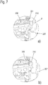
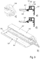
- Each corner glass support 320 is preferably designed as an angle element or angle support with two mutually angled, here right-angled legs 321, 322, which are connected to one another in a corner region 323 or preferably merge into one another ( Fig. 1b , Fig. 8 ).
- the legs 321, 322 are preferably constructed in the same way and are immediately connected to the corresponding wing frame profiles which abut one another at a corner.
- corner glass supports 320 is described below by way of example. All corner glass supports 320 can - but need not - advantageously be of the same design and corresponding and arranged on the respective casement profiles.
- the two legs 321, 322 of the corner glass support 320 are based on the corner area 323 (see Fig. 4 and 8th ) preferably at least 80 mm long.
- the maximum length is preferably ... mm.
- the corner glass support 320 is preferably formed in one piece from a metal sheet, in particular from a steel sheet. This preferably has a thickness of at least 1.4 mm - 8 mm.
- the two legs 321, 322 point each have a support section 321a, 322a for supporting the glass pane edge (this section rests on the respective insulating profile 308) and a fastening section 321b, 322b (which is fixed to the respective main profile 307 and, if appropriate, bears against it).
- These two sections 321a, 322a and 321b, 322b preferably each extend over the entire length of the two legs 321, 322, preferably in one piece or in one piece, directly next to one another and also over the corner area 323. This can be clearly seen in the cross-sectional views of FIG 5 and 6 .
- Fig. 4 and 8th referred.
- the corner glass supports 320 are each simply and advantageously suspended in the main profiles 307 of the frame profiles 302-305.
- the support sections 321a, 322a are advantageously spaced on the outside from the peripheral edge of the surface element 306.
- the metal sheet from which the corner glass support 320 is made preferably has one or more beads or grooves 324 in the support sections 321a, 322a and / or in the fastening sections 321b, 322b that run parallel to the respective frame profiles and the main direction of extension of the respective legs 321, 322 , 325 on.
- These one or more beads or grooves 324, 325 each serve to stiffen the two legs 321, 322 in order to protect them against bending, as could occur according to the prior art (see Fig. 1c ).
- the corner glass support 320 is so stable that such deflection no longer occurs to a relevant extent.
- both the legs 321, 322 and the corner area 323 preferably have grooves 324, 325 running continuously.
- the grooves 324, 325 are preferably at least 1.5 mm deep and 3 mm wide in order to ensure sufficient stabilization of the respective corner glass support 320.
- the grooves 324, 325 are particularly advantageous in this respect. However, they are not mandatory. If the metal sheet for the corner glass support 320 is chosen thick enough, it can also be omitted (not shown. The metal sheet can then advantageously be a steel sheet and at least a thickness of 2 mm or more with a weight of the surface element of 10 kg or more and one Have length of the frame profiles of more than 600 mm.
- the corner glass support (s) 320 are made of metal, in particular steel. However, they can also consist of a light metal or plastic or some other sufficiently strong material that can withstand the loads in the corner area and is coordinated with them.
- grooves 324, 325 are each formed at least in the support sections 321a, 322a of the two legs 321, 322, which lie like a frame outside the surface element 306. However, they are preferably also formed in the fastening sections 321b, 322b in order to stabilize them as well.
- a wall 326 of the hollow chambers 311 of the insulating profiles 308 of the respective corner of the sash frame 301 facing the glass rebate GF in the sections in which the adjacent sash frame profiles (for example 305, 302, see Fig. 4 ) the corner glass support 320 is to be arranged, has been removed from the insulating profiles 308 of the casement (see in particular Fig. 8 ).
- a receiving chamber 327 is advantageously formed in each of these sections, into which the support sections 321a, 322a of the two legs 321, 322 of the corner glass carrier 320 are inserted can. Since the corner glass carrier 320 lies in sections in each case (cleverly accommodated) in the receiving chambers 327, it is particularly advantageously possible to to make the corner glass support 320 relatively large in this section with a relatively large wall thickness, so to provide it with the grooves 324, 325 and / or to form it from a very thick or strong metal sheet, and to make it so stable that it is good against deflection is protected.
- support means such as one or more glass rebate blocks 328 ( Fig. 1b ) be designed to support the pane weight in this section on one or both legs 321, 322 of the corner glass support 320.
- an adhesive 328a ( 5, 6 between the corner glass support 320 and the pane edge of the surface element 306 can be provided in the region of one or both support sections of the legs 321, 322.
- corner glass carrier 320 is fastened to the main profile 307 on one or preferably both of its legs 321, 322 with the fastening sections 321b, 322b of these legs 321, 322.
- This fastening is preferably carried out directly simply by hanging the fastening sections 321b, 322b behind an undercut on the main profiles 307.
- the respective undercut can be formed by a free web on the respective main profiles 307 outside of hollow chambers 330, 331, 332 of the main profiles 307 placed one on the other (not shown here).
- the respective main profile 307 has one or more of the hollow chambers 330, 331, 332. It is then possible to use at least one or preferably two or even more of these hollow chambers 331, 332 for hanging the fastening sections 321b, 322b. In this way, the respective fastening section 321b, 322b of the two legs 321, 322 is accommodated, at least in sections, in a particularly space-saving manner and is nevertheless locked in place.
- fastening sections 321b, 322b have hook-like ends 335, 336 (see, for example, Fig. 5 and 8th ) exhibit.
- the hook-like ends 335, 336 are preferably designed as bends. It can also be provided that the grooves 325 also extend over the entire width of the fastening sections.
- the hook-like ends 335, 336 are hooked behind the undercuts (here the webs 337).
- the slot or slots 333 and / or 334 of the opened hollow chambers extend into the area of a miter cut.
- the corner glass support 320 is then inserted into the two sash profiles before the sash frame profiles are joined, in particular inserted into the slot (s) 333, 334, in particular with the hook-like end (s). Only then will the sash frame profiles to be connected via a corner (e.g. 302, 303) are assembled and / or joined in the corner area.
- At least one of the beads or grooves 325 is preferably additionally supported at another point on the respective main profile 307 of the casement 301.
- the respective fastening section 321b or 322b of the corner glass support 320 is stably hooked onto the respective associated main profile 302 to 305, and on the other hand, advantageously, a force transfer of part of the weight of the surface element 306 via the glass rebate blocks 328 and the corner glass support 320 into the main profiles 307 Casement profiles 302 to 305 possible.
- the fastening sections 321b, 322b are also preferably formed in one piece or connected to one another across the corner region 323. In this way, a very stable corner glass support 320 is created, which can be easily mounted on the casement 301, which does not impair the appearance of the casement 301 due to its clever accommodation, and is nevertheless designed to be very stable.
- the casement profiles 302-305 and the frame profiles 201-204 are preferably mitred in the corner area and placed at right angles to one another in these areas.
- corner connectors 340 are preferably used in order to additionally connect the sash frame profiles (for example 304, 305) which are placed next to one another in a corner.
- sash frame profiles for example 304, 305
- Fig. 11 This is exemplified in Fig. 11 to recognize.
- the corner connectors 340 are provided as angle elements, the legs of which are inserted into preferably otherwise free hollow chambers 330 of the two abutting sash profile sections (for example: 302, 33).
- corner connectors 340 can also optionally be used according to the invention.
- corner connectors 340 it is also possible according to the invention to dispense with the corner connectors 340 if the corner areas of the casement frames are adequately stabilized with the corner glass supports 320, for example on smaller windows 100 100 can also be achieved in this regard. It can easily be determined in an experiment whether additional corner connectors 340 should be used above or not.
- One or more holes 338, in particular bores in one or the two legs 321, 322 and / or corresponding holes 341 in the insulating profiles 308 can optimize the water drainage or serve to fix it, in particular in connection with one or more screws 339.
- Frame profiles 201, 202, 203, 204 Main profiles 206, 207 Insulating bars 208, 209 Center seal 210 web 211 Groove cover profile 212, 212 ' foot 213 Mounting groove 214 web 215 Cover leg 216 Glass system gasket 217 wing 300 Casement 301 Frame profiles 302, 303, 304, 305 Surface element 306 Main profile 307 Insulating profile 308 Mounting foot 309 Mounting groove 310 Hollow chamber 311 Glass retaining strip 312 Sealing lip 313 Edge gluing 314 Groove 315 foot 316 Corner glass support 320 leg 321.322 Support sections 321a, 322a Fastening sections 321b, 322b Corner area 323 Beads or
Description
Die Erfindung betrifft ein Fenster oder eine Tür nach dem Oberbegriff des Anspruchs 1.The invention relates to a window or a door according to the preamble of claim 1.
Fenster und Türen gattungsähnlicher Art sich aus der
Fenster und Türen der gattungsgemäßen Art sind aus der
Es ist die Aufgabe der Erfindung, dieses Problem mit einfachen technischen Mitteln zu lösen.It is the object of the invention to solve this problem with simple technical means.
Diese Aufgabe wird durch den Gegenstand des Anspruchs 1 gelöst.This object is solved by the subject matter of claim 1.
Weitere vorteilhafte Ausgestaltungen der Erfindung sind den übrigen Unteransprüchen zu entnehmen.Further advantageous embodiments of the invention can be found in the remaining subclaims.
Der oder die derart ausgebildeten Eckglasträger machen es auf einfache Weise möglich, die Scheibenlast auch an einem Flügelrahmen, der zum Außenraum hin kein Hauptprofil an seinen Verbundprofilen aufweist, sicher abzutragen. Zweckmäßig ist diese Konstruktion insbesondere dann, wenn die Isolierprofile des Flügelrahmens jeweils zum Außenraum hin keine feste Verbindung zu einem Hauptprofil aufweisen sondern von einem jeweiligen Hauptprofil des Blendrahmens abgedeckt sind, das jeweils den Falzraum zu einem Außenraum hin verschließt bzw. abdeckt und über eine Dichtung direkt an dem Flächenelement zur Anlage kommt.The corner glass support (s) designed in this way make it possible in a simple manner to safely carry off the pane load even on a casement frame which has no main profile on its composite profiles towards the outside. This construction is particularly useful if the insulating profiles of the casement do not have a fixed connection to a main profile towards the exterior, but are covered by a respective main profile of the frame, which closes or covers the rebate space to an exterior and directly via a seal comes into contact with the surface element.
Eine besonders kompakte Anordnung, die es andererseits erlaubt, den Eckglasträger mit einer größeren Wandstärke und/oder den Rillen auszubilden, wird dadurch erreicht, dass zumindest die Abstützabschnitte beider Schenkel des wenigstens einen Eckglasträgers ganz oder teilweise jeweils in einer Vertiefung, insbesondere in einer Aufnahmekammer, des jeweiligen Isolierprofils der beiden über Eck aneinander stoßenden Isolierprofile einliegen.A particularly compact arrangement, which on the other hand allows the corner glass support to be formed with a greater wall thickness and / or the grooves, is achieved in that at least the support sections of both legs of the at least one corner glass support are wholly or partially in each case in a recess, in particular in one Insert the receiving chamber of the respective insulating profile of the two insulating profiles that abut one another at a corner.
Sofern in den Unteransprüchen oder nebengeordneten Ansprüchen jeweils eine Ausbildung auf wenigstens einen Eckglasträger bezogen wird, kann diese Ausgestaltung auch bei mehreren oder vorzugsweise sämtlichen der Eckglasträger vorgesehen sein. Bevorzugt wird ein rechteckiger Rahmen realisiert, und es sind vier Ecken mit vier Eckglasträgern vorgesehen, die weiter vorzugsweise alle gleich ausgebildet sind. Es ferner vorzugsweise Maßnahmen, die in Bezug auf einen der Schenkel und dessen Anordnung bezogen werden. Dann ist bevorzugt, dass diese Maßnahmen oder Anordnungen an beiden Schenkeln der jeweiligen Eckglasträger gleich vorgesehen und ggf. ausgebildet sind.Insofar as training is referred to at least one corner glass support in each of the subclaims or independent claims, this configuration can also be provided for several or preferably all of the corner glass supports. A rectangular frame is preferably implemented, and four corners with four corner glass supports are provided, which are further preferably all of the same design. It also preferably measures that are related to one of the legs and its arrangement. It is then preferred that these measures or arrangements are provided on both legs of the respective corner glass supports in the same way and are formed if necessary.
Es ist zweckmäßig und konstruktiv einfach, wenn wenigstens einer der Eckglasträger einstückig ausgebildet ist und/oder wenn einer oder mehrere der Eckglasträger aus einem Metallblech, insbesondere einem Stahlblech bestehen. Er kann aber auch aus einem Leichtmetall oder aus Kunststoff oder einem sonstigen genügend festen Material bestehen, das den Belastungen im Eckbereich standhält- und auf diese abgestimmt ist. Auch eine Ausgestaltung als Gussteil ist realisierbar.It is expedient and structurally simple if at least one of the corner glass supports is formed in one piece and / or if one or more of the corner glass supports consist of a metal sheet, in particular a steel sheet. But it can also consist of a light metal or plastic or another sufficiently strong material that can withstand the loads in the corner area and is coordinated with it. It can also be designed as a cast part.
Es kann weiter vorteilhaft vorgesehen sein, dass das Hauptprofil aus Metall, insbesondere aus einem Leichtmetall oder einer Leichtmetalllegierung, oder aus Kunststoff besteht und/oder dass das Isolierprofil aus Kunststoff besteht.It can further advantageously be provided that the main profile consists of metal, in particular of a light metal or a light metal alloy, or of plastic and / or that the insulating profile consists of plastic.
Es ist weiter im Sinne einer nochmals verbesserten Stabilisierung des Eckglasträgers vorteilhaft, wenn einer oder beider Schenkel des jeweiligen Eckglasträgers eine oder mehrere Sicken bzw. Rillen aufweisen. Diese verlaufen bevorzugt parallel zur Haupterstreckungsrichtung der beiden Schenkel des wenigstens einen Eckglasträgers.It is further advantageous in the sense of a further improved stabilization of the corner glass support if one or both legs of the respective corner glass support have one or more beads or grooves. These preferably run parallel to the main direction of extension of the two legs of the at least one corner glass support.
Dabei wird auf einfache Weise eine nochmals optimalere Stabilisierung des wenigstens einen Eckglasträgers dadurch erreicht, dass die eine oder mehreren Sicken bzw. Rillen nach dem vorstehenden Absatz sich jeweils durchlaufend über den Eckbereich und beide der Schenkel erstrecken und/oder dass die je eine oder mehrere der Sicken bzw. Rillen sowohl in dem jeweiligen Befestigungsabschnitt als auch und in dem jeweiligen Abstützabschnitt beider Schenkel vorgesehen sind.A further optimal stabilization of the at least one corner glass support is achieved in a simple manner in that the one or more beads or grooves according to the preceding paragraph each extend continuously over the corner area and both of the legs and / or that each has one or more the beads or grooves are provided both in the respective fastening section and in the respective support section of both legs.
Es ist weiter vorteilhaft und sicher, wenn vorgesehen ist, dass nach einer Variante die Befestigungsabschnitte beider Schenkel des wenigstens einen Eckglasträgers jeweils an den Hauptprofilen der jeweiligen auch über Eck aneinander stoßenden Rahmenprofile des Flügelrahmens festgelegt sind.It is also advantageous and safe if it is provided that, according to a variant, the fastening sections of both legs of the at least one corner glass support are each fixed to the main profiles of the respective frame profiles of the casement, which also abut one another corner.
Es kann weiter vorgesehen sein, dass zwischen dem wenigstens einen Eckglasträger und dem Scheibenrand des Flächenelementes im Bereich eines oder beider der Schenkel jeweils Stützmittel wie einer oder mehrere Glasfalzklötze und/oder eine Verklebung ausgebildet sind, um einen Teil des Gewichts des Flächenelementes in diesem Abschnitt an dem oder den Schenkeln des Eckglasträgers abzustützen.It can further be provided that between the at least one corner glass support and the pane edge of the surface element in the region of one or both of the legs, support means such as one or more glass rebate blocks and / or an adhesive are formed to bear part of the weight of the surface element in this section to support the leg or legs of the corner glass support.
Es ist weiter konstruktiv einfach, wenn der wenigstens eine Eckglasträger an einem oder vorzugsweise beiden seiner Schenkel mit den Befestigungsabschnitten dieser Schenkel an den jeweiligen Hauptprofilen durch ein Einhaken der Befestigungsabschnitte jeweils hinter einen Hinterschnitt an den Hauptprofilen befestigt ist.It is also structurally simple if the at least one corner glass support is fastened on one or preferably both of its legs with the fastening sections of these legs on the respective main profiles by hooking the fastening sections behind an undercut on the main profiles.
Eine optionale und vorteilhafte Weiterbildung, die auch eine eigenständige Erfindung darstellt, besteht darin, dass bei einem Fenster oder Tür nach einem der darauf bezogenen Ansprüche oder nach dem Oberbegriff des Anspruchs 1 an dem Blendrahmen eine Mitteldichtung angeordnet ist und dass an dem Blendrahmen zumindest abschnittsweise ein Nutabdeckprofil angeordnet ist und dass ein Steg des Nutabdeckprofils fluchtend mit der Mitteldichtung ausgebildet ist, der vorzugsweise mit dem Blendrahmen gemeinsam eine Hohlkammer ausbildet. Denn derart werden der Falzbereich und insbesondere auch der Blendrahmen optisch vorteilhaft gestaltet und es wird eine gute Wärmedämmung möglich bzw. realisiert.An optional and advantageous further development, which also represents an independent invention, consists in that in the case of a window or door according to one of the claims relating thereto or according to the preamble of claim 1, a central seal is arranged on the frame and that at least in sections on the frame Groove cover profile is arranged and that a web of the groove cover profile is formed in alignment with the center seal, which preferably forms a hollow chamber together with the frame. This is because the fold area and in particular the window frame are designed to be optically advantageous and good thermal insulation is possible or implemented.
Vorzugsweise liegt ferner die Mitteldichtung im geschlossenen Zustand des Flügels an diesem direkt an, was ebenfalls hinsichtlich der Wärmedämmung vorteilhaft ist.In the closed state of the wing, the center seal is preferably also in direct contact with this, which is also advantageous with regard to thermal insulation.
Es ist sodann vorteilhaft, wenn der Steg mit der Oberseite der Mitteldichtung fluchtet und wenn das Nutabdeckprofil im Übrigen an seiner Oberseite mit dem Steg fluchtet oder im Übrigen unterhalb des Steges liegt. Die hinsichtlich der Optik und/oder der Reinigbarkeit und/oder der Wärmedämmung resultierenden Vorteile dieser Ausgestaltungen ergeben sich aus der nachfolgenden Figurenbeschreibung.It is then advantageous if the web is aligned with the top of the center seal and if the groove cover profile is otherwise aligned with the web on its top or otherwise lies below the web. The advantages of these configurations resulting from the optics and / or the cleanability and / or the thermal insulation result from the following description of the figures.
Die Erfindung realisiert schließlich auch ein einfaches und vorteilhaftes Verfahren zur Herstellung eines Fensters oder eines Flügels nach einem der darauf bezogenen Ansprüche mit den Schritten des Anspruchs 16.
Weitere vorteilhafte Ausgestaltungen, die sich jeweils positiv auf die Konstruktion auswirken, sind den übrigen Unteransprüchen zu entnehmen.Finally, the invention also realizes a simple and advantageous method for producing a window or a sash according to one of the claims relating thereto, with the steps of claim 16.
Further advantageous refinements, each of which has a positive effect on the construction, can be found in the remaining subclaims.
Nachfolgend wird die Erfindung anhand von Ausführungsbeispielen unter Bezug auf die Zeichnung näher beschrieben. Es zeigt:
- Fig. 1
- in a) eine Seitenansicht eines vereinfacht dargestellten Fensters, in b) eine schematische Darstellung eines Eckbereiches eines erfindungsgemäßen Fensters, wobei der Eckbereich ungefähr dem gestrichelt umkreisten Ausschnitt des Fensters aus a) entspricht, und in c) eine schematische Darstellung eines Eckbereiches eines bekannten Fensters, wobei der Eckbereich von der Größe her ungefähr einem Ausschnitt gemäß dem gestrichelt umkreisten Ausschnitt aus a) entspricht;
- Fig. 2
- einen Eckbereich eines ersten erfindungsgemäßen Fensters in einem geöffneten Zustand mit Flügelrahmen und Blendrahmen mit Mitteldichtung und Nutabdeckprofil;
- Fig. 3
- einen Eckbereich einer Variante des Fensters aus
Fig. 2 in einem geöffneten Zustand mit Flügelrahmen und Blendrahmen mit Mitteldichtung und einem alternativ ausgestalteten Nutabdeckprofil; - Fig. 4
- einen Eckbereich eines Flügelrahmens eines erfindungsgemäßen Fensters nach Art der
Fig. 2 ohne einen Beschlag und ohne Glasscheibe; - Fig. 5
- einen Schnitt durch ein Rahmenprofil eines Randbereichs des erfindungsgemäßen Fensters aus
Fig. 3 ; - Fig. 6
- in a) einen Schnitt durch ein Rahmenprofil eines Randbereichs der Variante des erfindungsgemäßen Fensters aus
Fig. 2 ; - Fig. 7
- in a) einen Ausschnitt aus
Fig. 5 bzw. 6 in einem Zustand, in welchem der Flügel in einer etwas geöffneten Position dargestellt ist und in b) den Ausschnitt aus a) in einem Zustand, in welchem der Flügel in einer geschlossenen Position dargestellt ist; - Fig. 8
- eine perspektivische Ansicht eines Flügelrahmens für ein erfindungsgemäßes Fensters mit einem separat dargestellten Glasträger;
- Fig. 9
- in a) einen Schnitt durch einen Flügelrahmen in einem für einen Glasträger vorgesehenen Abschnitt ohne den Glasträger; in b) eine perspektivische Ansicht eines Abschnitts des Flügelrahmens aus a), in c) eine Ausschnittsvergrößerung aus b) und in d) den Flügelrahmen aus a) mit Glasträger;
- Fig. 10
- in a) den Flügelrahmen aus
Fig. 9b ) in einer verkleinerten Schnittansicht; in b) und c) eine Seitenansicht und eine perspektivische Ansicht eines Eckbereiches eines Flügelrahmens nach Art derFig. 10a ) und in d) eine Sprengansicht des Eckbereiches aus a), b) und c); - Fig. 11
- eine weitere Sprengansicht der Rahmenecke aus
Fig. 10 aus einer anderen Perspektive; und - Fig. 12
- eine perspektivische Ansicht einer weiteren Rahmenecke, wobei ein Teil des Flügelrahmens ausgeblendet worden ist.
- Fig. 1
- in a) a side view of a window shown in simplified form, in b) a schematic representation of a corner region of a window according to the invention, the corner region roughly corresponding to the section of the window encircled by a dashed line from a), and in c) a schematic representation of a corner region of a known window, the size of the corner area corresponds approximately to a section according to the section from a) encircled with dashed lines;
- Fig. 2
- a corner area of a first window according to the invention in an open state with casement and frame with center seal and groove cover profile;
- Fig. 3
- a corner area of a variant of the window
Fig. 2 in an open state with sash frame and frame with center seal and an alternative groove cover profile; - Fig. 4
- a corner area of a casement of a window according to the type of
Fig. 2 without a fitting and without a glass pane; - Fig. 5
- a section through a frame profile of an edge region of the window according to the invention
Fig. 3 ; - Fig. 6
- in a) a section through a frame profile of an edge region of the variant of the window according to the invention
Fig. 2 ; - Fig. 7
- in a) a section
Fig. 5 or 6 in a state in which the wing is shown in a somewhat open position and in b) the cutout from a) in a state in which the wing is shown in a closed position; - Fig. 8
- a perspective view of a casement for a window according to the invention with a glass carrier shown separately;
- Fig. 9
- in a) a section through a casement in a section provided for a glass support without the glass support; in b) a perspective view of a section of the casement from a), in c) an enlarged detail from b) and in d) the casement from a) with glass support;
- Fig. 10
- in a) the casement
Fig. 9b ) in a reduced sectional view; in b) and c) a side view and a perspective view of a corner region of a casement in the manner ofFig. 10a ) and in d) an exploded view of the corner area from a), b) and c); - Fig. 11
- another exploded view of the frame corner
Fig. 10 from a different perspective; and - Fig. 12
- a perspective view of another frame corner, wherein a part of the casement has been hidden.
Nachfolgend wird ein Ausführungsbeispiel eines erfindungsgemäß ausgestalteten Fensters beschrieben. Es wird zudem auch ein bekanntes Fenster erörtert. Soweit nachfolgend ein Fenster beschrieben wird, kann der Begriff "Fenster" synonym durch den Begriff "Tür" ersetzt werden. Lediglich der Blendrahmen ist an einer Tür oftmals nicht umlaufend geschlossen ausgeführt, sondern erstreckt sich nur über drei Rahmenseiten. Begriffe wie "vertikal" und "horizontal" oder "rechts" und "links" beziehen sich auf die Darstellung der
Das in
Der Blendrahmen 200 und der Flügelrahmen 301 bestehen aus horizontalen und vertikalen Rahmenprofilen 201, 202, 203, 204 bzw. 302, 303, 304, 305. Der Blendrahmen einer Tür kann am unteren Rand auch offen ausgebildet sein (hier nicht dargestellt). Der Flügelrahmen 301 fasst ferner ein Flächenelement 306 wie eine Scheibe ein und trägt dieses.The
Insoweit ist die Situation nach dem Stand der Technik und nach der Erfindung grundsätzlich vergleichbar.In this respect, the situation according to the prior art and according to the invention is basically comparable.
Zwischen dem Blendrahmen 200 und dem Flügelrahmen 301 ist an wenigstens drei Seiten des Fensterrahmens oder ganz umlaufend ein (Rahmen-)Falzraum F ausgebildet, in dem der Blendrahmen 200 und der Flügelrahmen 301 im geschlossenen Zustand des Fensters 100 definiert beabstandet zueinander liegen (siehe
Zur Realisierung einer Relativbewegung zwischen dem Blendrahmen 200 und dem Flügelrahmen 301 dienen hier nicht dargestellte Dreh- und/oder Schwenklager. Zur Bedienung kann ein Griff vorgesehen sein.Rotary and / or swivel bearings, not shown, are used to implement a relative movement between the
Die Blendrahmenprofile 201 - 204 und die Flügelrahmenprofile 302 - 305 (also vorzugsweise sämtliche Rahmenprofile) sind als Verbundprofile ausgebildet.The frame profiles 201-204 and the sash profiles 302-305 (ie preferably all frame profiles) are designed as composite profiles.
Die Blendrahmenprofile bestehen dabei vorzugsweise (siehe auch
Dabei liegt in einer bevorzugten Einbausituation in einer Öffnung eines Gebäudes jeweils eines der Hauptprofile 206 zu einem Außenraum I hin und das andere der Hauptprofile 207 des Blendrahmens zu einem Innenraum II hin.In a preferred installation situation, one of the
Die Flügelrahmenprofile weisen hingegen ein Hauptprofil 307 (in bevorzugter Orientierung zum Innenraum hin gerichtet) auf und ein Isolierprofil 308 aus Kunststoff, dass an das Hauptprofil 307 hin angesetzt ist oder an diesem ausgebildet ist. Das Hauptprofil 307 und das Isolierprofil 308 können insofern einstückig oder mehrstückig ausgebildet sein. Das Hauptprofil 307 besteht vorzugsweise aus Metall, insbesondere aus einem Leichtmetall oder einer Leichtmetalllegierung. Es kann aber auch aus Kunststoff oder einem anderen Material bestehen. Das Hauptprofil 307 besteht vorzugsweise aus Metall, insbesondere aus einem Leichtmetall oder einer Leichtmetalllegierung. Es kann aber auch aus Kunststoff oder einem anderen Material bestehen.The casement profiles, on the other hand, have a main profile 307 (directed towards the interior in a preferred orientation) and an insulating
Das Hauptprofil 307 liegt vorzugsweise zum Innenraum I hin und das Isolierprofil 308 des Flügelrahmens 301 zum Außenraum hin. Es wird aber an der Außenseite von dem Hauptprofil 207 des Blendrahmens 200 abgedeckt, welches den Falzraum F zum Außenraum I hin verschließt bzw. abdeckt.The
Im montierten Zustand liegt das Isolierprofil 308 rahmenartig außen beabstandet zur Glasscheibe bzw. zum Flächenelement 306. Zwischen dem Isolierprofil 308 und der Glasscheibe 306 ist ein Glasfalz GF ausgebildet.In the assembled state, the insulating
In den Falzraum F zwischen dem Blendrahmen 200 und dem Flügelrahmens 301 kann eine Mitteldichtung 210 eingesetzt sein, die hier in dem Blendrahmen 200 festgelegt ist und die im geschlossenen Zustand des Flügels vorzugsweise mit einem Steg 211 an dem Flügelrahmen 301 anliegen kann (vergleiche
Mit den Mitteldichtungen 210 und deren Anordnung im Falzraum F wird auf einfache Weise eine gut wärmegedämmte und gut gegen eindringendes Wasser oder sich dort aufgrund von Kondensation befindliches Wasser geschützte FensterKonstruktion geschaffen.With the center seals 210 and their arrangement in the rebate area F, a well-insulated and well-protected against the ingress of water or water there due to condensation is easily created window construction.
Seitlich in Richtung des Innenraumes kann an dem Blendrahmen 200 ferner ein Nutabdeckprofil 212 ausgebildet sein, dass mit einem Fuß 213 in eine Montagenut 214 des Blendrahmens eingreift und die abschnittsweise in nicht abgedeckten Abschnitten für Beschläge nutzbar ist.Laterally in the direction of the interior, a
Dabei zeigen die
Das Nutabdeckprofil 212' der
Das Nutabdeckprofil 212 ist durch den Steg 215 auch in Hinsicht der Wärmedämmung vorteilhaft, da unterhalb dieses Stegs auch zum Blendrahmen hin eine Art Hohlkammer ausgebildet wird. Zudem kann es besonders gut gereinigt werden.The
Damit unterscheiden sich die Nutabdeckprofile 212 und 212' einerseits durch ihre Optik. Andererseits bieten sie weitere Vorteile hinsichtlich einer guten Wärmedämmung und/oder hinsichtlich der Möglichkeit, den Falzbereich zu reinigen.The groove cover profiles 212 and 212 'thus differ on the one hand by their appearance. On the other hand, they offer further advantages in terms of good thermal insulation and / or in terms of the possibility of cleaning the fold area.
An dem Blendrahmen 200 ist ferner ein Abdeckschenkel 216 ausgebildet, der im geschlossenen Zustand des Fensters den Außenrand des Flächenelementes 306 des Flügels 300 zum Außenraum I hin überdeckt. Dabei ist innen an dem Abdeckschenkel 216 eine Glasanlagedichtung 217 ausgebildet, die im geschlossenen Zustand des Flügels 300 im Randabschnitt des Flächenelementes 306 anliegt. Beim Öffnen des Flügels 300 zum Innenraum verbleibt diese Dichtung am Abdeckschenkel 206 des Blendrahmens 200.On the
Das Isolierprofil 308 des Flügelrahmens 301 ist vorzugsweise schubfest mit dem Hauptprofil 307 des Flügelrahmens 301 verbunden, beispielsweise im Abschnitt eines Befestigungsfußes 309, der in eine Befestigungsnut 310 des Hauptprofils 307 eingesetzt sein kann und dort schubfest durch Anrollen festgelegt sein kann. Es ist zudem vorzugsweise zum Innenraum hin kein weiteres Hauptprofil vorgesehen. Dies bedeutet, dass beiden Basiselemente die Hauptprofile 307 und die daran befestigten Isolierprofile 308 sind. Einen Außenschale insbesondere aus Metall bzw. ein Außenprofil insbesondere aus Metall ist hier nicht vorgesehen. Der Blendrahmen 200 liegt insofern vorzugsweise im geschlossenen Zustand des Fensters direkt mit der Glasanlagedichtung 217 an dem Flächenelement 306 des Flügels 300 an.The insulating
Das Isolierprofil 308 des Flügelrahmens 301 weist vorzugsweise eine Hohlkammer 311 auf. Diese liegt vorzugsweise außerhalb des umlaufenden Randes des Flächenelementes 306. Das Isolierprofil 308 weist ferner vorzugsweise eine solche Erstreckung in Richtung Z zwischen Außenraum I und Innenraum II auf (parallel zum Rand des Flächenelementes 306), dass es den Scheibenrand des Flächenelementes 306 seitlich zum Glasfalz GF hin vollständig verdeckt.The insulating
Zu einer Seite hin - hier zum Innenraum II hin - liegt das Flächenelement 306 vorzugsweise jeweils über eine Leiste, insbesondere eine Glashalteleiste 312 aus Kunststoff, die an dem Hauptprofil 307 befestigt ist, an dem Hauptprofil 307 des Flügelrahmens an, welches insofern das Flächenelement 306 zum Innenraum hin in einem (schmalen) Randabschnitt überdeckt. Die Glashalteleiste 312 kann seitlich eine Dichtlippe 313 aufweisen, die an dem Flächenelement 306 anliegt und zwischen der Glashalteleiste 312 und dem Flächenelement 306 in diesem Bereich vorteilhaft eine Abdichtung realisiert.Towards one side - here towards the interior II - the
Die Glashalteleiste 312 ist an dem Hauptprofil 307 befestigt, vorzugsweise mit einem in eine Nut 315 des Hauptprofils 307 eingeschobenen Fuß 316. Zwischen der Glashalteleiste 312 und dem Flächenelement 306 - insbesondere der Glasscheibe - kann in diesem Abschnitt umlaufend abschnittsweise oder vollständig rahmenartig eine Randverklebung 314 ausgebildet sein. Diese kann beispielsweise durch einen beidseitig selbstklebenden Streifen gebildet werden oder eine sonstige Klebemasse.The
Wie gut in
Vorzugsweise jeder Eckglasträger 320 ist als Winkelelement bzw. Winkelstütze mit zwei zueinander winkligen, hier rechtwinkligen Schenkeln 321, 322 ausgebildet, die in einem Eckbereich 323 miteinander verbunden sind bzw. vorzugsweise einstückig ineinander übergehen (
Nachfolgend wird beispielhaft einer der Eckglasträger 320 beschrieben. Es können - müssen aber nicht - vorteilhaft sämtliche Eckglasträger 320 gleich ausgebildet sein und korrespondierend und an den jeweiligen Flügelrahmenprofilen angeordnet sein.One of the corner glass supports 320 is described below by way of example. All corner glass supports 320 can - but need not - advantageously be of the same design and corresponding and arranged on the respective casement profiles.
Die beiden Schenkel 321, 322 des Eckglasträgers 320 sind ausgehend von dem Eckbereich 323 (siehe
Die beiden Schenkel 321, 322 weisen (siehe auch
Mit den Befestigungsabschnitten 321b, 322b sind die Eckglasträger 320 jeweils einfach und vorteilhaft in die Hauptprofile 307 der Rahmenprofile 302 - 305 eingehängt. Die Abstützabschnitte 321a, 322a liegen hingegen vorteilhaft außen beabstandet zum umlaufenden Rand des Flächenelementes 306 zu diesem beabstandet.With the
Vorzugsweise weist das Metallblech, aus welchem der Eckglasträger 320 besteht, in den Abstützabschnitten 321a, 322a und/oder in den Befestigungsabschnitten 321b, 322b eine oder mehrere parallel zu den jeweiligen Rahmenprofilen und der Haupterstreckungsrichtung der jeweiligen Schenkel 321, 322 verlaufende Sicken bzw. Rillen 324, 325 auf. Diese eine oder mehreren Sicken bzw. Rillen 324, 325 dienen jeweils der Versteifung der beiden Schenkel 321, 322, um diese gegen ein Durchbiegen zu schützen, wie dieses nach dem Stand der Technik auftreten konnte (siehe
Die Rillen 324, 325 sind insoweit besonders vorteilhaft. Dennoch sind sie nicht zwingend erforderlich. Wird das Metallblech für den Eckglasträger 320 dick genug gewählt, kann auch auf sie verzichtet werden (nicht dargestellt. Das Metallblech kann dann vorteilhaft ein Stahlblech sein und wenigstens eine Stärke von 2 mm oder mehr bei einem Gewicht des Flächenelementes von 10 kg oder mehr und einer Länge der Rahmenprofile von mehr als 600 mm aufweisen.The
Vorzugsweise besteht der oder bestehen die Eckglasträger 320 aus Metall, insbesondere Stahl. Sie können aber auch aus einem Leichtmetall oder aus Kunststoff oder einem sonstigen genügend festen Material bestehen, das den Belastungen im Eckbereich standhält- und auf diese abgestimmt ist.Preferably, the corner glass support (s) 320 are made of metal, in particular steel. However, they can also consist of a light metal or plastic or some other sufficiently strong material that can withstand the loads in the corner area and is coordinated with them.
Es ist vorteilhaft, wenn die Rillen 324, 325 jeweils zumindest in den Abstützabschnitten 321a, 322a der beiden Schenkel 321, 322 ausgebildet ist, die rahmenartig außerhalb des Flächenelementes 306 liegen. Sie sind vorzugsweise aber auch in den Befestigungsabschnitten 321b, 322b ausgebildet, um auch diese zu stabilisieren.It is advantageous if the
Es kann ferner vorteilhaft vorgesehen sein, dass jeweils eine zum Glasfalz GF weisende Wand 326 der Hohlkammern 311 der Isolierprofile 308 der jeweiligen Ecke des Flügelrahmens 301 in den Abschnitten, in welchem an den benachbarten Flügelrahmenprofile (z.B. 305, 302, siehe
Derart wird anstelle bzw. durch die ansonsten eher der Wärmeisolierung dienende Hohlkammer 311, die in diesem Abschnitt geöffnet ist, in diesen Abschnitten jeweils vorteilhaft eine Aufnahmekammer 327 gebildet, in welche die Abstützabschnitte 321a, 322a der beiden Schenkel 321, 322 der Eckglasträger 320 eingelegt werden können. Da der Eckglasträger 320 insoweit jeweils (geschickt untergebracht) in den Aufnahmekammern 327 abschnittsweise einliegt, ist es besonders vorteilhaft möglich, den Eckglasträger 320 in diesem Abschnitt mit relativ großer Wandstärke relativ groß auszubilden, so ihn mit den Rillen 324, 325 zu versehen und/oder ihn aus einem sehr dicken bzw. starken Metallblech zu formen, und ihn insofern so stabil auszubilden, dass er gut gegen ein Durchbiegen geschützt ist.In this way, instead of or due to the otherwise rather heat-insulating
Zwischen dem Eckglasträger 320 und dem Scheibenrand des Flächenelementes 306 können im Bereich eines oder beider Abstützabschnitte 321a, 322a der Schenkel 321, 322 jeweils Stützmittel wie einer oder mehrere Glasfalzklötze 328 (
Es ist vorteilhaft, wenn der Eckglasträger 320 an einem oder vorzugsweise beiden seiner Schenkel 321, 322 mit den Befestigungsabschnitten 321b, 322b dieser Schenkel 321, 322 an dem Hauptprofil 307 befestigt ist.It is advantageous if the
Vorzugsweise erfolgt dieses Befestigen direkt einfach durch ein Einhängen der Befestigungsabschnitte 321b, 322b hinter einen Hinterschnitt an den Hauptprofilen 307.This fastening is preferably carried out directly simply by hanging the
Der jeweilige Hinterschnitt kann durch einen freien Steg an den jeweiligen Hauptprofilen 307 außerhalb von Hohlkammern 330, 331, 332 der über Eck aneinander gesetzten Hauptprofile 307 gebildet werden (hier nicht dargestellt).The respective undercut can be formed by a free web on the respective
Besonders bevorzugt ist es, wenn das jeweilige Hauptprofil 307 eine oder mehrere der Hohlkammern 330, 331, 332 aufweist. Es ist dann möglich, wenigstens eine oder vorzugsweise zwei oder sogar mehrere dieser Hohlkammern 331, 332 zum Einhängen der Befestigungsabschnitte 321b, 322b zu nutzen. Derart wird der jeweilige Befestigungsabschnitt 321b, 322b der beiden Schenkel 321, 322 jeweils wenigstens abschnittsweise besonders raumsparend untergebracht und dennoch gut arretiert.It is particularly preferred if the respective
Es ist dann weiter vorteilhaft, eine der Hohlkammern 330, 331, 332 oder zwei benachbarte Hohlkammern 330, 331, 322 abschnittsweise zu öffnen, d.h. vorzugsweise jeweils durch Einbringen eines Schlitzes 333, 334 zu öffnen.It is then further advantageous to open one of the
Auch dies erfolgt wie die weiteren in Hinsicht auf den Eckglasträger beschriebenen Maßnahmen jeweils vorzugsweise über Eck an den beiden aneinander stoßenden Hauptprofilen 307 der jeweils über Eck aneinander stoßenden Flügelrahmenprofile (siehe z.B.
Besonders vorteilhaft ist es, zwei benachbarte Hohlkammern 331 und 332 der Hauptprofile beispielsweise durch eine Eckstanzung oder dgl. zu öffnen, d.h. es werden die beiden Schlitze 333 und 334 (
Es ist weiter vorteilhaft, wenn die Befestigungsabschnitte 321b, 322b hakenartige Enden 335, 336 (siehe z.B.
Die hakenartigen Enden 335, 336 werden hinter den Hinterschnitten (hier die Stege 337) festgehakt.The hook-
Es ist weiter vorteilhaft, wenn sich der oder die Schlitze 333 und/oder 334 der geöffneten Hohlkammern bis in den Bereich eines Gehrungsschnittes erstrecken. Denn derart wird der Eckglasträger 320 besonders gut montierbar. Der Eckglasträger 320 wird dann vor dem Zusammenfügen der Flügelrahmenprofile jeweils in die beiden Flügelrahmenprofile eingeschoben, insbesondere in den oder die Schlitze 333, 334 eingeschoben, insbesondere mit dem oder den hakenartigen Enden. Erst dann werden die über Eck zu verbindenden Flügelrahmenprofile (z.B. 302, 303) im Eckbereich zusammengesetzt und/oder zusammenfügt.It is further advantageous if the slot or
Vorzugswese stützt sich dabei wenigstens eine der Sicken oder Rillen 325 auch noch zusätzlich an anderer Stelle an dem jeweiligen Hauptprofil 307 des Flügelrahmens 301 ab. Derart wird einerseits der jeweilige Befestigungsabschnitt 321b oder 322b der Eckglasträger 320 stabil verhakt an dem jeweiligen zugehörigen Hauptprofil 302 bis 305 festgelegt und andererseits wird derart vorteilhaft eine Kraftabtragung eines Teils des Gewichts des Flächenelements 306 über die Glasfalzklötze 328 und die Eckglasträger 320 in die Hauptprofile 307 der Flügelrahmenprofile 302 bis 305 möglich.At least one of the beads or
Auch die Befestigungsabschnitte 321b, 322b sind vorzugsweise über den Eckbereich 323 hinweg durchgängig einstückig ausgebildet bzw. miteinander verbunden. Derart wird ein sehr stabiler Eckglasträger 320 geschaffen, der einfach an dem Flügelrahmen 301 montierbar ist, der die Optik des Flügelrahmens 301 durch seine geschickte Unterbringung nicht beeinträchtigt und dennoch sehr stabil ausgelegt ist.The
Die Flügelrahmenprofile 302 - 305 und die Blendrahmenprofile 201 - 204 werden im Eckbereich vorzugsweise auf Gehrung geschnitten und in diesen Bereichen rechtwinklig aneinander gesetzt.The casement profiles 302-305 and the frame profiles 201-204 are preferably mitred in the corner area and placed at right angles to one another in these areas.
Dabei werden vorzugweise Eckverbinder 340, insbesondere aus Metall, dazu verwendet, um die über Eck aneinander gesetzten Flügelrahmenprofile (z.B. 304, 305) ergänzend miteinander zu verbinden. Beispielhaft ist dies in
Es ist aber nach einer Variante auch erfindungsgemäß möglich, auf die Eckverbinder 340 zu verzichten, wenn allein mit den Eckglasträgern 320 beispielsweise an kleineren Fenstern 100 eine genügende Stabilisierung der Eckbereiche der Flügelrahmen 100 auch in dieser Hinsicht erzielt wird bzw. werden kann. Es kann einfach im Versuch ermittelt werden, ob zusätzliche Eckverbinder 340 eingesetzt werden sollten über oder nicht.However, according to a variant, it is also possible according to the invention to dispense with the
Eines oder mehrere Löcher 338, insbesondere Bohrungen in dem einen oder den beiden Schenkeln 321, 322 und/oder korrespondierende Löcher 341 in den Isolierprofilen 308 können die Wasserableitung optimieren oder der Festlegung dienen, insbesondere in Verbindung mit einer oder mehreren Schrauben 339.
Claims (16)
- Window (100) or door having a fixed frame (200) composed of fixed frame profiles (201 - 204) which are connected to one another at corners and having a sash (300) which is movable relative to the fixed frame (200) and which has a sash frame (301) composed of sash frame profiles (302 - 305) which are connected to one another at corners, and having a panel element (306) which is fastened to the sash frame, wherein a rabbet space (F) is formed between the fixed frame (200) and the sash frame (301) in the closed state of the sash (300), and wherein at least each sash frame profile (301) has a main profile (307) and an insulating profile (308) fixed thereto or formed thereon, wherein a respective corner glass support (320) is arranged in one or more, in particular all, of the corners of the sash frame (301), said corner glass support having two legs (321, 322) which extend at an angle to one another, in particular at a right angle to one another, and which are connected to one another in a corner region (323), one or both legs (321, 322) having a fastening portion (321a, 322a) for fixing to a respective one of the respective main profiles (307) of the sash frame profiles that butt against one another at the corners, and wherein both legs (321, 322) have a supporting portion (321b, 322b) for resting on a respective one of the insulating profiles (308) of the sash frame profiles that butt against one another at the corners, characterized in that at least the supporting portions (321a, 322a) of both legs (321, 322) of the at least one corner glass support (320) are fully or partially inserted into a respective depression, in particular into a receiving chamber (327), of the respective insulating profile (308).
- Window or door according to claim 1, characterized in that the insulating profiles (308) of the sash frame (301) are in each case covered towards the exterior by a respective main profile (207) of the fixed frame (200), which in each case closes or covers the rabbet space F towards an exterior (I).
- Window (100) or door according to claim 1 or 2, characterized in that the at least one corner glass support (320) is formed in one piece.
- Window or door according to claim 2 or 3, characterized in that one or both legs (321, 322) of the at least one corner glass support (320) have one or more beads and/or channels (324, 325), and in that these preferably extend parallel to the main direction of extension of the two legs, and/or in that the one or more beads and/or channels (324, 325) in each case extend continuously over the corner region (323) and both of the legs (321 and 322) of the at least one corner glass support (320), and/or in that the in each case one or more of the beads and/or channels (324, 325) are provided in the respective fastening portion (321b, 322b) and in the respective supporting portion (321a, 322a) of both legs (321, 322) of the at least one corner glass support (320).
- Window or door according to any one of the preceding claims, characterized in that the fastening portions (321b, 322b) of both legs (321, 322) of the at least one corner glass support (320) are in each case fixed to the main profiles (307) of the respective frame profiles of the sash frame (301), in particular are fixed by being hooked in.
- Window or door according to any one of the preceding claims, characterized in that the two legs (321, 322) of the at least one corner glass support (320) are preferably in each case at least 80 mm long and at most preferably 250 mm long, starting from the corner region (323), and/or in that the at least one corner glass support (320) is made of a metal sheet which preferably has a thickness of at least 1.4 mm.
- Window or door according to any one of the preceding claims, characterized in that support means, such as one or more setting blocks (328) and/or an adhesive join (328a), are in each case formed between the at least one corner glass support (320) and the pane edge of the panel element (306) in the region of one or both supporting portions (321a, 322a) of the legs (321, 322), in order to support some of the weight of the panel element (306) in this portion on the leg(s) (321, 322) of the corner glass support (320).
- Window or door according to any one of the preceding claims, characterized in that the at least one corner glass support (320) is fastened at one or preferably both legs (321, 322) thereof, by the fastening portions (321b, 322b) of said legs (321, 322), to the respective main profiles (307) that butt against one another at the corner, by hooking each of the fastening portions (321b, 322b) behind an undercut on the main profiles (307).
- Window or door according to any one of the preceding claims, characterized in that the respective undercut is a web (337) in or on at least one fully or in any event partially open hollow chamber (330, 331, 332) of the respective main profile (307).
- Window or door according to any one of the preceding claims, characterized in that the fastening portions (321b, 322b) of the legs (321, 322) of the at least one corner glass support (320) have hook-like ends (335, 336), and in that these hook-like ends (335, 336) are hooked behind the undercuts - preferably one or more webs (337) - and/or in that at least one of the beads or channels (325) is also additionally supported at a different location on the respective main profile (307) of the sash frame (301).
- Window or door according to any one of the preceding claims, characterized in that, in addition to the at least one corner glass support (320), in each case corner connectors (340) are provided on the frame profiles of the sash frame (301) that butt against one another at the corners.
- Window or door according to any one of the preceding claims, characterized in that the main profile (307) and the insulating profile (308) are formed together in one piece or separately in more than one piece.
- Window or door according to any one of the preceding claims, characterized in that a covering leg (216) is formed on the fixed frame (200), which covering leg in the closed state of the window covers the outer edge of the panel element (306) of the sash (300) towards the exterior I.
- Window or door according to any one of the preceding claims, characterized in that a central seal (210) is arranged on the fixed frame (200), and in that a groove covering profile (212, 212') is arranged at least in some sections on the fixed frame (200), and in that a web (215) of the groove covering profile (212) is flush with the central seal (210), which preferably together with the fixed frame (200) forms a hollow chamber.
- Window or door according to claim 14, characterized in that the web (215) is flush with the upper side of the central seal (210), and/or in that the groove covering profile (212, 212') is otherwise flush on its upper side with the web (215) or otherwise is located below the web (215), and/or in that the central seal bears directly against the sash in the closed state of the latter.
- Method for producing a window or a sash according to any one of the preceding claims, characterized by the following steps for producing a corner region of the sash frame (300):a. providing two sash frame profiles (302, 303, ...), which are to be connected at a corner, and a corner glass support (320), each of these being mitre-cut;b. forming one or more slots in one or more hollow chambers of the sash frame profiles (302, 303, ...), said slots extending into the region of the mitre cut;c. inserting the corner glass support (320) with at least one hook-like end (335, 336) into the one or more slotted hollow chamber(s) before joining together the sash frame profiles (302, 303, ...); andd. assembling and/or joining together the sash frame profiles (302, 303, ...), which are to be connected at a corner, in the region of the mitre cut,
characterized in thate. at least the supporting portions (321a, 322a) of the two legs (321, 322) of the at least one corner glass support (320) are in each case fully or partially inserted into a depression, in particular into a receiving chamber (327), of the respective insulating profile (308).
Applications Claiming Priority (1)
| Application Number | Priority Date | Filing Date | Title |
|---|---|---|---|
| DE102016125922.5A DE102016125922A1 (en) | 2016-12-30 | 2016-12-30 | Window or door with a casement with a glass carrier |
Publications (2)
| Publication Number | Publication Date |
|---|---|
| EP3342971A1 EP3342971A1 (en) | 2018-07-04 |
| EP3342971B1 true EP3342971B1 (en) | 2020-03-18 |
Family
ID=60781767
Family Applications (1)
| Application Number | Title | Priority Date | Filing Date |
|---|---|---|---|
| EP17208730.6A Active EP3342971B1 (en) | 2016-12-30 | 2017-12-20 | Window or door with a sash with a glass substrate |
Country Status (3)
| Country | Link |
|---|---|
| EP (1) | EP3342971B1 (en) |
| CN (1) | CN108266098B (en) |
| DE (1) | DE102016125922A1 (en) |
Family Cites Families (17)
| Publication number | Priority date | Publication date | Assignee | Title |
|---|---|---|---|---|
| NL7611442A (en) * | 1976-10-15 | 1978-04-18 | Schelde Nv | HEAT-INSULATING COMBINATION PROFILE. |
| DE3102563C2 (en) * | 1981-01-27 | 1986-07-24 | Helmar Dr.Dr. 8530 Neustadt Nahr | Thermally insulated window |
| DE8505873U1 (en) * | 1985-03-01 | 1986-03-27 | Nahr, Helmar, Dr.Dr., 8530 Neustadt | Thermally insulated window or corresponding glazed door |
| CH678747A5 (en) * | 1989-08-21 | 1991-10-31 | Hartmann & Co Ag | Hinging facade window - has blocking portion pressing glazing via channel-section against supporting seal |
| IT1258237B (en) * | 1992-11-05 | 1996-02-22 | TEAM ACCESSORY FOR THE SUPPORT OF DOWELS INTENDED FOR THE ASSEMBLY OF A GLASS SHEET IN A FRAME MADE UP OF PROFILES | |
| DE19541705C1 (en) * | 1995-11-09 | 1997-05-07 | Alco Systeme Gmbh | Glass corner bracket |
| DE29907672U1 (en) * | 1999-04-30 | 1999-08-26 | Alco Systeme Gmbh | Glass corner bracket |
| IT1319254B1 (en) * | 2000-10-30 | 2003-09-26 | Hydro Aluminium Systems Spa | SUPPORTING PROFILE FOR A WINDOW FRAME, A GLASS FIXING ELEMENT AND SEALING GASKET, ASSOCIATED WITH THE SAID |
| AT413859B (en) | 2003-03-21 | 2006-06-15 | Avl List Gmbh | Internal combustion engine |
| AT413850B (en) * | 2004-06-07 | 2006-06-15 | Bug Alutechnic Ag | WING |
| CN2926444Y (en) * | 2006-06-30 | 2007-07-25 | 百乐(杭州)建材有限公司 | Internal-opening composite window |
| EP2450517A1 (en) * | 2010-11-03 | 2012-05-09 | Cuhadaroglu Metal Sanayi Ve Pazarlama Anonim Sirketi | Door and window system consisting of thermally-insulated aluminium profiles with concealed glazing bead, gasket of which is on thereof |
| CH706318A1 (en) * | 2012-03-21 | 2013-09-30 | Hochuli Metallbau Ag | Window or door leaf for use in industry for manufacturing high-pressure metal-composite system for thermally insulated aluminum profiles, has filling part connected with inner shell, where compression strength of shell is in specific range |
| EP2642060B1 (en) * | 2012-03-21 | 2020-07-08 | Hochuli Metallbau AG | Window or door leaves |
| DE202013100101U1 (en) * | 2013-01-10 | 2013-02-22 | SCHÜCO International KG | Thermal insulation strip and frame profile for a window, a door, a facade or a light roof |
| DE102013100278A1 (en) * | 2013-01-11 | 2014-07-17 | SCHÜCO International KG | Method and device for inserting a disk into a frame |
| DE202016104157U1 (en) * | 2016-07-28 | 2016-08-31 | PHI Technik für Fenster und Türen GmbH | Glasfalzeinlage |
-
2016
- 2016-12-30 DE DE102016125922.5A patent/DE102016125922A1/en not_active Withdrawn
-
2017
- 2017-12-20 EP EP17208730.6A patent/EP3342971B1/en active Active
- 2017-12-27 CN CN201711438512.6A patent/CN108266098B/en active Active
Non-Patent Citations (1)
| Title |
|---|
| None * |
Also Published As
| Publication number | Publication date |
|---|---|
| CN108266098B (en) | 2021-02-23 |
| EP3342971A1 (en) | 2018-07-04 |
| DE102016125922A1 (en) | 2018-07-05 |
| CN108266098A (en) | 2018-07-10 |
Similar Documents
| Publication | Publication Date | Title |
|---|---|---|
| EP2666948B1 (en) | Frame assembly for a panel for sectional doors | |
| EP2594720B2 (en) | Window and door frames that can be covered with various materials made of thermoplastic, weldable material | |
| EP3423663B1 (en) | Door, window, or facade element and fitting arrangement for such an element | |
| EP2796652B1 (en) | Door blind frame | |
| DE2840656A1 (en) | Hollow plastics bar door or window frame - has internally hollow extruded metal sections held together inside plastics at corners by perpendicular screws | |
| DE102009051070A1 (en) | Wall system has multiple vertical profiles provided with longitudinal slots and horizontal profiles, where holding elements are provided with base terminal blocks | |
| EP3423662B1 (en) | Main-frame bar and/or wing-frame bar, and door, window, or façade element | |
| DE202013105916U1 (en) | Window or door leaf with a holding device for receiving a wing-covering surface element | |
| EP3342971B1 (en) | Window or door with a sash with a glass substrate | |
| EP0730068B1 (en) | Skylight | |
| DE102005037926B4 (en) | Window arrangement for mobile rooms and retrofit kit for it | |
| EP3438395B1 (en) | Window frame system | |
| EP3140486B1 (en) | Door, window, or facade element with a sealing system | |
| DE102014103650A1 (en) | Method and profile system for the production of building windows, building doors | |
| DE10251431A1 (en) | Door for installation in door aperture in house has hinges connecting moving frame to fixed frame, with frame elements made of hollow profiles | |
| EP3045648B1 (en) | Pivoting window with a sealing assembly | |
| EP2060726A2 (en) | Hollow profile | |
| DE102017118275B4 (en) | Gate device and this containing gate assembly | |
| EP1304444B1 (en) | Door or window element for wall openings | |
| DE202010013228U1 (en) | Support arrangement for a window, a door or the like. | |
| DE2541040A1 (en) | Rectangular display panel with extruded metal frame - has corner connectors and fixing elements for casement or sliding doors | |
| DE20220923U1 (en) | Building door or window frame has leaf frame and blind frame with cylindrical recess to receive ventilation blower | |
| EP2767661A2 (en) | Building door | |
| DE2309661A1 (en) | HINGE FOR A VINGLE WINDOW | |
| DE202013102946U1 (en) | Door system consisting of a door leaf and at least one fixed field |
Legal Events
| Date | Code | Title | Description |
|---|---|---|---|
| PUAI | Public reference made under article 153(3) epc to a published international application that has entered the european phase |
Free format text: ORIGINAL CODE: 0009012 |
|
| STAA | Information on the status of an ep patent application or granted ep patent |
Free format text: STATUS: THE APPLICATION HAS BEEN PUBLISHED |
|
| AK | Designated contracting states |
Kind code of ref document: A1 Designated state(s): AL AT BE BG CH CY CZ DE DK EE ES FI FR GB GR HR HU IE IS IT LI LT LU LV MC MK MT NL NO PL PT RO RS SE SI SK SM TR |
|
| AX | Request for extension of the european patent |
Extension state: BA ME |
|
| STAA | Information on the status of an ep patent application or granted ep patent |
Free format text: STATUS: REQUEST FOR EXAMINATION WAS MADE |
|
| 17P | Request for examination filed |
Effective date: 20181217 |
|
| RBV | Designated contracting states (corrected) |
Designated state(s): AL AT BE BG CH CY CZ DE DK EE ES FI FR GB GR HR HU IE IS IT LI LT LU LV MC MK MT NL NO PL PT RO RS SE SI SK SM TR |
|
| RIC1 | Information provided on ipc code assigned before grant |
Ipc: E06B 3/54 20060101AFI20190801BHEP |
|
| GRAP | Despatch of communication of intention to grant a patent |
Free format text: ORIGINAL CODE: EPIDOSNIGR1 |
|
| STAA | Information on the status of an ep patent application or granted ep patent |
Free format text: STATUS: GRANT OF PATENT IS INTENDED |
|
| INTG | Intention to grant announced |
Effective date: 20190910 |
|
| GRAS | Grant fee paid |
Free format text: ORIGINAL CODE: EPIDOSNIGR3 |
|
| GRAJ | Information related to disapproval of communication of intention to grant by the applicant or resumption of examination proceedings by the epo deleted |
Free format text: ORIGINAL CODE: EPIDOSDIGR1 |
|
| GRAL | Information related to payment of fee for publishing/printing deleted |
Free format text: ORIGINAL CODE: EPIDOSDIGR3 |
|
| STAA | Information on the status of an ep patent application or granted ep patent |
Free format text: STATUS: REQUEST FOR EXAMINATION WAS MADE |
|
| GRAR | Information related to intention to grant a patent recorded |
Free format text: ORIGINAL CODE: EPIDOSNIGR71 |
|
| STAA | Information on the status of an ep patent application or granted ep patent |
Free format text: STATUS: GRANT OF PATENT IS INTENDED |
|
| GRAA | (expected) grant |
Free format text: ORIGINAL CODE: 0009210 |
|
| STAA | Information on the status of an ep patent application or granted ep patent |
Free format text: STATUS: THE PATENT HAS BEEN GRANTED |
|
| INTC | Intention to grant announced (deleted) | ||
| AK | Designated contracting states |
Kind code of ref document: B1 Designated state(s): AL AT BE BG CH CY CZ DE DK EE ES FI FR GB GR HR HU IE IS IT LI LT LU LV MC MK MT NL NO PL PT RO RS SE SI SK SM TR |
|
| INTG | Intention to grant announced |
Effective date: 20200211 |
|
| REG | Reference to a national code |
Ref country code: GB Ref legal event code: FG4D Free format text: NOT ENGLISH |
|
| REG | Reference to a national code |
Ref country code: DE Ref legal event code: R096 Ref document number: 502017004282 Country of ref document: DE |
|
| REG | Reference to a national code |
Ref country code: AT Ref legal event code: REF Ref document number: 1246083 Country of ref document: AT Kind code of ref document: T Effective date: 20200415 Ref country code: IE Ref legal event code: FG4D Free format text: LANGUAGE OF EP DOCUMENT: GERMAN |
|
| REG | Reference to a national code |
Ref country code: NL Ref legal event code: FP |
|
| PG25 | Lapsed in a contracting state [announced via postgrant information from national office to epo] |
Ref country code: NO Free format text: LAPSE BECAUSE OF FAILURE TO SUBMIT A TRANSLATION OF THE DESCRIPTION OR TO PAY THE FEE WITHIN THE PRESCRIBED TIME-LIMIT Effective date: 20200618 Ref country code: FI Free format text: LAPSE BECAUSE OF FAILURE TO SUBMIT A TRANSLATION OF THE DESCRIPTION OR TO PAY THE FEE WITHIN THE PRESCRIBED TIME-LIMIT Effective date: 20200318 Ref country code: RS Free format text: LAPSE BECAUSE OF FAILURE TO SUBMIT A TRANSLATION OF THE DESCRIPTION OR TO PAY THE FEE WITHIN THE PRESCRIBED TIME-LIMIT Effective date: 20200318 |
|
| PG25 | Lapsed in a contracting state [announced via postgrant information from national office to epo] |
Ref country code: GR Free format text: LAPSE BECAUSE OF FAILURE TO SUBMIT A TRANSLATION OF THE DESCRIPTION OR TO PAY THE FEE WITHIN THE PRESCRIBED TIME-LIMIT Effective date: 20200619 Ref country code: BG Free format text: LAPSE BECAUSE OF FAILURE TO SUBMIT A TRANSLATION OF THE DESCRIPTION OR TO PAY THE FEE WITHIN THE PRESCRIBED TIME-LIMIT Effective date: 20200618 Ref country code: LV Free format text: LAPSE BECAUSE OF FAILURE TO SUBMIT A TRANSLATION OF THE DESCRIPTION OR TO PAY THE FEE WITHIN THE PRESCRIBED TIME-LIMIT Effective date: 20200318 Ref country code: SE Free format text: LAPSE BECAUSE OF FAILURE TO SUBMIT A TRANSLATION OF THE DESCRIPTION OR TO PAY THE FEE WITHIN THE PRESCRIBED TIME-LIMIT Effective date: 20200318 Ref country code: HR Free format text: LAPSE BECAUSE OF FAILURE TO SUBMIT A TRANSLATION OF THE DESCRIPTION OR TO PAY THE FEE WITHIN THE PRESCRIBED TIME-LIMIT Effective date: 20200318 |
|
| REG | Reference to a national code |
Ref country code: LT Ref legal event code: MG4D |
|
| PG25 | Lapsed in a contracting state [announced via postgrant information from national office to epo] |
Ref country code: SK Free format text: LAPSE BECAUSE OF FAILURE TO SUBMIT A TRANSLATION OF THE DESCRIPTION OR TO PAY THE FEE WITHIN THE PRESCRIBED TIME-LIMIT Effective date: 20200318 Ref country code: IS Free format text: LAPSE BECAUSE OF FAILURE TO SUBMIT A TRANSLATION OF THE DESCRIPTION OR TO PAY THE FEE WITHIN THE PRESCRIBED TIME-LIMIT Effective date: 20200718 Ref country code: SM Free format text: LAPSE BECAUSE OF FAILURE TO SUBMIT A TRANSLATION OF THE DESCRIPTION OR TO PAY THE FEE WITHIN THE PRESCRIBED TIME-LIMIT Effective date: 20200318 Ref country code: LT Free format text: LAPSE BECAUSE OF FAILURE TO SUBMIT A TRANSLATION OF THE DESCRIPTION OR TO PAY THE FEE WITHIN THE PRESCRIBED TIME-LIMIT Effective date: 20200318 Ref country code: EE Free format text: LAPSE BECAUSE OF FAILURE TO SUBMIT A TRANSLATION OF THE DESCRIPTION OR TO PAY THE FEE WITHIN THE PRESCRIBED TIME-LIMIT Effective date: 20200318 Ref country code: CZ Free format text: LAPSE BECAUSE OF FAILURE TO SUBMIT A TRANSLATION OF THE DESCRIPTION OR TO PAY THE FEE WITHIN THE PRESCRIBED TIME-LIMIT Effective date: 20200318 Ref country code: PT Free format text: LAPSE BECAUSE OF FAILURE TO SUBMIT A TRANSLATION OF THE DESCRIPTION OR TO PAY THE FEE WITHIN THE PRESCRIBED TIME-LIMIT Effective date: 20200812 Ref country code: RO Free format text: LAPSE BECAUSE OF FAILURE TO SUBMIT A TRANSLATION OF THE DESCRIPTION OR TO PAY THE FEE WITHIN THE PRESCRIBED TIME-LIMIT Effective date: 20200318 |
|
| REG | Reference to a national code |
Ref country code: DE Ref legal event code: R097 Ref document number: 502017004282 Country of ref document: DE |
|
| PLBE | No opposition filed within time limit |
Free format text: ORIGINAL CODE: 0009261 |
|
| STAA | Information on the status of an ep patent application or granted ep patent |
Free format text: STATUS: NO OPPOSITION FILED WITHIN TIME LIMIT |
|
| PG25 | Lapsed in a contracting state [announced via postgrant information from national office to epo] |
Ref country code: DK Free format text: LAPSE BECAUSE OF FAILURE TO SUBMIT A TRANSLATION OF THE DESCRIPTION OR TO PAY THE FEE WITHIN THE PRESCRIBED TIME-LIMIT Effective date: 20200318 Ref country code: ES Free format text: LAPSE BECAUSE OF FAILURE TO SUBMIT A TRANSLATION OF THE DESCRIPTION OR TO PAY THE FEE WITHIN THE PRESCRIBED TIME-LIMIT Effective date: 20200318 |
|
| 26N | No opposition filed |
Effective date: 20201221 |
|
| PG25 | Lapsed in a contracting state [announced via postgrant information from national office to epo] |
Ref country code: PL Free format text: LAPSE BECAUSE OF FAILURE TO SUBMIT A TRANSLATION OF THE DESCRIPTION OR TO PAY THE FEE WITHIN THE PRESCRIBED TIME-LIMIT Effective date: 20200318 |
|
| PG25 | Lapsed in a contracting state [announced via postgrant information from national office to epo] |
Ref country code: SI Free format text: LAPSE BECAUSE OF FAILURE TO SUBMIT A TRANSLATION OF THE DESCRIPTION OR TO PAY THE FEE WITHIN THE PRESCRIBED TIME-LIMIT Effective date: 20200318 |
|
| REG | Reference to a national code |
Ref country code: CH Ref legal event code: PL |
|
| PG25 | Lapsed in a contracting state [announced via postgrant information from national office to epo] |
Ref country code: MC Free format text: LAPSE BECAUSE OF FAILURE TO SUBMIT A TRANSLATION OF THE DESCRIPTION OR TO PAY THE FEE WITHIN THE PRESCRIBED TIME-LIMIT Effective date: 20200318 |
|
| PG25 | Lapsed in a contracting state [announced via postgrant information from national office to epo] |
Ref country code: IE Free format text: LAPSE BECAUSE OF NON-PAYMENT OF DUE FEES Effective date: 20201220 Ref country code: LU Free format text: LAPSE BECAUSE OF NON-PAYMENT OF DUE FEES Effective date: 20201220 |
|
| PG25 | Lapsed in a contracting state [announced via postgrant information from national office to epo] |
Ref country code: CH Free format text: LAPSE BECAUSE OF NON-PAYMENT OF DUE FEES Effective date: 20201231 Ref country code: LI Free format text: LAPSE BECAUSE OF NON-PAYMENT OF DUE FEES Effective date: 20201231 |
|
| PG25 | Lapsed in a contracting state [announced via postgrant information from national office to epo] |
Ref country code: TR Free format text: LAPSE BECAUSE OF FAILURE TO SUBMIT A TRANSLATION OF THE DESCRIPTION OR TO PAY THE FEE WITHIN THE PRESCRIBED TIME-LIMIT Effective date: 20200318 Ref country code: MT Free format text: LAPSE BECAUSE OF FAILURE TO SUBMIT A TRANSLATION OF THE DESCRIPTION OR TO PAY THE FEE WITHIN THE PRESCRIBED TIME-LIMIT Effective date: 20200318 Ref country code: CY Free format text: LAPSE BECAUSE OF FAILURE TO SUBMIT A TRANSLATION OF THE DESCRIPTION OR TO PAY THE FEE WITHIN THE PRESCRIBED TIME-LIMIT Effective date: 20200318 |
|
| PG25 | Lapsed in a contracting state [announced via postgrant information from national office to epo] |
Ref country code: MK Free format text: LAPSE BECAUSE OF FAILURE TO SUBMIT A TRANSLATION OF THE DESCRIPTION OR TO PAY THE FEE WITHIN THE PRESCRIBED TIME-LIMIT Effective date: 20200318 Ref country code: AL Free format text: LAPSE BECAUSE OF FAILURE TO SUBMIT A TRANSLATION OF THE DESCRIPTION OR TO PAY THE FEE WITHIN THE PRESCRIBED TIME-LIMIT Effective date: 20200318 |
|
| GBPC | Gb: european patent ceased through non-payment of renewal fee |
Effective date: 20211220 |
|
| PG25 | Lapsed in a contracting state [announced via postgrant information from national office to epo] |
Ref country code: GB Free format text: LAPSE BECAUSE OF NON-PAYMENT OF DUE FEES Effective date: 20211220 |
|
| PGFP | Annual fee paid to national office [announced via postgrant information from national office to epo] |
Ref country code: BE Payment date: 20221118 Year of fee payment: 6 |
|
| PGFP | Annual fee paid to national office [announced via postgrant information from national office to epo] |
Ref country code: IT Payment date: 20221230 Year of fee payment: 6 Ref country code: DE Payment date: 20230116 Year of fee payment: 6 |
|
| P01 | Opt-out of the competence of the unified patent court (upc) registered |
Effective date: 20230815 |
|
| PGFP | Annual fee paid to national office [announced via postgrant information from national office to epo] |
Ref country code: NL Payment date: 20231204 Year of fee payment: 7 Ref country code: FR Payment date: 20231130 Year of fee payment: 7 Ref country code: AT Payment date: 20231204 Year of fee payment: 7 |
|
| PGFP | Annual fee paid to national office [announced via postgrant information from national office to epo] |
Ref country code: BE Payment date: 20231204 Year of fee payment: 7 |