EP3342963B1 - Vorrichtung mit einem gehäuse und einer abdeckung, die lösbar mit dem gehäuse durch einen verriegelungsmechanismus verbunden ist, und verfahren zum lösen einer abdeckung aus einem gehäuse - Google Patents
Vorrichtung mit einem gehäuse und einer abdeckung, die lösbar mit dem gehäuse durch einen verriegelungsmechanismus verbunden ist, und verfahren zum lösen einer abdeckung aus einem gehäuse Download PDFInfo
- Publication number
- EP3342963B1 EP3342963B1 EP16207583.2A EP16207583A EP3342963B1 EP 3342963 B1 EP3342963 B1 EP 3342963B1 EP 16207583 A EP16207583 A EP 16207583A EP 3342963 B1 EP3342963 B1 EP 3342963B1
- Authority
- EP
- European Patent Office
- Prior art keywords
- casing
- cover
- slot
- card
- latching
- Prior art date
- Legal status (The legal status is an assumption and is not a legal conclusion. Google has not performed a legal analysis and makes no representation as to the accuracy of the status listed.)
- Active
Links
Images


Classifications
-
- E—FIXED CONSTRUCTIONS
- E05—LOCKS; KEYS; WINDOW OR DOOR FITTINGS; SAFES
- E05C—BOLTS OR FASTENING DEVICES FOR WINGS, SPECIALLY FOR DOORS OR WINDOWS
- E05C19/00—Other devices specially designed for securing wings, e.g. with suction cups
- E05C19/06—Other devices specially designed for securing wings, e.g. with suction cups in which the securing part if formed or carried by a spring and moves only by distortion of the spring, e.g. snaps
-
- E—FIXED CONSTRUCTIONS
- E05—LOCKS; KEYS; WINDOW OR DOOR FITTINGS; SAFES
- E05B—LOCKS; ACCESSORIES THEREFOR; HANDCUFFS
- E05B65/00—Locks or fastenings for special use
- E05B65/006—Locks or fastenings for special use for covers or panels
-
- E—FIXED CONSTRUCTIONS
- E05—LOCKS; KEYS; WINDOW OR DOOR FITTINGS; SAFES
- E05B—LOCKS; ACCESSORIES THEREFOR; HANDCUFFS
- E05B65/00—Locks or fastenings for special use
- E05B65/52—Other locks for chests, boxes, trunks, baskets, travelling bags, or the like
-
- E—FIXED CONSTRUCTIONS
- E05—LOCKS; KEYS; WINDOW OR DOOR FITTINGS; SAFES
- E05B—LOCKS; ACCESSORIES THEREFOR; HANDCUFFS
- E05B35/00—Locks for use with special keys or a plurality of keys ; keys therefor
- E05B35/007—Locks for use with special keys or a plurality of keys ; keys therefor the key being a card, e.g. perforated, or the like
Definitions
- the invention relates to a device comprising a casing and a cover releasably connected to the casing by a latching mechanism. More specifically, the invention relates to a device comprising a casing and a cover, wherein the casing comprises a bottom and walls forming an interior chamber, wherein the cover is releasably connected to the casing by means of a latching mechanism having two interacting latching parts, at least one of said latching parts being displaceable in relation to the other, and wherein one of said casing walls is formed with a through slot for receiving a portion of a hand-held object for operating the displaceable latching part.
- Such devices can be used for housing different types of objects, such as electronics.
- Such devices can be used to house one or more intrusion alarm system components, including one or more batteries, an intrusion alarm detector, a transmitter, an intrusion alarm gateway and similar.
- intrusion alarm system components including one or more batteries, an intrusion alarm detector, a transmitter, an intrusion alarm gateway and similar.
- alarm systems are commonly used in domestic houses and office premises as well as other buildings as alarm systems to detect unauthorised intrusion such as burglary, damages and similar.
- the invention also relates to a method for releasing a cover from a casing.
- An object of the present invention is to avoid the problems of the prior art and provide a device comprising a casing and a cover which is easy to open and still prevents at least certain types of undesired opening thereof.
- the device according to the present invention results in that a tool is required to open the device, which prevents undesired opening and tampering by, e.g. children. Hence, the device can be considered child-proof.
- the invention results in that the device can be opened with a tool in the form of a common hand-held object.
- the present invention relates to a device comprising a casing and a cover, wherein the casing comprises a bottom and walls forming an interior chamber, wherein the cover is releasably connected to the casing by means of a latching mechanism having first and second interacting latching parts, at least one of said latching parts being displaceable in relation to the other, and wherein one of said casing walls is formed with a through slot for receiving a portion of a hand-held object for operating the displaceable latching part, characterised in that said slot is arranged with a first dimension and a second dimension for receiving a portion of a handheld object in the form of a rectangular card in an insert direction through the slot, and one of said first and second latching parts is displaceable at least partially in the insert direction and comprises an actuating portion extending inside the chamber for engaging a corner portion of said rectangular card when inserted through the slot to release the latching mechanism.
- the casing is formed with a slot adapted for receiving the card for unlatching the latching mechanism
- the cover can be removed easily by means of a common standard type plastic card used for a variety of purposes, such as payment cards, driver licences, ID cards, membership cards, etc., which normally is readily available for a person that wishes to open a device according to the present disclosure, while opening of the device without the card or similar object is prevented.
- the device is arranged so that it cannot be opened by hand but the card or similar object is required.
- the device can comprise a slanting surface to force the cover away from the casing when the latching mechanism has been released and the displaceable latching part is further displaced.
- the cover can be easily removed also when the cover is arranged flush with the end part of the casing walls.
- the slanting surface can be arranged on the displaceable latching part connected to the cover, e.g. on the actuating portion, wherein the cover will be pushed away from the casing when the card is pushed against the slanting surface of the actuating portion and the latching mechanism is unlatched.
- the slanting surface can be arranged on a protrusion of the cover, wherein the cover is pushed away from the casing when the displaceable latching part connected to the casing is pushed against the slanting surface of said protrusion.
- the slot is adapted for receiving a corner portion of the card and prevent access without the use of the card or similar object.
- the slot is adapted to prevent access to the latching mechanism by a finger or a nail of a person.
- the first dimension of the slot can be 10 to 40 mm and the second dimension of the slot can be 0.8 to 3 mm or about 1-2 mm.
- the slot is arranged for receiving a corner portion of said card, said card having a size of 85.6 x 53.98 mm, a thickness of 0.76 mm and rounded corners with a radius of 2.88 to 3.48 mm.
- the present invention also relates to a method for releasing a cover from a casing, wherein the cover is releasably connected to the casing by means of a latching mechanism having interacting latching parts arranged in an interior chamber of the casing, and wherein at least one of which latching parts is displaceable, said method comprising the steps of
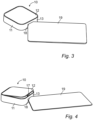
- the device 10 comprises a casing 11 and a cover 12.
- the casing 11 comprises walls 13 forming an enclosure.
- the casing 11 also comprises a bottom 14 connected to the walls 13 to form a box-shaped enclosure, a compartment or similar.
- the cover 12 is a casing front cover or back cover, wherein the cover 12 e.g. is arranged as a bracket for mounting on a structure, such as a wall, ceiling, door frame, window frame or any other suitable supporting structure.
- the casing 11 is arranged for mounting on such a supporting surface, wherein the bottom 14, e.g. is arranged as a bracket or to be mounted on a separate bracket.
- the device 10 is attachable to the supporting structure by means of conventional fastening means, such as screws or similar.
- the cover 12 is releasably connectable to the casing 11, so that the device 10 can be opened and closed.
- the device 10 is an intrusion alarm component, wherein the casing contains electronic parts, a detector, a battery compartment, an intrusion alarm gateway or similar.
- the device 10 is a battery compartment of a toy, tool or any other type of product having a casing 11 and a cover 12 for housing an object.
- the casing 11 and the cover 12 are, for example, made of plastic materials, which plastic materials optionally have inherent resilient flexible properties.
- the casing 11 and cover 12 are exclusively made of plastic materials.
- the casing 11 and cover 12 are made of metal or includes components of metal and/or plastic materials.
- the device 10 is box-shaped, wherein the bottom 14 and cover 12 are substantially flat and square or rectangular, optionally having rounded corners, and are arranged substantially in parallel to each other.
- the device 10 can be of a variety of shapes.
- the cover 12 can be inclined in relation to the bottom 14 and/or the walls 13.
- the cover 12 and/or the casing 11 can be arched.
- the cover 12 and/or bottom 14 can be, e.g. circular, oval, etc.
- an exterior surface of the cover 12 is flush with an end of the walls 13.
- the cover 12 is supported by a shoulder 15 on the walls 13 as illustrated in Fig. 2 by means of dashed lines.
- the end of the walls 13 extend beyond the exterior surface of the cover 12.
- the exterior surface of the cover 12 extends in a plane beyond the end of the walls 13.
- the casing 11 is arranged to form a chamber 16 within the walls 13, which chamber 16 can be closed by the cover 12 and is accessible by lifting or removing the cover 12 from the casing 11.
- the chamber 16 is defined by the interior of the casing 11 and cover 12 which are illustrated by means of dashed lines in Fig. 2 .
- the cover 12 is detachably attachable to the casing 11 by means of a latching mechanism 17.
- the latching mechanism 17 is arranged inside said chamber 16. Hence, the latching mechanism 17 is arranged inside the device 10. In Fig. 2 a part of said latching mechanism 17 is illustrated with dashed lines.
- the slot 18 is elongated and substantially rectangular, optionally with rounded corners or rounded end portions. Hence, the slot 18 has two substantially parallel long sides connecting two opposite ends. For example, the long sides are straight and regular.
- the slot 18 is a through slot 18 extending through the wall 13.
- the slot 18 extends from the chamber 16 to the exterior side of the casing 11.
- the slot 18 is arranged with a first dimension x and a second dimension y, wherein the second dimension y extends perpendicular to the first dimension x and in the same plane.
- the first dimension x substantially corresponds to the long sides of the slot 18.
- the first dimension x corresponds to a length of the slot 18.
- the second dimension y corresponds to a height of the slot 18.
- the first dimension x is 10-40 mm, 15-35 mm or 20-30 mm, wherein the second dimension y is 0.8-3 mm, 0.8-2 mm, 0.8-1.5 mm or 1-2 mm.
- the slot 18 is arranged for receiving a portion of a handheld object in the form of card 19, which is illustrated in Figs. 3 and 4 .
- the card 19 is a common plastic card used for ATM cards, payment cards, debit cards, bank cards, ID cards, driver licences, membership cards, public transport cards and many other applications, which many people carry in their wallet, purse, handbag, pocket or similar.
- the card 19 has flat, level, opposite and parallel main surfaces.
- the card 19 is rectangular, optionally with rounded corners, has a length of 60-100 mm or 80-90 mm, and a width of 40-60 mm or 50-55 mm.
- the thickness of the card 19 is, e.g. 0.5-1.5 mm or 0.6-1 mm.
- the main surface of the card 19 is 85.6 x 53.98 mm, wherein a thickness is 0.76 mm.
- the corners of the card 19 are, e.g. rounded with a radius of 2.88 to 4.48 mm.
- the card 19 complies with the ISO standard ISO/IEC 7810 ID-1 (December 30, 2016).
- the slot 18 is arranged for receiving a corner portion of the card 19, so that said corner portion can be introduced into the chamber 16 for operating the latching mechanism 17 to open the cover 12.
- the latching mechanism comprises two interacting latching parts, herein referred to as a first latching part 20 and a second latching part 21.
- the first latching part 20 is connected to the casing 11, wherein the second latching part 21 is connected to the cover 12, so that the cover 12 is detachably attachable to the casing 11 by means of the first and second latching parts 20, 21.
- the first and second latching parts 20, 21 are arranged in the chamber 16, wherein the latching mechanism is accessible through the slot 18 by means of the card 19 for releasing the latching mechanism.
- the first and second latching parts 20, 21 extend in opposite directions towards each other to overlap and form the latching mechanism.
- the first and second latching parts 20, 21 extend in a plane parallel to the cover 12 when the casing 11 is closed by the cover 12, wherein the first latching part 20 is arranged between the second latching part 21 and the interior side of the cover 12.
- the first and second latching parts 20, 21 extend in a direction substantially perpendicular to the wall 13 having the slot 18.
- the second latching part 21 is suspended from the interior side of the cover 12, e.g. through a plate, arm or similar to form the required distance to the interior side of the cover 12.
- first and second latching parts 20, 21 is movable in relation to the other.
- first latching part 20 is movable.
- the first latching part 20 is connected to an actuating portion 22 for operating the latching mechanism.
- the actuating portion 22 extends inside the chamber 16 in a position to be engaged by the card 19 when inserted through the slot 18 in the casing wall 13 in an insert direction z as illustrated in Fig. 6 .
- the actuating portion 22 extends in a plane substantially perpendicular to the insert direction z.
- the actuating portion 22 extends substantially in parallel to the wall 13 having the slot 18.
- the actuating portion 22 is arranged behind the slot 18, in the insertion path of the card 19, so that the actuating portion 22 overlaps the slot 18, with or without a gap to the interior side of the wall 13 having the slot 18.
- the actuating portion 22 extends substantially perpendicular to the first latching part 20.
- the first latching part 20 and the actuating portion 22 are suspended from a structure 23 being spring biased towards the latched position by means of a spring (not illustrated).
- said structure 23 is spring biased in a direction corresponding to the direction of the first latching part 20 and towards the second latching part 21, i.e. generally perpendicular to the actuating portion 22 and towards the wall 13 having the slot 18.
- the actuating portion 22 is arranged a distance D between an exterior side of the casing wall 13 having the slot 18 and the actuating portion 22 when the device 10 is in the latched position.
- said distance D is less than 10 mm or less than 5 mm.
- said distance D substantially corresponds to the thickness of the wall 13, wherein the actuating portion 22 extends along the interior side of the wall 13 and optionally also engages it.
- the actuating portion 22 is arranged with a gap to the interior side of the wall 13 having the slot 18 as illustrated in Fig. 5 .
- the interior side of the cover 12 is provided with a protrusion 24.
- the protrusion 24 extends in a direction perpendicular to a plane of the cover 12.
- the protrusion 24 is arranged with a slanting surface 25, so that the protrusion is tapered in a direction away from the interior side of the cover 12.
- the first latching part 20 is connected to an engaging surface 26 for engaging the slanting surface 25 of the protrusion 24, which engaging surface 26 is illustrated with dashed lines and is described in more detail below.
- the engaging surface 26 is also inclined.
- the engaging surface 26 extends in a direction substantially in parallel to the slanting surface 25.
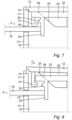
- the corner portion of the card 19 When the corner portion of the card 19 is inserted through the slot 18 in the insert direction z it engages the actuating portion 22 as illustrated in Fig. 6 . Then, when the card 19 is further pushed in the insert direction z it displaces the actuating portion 22 and the first latching part 20 to disengage the first latching part 20 from the second latching part 21 as illustrated in Fig. 7 , wherein the latching mechanism is released and the cover 12 can be removed from the casing 11. Hence, the first latching part 20 is displaced in the insert direction z of the card 19 away from the slot 18 to be released from the second latching part 21. The displacement of the first latching part 20 is made against the spring action biasing the first latching part 20 towards the second latching part 21 and the latched position.
- the engaging surface 26 is arranged with a gap to the slanting surface 25, which gap corresponds to or is larger than the overlap between the first and second latching parts 20, 21 and hence, the distance required to displace the first latching part 20 to disengage it from the second latching part 21.
- the latching mechanism and the operation thereof by means of the card 19 is illustrated more in detail according to one alternative embodiment.
- the second latching part 21 is connected to the cover 12 and is displaceable for unlatching the latching mechanism.
- the first latching part 20 is connected to the casing 11 and is projecting from the interior side of the wall 13 having the slot 18.
- the first latching part 20 is arranged between the free end of the wall 13 and the slot 18, i.e. between the slot 18 and the cover 12 when the cover 12 is connected to the casing 11.
- the first latching part 20 extends in a direction along the insert direction z of the card 19 and, e.g. in parallel to the cover 12 and perpendicular to the wall 13.
- the second latching part 21 is suspended from the interior side of the cover 12 by means of a resiliently flexible portion 27, such as a plate, arm or similar.
- the first latching part 20 is arranged between the interior side of the cover 12 and the second latching part 21, so that the cover 12 can be latched to the casing 11.
- the second latching part 21 is biased to engage the first latching part 20 by means of the inherent resilient flexible properties of the flexible portion 27, which is illustrated in Fig. 9 .
- the second latching part 21 includes the actuating portion 22 for operating the latching mechanism by means of the card 19.
- the actuating portion 22 is arranged in a level corresponding to the slot 18 and the path of insertion of the card 19 through the slot 18.
- the actuating portion 22 is formed with the slanting surface 25.
- the actuating portion 22 slides against the card 19 and pushes the cover 12 away from the casing 11 when the second latching part 21 is disengaged from the first latching part 20 as illustrated by means of the arrow A in Fig. 11 .
- the resilient properties of the flexible portion 27 biases the second latching part 21 in a direction back towards the wall 13 having the slot 18, which causes the slanting surface 25 to engage and push against the first latching part 20 to further force the cover 12 away from the casing 11 in the direction A, which is illustrated in Fig. 12 .
- the slanting surface 25 slides against the first latching part 20 and pushes the cover 12 open by the resilient flexible properties of the flexible portion 27.
- the first latching part 20 is formed with an inclined surface 28 for interaction with the slanting surface 25 to further improve the sliding operation between the first and second latching parts 20, 21 after unlatching.
- the slot 18 is arranged for receiving only the corner portion of the card 19 to a depth of maximum around 20 mm.
- the dimension x of the slot is less than 45 mm.
- the slot 18 is arranged for receiving only the corner portion of the card 19 to a depth of maximum around 10 mm.
- the dimension x of the slot is less than 25 mm.
- the slot 18 is arranged for receiving only the corner portion of the card 19 to a depth of maximum around 5 mm.
- the dimension x of the slot is less than 15 mm.
Landscapes
- Engineering & Computer Science (AREA)
- Mechanical Engineering (AREA)
- Casings For Electric Apparatus (AREA)
- Telephone Set Structure (AREA)
- Closures For Containers (AREA)
- Coupling Device And Connection With Printed Circuit (AREA)
Claims (12)
- Gerät (10), umfassend ein Gehäuse (11) und eine Abdeckung (12), wobei das Gehäuse (11) einen Boden (14) und Wände (13) umfasst, die eine innere Kammer (16) bilden, wobei die Abdeckung (12) lösbar mit dem Gehäuse (11) mittels eines Verriegelungsmechanismus (17) verbunden ist, der erste und zweite zusammenwirkende Verriegelungsteile (20, 21) aufweist, wobei mindestens eines der genannten Verriegelungsteile (20, 21) im Verhältnis zum anderen verschiebbar ist, und wobei eine der genannten Gehäusewände (13) mit einem durchgehenden Schlitz (18) zum Empfangen eines Abschnitts eines tragbaren Gegenstands zum Betätigen des verschiebbaren Verriegelungsteils (20, 21) gebildet ist,
gekennzeichnet dadurch, dassder genannte Schlitz (18) mit einer ersten Abmessung (x) und einer zweiten Abmessung (y) angeordnet ist, die zum Empfangen eines Abschnitts eines tragbaren Gegenstands in Form einer rechteckigen Kunststoffkarte (19) in einer Einführrichtung (z) durch den Schlitz (18) angepasst sind, undeines der genannten ersten und zweiten Verriegelungsteile (20, 21) mindestens teilweise in der Einführrichtung (z) verschiebbar ist und einen Betätigungsabschnitt (22) umfasst, der sich zum Ineingriffnehmen in einen Eckabschnitt der genannten rechteckigen Karte (19) in die Kammer (16) erstreckt, wenn diese durch den Schlitz (18) eingeführt wird, um den Verriegelungsmechanismus zu lösen. - Gerät nach Anspruch 1, wobei das Gerät eine schräge Fläche (24) umfasst, um die Abdeckung (12) vom Gehäuse (11) wegzudrücken, wenn der Verriegelungsmechanismus gelöst wurde.
- Gerät nach Anspruch 2, wobei das verschiebbare Verriegelungsteil (20, 21) oder die Abdeckung (11) mit der schrägen Fläche (24) versehen ist.
- Gerät nach einem der vorhergehenden Ansprüche, wobei die erste Abmessung (x) des Schlitzes 10 bis 40 mm und die zweite Abmessung (y) des Schlitzes 0,8 bis 3 mm beträgt.
- Gerät nach einem der vorhergehenden Ansprüche, wobei der Schlitz (18) zum Empfangen eines Eckabschnitts der genannten Karte (19) angeordnet ist, wobei die genannte Karte (19) eine Größe von 85,6 x 53,98 mm, eine Dicke von 0,76 mm und abgerundete Ecken mit einem Radius von 2,88 bis 3,48 mm aufweist.
- Gerät nach einem der vorhergehenden Ansprüche, wobei ein Abstand (D) zwischen einer Außenseite der Gehäusewand (13), die den Schlitz (18) aufweist, und dem Betätigungsabschnitt (22) weniger als 10 mm beträgt.
- Einbruchmeldekomponente, umfassend ein Gerät (10) nach einem der vorhergehenden Ansprüche und einen Detektor und/oder einen Prozessor und/oder ein drahtloses Kommunikationsmittel und/oder eine Batterie.
- Verfahren zum Lösen einer Abdeckung (12) von einem Gehäuse (11), wobei die Abdeckung (12) lösbar mit dem Gehäuse (11) mittels eines Verriegelungsmechanismus verbunden ist, der zusammenwirkende Verriegelungsteile (20, 21) aufweist, die in einer inneren Kammer (16) des Gehäuses (11) angeordnet sind, und wobei mindestens eines dieser Verriegelungsteile (20, 21) verschiebbar ist, wobei das genannte Verfahren die folgenden Schritte umfasst:a) Einführen eines Eckabschnitts eines tragbaren Gegenstands in Form einer rechteckigen Kunststoffkarte (19) in einer Einführrichtung (z) in einen Schlitz (18) in einer Wand (13) des Gehäuses (11),b) Bringen des genannten Eckabschnitts der rechteckigen Karte (19) zum Ineingriffnehmen eines Betätigungsabschnitts (22) des verschiebbaren Verriegelungsteils (20, 21) des Verriegelungsmechanismus,c) Verschieben des verschiebbaren Verriegelungsteils (20, 21) in der Einführrichtung (z), um es von dem anderen Verriegelungsteil (20, 21) durch weiteres Hineindrücken der rechteckigen Karte (19) in den Schlitz (18) und in die Kammer (16) freizugeben und dadurch die Abdeckung (12) von dem Gehäuse (11) zu lösen.
- Verfahren nach Anspruch 8, umfassend den Schritt, nach Schritt c) die Abdeckung (12) mittels einer schrägen Fläche (25) des Geräts vom Gehäuse (12) wegzudrücken.
- Verfahren nach Anspruch 9, umfassend die Schritte zum Bringen der Karte (19) zum Ineingriffnehmen einer schrägen Fläche (25) des verschiebbaren Verriegelungsteils (21) und durch Drücken auf die genannte schräge Fläche (25) mittels der Karte (19) zum Wegdrücken der Abdeckung (12) vom Gehäuse (12).
- Verfahren nach Anspruch 9 oder 10, umfassend die Schritte zum noch weiteren Einführen der Karte (19) in den Schlitz (18) und in die Kammer (16), und durch genanntes weiteres Einführen der Karte (19) das Wegdrücken der Abdeckung (12) vom Gehäuse (12) mittels der schrägen Fläche (25) des Geräts.
- Verfahren nach Anspruch 11, umfassend den Schritt zum Bringen des verschiebbaren Verriegelungsteils (20) zum Gleiten gegen einen inneren Vorsprung (24) der Abdeckung (12) und dadurch zum Wegdrücken der Abdeckung (12) vom Gehäuse (11) mittels der schrägen Fläche (25).
Priority Applications (5)
| Application Number | Priority Date | Filing Date | Title |
|---|---|---|---|
| PL16207583.2T PL3342963T3 (pl) | 2016-12-30 | 2016-12-30 | Urządzenie zawierające obudowę i pokrywę połączoną z obudową przy użyciu mechanizmu zatrzaskowego oraz sposób zwalniania pokrywy z obudowy |
| ES16207583T ES3039133T3 (en) | 2016-12-30 | 2016-12-30 | A device comprising a casing and a cover releasably connected to the casing by a latching mechanism, and a method for releasing a cover from a casing |
| EP16207583.2A EP3342963B1 (de) | 2016-12-30 | 2016-12-30 | Vorrichtung mit einem gehäuse und einer abdeckung, die lösbar mit dem gehäuse durch einen verriegelungsmechanismus verbunden ist, und verfahren zum lösen einer abdeckung aus einem gehäuse |
| PCT/EP2017/083805 WO2018122063A1 (en) | 2016-12-30 | 2017-12-20 | A device comprising a casing and a cover releasably connected to the casing by a latching mechanism, and a method for releasing a cover from a casing |
| BR112019013506-5A BR112019013506B1 (pt) | 2016-12-30 | 2017-12-20 | Dispositivo que compreende um invólucro e uma cobertura conectada de modo liberável ao invólucro por um mecanismo de travamento e um método para liberar uma cobertura de um invólucro |
Applications Claiming Priority (1)
| Application Number | Priority Date | Filing Date | Title |
|---|---|---|---|
| EP16207583.2A EP3342963B1 (de) | 2016-12-30 | 2016-12-30 | Vorrichtung mit einem gehäuse und einer abdeckung, die lösbar mit dem gehäuse durch einen verriegelungsmechanismus verbunden ist, und verfahren zum lösen einer abdeckung aus einem gehäuse |
Publications (3)
| Publication Number | Publication Date |
|---|---|
| EP3342963A1 EP3342963A1 (de) | 2018-07-04 |
| EP3342963B1 true EP3342963B1 (de) | 2025-08-13 |
| EP3342963C0 EP3342963C0 (de) | 2025-08-13 |
Family
ID=57794089
Family Applications (1)
| Application Number | Title | Priority Date | Filing Date |
|---|---|---|---|
| EP16207583.2A Active EP3342963B1 (de) | 2016-12-30 | 2016-12-30 | Vorrichtung mit einem gehäuse und einer abdeckung, die lösbar mit dem gehäuse durch einen verriegelungsmechanismus verbunden ist, und verfahren zum lösen einer abdeckung aus einem gehäuse |
Country Status (5)
| Country | Link |
|---|---|
| EP (1) | EP3342963B1 (de) |
| BR (1) | BR112019013506B1 (de) |
| ES (1) | ES3039133T3 (de) |
| PL (1) | PL3342963T3 (de) |
| WO (1) | WO2018122063A1 (de) |
Citations (2)
| Publication number | Priority date | Publication date | Assignee | Title |
|---|---|---|---|---|
| FR2748000A1 (fr) * | 1996-04-25 | 1997-10-31 | Jamont N V Public Limited Comp | Dispositif de verrouillage pour un boitier de distributeur |
| US6564998B1 (en) * | 2000-01-25 | 2003-05-20 | Hewlett-Packard Development Company | Card enabled latch for a portable computer |
Family Cites Families (4)
| Publication number | Priority date | Publication date | Assignee | Title |
|---|---|---|---|---|
| US4409806A (en) * | 1981-05-12 | 1983-10-18 | Herman Miller, Inc. | Locking system using codable magnetic cards |
| US5484175A (en) * | 1994-01-28 | 1996-01-16 | Maytag Corporation | Cabinet lock and method for using same |
| US20080136192A1 (en) * | 2006-12-07 | 2008-06-12 | Inventec Corporation | Lid body anchor system |
| CN101752524B (zh) * | 2008-12-01 | 2013-04-24 | 深圳富泰宏精密工业有限公司 | 电池盖卡锁结构 |
-
2016
- 2016-12-30 EP EP16207583.2A patent/EP3342963B1/de active Active
- 2016-12-30 ES ES16207583T patent/ES3039133T3/es active Active
- 2016-12-30 PL PL16207583.2T patent/PL3342963T3/pl unknown
-
2017
- 2017-12-20 BR BR112019013506-5A patent/BR112019013506B1/pt active IP Right Grant
- 2017-12-20 WO PCT/EP2017/083805 patent/WO2018122063A1/en not_active Ceased
Patent Citations (2)
| Publication number | Priority date | Publication date | Assignee | Title |
|---|---|---|---|---|
| FR2748000A1 (fr) * | 1996-04-25 | 1997-10-31 | Jamont N V Public Limited Comp | Dispositif de verrouillage pour un boitier de distributeur |
| US6564998B1 (en) * | 2000-01-25 | 2003-05-20 | Hewlett-Packard Development Company | Card enabled latch for a portable computer |
Also Published As
| Publication number | Publication date |
|---|---|
| WO2018122063A1 (en) | 2018-07-05 |
| EP3342963A1 (de) | 2018-07-04 |
| BR112019013506A2 (pt) | 2020-01-07 |
| BR112019013506B1 (pt) | 2023-02-14 |
| ES3039133T3 (en) | 2025-10-17 |
| PL3342963T3 (pl) | 2025-12-22 |
| EP3342963C0 (de) | 2025-08-13 |
Similar Documents
| Publication | Publication Date | Title |
|---|---|---|
| US11842589B2 (en) | Lock | |
| KR101475861B1 (ko) | 랜 포트락장치 | |
| US9593523B1 (en) | System and method for preventing/mitigating theft from a container, such as a safe | |
| CN104731278A (zh) | 箱体 | |
| RU2004134335A (ru) | Устройство для защиты от кражи | |
| US20180010369A1 (en) | Rolling door lock | |
| US6374757B1 (en) | Credit card security device | |
| EP3342963B1 (de) | Vorrichtung mit einem gehäuse und einer abdeckung, die lösbar mit dem gehäuse durch einen verriegelungsmechanismus verbunden ist, und verfahren zum lösen einer abdeckung aus einem gehäuse | |
| KR101795210B1 (ko) | 도어 잠금 장치 및 이를 구비한 보관 장치 | |
| KR20230053882A (ko) | 전자기기의 포트 차단모듈 및 이를 포함하는 포트 차단장치 | |
| US12300924B2 (en) | Port blocking module for electronic device and port locking apparatus comprising same | |
| KR101412724B1 (ko) | Usb 포트 잠금장치 | |
| EP1224372A1 (de) | Öffner für einen magnetischen riegel in einer diebstahlschutzvorrichtung für kassetten | |
| WO2002013650A1 (en) | Security device | |
| EP2732116A1 (de) | Verbessertes diebstahlschutzgehäuse | |
| JP6298209B1 (ja) | 収容ボックスの施錠装置 | |
| KR100668277B1 (ko) | 도난방지용 안전금고 | |
| KR200282347Y1 (ko) | 도어핸들 | |
| JP3114083U (ja) | ノート型pc収納用キャビネット | |
| EP3022372B1 (de) | Elektronische schlösser, insbesondere für büromöbel | |
| JP2006016793A (ja) | 扉のこじ開け防止機構 | |
| JP2012041758A (ja) | 錠装置、並びに、当該錠装置を用いる現金収納庫及び現金取扱装置 | |
| CN108824974B (zh) | 一种钥匙定位装置 | |
| KR20190036768A (ko) | 방범 방충망용 잠금장치 | |
| JP2014047470A (ja) | 収納箱の蓋構造 |
Legal Events
| Date | Code | Title | Description |
|---|---|---|---|
| PUAI | Public reference made under article 153(3) epc to a published international application that has entered the european phase |
Free format text: ORIGINAL CODE: 0009012 |
|
| STAA | Information on the status of an ep patent application or granted ep patent |
Free format text: STATUS: THE APPLICATION HAS BEEN PUBLISHED |
|
| AK | Designated contracting states |
Kind code of ref document: A1 Designated state(s): AL AT BE BG CH CY CZ DE DK EE ES FI FR GB GR HR HU IE IS IT LI LT LU LV MC MK MT NL NO PL PT RO RS SE SI SK SM TR |
|
| AX | Request for extension of the european patent |
Extension state: BA ME |
|
| STAA | Information on the status of an ep patent application or granted ep patent |
Free format text: STATUS: REQUEST FOR EXAMINATION WAS MADE |
|
| 17P | Request for examination filed |
Effective date: 20181211 |
|
| RBV | Designated contracting states (corrected) |
Designated state(s): AL AT BE BG CH CY CZ DE DK EE ES FI FR GB GR HR HU IE IS IT LI LT LU LV MC MK MT NL NO PL PT RO RS SE SI SK SM TR |
|
| 111Z | Information provided on other rights and legal means of execution |
Free format text: AL AT BE BG CH CY CZ DE DK EE ES FI FR GB GR HR HU IE IS IT LT LU LV MC MK MT NL NO PL PT RO RS SE SI SK SM TR Effective date: 20200720 |
|
| STAA | Information on the status of an ep patent application or granted ep patent |
Free format text: STATUS: EXAMINATION IS IN PROGRESS |
|
| 17Q | First examination report despatched |
Effective date: 20230530 |
|
| REG | Reference to a national code |
Ref country code: DE Ref legal event code: R079 Free format text: PREVIOUS MAIN CLASS: E05B0065520000 Ipc: E05C0019060000 Ref document number: 602016092646 Country of ref document: DE |
|
| GRAP | Despatch of communication of intention to grant a patent |
Free format text: ORIGINAL CODE: EPIDOSNIGR1 |
|
| STAA | Information on the status of an ep patent application or granted ep patent |
Free format text: STATUS: GRANT OF PATENT IS INTENDED |
|
| RIC1 | Information provided on ipc code assigned before grant |
Ipc: E05B 35/00 20060101ALN20241230BHEP Ipc: E05B 65/00 20060101ALI20241230BHEP Ipc: E05B 65/52 20060101ALI20241230BHEP Ipc: E05C 19/06 20060101AFI20241230BHEP |
|
| INTG | Intention to grant announced |
Effective date: 20250122 |
|
| GRAS | Grant fee paid |
Free format text: ORIGINAL CODE: EPIDOSNIGR3 |
|
| GRAA | (expected) grant |
Free format text: ORIGINAL CODE: 0009210 |
|
| STAA | Information on the status of an ep patent application or granted ep patent |
Free format text: STATUS: THE PATENT HAS BEEN GRANTED |
|
| AK | Designated contracting states |
Kind code of ref document: B1 Designated state(s): AL AT BE BG CH CY CZ DE DK EE ES FI FR GB GR HR HU IE IS IT LI LT LU LV MC MK MT NL NO PL PT RO RS SE SI SK SM TR |
|
| REG | Reference to a national code |
Ref country code: GB Ref legal event code: FG4D |
|
| REG | Reference to a national code |
Ref country code: CH Ref legal event code: EP |
|
| PUAC | Information related to the publication of a b1 document modified or deleted |
Free format text: ORIGINAL CODE: 0009299EPPU |
|
| STAA | Information on the status of an ep patent application or granted ep patent |
Free format text: STATUS: GRANT OF PATENT IS INTENDED |
|
| REG | Reference to a national code |
Ref country code: DE Ref legal event code: R096 Ref document number: 602016092646 Country of ref document: DE |
|
| GRAA | (expected) grant |
Free format text: ORIGINAL CODE: 0009210 |
|
| STAA | Information on the status of an ep patent application or granted ep patent |
Free format text: STATUS: THE PATENT HAS BEEN GRANTED |
|
| REG | Reference to a national code |
Ref country code: CH Ref legal event code: EP Ref country code: CH Ref legal event code: PK Free format text: DIE ERTEILUNG WURDE VOM EPA WIDERRUFEN. |
|
| REG | Reference to a national code |
Ref country code: IE Ref legal event code: FG4D |
|
| DB1 | Publication of patent cancelled |
Effective date: 20250704 |
|
| AK | Designated contracting states |
Kind code of ref document: B1 Designated state(s): AL AT BE BG CH CY CZ DE DK EE ES FI FR GB GR HR HU IE IS IT LI LT LU LV MC MK MT NL NO PL PT RO RS SE SI SK SM TR |
|
| REG | Reference to a national code |
Ref country code: CH Ref legal event code: EP |
|
| REG | Reference to a national code |
Ref country code: DE Ref legal event code: R107 Ref document number: 602016092646 Country of ref document: DE |
|
| REG | Reference to a national code |
Ref country code: DE Ref legal event code: R096 Ref document number: 602016092646 Country of ref document: DE |
|
| PG25 | Lapsed in a contracting state [announced via postgrant information from national office to epo] |
Ref country code: GR Free format text: LAPSE BECAUSE OF FAILURE TO SUBMIT A TRANSLATION OF THE DESCRIPTION OR TO PAY THE FEE WITHIN THE PRESCRIBED TIME-LIMIT Effective date: 20250926 |
|
| U01 | Request for unitary effect filed |
Effective date: 20250911 |
|
| REG | Reference to a national code |
Ref country code: ES Ref legal event code: FG2A Ref document number: 3039133 Country of ref document: ES Kind code of ref document: T3 Effective date: 20251017 |
|
| U07 | Unitary effect registered |
Designated state(s): AT BE BG DE DK EE FI FR IT LT LU LV MT NL PT RO SE SI Effective date: 20250918 |
|
| PG25 | Lapsed in a contracting state [announced via postgrant information from national office to epo] |
Ref country code: IS Free format text: LAPSE BECAUSE OF FAILURE TO SUBMIT A TRANSLATION OF THE DESCRIPTION OR TO PAY THE FEE WITHIN THE PRESCRIBED TIME-LIMIT Effective date: 20251025 |
|
| PGFP | Annual fee paid to national office [announced via postgrant information from national office to epo] |
Ref country code: GB Payment date: 20251229 Year of fee payment: 10 |
|
| PGFP | Annual fee paid to national office [announced via postgrant information from national office to epo] |
Ref country code: NO Payment date: 20251231 Year of fee payment: 10 |
|
| PG25 | Lapsed in a contracting state [announced via postgrant information from national office to epo] |
Ref country code: HR Free format text: LAPSE BECAUSE OF FAILURE TO SUBMIT A TRANSLATION OF THE DESCRIPTION OR TO PAY THE FEE WITHIN THE PRESCRIBED TIME-LIMIT Effective date: 20250813 |
|
| PGFP | Annual fee paid to national office [announced via postgrant information from national office to epo] |
Ref country code: IE Payment date: 20251229 Year of fee payment: 10 |
|
| PGFP | Annual fee paid to national office [announced via postgrant information from national office to epo] |
Ref country code: PL Payment date: 20251202 Year of fee payment: 10 |
|
| PG25 | Lapsed in a contracting state [announced via postgrant information from national office to epo] |
Ref country code: RS Free format text: LAPSE BECAUSE OF FAILURE TO SUBMIT A TRANSLATION OF THE DESCRIPTION OR TO PAY THE FEE WITHIN THE PRESCRIBED TIME-LIMIT Effective date: 20251113 |
|
| U20 | Renewal fee for the european patent with unitary effect paid |
Year of fee payment: 10 Effective date: 20251229 |