EP3342935A2 - Bagger - Google Patents
Bagger Download PDFInfo
- Publication number
- EP3342935A2 EP3342935A2 EP17203823.4A EP17203823A EP3342935A2 EP 3342935 A2 EP3342935 A2 EP 3342935A2 EP 17203823 A EP17203823 A EP 17203823A EP 3342935 A2 EP3342935 A2 EP 3342935A2
- Authority
- EP
- European Patent Office
- Prior art keywords
- boom
- excavator
- force
- force transfer
- flexible link
- Prior art date
- Legal status (The legal status is an assumption and is not a legal conclusion. Google has not performed a legal analysis and makes no representation as to the accuracy of the status listed.)
- Withdrawn
Links
Images












Classifications
-
- E—FIXED CONSTRUCTIONS
- E02—HYDRAULIC ENGINEERING; FOUNDATIONS; SOIL SHIFTING
- E02F—DREDGING; SOIL-SHIFTING
- E02F3/00—Dredgers; Soil-shifting machines
- E02F3/04—Dredgers; Soil-shifting machines mechanically-driven
- E02F3/28—Dredgers; Soil-shifting machines mechanically-driven with digging tools mounted on a dipper- or bucket-arm, i.e. there is either one arm or a pair of arms, e.g. dippers, buckets
- E02F3/30—Dredgers; Soil-shifting machines mechanically-driven with digging tools mounted on a dipper- or bucket-arm, i.e. there is either one arm or a pair of arms, e.g. dippers, buckets with a dipper-arm pivoted on a cantilever beam, i.e. boom
-
- E—FIXED CONSTRUCTIONS
- E02—HYDRAULIC ENGINEERING; FOUNDATIONS; SOIL SHIFTING
- E02F—DREDGING; SOIL-SHIFTING
- E02F3/00—Dredgers; Soil-shifting machines
- E02F3/04—Dredgers; Soil-shifting machines mechanically-driven
- E02F3/28—Dredgers; Soil-shifting machines mechanically-driven with digging tools mounted on a dipper- or bucket-arm, i.e. there is either one arm or a pair of arms, e.g. dippers, buckets
- E02F3/36—Component parts
- E02F3/38—Cantilever beams, i.e. booms;, e.g. manufacturing processes, forms, geometry or materials used for booms; Dipper-arms, e.g. manufacturing processes, forms, geometry or materials used for dipper-arms; Bucket-arms
- E02F3/382—Connections to the frame; Supports for booms or arms
-
- E—FIXED CONSTRUCTIONS
- E02—HYDRAULIC ENGINEERING; FOUNDATIONS; SOIL SHIFTING
- E02F—DREDGING; SOIL-SHIFTING
- E02F3/00—Dredgers; Soil-shifting machines
- E02F3/04—Dredgers; Soil-shifting machines mechanically-driven
- E02F3/28—Dredgers; Soil-shifting machines mechanically-driven with digging tools mounted on a dipper- or bucket-arm, i.e. there is either one arm or a pair of arms, e.g. dippers, buckets
- E02F3/36—Component parts
-
- E—FIXED CONSTRUCTIONS
- E02—HYDRAULIC ENGINEERING; FOUNDATIONS; SOIL SHIFTING
- E02F—DREDGING; SOIL-SHIFTING
- E02F3/00—Dredgers; Soil-shifting machines
- E02F3/04—Dredgers; Soil-shifting machines mechanically-driven
- E02F3/28—Dredgers; Soil-shifting machines mechanically-driven with digging tools mounted on a dipper- or bucket-arm, i.e. there is either one arm or a pair of arms, e.g. dippers, buckets
- E02F3/36—Component parts
- E02F3/38—Cantilever beams, i.e. booms;, e.g. manufacturing processes, forms, geometry or materials used for booms; Dipper-arms, e.g. manufacturing processes, forms, geometry or materials used for dipper-arms; Bucket-arms
-
- E—FIXED CONSTRUCTIONS
- E02—HYDRAULIC ENGINEERING; FOUNDATIONS; SOIL SHIFTING
- E02F—DREDGING; SOIL-SHIFTING
- E02F9/00—Component parts of dredgers or soil-shifting machines, not restricted to one of the kinds covered by groups E02F3/00 - E02F7/00
- E02F9/14—Booms only for booms with cable suspension arrangements; Cable suspensions
-
- E—FIXED CONSTRUCTIONS
- E02—HYDRAULIC ENGINEERING; FOUNDATIONS; SOIL SHIFTING
- E02F—DREDGING; SOIL-SHIFTING
- E02F9/00—Component parts of dredgers or soil-shifting machines, not restricted to one of the kinds covered by groups E02F3/00 - E02F7/00
- E02F9/18—Counterweights
-
- E—FIXED CONSTRUCTIONS
- E02—HYDRAULIC ENGINEERING; FOUNDATIONS; SOIL SHIFTING
- E02F—DREDGING; SOIL-SHIFTING
- E02F9/00—Component parts of dredgers or soil-shifting machines, not restricted to one of the kinds covered by groups E02F3/00 - E02F7/00
- E02F9/20—Drives; Control devices
- E02F9/22—Hydraulic or pneumatic drives
- E02F9/2217—Hydraulic or pneumatic drives with energy recovery arrangements, e.g. using accumulators, flywheels
-
- E—FIXED CONSTRUCTIONS
- E02—HYDRAULIC ENGINEERING; FOUNDATIONS; SOIL SHIFTING
- E02F—DREDGING; SOIL-SHIFTING
- E02F3/00—Dredgers; Soil-shifting machines
- E02F3/04—Dredgers; Soil-shifting machines mechanically-driven
- E02F3/28—Dredgers; Soil-shifting machines mechanically-driven with digging tools mounted on a dipper- or bucket-arm, i.e. there is either one arm or a pair of arms, e.g. dippers, buckets
- E02F3/30—Dredgers; Soil-shifting machines mechanically-driven with digging tools mounted on a dipper- or bucket-arm, i.e. there is either one arm or a pair of arms, e.g. dippers, buckets with a dipper-arm pivoted on a cantilever beam, i.e. boom
- E02F3/32—Dredgers; Soil-shifting machines mechanically-driven with digging tools mounted on a dipper- or bucket-arm, i.e. there is either one arm or a pair of arms, e.g. dippers, buckets with a dipper-arm pivoted on a cantilever beam, i.e. boom working downwardly and towards the machine, e.g. with backhoes
Definitions
- the technical field relates to an excavator comprising a balancing mechanism.
- Excavators also called diggers, are widely used in the market e.g. for digging and material handling. Such excavators typically comprise a boom, a bucket arm, a bucket and a cab on a rotating platform which is supported by an undercarriage having tracks or wheels.
- Known excavators use hydraulic power for actuating the different elements of the excavator, in particular for moving the boom, the bucket arm and the bucket. Such configurations are, however, often inefficient and expensive.
- an excavator comprising an articulated boom and a balancing mechanism.
- the balancing mechanism at least partially assists a movement of the boom from a lower position to an upper position by applying a pulling force on the boom. Accordingly, the lifiting operation of the excavator comprising the above described articulated boom in connection with the balancing mechanism is more efficient compared to systems which do not comprise such an at least partial assistance of a movement of the boom from a lower position to an upper position.
- a boom in the context of the present application may comprise multiple links and may comprise an attachment portion to which attachments like a bucket, a breaker, grapple or auger may be attached.
- the term boom may also refer to a main arm of an excavator only, that is to say to the arm of a link system which is directly coupled to a platform which also carries an operator's cab.
- a bucket arm may be attached to such a boom.
- articulated may include any connection allowing a defined movement from a lower position to an upper position.
- the boom may be articulated in that it is hingedly held, e.g. hingedly coupled to a platform of an excavator.
- the balancing mechanism at least partially assists a movement of the boom from a lower position to an upper position which is done by applying an assistive pulling force on the boom.
- the term "at least partially assisting” may include configurations in which the movement is fully assisted from the beginning to the end and configurations in which an assistance is provided only provided in certain ranges or points of the movement of the boom, e.g. at the beginning of the movement of the boom.
- any kind of application of a pulling force assisting the boom in moving from the lower to the upper position can be regarded as "partially assisting”.
- the balancing mechanism comprises a balancing member for generating an assisting force and a force transfer mechanism indirectly and force-transmittingly coupling the balancing member with the boom.
- the balancing member By coupling the balancing member with the boom in this way, the variability of the overall construction of the excavator is improved as the balancing member can be placed at any suitable position of the excavator, e.g. on the opposite side of a coupling position of a platform or top frame of an excavator where the boom is coupled to the same.
- the balancing member may be arranged at a distance from the boom, e.g. in a rear portion of an excavator.
- "indirectly and force-transmittingly coupling” means that there is no direct attachment of the balancing member on the boom as would be the case where an element of the balancing member is directly coupled to the boom by means of a pivot pin.
- a force generated by the balancing member is transferred to the boom by at least one intermediate member which does not have an additional function besides transferring the force from the balancing member to the boom.
- the force transfer mechanism comprises a flexible link, preferably a wire rope or chain.
- the flexible link By using a flexible link, it is possible to transfer forces on suitable paths allowing for a greater freedom of design. Furthermore, using a flexible link is optimum for transferring tensile forces while allowing lightweight constructions. Moreover, such force transfer mechanisms are easy to maintain.
- the flexible link may be deflected by means of one or more pulleys provided in the force transfer mechanism.
- the balancing member is coupled to the flexible link at a coupling portion of the flexible link, preferably in such a manner that a direction of a force generated by the balancing member is aligned or parallel with an extension direction of the flexible link in the coupling portion.
- a force generated by the balancing member may be linearly transferred to the flexible link which is beneficial as no forces a created on the balancing member in a direction which differs from the force generation direction. In this manner, the durability of the mechanism is enhanced.
- the force transfer mechanism comprises a transmission.
- a transmission is to be understood as a device or mechanism which is able to convert an input force to a different output force and thus having a transmission ratio different from one.
- a transmission may be realized as a constant or a variable transmission which means that the transmission may comprise a fixed transmission ratio or a variable transmission ratio. Since the force transfer mechanism comprises a transmission, the force created by the balancing member can be converted to a suitable force needed for a specific configuration while keeping the size of the balancing member at an appropriate dimension. Thus, using a transmission allows for a more compact and cost-efficient configuration.
- the transmission comprises a cone-shaped pulley and the flexible link is guided around the cone-shaped pulley in an axially offset manner. In this way, a reliable and easy to manufacture transmission is provided.
- the flexible link e.g. a wire rope
- the flexible link can be guided around such a pulley in a helical manner.
- axially offset manner is to be understood in such a way that an initial contact between the flexible link and the cone-shaped pulley is made at a first portion of the pulley and a disengagement of the flexible link from the cone-shaped pulley is made at a second portion of the pulley wherein the first portion and the second portion are provided at different axial positions of the cone-shaped pulley.
- the pulley can have the shape of a truncated cone.
- the force transfer mechanism comprises a coupling device for transferring a force from the flexible link to the boom such that an assisting moment assisting said movement of the boom is generated on the boom.
- the coupling device may be any device which is able to transfer a force from the flexible link to the boom such that an assisting moment is generated on the boom.
- the coupling device may comprise a disc shape and can be mounted to the boom integrally movable with the same.
- the flexible link may be mounted to and guided on a peripheral edge surface. In this way, a simple and reliable coupling device is provided rendering the overall excavator more cost-efficient.
- the coupling device is structured such that a force introduced into the coupling device by the flexible link is transferred to the boom at a fixed ratio independent from the position of the boom. In this way, the force applied to the boom is constant over the entire movement of the boom.
- the coupling device is structured such that a force introduced into the coupling device by the flexible link is transferred to the boom with a varying ratio, the varying ratio changing according to the position of the boom. Accordingly, a varying transmission ratio can be provided which can be adapted to the position of the boom in the movement range of the boom and thus be adapted to a moment.
- the coupling device comprises a force transfer device fixedly coupled to the boom such that the force transfer device and the boom are integrally movable, wherein the force transfer device comprises a peripheral surface for guiding the flexible link at a predetermined distance from a hinge portion at which the boom is articulated, and wherein the flexible link is coupled to the force transfer device such that a portion of the flexible link contacts a predetermined section of the peripheral surface when the boom is in a lower position.
- the peripheral surface is at least partially curved and preferably at least partially comprises the shape of a circular arc.
- a center axis of the force transfer device is aligned with a rotational axis of the boom in the hinge portion.
- the balancing member is a counter weight.
- the balancing member is a pressure cylinder.
- the force transfer mechanism comprises rigid links.
- Fig.1 shows a side view of an excavator 1 according to an embodiment of the present disclosure.
- the excavator 1 comprises a platform 2, also called top frame, which is rotatably coupled to an undercarriage 3 having tracks 5.
- a boom 4 is hingedly mounted at a hinge portion 24, i.e. at a first end of the boom 4, and an operator's cab 40 is provided.
- the boom 4 is rotatable about a rotation axis A.
- a dipper 6, also called stick or bucket arm, is hingedly coupled to the boom 4.
- a bucket 7 is hingedly coupled to the dipper 6.
- the boom 4 is movable by means of a first hydraulic cylinder 50 supported on the platform 2 and coupled to the boom
- the dipper 6 is movable by means of a second hydraulic cylinder 52 supported on the boom and connected to the dipper
- the bucket is movable by means of a third hydraulic cylinder 54 supported on the dipper and coupled to the bucket 7.
- first cylinder 50 is shown in Fig. 1
- the hydraulic cylinder 50 exerts a pushing force on the boom 4 in order to move the same.
- a motor (not shown) is provided for generating power used for moving the excavator and for actuating the hydraulic cylinders 50, 52, 54.
- the excavator 1 further comprises a balancing mechanism 8 which is configured to apply a pulling force on the boom 4. In this way, less power has to be applied on the boom 4 by the first hydraulic cylinder 50 in order to move the boom 4 allowing to use smaller hydraulic cylinders.
- the response characteristics are enhanced because the force necessary for moving the boom 4 can be generated faster in the first hydraulic cylinder 50.
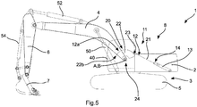
- the balancing mechanism 8 as shown in Fig. 2 comprises a balancing member 10 for generating an assisting force and a force transfer mechanism 11 for transferring the force generated by the balancing member 10 to the boom 4.
- the balancing member 10 is a pressure cylinder 13 comprising nitrogen as pressure gas and is mounted to the platform 2 at one end and coupled to the force transfer mechanism 11 at the other end.
- the general construction of the excavator as described so far also applies for all embodiments other than the one described with respect to Fig. 1 .
- the force transfer mechanism as shown in Fig. 1 comprises a flexible link 12 which in this embodiment is a wire rope 21.
- a chain (not shown) could also be used instead of the wire rope 21.
- the wire rope 21 is at one end coupled to the pressure cylinder 13 at a coupling portion 14 in such a manner that a direction of a force generated by the pressure cylinder 13 is aligned with an extension direction of the wire rope 21.
- the wire rope 21 is coupled to a coupling device 20 which is configured to transfer a force from the wire rope 21 to the boom 4 such that an assisting moment assisting the movement of the boom 4 is generated on said boom 4.
- the coupling device 20 is structured such that a force introduced into the coupling device 20 by the wire rope 21 is transferred to the boom 4 at a fixed ratio independent from the position of the boom 4.
- the coupling device 20 comprises a force transfer device 22 fixedly coupled to the boom 4 such that the force transfer device 22 and the boom are integrally movable.
- the force transfer device 22 can be welded to the boom 4 or may be fixedly attached by means of threaded bolts or screws.
- the force transfer device 22 comprises a peripheral surface 23 for guiding the wire rope 21 at a predetermined distance from hinge portion 24 at which the boom 4 is articulated.
- the peripheral surface 23 of the force transfer device 22 follows a circular path having its center on center axis A. Center axis A is aligned with rotational axis B of the boom 4 in the hinge portion 24.
- the wire rope 21 is coupled to the force transfer device 22 at a fixation portion 22b thereof, i.e. in Fig. 1 on the left side peripheral surface end of the force transfer device 22, such that a portion 12a of the wire rope 21 contacts a predetermined section of the peripheral surface 23 when the boom 4 is in the position as shown in Fig. 1 .
- This position of the boom as shown can also be referred to as lower position.
- the dimension of the portion 12a will increase whereas when the boom 4 is moved in the clockwise direction, the wire rope 21 will unwound from the force transfer device so that the dimension of the portion 12a will decrease. Since the peripheral surface follows a circular path about the hinge axis A, a force transferred on the force transfer device 22 is always converted into torque acting on the boom 4 with the same ratio. In other words, if the force generated by the pressure cylinder 13 is constant over the entire movement area of the boom 4, a corresponding constant torque will be generated on the boom 4.
- Fig. 2 shows a configuration of an excavator 1 which differs from the configuration as shown in Fig. 1 in that the pressure cylinder 13 is arranged inversely.
- the coupling portion 14 comprises a link 14a which allows a coupling of the wire rope 21 at a position which is laterally offset with respect to the pressure cylinder 13.
- the wire rope 13 extends along and parallel to the pressure cylinder 13.
- Fig. 3 shows a configuration of an excavator 1 which differs from the configuration as shown in Fig. 1 in that the pressure cylinder 13 is arranged inversely similar to the embodiment shown in Fig. 2 .
- the force transfer mechanism 11 comprises a deflection pulley 11a which deflects the wire rope 21, about 180° in the example as shown.
- the direction of a pulling force exerted on the pressure cylinder is independent from a dimension of the force transfer device 22.
- the pressure cylinder extends substantially horizontally and this will not change even if a differently shaped force transfer device 22 is used.
- Fig. 4A shows a configuration of an excavator 1 according to a further embodiment which differs from the configuration as shown in Fig. 3 in that the force transfer mechanism 11 comprises a transmission realized by a cone-shaped pulley 11b, i.e. a pulley shaped in the form of a truncated cone, instead of the deflection pulley 11a as shown in Fig. 3 .
- the transmission is generated by means of a diameter difference of between pulley surface portions where a contact of the wire rope 21 with the pulley is established or released.
- these pulley surface portions are provided on the left and right end of the conical surface of the cone-shaped pulley 11b as shown in Figs. 4B and 4C .
- the wire rope 21 coming from the pressure cylinder 13 makes contact with the surface of the cone-shaped pulley 11b on the left side in Fig. 4C , i.e. at a portion of the pulley having the greatest diameter.
- the wire rope 21 is then wound about the outer surface of the pulley multiple times and leaves the pulley surface at a portion having smallest diameter. In this way, the output force on the wire rope 21 is increased by the pulley.
- the cone-shaped pulley 11b provides a reliable and cost-efficient transmission.
- Fig. 5 shows a configuration of an excavator 1 according to a further embodiment which differs from the configuration as shown in Fig. 1 only in that the pressure cylinder 13 is coupled to a lower portion of the platform 2 so that a larger portion 12a of the wire rope 21 which can contact a predetermined section of the peripheral surface 23 is available. With this configuration, an assisting range is increased.
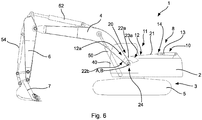
- Fig. 6 shows a configuration of an excavator 1 according to a further embodiment which differs from the configuration as shown in Fig. 1 only in the construction of the coupling device 20.
- the coupling device 20 is structured such that a force introduced into the coupling device 20 by the wire rope 21 is transferred to the boom 4 at a variable ratio dependent on the position of the boom 4.
- the coupling device 20 comprises a force transfer device 22a fixedly coupled to the boom 4 such that the force transfer device 22a and the boom 4 are integrally movable.
- the force transfer device 22a comprises a peripheral surface 23a which comprises a contour defined by a path extending about center axis A while a radial distance with respect to the axis A increases when following the path in clockwise direction in Fig. 5 .
- the force transfer device 22a is structured such that a force introduced into the force transfer device 22a by the wire rope 21 generates a maximum torque when the boom is rotated to the lowest position.
- the point at which force from the wire rope 21 is introduced into the force transfer device 22a moves towards axes A, B so that a distance for torque generation is reduced. Accordingly, the transmission ratio varies with the movement of the boom 4.
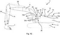
- Fig. 7 shows a configuration of an excavator 1 according to a further embodiment which differs from the configuration as shown in Fig. 6 only in that the force transfer mechanism 11 comprises a deflection pulley 11c which is arranged between the pressure cylinder 13 and the coupling device 20.
- the deflection pulley 11c By using the deflection pulley 11c, a force transferred via coupling portion 14 is always transferred in the same direction, which in the embodiment as shown is a substantially horizontal direction.
- Fig. 8 shows a configuration of an excavator 1 according to a further embodiment which differs from the configuration as shown in Fig. 7 only in that the force transfer mechanism 11 comprises a deflection pulley 11d which is configured like the cone-shaped pulley 11b as shown in Figs. 4A, 4B and 4C .
- deflection pulley 11d additionally comprises transmission capabilities as described above with respect to the embodiment as shown in Figs. 4A, 4B and 4C .
- Fig. 9 shows a configuration of an excavator 1 according to a further embodiment which differs from the configuration as shown in Fig. 2 only in that coupling device 20 is structured as described in connection with the embodiment as shown in Fig. 5 .
- Fig. 10 shows a configuration of an excavator 1 according to a further embodiment which differs from the configuration as shown in Fig. 7 in that the pressure cylinder is inversely arranged in a manner as described with respect to the embodiment as shown in Fig. 2 .
- Fig. 11 shows a configuration of an excavator 1 according to a further embodiment which differs from the configuration as shown in Fig. 3 only in that coupling device 20 is structured as described in connection with the embodiment as shown in Fig. 5 .
- Fig. 12 shows a configuration of an excavator 1 according to a further embodiment which differs from the configuration as shown in Fig. 8 only in that the pressure cylinder is inversely arranged in a manner as described with respect to the embodiment as shown in Fig. 2 .
- Fig. 13 shows a configuration of an excavator 1 according to a further embodiment which differs from the configuration as shown in Fig. 4 only in that coupling device 20 is structured as described in connection with the embodiment as shown in Fig. 6 .
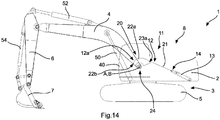
- Fig. 14 shows a configuration of an excavator 1 according to a further embodiment which differs from the configuration as shown in Fig. 5 only in that coupling device 20 is structured as described in connection with the embodiment as shown in Fig. 6 .
- Fig. 15 shows a configuration of an excavator 1 according to a further embodiment which differs from the configuration as shown in Fig. 7 only in that instead of coupling device 20 a link mechanism 60 is used for transferring a force introduced into the link mechanism 60 by the wire rope 21 is transferred to the boom 4 at a fixed ratio independent from the position of the boom 4.
- the link mechanism 60 comprises a rigid force transfer link 62 connected to the end of the wire rope 21 at a connecting portion 66 and hingedly coupled to the boom 4 at the other end thereof and a rigid guiding link 64 coupled to the connecting portion 66 between wire rope 21 and force transfer link 62 at one end and hingedly coupled to the platform 2 at the other end.
- Fig. 16 shows a configuration of an excavator 1 according to a further embodiment which differs from the configuration as shown in Fig. 8 only in that instead of coupling device 20 a link mechanism 60 according to the embodiment as shown in Fig. 15 is used.
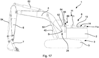
- Fig. 17 shows a configuration of an excavator 1 according to a further embodiment which differs from the configuration as shown in Fig. 3 only in that instead of coupling device 20 a link mechanism 60 according to the embodiment as shown in Fig. 15 is used.
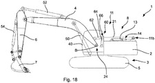
- Fig. 18 shows a configuration of an excavator 1 according to a further embodiment which differs from the configuration as shown in Figs. 4A, 4B and 4C only in that instead of coupling device 20 a link mechanism 60 according to the embodiment as shown in Fig. 15 is used.
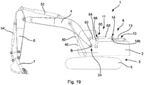
- Fig. 19 shows a configuration of an excavator 1 according to a further embodiment which differs from the configuration as shown in Fig. 15 in that the force transfer mechanism is entirely constructed from rigid links 14a, 62, 64, and 68.
- the wire rope 21 as well as the deflection pulley 11c are replaced by links 68 and 14a.
- link 14a reference is made to the above embodiments which also include this link 14a.
- Fig. 20 shows a configuration of an excavator 1 according to a further embodiment which differs from the configuration as shown in Fig. 19 in that the pressure cylinder is inversely arranged and exerts a pushing force.
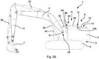
- Fig. 21 shows a configuration of an excavator 1 according to a further embodiment which differs from the configuration as shown in Fig. 15 in that the link mechanism 60 comprises a length adjustable hydraulic cylinder 70. By adjusting the length of the hydraulic cylinder 70 a transmission ratio of the force applied on the boom 4 by link 62 can be adjusted.
- Fig. 22 shows a configuration of an excavator 1 according to a further embodiment which differs from the configuration as shown in Fig. 16 in that the link mechanism 60 comprises a length adjustable hydraulic cylinder 70 as described with respect to the embodiment shown in Fig. 21 .
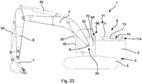
- Fig. 23 shows a configuration of an excavator 1 according to a further embodiment which differs from the configuration as shown in Fig. 17 in that the link mechanism 60 comprises a length adjustable hydraulic cylinder 70 as described with respect to the embodiment shown in Fig. 21 .
- Fig. 24 shows a configuration of an excavator 1 according to a further embodiment which differs from the configuration as shown in Fig. 18 in that the link mechanism 60 comprises a length adjustable hydraulic cylinder 70 as described with respect to the embodiment shown in Fig. 21 .
- Fig. 25 shows a configuration of an excavator 1 according to a further embodiment which differs from the configuration as shown in Fig. 19 in that the link mechanism 60 comprises a length adjustable hydraulic cylinder 70 as described with respect to the embodiment shown in Fig. 21 .
- buckets of different sizes can be used on the bucket arm.
- the load transfer mechanism 11 can be adapted to the bucket size or tool used in order to assist a movement of the boom in the upward direction in an optimum way.
- the force transfer device can be arranged releasably locked to the boom and can be exchanged with another force transfer device having a different shape and better suiting the tool or bucket size as mounted.
- a force transfer device having several different force transfer sections in a direction of the axis B and a force transfer changing mechanism being able to shift between the force transfer sections in order to adapt the force transfer device to the bucket size or load.
Landscapes
- Engineering & Computer Science (AREA)
- Mechanical Engineering (AREA)
- Mining & Mineral Resources (AREA)
- Civil Engineering (AREA)
- General Engineering & Computer Science (AREA)
- Structural Engineering (AREA)
- Earth Drilling (AREA)
Applications Claiming Priority (1)
| Application Number | Priority Date | Filing Date | Title |
|---|---|---|---|
| PCT/CN2016/112404 WO2018119678A1 (en) | 2016-12-27 | 2016-12-27 | Excavator |
Publications (2)
| Publication Number | Publication Date |
|---|---|
| EP3342935A2 true EP3342935A2 (de) | 2018-07-04 |
| EP3342935A3 EP3342935A3 (de) | 2018-12-05 |
Family
ID=60473416
Family Applications (1)
| Application Number | Title | Priority Date | Filing Date |
|---|---|---|---|
| EP17203823.4A Withdrawn EP3342935A3 (de) | 2016-12-27 | 2017-11-27 | Bagger |
Country Status (4)
| Country | Link |
|---|---|
| US (2) | US20180179727A1 (de) |
| EP (1) | EP3342935A3 (de) |
| CN (1) | CN108240004A (de) |
| WO (1) | WO2018119678A1 (de) |
Families Citing this family (9)
| Publication number | Priority date | Publication date | Assignee | Title |
|---|---|---|---|---|
| JP1593401S (de) * | 2016-11-30 | 2017-12-18 | ||
| WO2018119678A1 (en) | 2016-12-27 | 2018-07-05 | Guangxi Liugong Machinery Co., Ltd. | Excavator |
| WO2021035475A1 (en) * | 2019-08-26 | 2021-03-04 | Guangxi Liugong Machinery Co., Ltd. | Loader |
| DE102019130784A1 (de) * | 2019-11-14 | 2021-05-20 | Liebherr-Hydraulikbagger Gmbh | Arbeitsmaschine, insbesondere Materialumschlagsgerät mit einem Ausleger sowie Auslegerabspannung |
| CN112049177B (zh) * | 2020-09-07 | 2022-11-08 | 江苏师范大学 | 一种挖掘机动臂势能电动回收及再利用节能装置 |
| JP7737269B2 (ja) * | 2021-03-31 | 2025-09-10 | ナブテスコ株式会社 | 建設機械、駆動システム及び駆動装置 |
| CN113374022B (zh) * | 2021-04-26 | 2022-08-02 | 徐州纳维尔机械制造有限公司 | 基于弹簧组和变径滚筒的挖掘机动臂节能装置及工作方法 |
| CN114263227A (zh) * | 2022-02-07 | 2022-04-01 | 汪梦林 | 一种节能型挖掘机 |
| DE102023113844A1 (de) * | 2023-05-25 | 2024-11-28 | Menglin WANG | Eine energiesparende Aushubmaschine |
Family Cites Families (19)
| Publication number | Priority date | Publication date | Assignee | Title |
|---|---|---|---|---|
| US3392855A (en) * | 1966-04-04 | 1968-07-16 | Warner Swasey Co | Material handling machine |
| US3388819A (en) * | 1966-04-04 | 1968-06-18 | Warner Swasey Co | Material handling machine |
| US3856161A (en) * | 1973-11-02 | 1974-12-24 | Marion Power Shovel Co | Power shovel |
| US4046270A (en) * | 1974-06-06 | 1977-09-06 | Marion Power Shovel Company, Inc. | Power shovel and crowd system therefor |
| US4085854A (en) * | 1975-10-03 | 1978-04-25 | Marion Power Shovel Co., Inc. | Pitch stop assembly for power shovels |
| US4221531A (en) * | 1978-10-06 | 1980-09-09 | Dresser Industries, Inc. | Power shovel having improved front end assembly |
| EP0175390A1 (de) * | 1981-10-21 | 1986-03-26 | Priestman Brothers Limited | Erdbewegungsmaschine |
| JPS60168828A (ja) * | 1984-02-14 | 1985-09-02 | Handoothe- Kogyo Kk | 掘削機 |
| US4768762A (en) * | 1985-05-15 | 1988-09-06 | Lund Kurt O | Means and method to counterbalance the weight of a body |
| US6725584B2 (en) * | 2001-05-22 | 2004-04-27 | Jrb Company, Inc. | Quick connect/disconnect system for an arm of excavator or other machine |
| CN2668706Y (zh) * | 2004-04-29 | 2005-01-05 | 杨双来 | 新型挖掘机 |
| JP2008019680A (ja) * | 2006-07-14 | 2008-01-31 | Shin Caterpillar Mitsubishi Ltd | 作業機械用ブームの動作助力機構 |
| RO122787B1 (ro) * | 2006-07-24 | 2010-01-29 | Sorin Dinu | Dispozitiv de recuperare a energiei din operaţia de coborâre a braţului unui utilaj |
| JP5090148B2 (ja) * | 2007-12-11 | 2012-12-05 | 住友重機械工業株式会社 | 建設機械 |
| DE102008018451A1 (de) * | 2008-04-04 | 2010-02-04 | Thomas Sauer | Entlastungszug an Hydraulikbaggern |
| KR101248580B1 (ko) * | 2008-08-08 | 2013-03-28 | 볼보 컨스트럭션 이큅먼트 에이비 | 작업장치 보조 구동수단이 구비된 굴삭기 |
| CN203129205U (zh) * | 2013-04-08 | 2013-08-14 | 孙雷 | 动臂配重随动挖掘机 |
| AU2015200233B2 (en) * | 2014-01-21 | 2019-01-31 | Joy Global Surface Mining Inc | Controlling the operation of an industrial machine based on wire rope dead wraps |
| WO2018119678A1 (en) | 2016-12-27 | 2018-07-05 | Guangxi Liugong Machinery Co., Ltd. | Excavator |
-
2016
- 2016-12-27 WO PCT/CN2016/112404 patent/WO2018119678A1/en not_active Ceased
-
2017
- 2017-09-13 CN CN201710823245.8A patent/CN108240004A/zh active Pending
- 2017-11-06 US US15/804,811 patent/US20180179727A1/en not_active Abandoned
- 2017-11-27 EP EP17203823.4A patent/EP3342935A3/de not_active Withdrawn
-
2018
- 2018-12-13 US US16/218,891 patent/US10428490B2/en not_active Expired - Fee Related
Also Published As
| Publication number | Publication date |
|---|---|
| US10428490B2 (en) | 2019-10-01 |
| WO2018119678A1 (en) | 2018-07-05 |
| EP3342935A3 (de) | 2018-12-05 |
| US20190112780A1 (en) | 2019-04-18 |
| US20180179727A1 (en) | 2018-06-28 |
| CN108240004A (zh) | 2018-07-03 |
Similar Documents
| Publication | Publication Date | Title |
|---|---|---|
| US10428490B2 (en) | Excavator with rigid force transfer link | |
| EP2402513B1 (de) | Zweiarmige Baumaschine | |
| US4932832A (en) | Backhoe gripping attachment | |
| CN1946907B (zh) | 工程机械的作业装置 | |
| CN108867726A (zh) | 一种挖掘机 | |
| EP3574152B1 (de) | Auslegeranordnung | |
| CN113423896B (zh) | 用于促进器具在机器中的枢转移动的设备 | |
| US4494906A (en) | Earthmoving machine | |
| EP0287591B1 (de) | Ausleger für ein fahrzeug | |
| JP6581065B2 (ja) | 作業機械 | |
| CN107209532A (zh) | 致动器控制装置及作业车辆 | |
| EP1566488B1 (de) | Baggerauslegergelenkanordnung | |
| WO2018153934A1 (en) | Device for an excavator | |
| RU2804967C2 (ru) | Устройство для облегчения поворотного движения рабочего инструмента относительно плеча машины, рычажный механизм в сборе для управления рабочим инструментом относительно рамы машины и рабочая машина | |
| US11976436B2 (en) | Excavator thumb with structural support | |
| US7739813B2 (en) | Telescoping boom for excavating apparatus | |
| US11753790B2 (en) | Cross-support assembly extending between and connecting two generally parallel lifting arms of a working machine | |
| EP0175390A1 (de) | Erdbewegungsmaschine | |
| KR20220026418A (ko) | 건설기계의 작업장치 | |
| KR20220026421A (ko) | 건설기계의 작업장치 |
Legal Events
| Date | Code | Title | Description |
|---|---|---|---|
| PUAI | Public reference made under article 153(3) epc to a published international application that has entered the european phase |
Free format text: ORIGINAL CODE: 0009012 |
|
| STAA | Information on the status of an ep patent application or granted ep patent |
Free format text: STATUS: THE APPLICATION HAS BEEN PUBLISHED |
|
| AK | Designated contracting states |
Kind code of ref document: A2 Designated state(s): AL AT BE BG CH CY CZ DE DK EE ES FI FR GB GR HR HU IE IS IT LI LT LU LV MC MK MT NL NO PL PT RO RS SE SI SK SM TR |
|
| AX | Request for extension of the european patent |
Extension state: BA ME |
|
| PUAL | Search report despatched |
Free format text: ORIGINAL CODE: 0009013 |
|
| AK | Designated contracting states |
Kind code of ref document: A3 Designated state(s): AL AT BE BG CH CY CZ DE DK EE ES FI FR GB GR HR HU IE IS IT LI LT LU LV MC MK MT NL NO PL PT RO RS SE SI SK SM TR |
|
| AX | Request for extension of the european patent |
Extension state: BA ME |
|
| RIC1 | Information provided on ipc code assigned before grant |
Ipc: E02F 9/22 20060101ALI20181026BHEP Ipc: E02F 9/18 20060101ALI20181026BHEP Ipc: E02F 3/42 20060101ALI20181026BHEP Ipc: E02F 3/30 20060101AFI20181026BHEP |
|
| STAA | Information on the status of an ep patent application or granted ep patent |
Free format text: STATUS: REQUEST FOR EXAMINATION WAS MADE |
|
| 17P | Request for examination filed |
Effective date: 20190403 |
|
| RBV | Designated contracting states (corrected) |
Designated state(s): AL AT BE BG CH CY CZ DE DK EE ES FI FR GB GR HR HU IE IS IT LI LT LU LV MC MK MT NL NO PL PT RO RS SE SI SK SM TR |
|
| STAA | Information on the status of an ep patent application or granted ep patent |
Free format text: STATUS: EXAMINATION IS IN PROGRESS |
|
| 17Q | First examination report despatched |
Effective date: 20211206 |
|
| STAA | Information on the status of an ep patent application or granted ep patent |
Free format text: STATUS: THE APPLICATION IS DEEMED TO BE WITHDRAWN |
|
| 18D | Application deemed to be withdrawn |
Effective date: 20220420 |