EP3342670B1 - Procédé d'ajustement dynamique de la variation de commande de vitesse de véhicules autonomes - Google Patents
Procédé d'ajustement dynamique de la variation de commande de vitesse de véhicules autonomes Download PDFInfo
- Publication number
- EP3342670B1 EP3342670B1 EP17191258.7A EP17191258A EP3342670B1 EP 3342670 B1 EP3342670 B1 EP 3342670B1 EP 17191258 A EP17191258 A EP 17191258A EP 3342670 B1 EP3342670 B1 EP 3342670B1
- Authority
- EP
- European Patent Office
- Prior art keywords
- speed control
- cost
- control rate
- speed
- individual
- Prior art date
- Legal status (The legal status is an assumption and is not a legal conclusion. Google has not performed a legal analysis and makes no representation as to the accuracy of the status listed.)
- Active
Links
- 238000000034 method Methods 0.000 title claims description 40
- 230000006870 function Effects 0.000 claims description 89
- 238000012545 processing Methods 0.000 claims description 30
- 230000015654 memory Effects 0.000 claims description 18
- 230000008859 change Effects 0.000 claims description 11
- 230000008447 perception Effects 0.000 description 23
- 230000008569 process Effects 0.000 description 17
- 238000010586 diagram Methods 0.000 description 13
- 238000004891 communication Methods 0.000 description 11
- 230000001133 acceleration Effects 0.000 description 10
- 238000010801 machine learning Methods 0.000 description 10
- 230000033001 locomotion Effects 0.000 description 8
- 230000004807 localization Effects 0.000 description 7
- 230000002085 persistent effect Effects 0.000 description 6
- 238000004422 calculation algorithm Methods 0.000 description 5
- 238000012517 data analytics Methods 0.000 description 5
- 230000003287 optical effect Effects 0.000 description 4
- 230000001413 cellular effect Effects 0.000 description 3
- 230000000694 effects Effects 0.000 description 3
- 230000004044 response Effects 0.000 description 3
- 230000005540 biological transmission Effects 0.000 description 2
- 238000013461 design Methods 0.000 description 2
- 238000005516 engineering process Methods 0.000 description 2
- 230000005291 magnetic effect Effects 0.000 description 2
- 230000002093 peripheral effect Effects 0.000 description 2
- 230000009471 action Effects 0.000 description 1
- 238000003491 array Methods 0.000 description 1
- 230000004888 barrier function Effects 0.000 description 1
- 238000004364 calculation method Methods 0.000 description 1
- 230000010267 cellular communication Effects 0.000 description 1
- 230000000295 complement effect Effects 0.000 description 1
- 238000004590 computer program Methods 0.000 description 1
- 238000010276 construction Methods 0.000 description 1
- 230000001419 dependent effect Effects 0.000 description 1
- 238000001514 detection method Methods 0.000 description 1
- 235000019800 disodium phosphate Nutrition 0.000 description 1
- 238000009429 electrical wiring Methods 0.000 description 1
- 229910000078 germane Inorganic materials 0.000 description 1
- 238000003384 imaging method Methods 0.000 description 1
- 230000003993 interaction Effects 0.000 description 1
- 238000005259 measurement Methods 0.000 description 1
- 230000007246 mechanism Effects 0.000 description 1
- 229910044991 metal oxide Inorganic materials 0.000 description 1
- 150000004706 metal oxides Chemical class 0.000 description 1
- 230000010076 replication Effects 0.000 description 1
- 230000004043 responsiveness Effects 0.000 description 1
- 239000004065 semiconductor Substances 0.000 description 1
- 230000035945 sensitivity Effects 0.000 description 1
- 239000007787 solid Substances 0.000 description 1
- 230000003068 static effect Effects 0.000 description 1
- 239000000126 substance Substances 0.000 description 1
- 238000010897 surface acoustic wave method Methods 0.000 description 1
- 230000001360 synchronised effect Effects 0.000 description 1
- 230000008685 targeting Effects 0.000 description 1
Images


Classifications
-
- G—PHYSICS
- G05—CONTROLLING; REGULATING
- G05D—SYSTEMS FOR CONTROLLING OR REGULATING NON-ELECTRIC VARIABLES
- G05D1/00—Control of position, course or altitude of land, water, air, or space vehicles, e.g. automatic pilot
- G05D1/02—Control of position or course in two dimensions
- G05D1/021—Control of position or course in two dimensions specially adapted to land vehicles
- G05D1/0231—Control of position or course in two dimensions specially adapted to land vehicles using optical position detecting means
- G05D1/0234—Control of position or course in two dimensions specially adapted to land vehicles using optical position detecting means using optical markers or beacons
- G05D1/0236—Control of position or course in two dimensions specially adapted to land vehicles using optical position detecting means using optical markers or beacons in combination with a laser
-
- B—PERFORMING OPERATIONS; TRANSPORTING
- B60—VEHICLES IN GENERAL
- B60W—CONJOINT CONTROL OF VEHICLE SUB-UNITS OF DIFFERENT TYPE OR DIFFERENT FUNCTION; CONTROL SYSTEMS SPECIALLY ADAPTED FOR HYBRID VEHICLES; ROAD VEHICLE DRIVE CONTROL SYSTEMS FOR PURPOSES NOT RELATED TO THE CONTROL OF A PARTICULAR SUB-UNIT
- B60W30/00—Purposes of road vehicle drive control systems not related to the control of a particular sub-unit, e.g. of systems using conjoint control of vehicle sub-units, or advanced driver assistance systems for ensuring comfort, stability and safety or drive control systems for propelling or retarding the vehicle
- B60W30/14—Adaptive cruise control
- B60W30/143—Speed control
-
- B—PERFORMING OPERATIONS; TRANSPORTING
- B60—VEHICLES IN GENERAL
- B60W—CONJOINT CONTROL OF VEHICLE SUB-UNITS OF DIFFERENT TYPE OR DIFFERENT FUNCTION; CONTROL SYSTEMS SPECIALLY ADAPTED FOR HYBRID VEHICLES; ROAD VEHICLE DRIVE CONTROL SYSTEMS FOR PURPOSES NOT RELATED TO THE CONTROL OF A PARTICULAR SUB-UNIT
- B60W50/00—Details of control systems for road vehicle drive control not related to the control of a particular sub-unit, e.g. process diagnostic or vehicle driver interfaces
- B60W50/0097—Predicting future conditions
-
- G—PHYSICS
- G05—CONTROLLING; REGULATING
- G05D—SYSTEMS FOR CONTROLLING OR REGULATING NON-ELECTRIC VARIABLES
- G05D1/00—Control of position, course or altitude of land, water, air, or space vehicles, e.g. automatic pilot
- G05D1/02—Control of position or course in two dimensions
- G05D1/021—Control of position or course in two dimensions specially adapted to land vehicles
- G05D1/0212—Control of position or course in two dimensions specially adapted to land vehicles with means for defining a desired trajectory
- G05D1/0214—Control of position or course in two dimensions specially adapted to land vehicles with means for defining a desired trajectory in accordance with safety or protection criteria, e.g. avoiding hazardous areas
-
- G—PHYSICS
- G05—CONTROLLING; REGULATING
- G05D—SYSTEMS FOR CONTROLLING OR REGULATING NON-ELECTRIC VARIABLES
- G05D1/00—Control of position, course or altitude of land, water, air, or space vehicles, e.g. automatic pilot
- G05D1/02—Control of position or course in two dimensions
- G05D1/021—Control of position or course in two dimensions specially adapted to land vehicles
- G05D1/0212—Control of position or course in two dimensions specially adapted to land vehicles with means for defining a desired trajectory
- G05D1/0225—Control of position or course in two dimensions specially adapted to land vehicles with means for defining a desired trajectory involving docking at a fixed facility, e.g. base station or loading bay
-
- G—PHYSICS
- G05—CONTROLLING; REGULATING
- G05D—SYSTEMS FOR CONTROLLING OR REGULATING NON-ELECTRIC VARIABLES
- G05D1/00—Control of position, course or altitude of land, water, air, or space vehicles, e.g. automatic pilot
- G05D1/02—Control of position or course in two dimensions
- G05D1/021—Control of position or course in two dimensions specially adapted to land vehicles
- G05D1/0231—Control of position or course in two dimensions specially adapted to land vehicles using optical position detecting means
- G05D1/0238—Control of position or course in two dimensions specially adapted to land vehicles using optical position detecting means using obstacle or wall sensors
- G05D1/024—Control of position or course in two dimensions specially adapted to land vehicles using optical position detecting means using obstacle or wall sensors in combination with a laser
-
- G—PHYSICS
- G05—CONTROLLING; REGULATING
- G05D—SYSTEMS FOR CONTROLLING OR REGULATING NON-ELECTRIC VARIABLES
- G05D1/00—Control of position, course or altitude of land, water, air, or space vehicles, e.g. automatic pilot
- G05D1/02—Control of position or course in two dimensions
- G05D1/021—Control of position or course in two dimensions specially adapted to land vehicles
- G05D1/0231—Control of position or course in two dimensions specially adapted to land vehicles using optical position detecting means
- G05D1/0242—Control of position or course in two dimensions specially adapted to land vehicles using optical position detecting means using non-visible light signals, e.g. IR or UV signals
-
- G—PHYSICS
- G05—CONTROLLING; REGULATING
- G05D—SYSTEMS FOR CONTROLLING OR REGULATING NON-ELECTRIC VARIABLES
- G05D1/00—Control of position, course or altitude of land, water, air, or space vehicles, e.g. automatic pilot
- G05D1/02—Control of position or course in two dimensions
- G05D1/021—Control of position or course in two dimensions specially adapted to land vehicles
- G05D1/0231—Control of position or course in two dimensions specially adapted to land vehicles using optical position detecting means
- G05D1/0246—Control of position or course in two dimensions specially adapted to land vehicles using optical position detecting means using a video camera in combination with image processing means
-
- G—PHYSICS
- G05—CONTROLLING; REGULATING
- G05D—SYSTEMS FOR CONTROLLING OR REGULATING NON-ELECTRIC VARIABLES
- G05D1/00—Control of position, course or altitude of land, water, air, or space vehicles, e.g. automatic pilot
- G05D1/02—Control of position or course in two dimensions
- G05D1/021—Control of position or course in two dimensions specially adapted to land vehicles
- G05D1/0255—Control of position or course in two dimensions specially adapted to land vehicles using acoustic signals, e.g. ultra-sonic singals
-
- G—PHYSICS
- G05—CONTROLLING; REGULATING
- G05D—SYSTEMS FOR CONTROLLING OR REGULATING NON-ELECTRIC VARIABLES
- G05D1/00—Control of position, course or altitude of land, water, air, or space vehicles, e.g. automatic pilot
- G05D1/02—Control of position or course in two dimensions
- G05D1/021—Control of position or course in two dimensions specially adapted to land vehicles
- G05D1/0257—Control of position or course in two dimensions specially adapted to land vehicles using a radar
-
- G—PHYSICS
- G05—CONTROLLING; REGULATING
- G05D—SYSTEMS FOR CONTROLLING OR REGULATING NON-ELECTRIC VARIABLES
- G05D1/00—Control of position, course or altitude of land, water, air, or space vehicles, e.g. automatic pilot
- G05D1/02—Control of position or course in two dimensions
- G05D1/021—Control of position or course in two dimensions specially adapted to land vehicles
- G05D1/0259—Control of position or course in two dimensions specially adapted to land vehicles using magnetic or electromagnetic means
-
- G—PHYSICS
- G05—CONTROLLING; REGULATING
- G05D—SYSTEMS FOR CONTROLLING OR REGULATING NON-ELECTRIC VARIABLES
- G05D1/00—Control of position, course or altitude of land, water, air, or space vehicles, e.g. automatic pilot
- G05D1/02—Control of position or course in two dimensions
- G05D1/021—Control of position or course in two dimensions specially adapted to land vehicles
- G05D1/0276—Control of position or course in two dimensions specially adapted to land vehicles using signals provided by a source external to the vehicle
- G05D1/0278—Control of position or course in two dimensions specially adapted to land vehicles using signals provided by a source external to the vehicle using satellite positioning signals, e.g. GPS
-
- G—PHYSICS
- G05—CONTROLLING; REGULATING
- G05D—SYSTEMS FOR CONTROLLING OR REGULATING NON-ELECTRIC VARIABLES
- G05D1/00—Control of position, course or altitude of land, water, air, or space vehicles, e.g. automatic pilot
- G05D1/02—Control of position or course in two dimensions
- G05D1/021—Control of position or course in two dimensions specially adapted to land vehicles
- G05D1/0276—Control of position or course in two dimensions specially adapted to land vehicles using signals provided by a source external to the vehicle
- G05D1/028—Control of position or course in two dimensions specially adapted to land vehicles using signals provided by a source external to the vehicle using a RF signal
-
- B—PERFORMING OPERATIONS; TRANSPORTING
- B60—VEHICLES IN GENERAL
- B60W—CONJOINT CONTROL OF VEHICLE SUB-UNITS OF DIFFERENT TYPE OR DIFFERENT FUNCTION; CONTROL SYSTEMS SPECIALLY ADAPTED FOR HYBRID VEHICLES; ROAD VEHICLE DRIVE CONTROL SYSTEMS FOR PURPOSES NOT RELATED TO THE CONTROL OF A PARTICULAR SUB-UNIT
- B60W2520/00—Input parameters relating to overall vehicle dynamics
- B60W2520/10—Longitudinal speed
-
- B—PERFORMING OPERATIONS; TRANSPORTING
- B60—VEHICLES IN GENERAL
- B60W—CONJOINT CONTROL OF VEHICLE SUB-UNITS OF DIFFERENT TYPE OR DIFFERENT FUNCTION; CONTROL SYSTEMS SPECIALLY ADAPTED FOR HYBRID VEHICLES; ROAD VEHICLE DRIVE CONTROL SYSTEMS FOR PURPOSES NOT RELATED TO THE CONTROL OF A PARTICULAR SUB-UNIT
- B60W2540/00—Input parameters relating to occupants
- B60W2540/18—Steering angle
-
- B—PERFORMING OPERATIONS; TRANSPORTING
- B60—VEHICLES IN GENERAL
- B60W—CONJOINT CONTROL OF VEHICLE SUB-UNITS OF DIFFERENT TYPE OR DIFFERENT FUNCTION; CONTROL SYSTEMS SPECIALLY ADAPTED FOR HYBRID VEHICLES; ROAD VEHICLE DRIVE CONTROL SYSTEMS FOR PURPOSES NOT RELATED TO THE CONTROL OF A PARTICULAR SUB-UNIT
- B60W2720/00—Output or target parameters relating to overall vehicle dynamics
- B60W2720/10—Longitudinal speed
- B60W2720/106—Longitudinal acceleration
-
- B—PERFORMING OPERATIONS; TRANSPORTING
- B60—VEHICLES IN GENERAL
- B60W—CONJOINT CONTROL OF VEHICLE SUB-UNITS OF DIFFERENT TYPE OR DIFFERENT FUNCTION; CONTROL SYSTEMS SPECIALLY ADAPTED FOR HYBRID VEHICLES; ROAD VEHICLE DRIVE CONTROL SYSTEMS FOR PURPOSES NOT RELATED TO THE CONTROL OF A PARTICULAR SUB-UNIT
- B60W2720/00—Output or target parameters relating to overall vehicle dynamics
- B60W2720/12—Lateral speed
Definitions
- Embodiments of the present invention relate generally to operating autonomous vehicles. More particularly, embodiments of the invention relate to dynamically adjusting speed control rates of autonomous vehicles.
- Vehicles operating in an autonomous mode can relieve occupants, especially the driver, from some driving-related responsibilities.
- the vehicle can navigate to various locations using onboard sensors, allowing the vehicle to travel with minimal human interaction or in some cases without any passengers.
- Motion planning and control are critical operations in autonomous driving.
- conventional motion planning operations estimate the difficulty of completing a given path mainly from its curvature and speed, without considering the differences in features for different types of vehicles.
- Same motion planning and control is applied to all types of vehicles, which may not be accurate and smooth under some circumstances.
- the Application Publication DE 102015211134 A1 describes a method for controlling a vehicle having an autonomous driving function during an acquisition period, in which the vehicle will be takeover by the driver.
- the method includes determining an initial state of the vehicle at an initial time point of the acquisition period, determining a desired final state of the vehicle to an end time point of the acquisition period, where a driving speed of the vehicle is smaller in the desired final state than or equal to a predefined speed threshold.
- the method includes determining a desired trajectory which transfers the vehicle during the acquisition period from the initial state to the desired final state.
- Embodiments of the present invention provide a computer-implemented method for determining a speed control rate for operating an autonomous vehicle, a non-transitory machine-readable medium and a data processing system.
- the computer-implemented method for determining a speed control rate for operating an autonomous vehicle comprises: determining a plurality of speed control rate candidates for a speed control command of operating an autonomous vehicle; for each of the speed control rate candidates, calculating a plurality of individual costs for the speed control rate candidate by applying a plurality of cost functions, each cost function corresponding to one of a plurality of cost categories, and calculating a total cost for the speed control rate candidate based on the individual costs produced by the cost functions; selecting one of the speed control rate candidates having a lowest total cost as a target speed control rate; and generating a speed control command based on the selected speed control rate candidate to control a speed of the autonomous vehicle.
- a speed control rate refers to a change amount of a speed control position
- the speed control position refers to a throttle or brake position in percentage of a maximum throttle or brake value.
- Calculating an individual cost for the speed control rate candidate comprises calculating a past speed-based individual cost based on a difference between a previous target vehicle speed and a previous actual vehicle speed of the autonomous vehicle in the previous command cycle using a past speed-based cost function.
- the non-transitory machine-readable medium has instructions stored therein, which when executed by a processor, cause the processor to perform operations, the operations comprising: determining a plurality of speed control rate candidates for a speed control command of operating an autonomous vehicle; for each of the speed control rate candidates, calculating a plurality of individual costs for the speed control rate candidate by applying a plurality of cost functions, each cost function corresponding to one of a plurality of cost categories, and calculating a total cost for the speed control rate candidate based on the individual costs produced by the cost functions; selecting one of the speed control rate candidates having a lowest total cost as a target speed control rate; and generating a speed control command based on the selected speed control rate candidate to control a speed of the autonomous vehicle.
- a speed control rate refers to a change amount of a speed control position
- the speed control position refers to a throttle or brake position in percentage of a maximum throttle or brake value.
- Calculating an individual cost for the speed control rate candidate comprises calculating a past speed-based individual cost based on a difference between a previous target vehicle speed and a previous actual vehicle speed of the autonomous vehicle in the previous command cycle using a past speed-based cost function.
- the data processing system comprises: a processor; and a memory coupled to the processor to store instructions, which when executed by the processor, cause the processor to perform operations, the operations including determining a plurality of speed control rate candidates for a speed control command of operating an autonomous vehicle, for each of the speed control rate candidates, calculating a plurality of individual costs for the speed control rate candidate by applying a plurality of cost functions, each cost function corresponding to one of a plurality of cost categories, and calculating a total cost for the speed control rate candidate based on the individual costs produced by the cost functions, selecting one of the speed control rate candidates having a lowest total cost as a target speed control rate, and generating a speed control command based on the selected speed control rate candidate to control a speed of the autonomous vehicle.
- a speed control rate refers to a change amount of a speed control position
- the speed control position refers to a throttle or brake position in percentage of a maximum throttle or brake value.
- Calculating an individual cost for the speed control rate candidate comprises calculating a past speed-based individual cost based on a difference between a previous target vehicle speed and a previous actual vehicle speed of the autonomous vehicle in the previous command cycle using a past speed-based cost function.
- a speed control rate determination system or predictive model is provided to determine or recommend a speed control rate (e.g., throttle rate or braking rate) based on the vehicle control information as planned at the point in time.
- the speed control rate determination system or predictive model may be created based on a large set of driving statistics captured from a variety of vehicles driven under a variety of driving conditions, which may be trained using a machine learning system.
- the vehicle control information may include a current target speed control position (e.g., current target throttle or brake position or percentage), a current speed control position, a previous target speed control position, a current vehicle speed, a previous vehicle speed, and/or a current steering position at the point in time.
- a speed control position refers to a throttle or brake position in a percentage of their respective maximum throttle or brake value.
- the vehicle control information may be captured additionally by a variety of sensors of the vehicle at real-time while the vehicle is in motion.
- the output of the system or predictive model represents a recommended speed control rate (also referred to as a target speed control rate), which may be utilized to generate a speed control command for a subsequent command cycle or cycles.
- a speed control rate refers to a change rate or change amount of a speed control command (e.g., increment or decrement) in a form of throttle percentage or brake percentage.
- a set of speed control rate candidates is determined, which represents the possible speed control rates for a particular autonomous vehicle or particular type of autonomous vehicles.
- the set of speed control rate candidates may be predetermined and they may vary from vehicles to vehicles.
- For each of the speed control rate candidates one or more individual costs are calculated for the speed control rate candidate using one or more cost functions. Each cost function corresponds to one of the cost categories to be taken into consideration when determining a target speed control rate for one or more subsequent command cycles.
- a total cost is calculated based on the individual costs for each speed control rate candidate. After all of the total costs of all speed control rate candidates have been determined, one of the speed control rate candidates having the lowest total cost is selected as the actual target speed control rate for the subsequent command cycle or cycles.
- FIG. 1 is a block diagram illustrating an autonomous vehicle network configuration according to one embodiment of the invention.
- network configuration 100 includes autonomous vehicle 101 that may be communicatively coupled to one or more servers 103-104 over a network 102. Although there is one autonomous vehicle shown, multiple autonomous vehicles can be coupled to each other and/or coupled to servers 103-104 over network 102.
- Network 102 may be any type of networks such as a local area network (LAN), a wide area network (WAN) such as the Internet, a cellular network, a satellite network, or a combination thereof, wired or wireless.
- Server(s) 103-104 may be any kind of servers or a cluster of servers, such as Web or cloud servers, application servers, backend servers, or a combination thereof.
- Servers 103-104 may be data analytics servers, content servers, traffic information servers, map and point of interest (MPOI) severs, or location servers, etc.
- MPOI map and point of interest
- An autonomous vehicle refers to a vehicle that can be configured to in an autonomous mode in which the vehicle navigates through an environment with little or no input from a driver.
- Such an autonomous vehicle can include a sensor system having one or more sensors that are configured to detect information about the environment in which the vehicle operates. The vehicle and its associated controller(s) use the detected information to navigate through the environment.
- Autonomous vehicle 101 can operate in a manual mode, a full autonomous mode, or a partial autonomous mode.
- autonomous vehicle 101 includes, but is not limited to, perception and planning system 110, vehicle control system 111, wireless communication system 112, user interface system 113, infotainment system 114, and sensor system 115.
- Autonomous vehicle 101 may further include certain common components included in ordinary vehicles, such as, an engine, wheels, steering wheel, transmission, etc., which may be controlled by vehicle control system 111 and/or perception and planning system 110 using a variety of communication signals and/or commands, such as, for example, acceleration signals or commands, deceleration signals or commands, steering signals or commands, braking signals or commands, etc.
- Components 110-115 may be communicatively coupled to each other via an interconnect, a bus, a network, or a combination thereof.
- components 110-115 may be communicatively coupled to each other via a controller area network (CAN) bus.
- CAN controller area network
- a CAN bus is a vehicle bus standard designed to allow microcontrollers and devices to communicate with each other in applications without a host computer. It is a message-based protocol, designed originally for multiplex electrical wiring within automobiles, but is also used in many other contexts.
- sensor system 115 includes, but it is not limited to, one or more cameras 211, global positioning system (GPS) unit 212, inertial measurement unit (IMU) 213, radar unit 214, and a light detection and range (LIDAR) unit 215.
- GPS unit 212 may include a transceiver operable to provide information regarding the position of the autonomous vehicle.
- IMU unit 213 may sense position and orientation changes of the autonomous vehicle based on inertial acceleration.
- Radar unit 214 may represent a system that utilizes radio signals to sense objects within the local environment of the autonomous vehicle. In some embodiments, in addition to sensing objects, radar unit 214 may additionally sense the speed and/or heading of the objects.
- LIDAR unit 215 may sense objects in the environment in which the autonomous vehicle is located using lasers.
- LIDAR unit 215 could include one or more laser sources, a laser scanner, and one or more detectors, among other system components.
- Cameras 211 may include one or more devices to capture images of the environment surrounding the autonomous vehicle. Cameras 211 may be still cameras and/or video cameras. A camera may be mechanically movable, for example, by mounting the camera on a rotating and/or tilting a platform.
- Sensor system 115 may further include other sensors, such as, a sonar sensor, an infrared sensor, a steering sensor, a throttle sensor, a braking sensor, and an audio sensor (e.g., microphone).
- An audio sensor may be configured to capture sound from the environment surrounding the autonomous vehicle.
- a steering sensor may be configured to sense the steering angle of a steering wheel, wheels of the vehicle, or a combination thereof.
- a throttle sensor and a braking sensor sense the throttle position and braking position of the vehicle, respectively. In some situations, a throttle sensor and a braking sensor may be integrated as an integrated throttle/braking sensor.
- vehicle control system 111 includes, but is not limited to, steering unit 201, throttle unit 202 (also referred to as an acceleration unit), and braking unit 203.
- Steering unit 201 is to adjust the direction or heading of the vehicle.
- Throttle unit 202 is to control the speed of the motor or engine that in turn control the speed and acceleration of the vehicle.
- Braking unit 203 is to decelerate the vehicle by providing friction to slow the wheels or tires of the vehicle. Note that the components as shown in Figure 2 may be implemented in hardware, software, or a combination thereof.
- wireless communication system 112 is to allow communication between autonomous vehicle 101 and external systems, such as devices, sensors, other vehicles, etc.
- wireless communication system 112 can wirelessly communicate with one or more devices directly or via a communication network, such as servers 103-104 over network 102.
- Wireless communication system 112 can use any cellular communication network or a wireless local area network (WLAN), e.g., using WiFi to communicate with another component or system.
- Wireless communication system 112 could communicate directly with a device (e.g., a mobile device of a passenger, a display device, a speaker within vehicle 101), for example, using an infrared link, Bluetooth, etc.
- User interface system 113 may be part of peripheral devices implemented within vehicle 101 including, for example, a keyboard, a touch screen display device, a microphone, and a speaker, etc.
- Perception and planning system 110 includes the necessary hardware (e.g., processor(s), memory, storage) and software (e.g., operating system, planning and routing programs) to receive information from sensor system 115, vehicle control system 111, wireless communication system 112, and/or user interface system 113, process the received information, plan a route or path from a starting point to a destination point, and then drive vehicle 101 based on the planning and control information.
- Perception and planning system 110 may be integrated with vehicle control system 111.
- Perception and planning system 110 obtains the trip related data.
- perception and planning system 110 may obtain location and route information from an MPOI server, which may be a part of servers 103-104.
- the location server provides location services and the MPOI server provides map services and the POIs of certain locations.
- such location and MPOI information may be cached locally in a persistent storage device of perception and planning system 110.
- perception and planning system 110 may also obtain real-time traffic information from a traffic information system or server (TIS).
- TIS traffic information system
- servers 103-104 may be operated by a third party entity. Alternatively, the functionalities of servers 103-104 may be integrated with perception and planning system 110.
- MPOI information MPOI information
- location information e.g., obstacles, objects, nearby vehicles
- perception and planning system 110 can plan an optimal route and drive vehicle 101, for example, via vehicle control system 111, according to the planned route to reach the specified destination safely and efficiently.
- Server 103 may be a data analytics system to perform data analytics services for a variety of clients.
- data analytics system 103 includes data collector 121 and machine learning engine 122.
- Data collector 121 collects driving statistics 123 from a variety of vehicles, either autonomous vehicles or regular vehicles driven by human drivers.
- Driving statistics 123 include information indicating the driving commands (e.g., throttle, brake, steering commands) issued and responses of the vehicles (e.g., speeds, accelerations, decelerations, directions) captured by sensors of the vehicles at different points in time.
- Driving statistics 123 may further include information describing the driving environments at different points in time, such as, for example, routes (including starting and destination locations), MPOIs, road conditions, weather conditions, etc.
- machine learning engine 122 Based on driving statistics 123, machine learning engine 122 performs or trains a set of algorithms or predictive models 124 for a variety of purposes. In one embodiment, machine learning engine 122 generates a set of one or more cost functions or cost predictive models 124 to determine or predict a cost for a particular speed control rate to be targeted. Cost functions 124 may include one or more individual cost functions to calculate one or more individual costs of one or more cost category. Cost functions 124 are designed to calculate individual costs for targeting a specific speed control rate.
- cost functions 124 include a first cost function to determine a first cost based on a target speed control position (e.g., throttle position) and a current speed control position.
- Cost functions 124 may further include a second cost function to determine a second cost based on a past target vehicle speed and a past vehicle speed in a previous command cycle.
- Cost functions 124 may further include a third cost function to determine a third cost based on the current vehicle speed.
- Cost functions 124 may further include a fourth cost function to determine a fourth cost based on a target speed control rate.
- Cost functions 124 may further include a fifth cost function to determine a fifth cost based on a current steering position of the vehicle.
- cost functions 124 may be determined and created by machine learning engine 122 based on driving statistics 123, which were collected from a variety of vehicles.
- Machine learning engine 122 may examine the driving statistics of autonomous driving and compare those with the driving statistics of the vehicles driven by human drivers under the same or similar driving circumstances. The difference between the autonomous driving and the human driving may determine the cost for the driving parameters, in this example, speed control rates, in order to achieve the same or similar results as of human drivers. In one embodiment, if the difference between autonomous driving and human driving is small, the cost may be lower, or vice versa.
- the cost functions 124 Once the cost functions 124 have been created, they can be uploaded to autonomous vehicles to be used to dynamically adjust the speed control rates as planned at real-time, such that the acceleration or deceleration of the vehicles can be more comfortable and smooth.
- FIG 3 is a block diagram illustrating an example of a perception and planning system used with an autonomous vehicle according to one embodiment of the invention.
- System 300 may be implemented as a part of autonomous vehicle 101 of Figure 1 including, but is not limited to, perception and planning system 110, vehicle control system 111, and sensor system 115.
- perception and planning system 110 includes, but is not limited to, localization module 301, perception module 302, decision module 303, planning module 304, and control module 305.
- modules 301-307 may be implemented in software, hardware, or a combination thereof. For example, these modules may be installed in persistent storage device 352, loaded into memory 351, and executed by one or more processors (not shown). Note that some or all of these modules may be communicatively coupled to or integrated with some or all modules of vehicle control system 111 of Figure 2 . Some of modules 301-307 may be integrated together as an integrated module.
- Localization module 301 manages any data related to a trip or route of a user.
- a user may log in and specify a starting location and a destination of a trip, for example, via a user interface.
- Localization module 301 communicates with other components of autonomous vehicle 300, such as map and route information 311, to obtain the trip related data.
- localization module 301 may obtain location and route information from a location server and a map and POI (MPOI) server.
- MPOI map and POI
- a location server provides location services and an MPOI server provides map services and the POIs of certain locations, which may be cached as part of map and route information 311. While autonomous vehicle 300 is moving along the route, localization module 301 may also obtain real-time traffic information from a traffic information system or server.
- a perception of the surrounding environment is determined by perception module 302.
- the perception information may represent what an ordinary driver would perceive surrounding a vehicle in which the driver is driving.
- the perception can include the lane configuration (e.g., straight or curve lanes), traffic light signals, a relative position of another vehicle, a pedestrian, a building, crosswalk, or other traffic related signs (e.g., stop signs, yield signs), etc., for example, in a form of an object.
- Perception module 302 may include a computer vision system or functionalities of a computer vision system to process and analyze images captured by one or more cameras in order to identify objects and/or features in the environment of autonomous vehicle.
- the objects can include traffic signals, road way boundaries, other vehicles, pedestrians, and/or obstacles, etc.
- the computer vision system may use an object recognition algorithm, video tracking, and other computer vision techniques.
- the computer vision system can map an environment, track objects, and estimate the speed of objects, etc.
- Perception module 302 can also detect objects based on other sensors data provided by other sensors such as a radar and/or LIDAR.
- decision module 303 For each of the objects, decision module 303 makes a decision regarding how to handle the object. For example, for a particular object (e.g., another vehicle in a crossing route) as well as its metadata describing the object (e.g., a speed, direction, turning angle), decision module 303 decides how to encounter the object (e.g., overtake, yield, stop, pass). Decision module 303 may make such decisions according to a set of rules such as driving or traffic rules 312, which may be stored in persistent storage device 352.
- driving or traffic rules 312 may be stored in persistent storage device 352.
- planning module 304 plans a path or route for the autonomous vehicle, as well as driving parameters (e.g., distance, speed, and/or turning angle). That is, for a given object, decision module 303 decides what to do with the object, while planning module 304 determines how to do it. For example, for a given object, decision module 303 may decide to pass the object, while planning module 304 may determine whether to pass on the left side or right side of the object.
- Planning and control data is generated by planning module 304 including information describing how vehicle 300 would move in a next moving cycle (e.g., next route/path segment). For example, the planning and control data may instruct vehicle 300 to move 10 meters at a speed of 30 mile per hour (mph), then change to a right lane at the speed of 25 mph.
- control module 305 controls and drives the autonomous vehicle, by sending proper commands or signals to vehicle control system 111, according to a route or path defined by the planning and control data.
- the planning and control data include sufficient information to drive the vehicle from a first point to a second point of a route or path using appropriate vehicle settings or driving parameters (e.g., throttle, braking, and turning commands) at different points in time along the path or route.
- Decision module 303 and planning module 304 may be integrated as an integrated module.
- Decision module 303/planning module 304 may include a navigation system or functionalities of a navigation system to determine a driving path for the autonomous vehicle.
- the navigation system may determine a series of speeds and directional headings to effect movement of the autonomous vehicle along a path that substantially avoids perceived obstacles while generally advancing the autonomous vehicle along a roadway-based path leading to an ultimate destination.
- the destination may be set according to user inputs via user interface system 113.
- the navigation system may update the driving path dynamically while the autonomous vehicle is in operation.
- the navigation system can incorporate data from a GPS system and one or more maps so as to determine the driving path for the autonomous vehicle.
- Decision module 303/planning module 304 may further include a collision avoidance system or functionalities of a collision avoidance system to identify, evaluate, and avoid or otherwise negotiate potential obstacles in the environment of the autonomous vehicle.
- the collision avoidance system may effect changes in the navigation of the autonomous vehicle by operating one or more subsystems in vehicle control system 111 to undertake swerving maneuvers, turning maneuvers, braking maneuvers, etc.
- the collision avoidance system may automatically determine feasible obstacle avoidance maneuvers on the basis of surrounding traffic patterns, road conditions, etc.
- the collision avoidance system may be configured such that a swerving maneuver is not undertaken when other sensor systems detect vehicles, construction barriers, etc. in the region adjacent the autonomous vehicle that would be swerved into.
- the collision avoidance system may automatically select the maneuver that is both available and maximizes safety of occupants of the autonomous vehicle.
- the collision avoidance system may select an avoidance maneuver predicted to cause the least amount of acceleration in a passenger cabin of the autonomous vehicle.
- control module 305 includes speed control module 306 to control the speed of the vehicle.
- speed control module 306 determines a set of one or more speed control rate candidates as the potential target speed control rates.
- the speed control rate candidates may be previously determined for the vehicle or the type of vehicles and stored in persistent storage device 352.
- speed control module 306 determines a cost of issuing a speed control command based on the speed control rate candidate as a potential target speed control rate using one or more of cost functions 124.
- Speed control module 306 selects one of the speed control rate candidates having the lowest total cost as the target speed control rate for a subsequent command cycle.
- a cost associated with a speed control rate candidate represents a difficulty or dangerous level at which the vehicle is able to accelerate or decelerate as planned under the circumstances.
- a high cost indicates that the vehicle may have a higher difficulty level to achieve the goal of acceleration or deceleration based on the speed control rate candidate in question.
- the cost represents a comfort level at which a passenger is when the vehicle accelerates or decelerates according to the speed control rate candidate in question under the circumstances.
- a lower cost indicates that the passenger may feel more comfortable when the vehicle accelerates or decelerates according to the speed control rate candidate in question.
- FIG. 4 is a block diagram illustrating a control module according to one embodiment of the invention.
- control module 305 includes a speed control module 306, current position-based cost module 401, past speed-based cost module 402, current speed-based cost module 403, target rate-based cost module 404, and steering position-based cost module 405.
- Each of cost modules 401-405 calculates an individual cost of a particular cost category using a corresponding one of cost functions 124, such as, current position-based cost function 411, past speed-based cost function 412, current speed-based cost function 413, target rate-based cost function 414, and steering position-based cost function 415.
- Cost functions 411-415 may be created based on prior driving statistics by a machine learning engine such as machine learning engine 122 of Figure 1 . Although there are only five cost functions representing five different cost categories, more or fewer cost functions can also be utilized.
- a set of one or more speed control rate candidates is determined or selected.
- speed control module 306 invokes one or more of cost modules 401-405 to calculate one or more individual costs for their respective cost categories using one or more cost functions 411-415.
- a total cost for the speed control rate candidate is then calculated based on the individual costs generated by the cost modules 401-405 using at least some of cost functions 411-415.
- One of the speed control rate candidates having the lowest total cost is selected as a target speed control rate for a subsequent command cycle.
- a speed control position refers to a throttle or brake position in percentage of their respective maximum throttle or brake value.
- a speed control rate refers to a change amount of a speed control position (e.g., throttle or brake position or percentage). For example, if a throttle position is changed from 35% to 50%, the throttle rate will be an increment of 15%.
- current position-based cost function 411 is used by current position-based cost module 401 to calculate a cost based on a current speed control position (e.g., throttle or brake position) and a target speed control position in view of the speed control rate candidate in question representing a potential target speed control rate.
- cost function 411 is used to calculate a cost based on a difference between the current speed control position and the target speed control position in view of the target speed control rate in question. In one embodiment, if the target speed control rate is greater than or equals to the difference between the current speed control position and the target speed control position, the cost is assigned as zero.
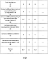
- FIG. 5 is a data structure illustrating costs calculated using different cost functions for a set of speed control rate candidates 501
- costs 502 are then calculated for the speed control rate candidates 501.
- the difference between the current speed control position and the target speed control position in a current command cycle is 50.
- the cost for speed control rate candidate of 30 is greater than the potential target speed control rate of 30, therefore the cost will be 20 (i.e., the difference of 50 subtracts the target speed control rate of 30).
- the cost for speed control rate candidates of 60 and 80 will be 0, since the speed control rate candidates are greater than or equal to the difference of 50.
- past speed-based cost function 412 is used by past speed-based cost module 402 to calculate a cost based on a difference between the previous target speed and the previous actual speed ended up in a previous command cycle, i.e., the difference between the "current" speed and the target speed of the previous command cycle.
- a previous command cycle refers to the last command cycle immediately before the current command cycle.
- Difference herein refers to the difference between a target vehicle speed and the actual vehicle speed ended up in a previous command cycle.
- the difference between the past target speed and the past actual speed is 5.
- the cost for the remaining speed control rate candidates of 60 and 80 can also be calculated using the above algorithm as of 8.3 and 6.25.
- the current speed-based cost 504 may be calculated by current speed-based cost module 403 (e.g., current speed-based cost function 413) based on the current vehicle speed in view of the current speed control rate candidate.
- cost 504 may be determined based on a difference between the current vehicle speed and the speed control rate candidate in question. In a particular embodiment, if the speed control rate candidate is larger than or equal to the current speed, cost 504 will be assigned with the difference; otherwise, the cost will be assigned with a predetermined value, in this example as shown in Figure 5 , zero. Therefore, cost 504 for speed control rate candidate of 30 will be zero since the vehicle speed is larger than the speed control rate candidate. Cost 504 for speed control rate candidates of 60 and 80 will be their respective differences, i.e., 10 and 30.
- the target rate-based cost 505 can be calculated by target rate-based cost module 404 using target rate-based cost function 414, such as a linear cost function.
- target rate-based cost function 414 such as a linear cost function.
- the cost is proportional to the target speed control rate: as higher speed control rate costs more.
- the cost for a given speed control rate candidate, the target rate-based cost 505 equals to the speed control rate candidate itself as 30, 60, and 80 as shown in Figure 5 .
- steering position-based cost 506 can be calculated by steering position-based cost module 405 using steering position-based cost function 415 based on a current steering position (in degrees) and the target speed control rate candidate.
- cost 506 may be determined based on a difference between the current steering position and the speed control rate candidate in question. The rationale behind it is that if the steering position is high, the cost to accelerate or decelerate will be higher since the vehicle is turning. It will be more dangerous or uncomfortable for higher acceleration or deceleration if the vehicle is turning sharper.
- cost 506 will be assigned with the difference; otherwise, the cost will be assigned with a predetermined value, in this example as shown in Figure 5 , zero. Therefore, assuming the current steering position is 40, cost 506 for speed control rate candidate of 30 will be zero since the steering position is larger than the speed control rate candidate. Cost 506 for speed control rate candidates of 60 and 80 will be their respective differences, i.e., 20 and 40.
- total cost 506 for each of the speed control rate candidates 501 is calculated, for example, by summing individual costs 502-506.
- One of the speed control rate candidates 501 having the lowest total cost 507(in this example, candidate of 100) is then selected as the target speed control rate for a subsequent command cycle for speed control.
- speed control rate determination model 600 may be created and trained by a machine learning engine such as machine learning engine 122 of data analytics system 103. Model 600 may be trained based on a large amount of driving statistics 123 offline.
- a set of driving statistics 601 is captured and fed into model 600 in view of a set of speed control rate candidates 602, which can be throttle or braking rate candidates.
- Model 600 may perform at least some of the above operations to determine and select one of the speed control rate candidates 602 as a target speed control rate 603 for generating a speed control command of a next command cycle.
- a command cycle refers to a period of time or frequency during which a control command will be generated and issue to the vehicle hardware. For example, if a control command will be issued for every 0.1 second, the time period of 0.1 second is referred to as a command cycle.
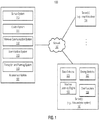
- FIG. 7 is a flow diagram illustrating a process of a determining speed control rate for operating an autonomous vehicle according to one embodiment of the invention.
- Process 700 may be performed by processing logic which may include software, hardware, or a combination thereof.
- processing logic may be performed by control module 305.
- processing logic determines a number of speed control rate candidates for speed control of an ADV (e.g., acceleration, deceleration, or maintaining a constant speed).
- the speed control rate candidates e.g., throttle rate or brake rate
- processing logic applies one or more cost functions to calculate one or more individual costs representing an impact of the speed control rate candidate to operate the ADV.
- Each cost functions corresponds to one of the cost categories (e.g., current position-based, past speed-based, current speed-based, target rate-based, and steering position-based categories).
- a total cost is determined based on the individual costs for each of the speed control rate candidates.
- one of the speed control rate candidates having the lowest total cost is selected as a target speed control rate for a subsequent command cycle for speed control of the ADV.
- a speed control command is generated based on the target speed control rate to control a speed of the ADV.
- FIG. 8 is a flow diagram illustrating a process of a determining speed control rate for operating an autonomous vehicle according to another embodiment of the invention.
- Process 800 may be performed by processing logic which may include software, hardware, or a combination thereof.
- process 800 may be performed by control module 305 as part of operations 702-703 of Figure 7 .
- processing logic calculates a first cost based on a target speed control position and a current speed control position (of the current command cycle) using a first cost function (e.g., current position-based cost function 411). If the difference between the target and current speed control positions is less than the target speed control rate (e.g., current speed control rate candidate in question), the first cost is zero; otherwise, the first cost equals to the difference between the target and current speed control positions.
- a first cost function e.g., current position-based cost function 411
- processing logic calculates a second cost based on a past target speed and a past actual speed ended up of a previous command cycle using a second cost function (e.g., past speed-based cost function 412).
- processing logic calculates a third cost based on a current vehicle speed of the ADV using a third cost function (e.g., current speed-based cost function 413).
- processing logic calculates a fourth cost based on the target speed control rate (e.g., speed control rate candidate in question) using a fourth cost function (e.g., target rate-based cost function 414).
- processing logic calculates a fifth cost based on a current steering position of the ADV using a fifth cost function (e.g., steering position-based cost function 415).
- a total cost is calculated based on the first cost, the second cost, the third cost, the fourth cost, and the fifth cost.
- components as shown and described above may be implemented in software, hardware, or a combination thereof.
- such components can be implemented as software installed and stored in a persistent storage device, which can be loaded and executed in a memory by a processor (not shown) to carry out the processes or operations described throughout this application.
- such components can be implemented as executable code programmed or embedded into dedicated hardware such as an integrated circuit (e.g., an application specific IC or ASIC), a digital signal processor (DSP), or a field programmable gate array (FPGA), which can be accessed via a corresponding driver and/or operating system from an application.
- an integrated circuit e.g., an application specific IC or ASIC
- DSP digital signal processor
- FPGA field programmable gate array
- such components can be implemented as specific hardware logic in a processor or processor core as part of an instruction set accessible by a software component via one or more specific instructions.
- FIG 9 is a block diagram illustrating an example of a data processing system which may be used with one embodiment of the invention.
- system 1500 may represent any of data processing systems described above performing any of the processes or methods described above, such as, for example, perception and planning system 110 or any of servers 103-104 of Figure 1 .
- System 1500 can include many different components. These components can be implemented as integrated circuits (ICs), portions thereof, discrete electronic devices, or other modules adapted to a circuit board such as a motherboard or add-in card of the computer system, or as components otherwise incorporated within a chassis of the computer system.
- ICs integrated circuits
- System 1500 is intended to show a high level view of many components of the computer system. However, it is to be understood that additional components may be present in certain implementations and furthermore, different arrangement of the components shown may occur in other implementations.
- System 1500 may represent a desktop, a laptop, a tablet, a server, a mobile phone, a media player, a personal digital assistant (PDA), a Smartwatch, a personal communicator, a gaming device, a network router or hub, a wireless access point (AP) or repeater, a set-top box, or a combination thereof.
- PDA personal digital assistant
- AP wireless access point
- system 1500 is intended to show a high level view of many components of the computer system. However, it is to be understood that additional components may be present in certain implementations and furthermore, different arrangement of the components shown may occur in other implementations.
- System 1500 may represent a desktop, a laptop, a tablet, a server, a mobile phone, a media player, a personal digital assistant (PDA),
- system 1500 includes processor 1501, memory 1503, and devices 1505-1508 via a bus or an interconnect 1510.
- Processor 1501 may represent a single processor or multiple processors with a single processor core or multiple processor cores included therein.
- Processor 1501 may represent one or more general-purpose processors such as a microprocessor, a central processing unit (CPU), or the like. More particularly, processor 1501 may be a complex instruction set computing (CISC) microprocessor, reduced instruction set computing (RISC) microprocessor, very long instruction word (VLIW) microprocessor, or processor implementing other instruction sets, or processors implementing a combination of instruction sets.
- CISC complex instruction set computing
- RISC reduced instruction set computing
- VLIW very long instruction word
- Processor 1501 may also be one or more special-purpose processors such as an application specific integrated circuit (ASIC), a cellular or baseband processor, a field programmable gate array (FPGA), a digital signal processor (DSP), a network processor, a graphics processor, a communications processor, a cryptographic processor, a co-processor, an embedded processor, or any other type of logic capable of processing instructions.
- ASIC application specific integrated circuit
- FPGA field programmable gate array
- DSP digital signal processor
- network processor a graphics processor
- communications processor a cryptographic processor
- co-processor a co-processor
- embedded processor or any other type of logic capable of processing instructions.
- Processor 1501 which may be a low power multi-core processor socket such as an ultra-low voltage processor, may act as a main processing unit and central hub for communication with the various components of the system. Such processor can be implemented as a system on chip (SoC). Processor 1501 is configured to execute instructions for performing the operations and steps discussed herein.
- System 1500 may further include a graphics interface that communicates with optional graphics subsystem 1504, which may include a display controller, a graphics processor, and/or a display device.
- Processor 1501 may communicate with memory 1503, which in one embodiment can be implemented via multiple memory devices to provide for a given amount of system memory.
- Memory 1503 may include one or more volatile storage (or memory) devices such as random access memory (RAM), dynamic RAM (DRAM), synchronous DRAM (SDRAM), static RAM (SRAM), or other types of storage devices.
- RAM random access memory
- DRAM dynamic RAM
- SDRAM synchronous DRAM
- SRAM static RAM
- Memory 1503 may store information including sequences of instructions that are executed by processor 1501, or any other device. For example, executable code and/or data of a variety of operating systems, device drivers, firmware (e.g., input output basic system or BIOS), and/or applications can be loaded in memory 1503 and executed by processor 1501.
- BIOS input output basic system
- An operating system can be any kind of operating systems, such as, for example, Robot Operating System (ROS), Windows® operating system from Microsoft®, Mac OS®/iOS® from Apple, Android® from Google®, LINUX, UNIX, or other real-time or embedded operating systems.
- ROS Robot Operating System
- Windows® operating system from Microsoft®
- Mac OS®/iOS® from Apple
- Android® from Google®
- LINUX LINUX
- UNIX or other real-time or embedded operating systems.
- System 1500 may further include IO devices such as devices 1505-1508, including network interface device(s) 1505, optional input device(s) 1506, and other optional IO device(s) 1507.
- Network interface device 1505 may include a wireless transceiver and/or a network interface card (NIC).
- the wireless transceiver may be a WiFi transceiver, an infrared transceiver, a Bluetooth transceiver, a WiMax transceiver, a wireless cellular telephony transceiver, a satellite transceiver (e.g., a global positioning system (GPS) transceiver), or other radio frequency (RF) transceivers, or a combination thereof.
- the NIC may be an Ethernet card.
- Input device(s) 1506 may include a mouse, a touch pad, a touch sensitive screen (which may be integrated with display device 1504), a pointer device such as a stylus, and/or a keyboard (e.g., physical keyboard or a virtual keyboard displayed as part of a touch sensitive screen).
- input device 1506 may include a touch screen controller coupled to a touch screen.
- the touch screen and touch screen controller can, for example, detect contact and movement or break thereof using any of a plurality of touch sensitivity technologies, including but not limited to capacitive, resistive, infrared, and surface acoustic wave technologies, as well as other proximity sensor arrays or other elements for determining one or more points of contact with the touch screen.
- IO devices 1507 may include an audio device.
- An audio device may include a speaker and/or a microphone to facilitate voice-enabled functions, such as voice recognition, voice replication, digital recording, and/or telephony functions.
- Other IO devices 1507 may further include universal serial bus (USB) port(s), parallel port(s), serial port(s), a printer, a network interface, a bus bridge (e.g., a PCI-PCI bridge), sensor(s) (e.g., a motion sensor such as an accelerometer, gyroscope, a magnetometer, a light sensor, compass, a proximity sensor, etc.), or a combination thereof.
- USB universal serial bus
- sensor(s) e.g., a motion sensor such as an accelerometer, gyroscope, a magnetometer, a light sensor, compass, a proximity sensor, etc.
- Devices 1507 may further include an imaging processing subsystem (e.g., a camera), which may include an optical sensor, such as a charged coupled device (CCD) or a complementary metal-oxide semiconductor (CMOS) optical sensor, utilized to facilitate camera functions, such as recording photographs and video clips.
- an imaging processing subsystem e.g., a camera
- an optical sensor such as a charged coupled device (CCD) or a complementary metal-oxide semiconductor (CMOS) optical sensor, utilized to facilitate camera functions, such as recording photographs and video clips.
- CCD charged coupled device
- CMOS complementary metal-oxide semiconductor
- Certain sensors may be coupled to interconnect 1510 via a sensor hub (not shown), while other devices such as a keyboard or thermal sensor may be controlled by an embedded controller (not shown), dependent upon the specific configuration or design of system 1500.
- a mass storage may also couple to processor 1501.
- this mass storage may be implemented via a solid state device (SSD).
- the mass storage may primarily be implemented using a hard disk drive (HDD) with a smaller amount of SSD storage to act as a SSD cache to enable non-volatile storage of context state and other such information during power down events so that a fast power up can occur on re-initiation of system activities.
- a flash device may be coupled to processor 1501, e.g., via a serial peripheral interface (SPI). This flash device may provide for non-volatile storage of system software, including BIOS as well as other firmware of the system.
- Storage device 1508 may include computer-accessible storage medium 1509 (also known as a machine-readable storage medium or a computer-readable medium) on which is stored one or more sets of instructions or software (e.g., module, unit, and/or logic 1528) embodying any one or more of the methodologies or functions described herein.
- Processing module/unit/logic 1528 may represent any of the components described above, such as, for example, control module 305.
- Processing module/unit/logic 1528 may also reside, completely or at least partially, within memory 1503 and/or within processor 1501 during execution thereof by data processing system 1500, memory 1503 and processor 1501 also constituting machine-accessible storage media.
- Processing module/unit/logic 1528 may further be transmitted or received over a network via network interface device 1505.
- Computer-readable storage medium 1509 may also be used to store the some software functionalities described above persistently. While computer-readable storage medium 1509 is shown in an exemplary embodiment to be a single medium, the term "computer-readable storage medium” should be taken to include a single medium or multiple media (e.g., a centralized or distributed database, and/or associated caches and servers) that store the one or more sets of instructions. The terms “computer-readable storage medium” shall also be taken to include any medium that is capable of storing or encoding a set of instructions for execution by the machine and that cause the machine to perform any one or more of the methodologies of the present invention. The term “computer-readable storage medium” shall accordingly be taken to include, but not be limited to, solid-state memories, and optical and magnetic media, or any other non-transitory machine-readable medium.
- Processing module/unit/logic 1528, components and other features described herein can be implemented as discrete hardware components or integrated in the functionality of hardware components such as ASICS, FPGAs, DSPs or similar devices.
- processing module/unit/logic 1528 can be implemented as firmware or functional circuitry within hardware devices.
- processing module/unit/logic 1528 can be implemented in any combination hardware devices and software components.
- system 1500 is illustrated with various components of a data processing system, it is not intended to represent any particular architecture or manner of interconnecting the components; as such details are not germane to embodiments of the present invention. It will also be appreciated that network computers, handheld computers, mobile phones, servers, and/or other data processing systems which have fewer components or perhaps more components may also be used with embodiments of the invention.
- Embodiments of the invention also relate to an apparatus for performing the operations herein.
- a computer program is stored in a non-transitory computer readable medium.
- a machine-readable medium includes any mechanism for storing information in a form readable by a machine (e.g., a computer).
- a machine-readable (e.g., computer-readable) medium includes a machine (e.g., a computer) readable storage medium (e.g., read only memory (“ROM”), random access memory (“RAM”), magnetic disk storage media, optical storage media, flash memory devices).
- processing logic that comprises hardware (e.g. circuitry, dedicated logic, etc.), software (e.g., embodied on a non-transitory computer readable medium), or a combination of both.
- processing logic comprises hardware (e.g. circuitry, dedicated logic, etc.), software (e.g., embodied on a non-transitory computer readable medium), or a combination of both.
- Embodiments of the present invention are not described with reference to any particular programming language. It will be appreciated that a variety of programming languages may be used to implement the teachings of embodiments of the invention as described herein.
Claims (13)
- Procédé implémenté par ordinateur pour la détermination d'un taux de contrôle de vitesse pour le fonctionnement d'un véhicule autonome, ce procédé comprenant :la détermination (701) d'une pluralité de candidats de taux de contrôle de vitesse (501) pour une commande de contrôle de vitesse de fonctionnement d'un véhicule autonome ;pour chacun des candidats de taux de contrôle de vitesse,le calcul (702) d'une pluralité de coûts individuels (502, 503, 504, 505, 506) pour le candidat de taux de contrôle de vitesse en appliquant une pluralité de fonctions de coûts, chaque fonction de coût correspondant à une parmi une pluralité de catégories de coûts etle calcul (703) d'un coût total (507) pour le candidat de taux de contrôle de vitesse sur la base des coûts individuels (502, 503, 504, 505, 506) produits par les fonctions de coûts ;la sélection (704) d'un des candidats de taux de contrôle de vitesse (501) ayant le coût total le plus bas en tant que taux de contrôle de vitesse cible ; etla génération (705) d'une commande de contrôle de vitesse sur la base du candidat de taux de contrôle de vitesse sélectionné pour contrôler une vitesse du véhicule autonome,ce procédé étant caractérisé en ce queun taux de contrôle de vitesse se réfère à une quantité de changement d'une position de contrôle de vitesse etla position de contrôle de vitesse se réfère à une position d'accélération ou de freinage en pourcentage d'une valeur maximale d'accélération ou de freinage ; eten ce que le calcul d'un coût individuel pour le candidat de taux de contrôle de vitesse comprend
le calcul (802) d'un coût individuel basé sur une vitesse passée (503) sur la base d'une différence entre une vitesse de véhicule cible précédente et une vitesse de véhicule réelle précédente du véhicule autonome dans le cycle de commande précédent à l'aide d'une fonction de coût basée sur une vitesse passée (412). - Procédé selon la revendication 1, dans lequel le calcul d'un coût individuel pour le candidat de taux de contrôle de vitesse comprend le calcul (801) d'un premier coût individuel (502) sur la base d'une différence entre une position de contrôle de vitesse cible et une position de contrôle de vitesse actuelle du véhicule autonome à l'aide d'une première fonction de coût ;
de préférence ce procédé comprend :l'assignation du premier coût individuel en tant que différence entre la position de contrôle de vitesse cible et la position de contrôle de vitesse actuelle si le candidat de taux de contrôle de vitesse est supérieur à la différence ; etl'assignation du premier coût individuel en tant que valeur prédéterminée si la différence est supérieure ou égale au candidat de taux de contrôle de vitesse. - Procédé selon la revendication 1, dans lequel le calcul d'un coût individuel pour le candidat de taux de contrôle de vitesse comprend le calcul (803) d'un troisième coût individuel (504) sur la base d'une vitesse de véhicule actuelle du véhicule autonome et le candidat de taux de contrôle de vitesse à l'aide d'une troisième fonction de coût.
- Procédé selon la revendication 1, dans lequel le calcul d'un coût individuel pour le candidat de taux de contrôle de vitesse comprend le calcul (804) d'un quatrième coût individuel (505) sur la base du candidat de taux de contrôle de vitesse en tant que taux de contrôle de vitesse cible à l'aide d'une quatrième fonction de coût.
- Procédé selon la revendication 1, dans lequel le calcul d'un coût individuel pour le candidat de taux de contrôle de vitesse comprend le calcul (805) d'un cinquième coût individuel (506) sur la base d'une position de direction actuelle du véhicule autonome et du candidat de taux de contrôle de vitesse.
- Support non transitoire lisible par une machine comprenant des instructions stockées à l'intérieur, qui, lorsqu'elles sont exécutées par un processeur, font en sorte que le processeur effectue des opérations, ces opérations comprenant :la détermination (701) d'une pluralité de candidats de taux de contrôle de vitesse (501) pour une commande de contrôle de vitesse de fonctionnement d'un véhicule autonome, pour chacun des candidats de taux de contrôle de vitesse,le calcul (702) d'une pluralité de coûts individuels (502, 503, 504, 505, 506) pour le candidat de taux de contrôle de vitesse en appliquant une pluralité de fonctions de coûts, chaque fonction de coût correspondant à une parmi une pluralité de catégories de coûts etle calcul (703) d'un coût total (507) pour le candidat de taux de contrôle de vitesse sur la base des coûts individuels (502, 503, 504, 505, 506) produits par les fonctions de coûts ;la sélection (704) d'un des candidats de taux de contrôle de vitesse (501) ayant le coût total le plus bas en tant que taux de contrôle de vitesse cible ; etla génération (705) d'une commande de contrôle de vitesse sur la base du candidat de taux de contrôle de vitesse sélectionné pour contrôler une vitesse du véhicule autonome,caractérisé en ce queun taux de contrôle de vitesse se réfère à une quantité de changement d'une position de contrôle de vitesse, etla position de contrôle de vitesse se réfère à une position d'accélération ou de freinage en pourcentage d'une valeur maximale d'accélération ou de freinage ; eten ce que le calcul d'un coût individuel pour le candidat de taux de contrôle de vitesse comprend le calcul d'un coût individuel basé sur une vitesse passée sur la base d'une différence entre une vitesse de véhicule cible précédente et une vitesse de véhicule réelle précédente du véhicule autonome dans le cycle de commande précédent à l'aide d'une fonction de coût basée sur une vitesse passée.
- Support lisible par une machine selon la revendication 6, dans lequel le calcul d'un coût individuel pour le candidat de taux de contrôle de vitesse comprend le calcul (801) d'un premier coût individuel (502) sur la base d'une différence entre une position de contrôle de vitesse cible et une position de contrôle de vitesse actuelle du véhicule autonome à l'aide d'une première fonction de coût ;
de préférence, les opérations comprennent en outre :l'assignation du premier coût individuel en tant que différence entre la position de contrôle de vitesse cible et la position de contrôle de vitesse actuelle si le candidat de taux de contrôle de vitesse est supérieur à la différence ; etl'assignation du premier coût individuel en tant que valeur prédéterminée si la différence est supérieure ou égale au candidat de taux de contrôle de vitesse. - Support lisible par une machine selon la revendication 6, dans lequel le calcul d'un coût individuel pour le candidat de taux de contrôle de vitesse comprend le calcul (803) d'un troisième coût individuel (504) sur la base d'une vitesse de véhicule actuelle du véhicule autonome et le candidat de taux de contrôle de vitesse à l'aide d'une troisième fonction de coût.
- Support lisible par une machine selon la revendication 6, dans lequel le calcul d'un coût individuel pour le candidat de taux de contrôle de vitesse comprend le calcul (804) d'un quatrième coût individuel (505) sur la base du candidat de taux de contrôle de vitesse en tant que taux de contrôle de vitesse cible à l'aide d'une quatrième fonction de coût.
- Support lisible par une machine selon la revendication 6, dans lequel le calcul d'un coût individuel pour le candidat de taux de contrôle de vitesse comprend le calcul (805) d'un cinquième coût individuel (506) sur la base d'une position de direction actuelle du véhicule autonome et du candidat de taux de contrôle de vitesse.
- Système de traitement de commande comprenant :un processeur ; etune mémoire couplée au processeur pour stocker des instructions qui, lorsqu'elles sont exécutées par un processeur, font en sorte que le processeur effectue des opérations, ces opérations comprenant :la détermination (701) d'une pluralité de candidats de taux de contrôle de vitesse (501) pour une commande de contrôle de vitesse de fonctionnement d'un véhicule autonome, pour chacun des candidats de taux de contrôle de vitesse,le calcul (702) d'une pluralité de coûts individuels (502, 503, 504, 505, 506) pour le candidat de taux de contrôle de vitesse en appliquant une pluralité de fonctions de coûts, chaque fonction de coût correspondant à une parmi une pluralité de catégories de coûts etle calcul (703) d'un coût total (507) pour le candidat de taux de contrôle de vitesse sur la base des coûts individuels (502, 503, 504, 505, 506) produits par les fonctions de coûts ;la sélection (704) d'un des candidats de taux de contrôle de vitesse (501) ayant le coût total le plus bas en tant que taux de contrôle de vitesse cible ; etla génération (705) d'une commande de contrôle de vitesse sur la base du candidat de taux de contrôle de vitesse sélectionné pour contrôler une vitesse du véhicule autonome,caractérisé en ce queun taux de contrôle de vitesse se réfère à une quantité de changement d'une position de contrôle de vitesse etla position de contrôle de vitesse se réfère à une position d'accélération ou de freinage en pourcentage d'une valeur maximale d'accélération ou de freinage ; eten ce que le calcul d'un coût individuel pour le candidat de taux de contrôle de vitesse comprend le calcul d'un coût individuel basé sur une vitesse passée sur la base d'une différence entre une vitesse de véhicule cible précédente et une vitesse de véhicule réelle précédente du véhicule autonome dans le cycle de commande précédent à l'aide d'une fonction de coût basée sur une vitesse passée.
- Système selon la revendication 11, dans lequel le calcul d'un coût individuel pour le candidat de taux de contrôle de vitesse comprend le calcul (801) d'un premier coût individuel (502) sur la base d'une différence entre une position de contrôle de vitesse cible et une position de contrôle de vitesse actuelle du véhicule autonome à l'aide d'une première fonction de coût.
- Système selon la revendication 12, dans lequel les opérations comprennent :l'assignation du premier coût individuel (502) en tant que différence entre la position de contrôle de vitesse cible et la position de contrôle de vitesse actuelle si le candidat de taux de contrôle de vitesse est supérieur à la différence ; etl'assignation du premier coût individuel (502) en tant que valeur prédéterminée si la différence est supérieure ou égale au candidat de taux de contrôle de vitesse.
Applications Claiming Priority (1)
| Application Number | Priority Date | Filing Date | Title |
|---|---|---|---|
| US15/393,158 US11584372B2 (en) | 2016-12-28 | 2016-12-28 | Method to dynamically adjusting speed control rates of autonomous vehicles |
Publications (2)
| Publication Number | Publication Date |
|---|---|
| EP3342670A1 EP3342670A1 (fr) | 2018-07-04 |
| EP3342670B1 true EP3342670B1 (fr) | 2020-12-09 |
Family
ID=59901391
Family Applications (1)
| Application Number | Title | Priority Date | Filing Date |
|---|---|---|---|
| EP17191258.7A Active EP3342670B1 (fr) | 2016-12-28 | 2017-09-15 | Procédé d'ajustement dynamique de la variation de commande de vitesse de véhicules autonomes |
Country Status (4)
| Country | Link |
|---|---|
| US (1) | US11584372B2 (fr) |
| EP (1) | EP3342670B1 (fr) |
| JP (1) | JP6494715B2 (fr) |
| CN (1) | CN108255170B (fr) |
Families Citing this family (15)
| Publication number | Priority date | Publication date | Assignee | Title |
|---|---|---|---|---|
| US10438074B2 (en) * | 2017-06-14 | 2019-10-08 | Baidu Usa Llc | Method and system for controlling door locks of autonomous driving vehicles based on lane information |
| US11214251B2 (en) * | 2018-07-09 | 2022-01-04 | Baidu Usa Llc | Speed control command auto-calibration system for autonomous vehicles |
| KR102211298B1 (ko) * | 2018-08-24 | 2021-02-04 | 바이두닷컴 타임즈 테크놀로지(베이징) 컴퍼니 리미티드 | 센서 간의 데이터 전송을 위한 데이터 전송 로직과 자율 주행 차량의 계획 및 제어 |
| EP3652601B1 (fr) * | 2018-09-28 | 2021-05-19 | Baidu.com Times Technology (Beijing) Co., Ltd. | Planification de demi-tour en trois temps pour véhicules à conduite autonome |
| US10908613B2 (en) * | 2018-10-15 | 2021-02-02 | Baidu Usa Llc | Optimal longitudinal trajectory generation under varied lateral acceleration constraints |
| US11086327B2 (en) * | 2018-11-05 | 2021-08-10 | Wipro Limited | Method and system for determining safe navigation of autonomous vehicle |
| EP3870491A4 (fr) * | 2018-12-10 | 2022-03-23 | Huawei Technologies Co., Ltd. | Apprentissage de style de conduite personnel pour une conduite autonome |
| CN109782758B (zh) * | 2018-12-29 | 2022-03-22 | 百度在线网络技术(北京)有限公司 | 用于自动驾驶车辆的弯道速度计算方法、控制方法及装置 |
| US11126179B2 (en) * | 2019-02-21 | 2021-09-21 | Zoox, Inc. | Motion prediction based on appearance |
| CN109814576B (zh) * | 2019-02-22 | 2022-01-28 | 百度在线网络技术(北京)有限公司 | 自动驾驶车辆的速度规划方法、装置和存储介质 |
| CN109655076B (zh) * | 2019-02-22 | 2021-03-09 | 百度在线网络技术(北京)有限公司 | 车辆转弯的速度规划方法、装置和存储介质 |
| US11561543B2 (en) * | 2019-12-11 | 2023-01-24 | Baidu Usa Llc | Speed planning using a speed planning guideline for idle speed of autonomous driving vehicles |
| US11604468B2 (en) | 2019-12-24 | 2023-03-14 | Valeo Schalter Und Sensoren Gmbh | Techniques for blended control for remote operations |
| US11087623B1 (en) * | 2020-01-29 | 2021-08-10 | Toyota Motor Engineering & Manufacturing North America, Inc. | Systems and methods for compensating for driver speed-tracking error |
| CN112527002B (zh) * | 2021-02-18 | 2021-06-18 | 北京图森智途科技有限公司 | 监控装置和监控方法 |
Family Cites Families (32)
| Publication number | Priority date | Publication date | Assignee | Title |
|---|---|---|---|---|
| US2447730A (en) * | 1943-10-18 | 1948-08-24 | Karl B Britton | Gear shifting mechanism |
| US4924397A (en) * | 1986-12-08 | 1990-05-08 | Honda Giken Kogyo K.K. | Vehicle cruise control system |
| JP3197307B2 (ja) | 1991-10-14 | 2001-08-13 | マツダ株式会社 | 移動車の走行制御装置 |
| GB2372020A (en) * | 2001-02-07 | 2002-08-14 | Lucas Industries Ltd | Haptic controller for electrically-assisted power steering in road vehicles |
| DE10307169A1 (de) | 2003-02-20 | 2004-09-02 | Daimlerchrysler Ag | Verfahren zur Regelung der Fahrgeschwindigkeit eines Fahrzeugs |
| JP4655723B2 (ja) * | 2005-03-31 | 2011-03-23 | トヨタ自動車株式会社 | 車両およびその制御方法 |
| US20070055431A1 (en) | 2005-09-07 | 2007-03-08 | Weiwen Deng | Method and apparatus for preview-based vehicle lateral control |
| US8396634B2 (en) * | 2007-11-04 | 2013-03-12 | GM Global Technology Operations LLC | Method and apparatus for maximum and minimum output torque performance by selection of hybrid range state and input speed for a hybrid powertrain system |
| JP5218182B2 (ja) * | 2008-08-28 | 2013-06-26 | 日産自動車株式会社 | 車速制限制御装置 |
| JP2010084867A (ja) * | 2008-09-30 | 2010-04-15 | Aisin Aw Co Ltd | 自動変速機の制御装置 |
| US8126642B2 (en) * | 2008-10-24 | 2012-02-28 | Gray & Company, Inc. | Control and systems for autonomously driven vehicles |
| FR2939917B1 (fr) * | 2008-12-12 | 2012-09-21 | Thales Sa | Procede et dispositif pour l'optimisation du vol d'un aeronef |
| JP5142047B2 (ja) * | 2009-02-26 | 2013-02-13 | アイシン・エィ・ダブリュ株式会社 | ナビゲーション装置及びナビゲーション用プログラム |
| DE102009030784A1 (de) | 2009-06-27 | 2010-02-04 | Daimler Ag | Verfahren zum Steuern des Betriebs eines Fahrzeugs |
| US9098084B2 (en) * | 2011-02-14 | 2015-08-04 | Murata Machinery, Ltd. | Transport carriage system and method for controlling running of transport carriage |
| US8775006B2 (en) | 2011-07-14 | 2014-07-08 | GM Global Technology Operations LLC | System and method for enhanced vehicle control |
| US8965633B2 (en) * | 2011-09-02 | 2015-02-24 | GM Global Technology Operations LLC | System and method for speed adaptive steering override detection during automated lane centering |
| KR102070470B1 (ko) * | 2012-03-16 | 2020-01-29 | 알리손 트랜스미션, 인크. | 언덕을 상승 및/또는 하강하기 위한 보조기능을 제공하기 위해 변속기 토크를 제어하기 위한 장치 및 방법 |
| WO2014011992A2 (fr) * | 2012-07-13 | 2014-01-16 | Love Park Robotics, Llc | Systèmes de commande de conduite pour véhicules tels que des véhicules de transport personnel |
| US8712663B1 (en) | 2012-10-31 | 2014-04-29 | GM Global Technology Operations LLC | Systems and methods for vehicle cruise control |
| CN103057436B (zh) * | 2012-12-27 | 2015-07-01 | 西安交通大学 | 一种基于多智能体的独立驱动电动汽车横摆力矩控制方法 |
| WO2014149043A1 (fr) * | 2013-03-20 | 2014-09-25 | International Truck Intellectual Property Company, Llc | Système de commande de vitesse de croisière intelligent |
| US20150025917A1 (en) * | 2013-07-15 | 2015-01-22 | Advanced Insurance Products & Services, Inc. | System and method for determining an underwriting risk, risk score, or price of insurance using cognitive information |
| JP5839010B2 (ja) * | 2013-09-11 | 2016-01-06 | トヨタ自動車株式会社 | 運転支援装置 |
| JP6308032B2 (ja) | 2014-06-04 | 2018-04-11 | 株式会社デンソー | 運転操作を生成するシステムおよび方法 |
| US9707960B2 (en) * | 2014-07-31 | 2017-07-18 | Waymo Llc | Traffic signal response for autonomous vehicles |
| WO2016095825A1 (fr) * | 2014-12-16 | 2016-06-23 | 比亚迪股份有限公司 | Véhicule électrique, système de commande de sécurité actif pour véhicule électrique et son procédé de commande |
| US20160288788A1 (en) | 2015-03-31 | 2016-10-06 | Toyota Motor Engineering & Manufacturing North America, Inc. | Gap-based speed control for automated driving system |
| DE102015211134A1 (de) | 2015-06-17 | 2016-12-22 | Bayerische Motoren Werke Aktiengesellschaft | Verfahren und Steuereinheit zur Steuerung eines Fahrzeugs bei Übernahme aus einem autonomen Fahrmodus |
| US10239529B2 (en) * | 2016-03-01 | 2019-03-26 | Ford Global Technologies, Llc | Autonomous vehicle operation based on interactive model predictive control |
| CN105987696A (zh) * | 2016-04-20 | 2016-10-05 | 上海雷易工业自动化有限公司 | 一种低成本车辆自动驾驶设计实现方法 |
| CN106002991A (zh) * | 2016-05-25 | 2016-10-12 | 北京百度网讯科技有限公司 | 基于人工智能的智能机器人 |
-
2016
- 2016-12-28 US US15/393,158 patent/US11584372B2/en active Active
-
2017
- 2017-09-12 CN CN201710816194.6A patent/CN108255170B/zh active Active
- 2017-09-13 JP JP2017175379A patent/JP6494715B2/ja active Active
- 2017-09-15 EP EP17191258.7A patent/EP3342670B1/fr active Active
Non-Patent Citations (1)
| Title |
|---|
| None * |
Also Published As
| Publication number | Publication date |
|---|---|
| US20180178791A1 (en) | 2018-06-28 |
| EP3342670A1 (fr) | 2018-07-04 |
| CN108255170A (zh) | 2018-07-06 |
| CN108255170B (zh) | 2021-10-26 |
| JP2018108800A (ja) | 2018-07-12 |
| US11584372B2 (en) | 2023-02-21 |
| JP6494715B2 (ja) | 2019-04-03 |
Similar Documents
| Publication | Publication Date | Title |
|---|---|---|
| EP3347785B1 (fr) | Réglage dynamique des vitesses de direction de véhicules autonomes | |
| EP3342670B1 (fr) | Procédé d'ajustement dynamique de la variation de commande de vitesse de véhicules autonomes | |
| EP3353494B1 (fr) | Procédé d'estimation de paramètres de régulation de vitesse de véhicules à conduite autonome | |
| EP3500965B1 (fr) | Commande de vitesse destinée à un arrêt complet d'un véhicule de conduite autonome | |
| EP3580625B1 (fr) | Lignes directrices de voie fondées sur des scénarios de conduite pour planifier des trajets de véhicules à conduite autonome | |
| EP3309640B1 (fr) | Cadre d'apprentissage de style de conduite de groupe pour véhicules autonomes | |
| EP3315388B1 (fr) | Approche de changement de voie basée sur un système de ressort pour des véhicules autonomes | |
| EP3327530B1 (fr) | Procédé permettant de déterminer des retards de commande de véhicules autonomes | |
| EP3562725B1 (fr) | Procédé et système pour déterminer les frottements de route de véhicules à conduite autonome à l'aide d'une commande prédictive de modèle basée sur l'apprentissage | |
| US10606273B2 (en) | System and method for trajectory re-planning of autonomous driving vehicles | |
| US10908608B2 (en) | Method and system for stitching planning trajectories from consecutive planning cycles for smooth control execution of autonomous driving vehicles | |
| US10569651B2 (en) | Speed control and steering control assistant based on pitch status and roll status of autonomous driving vehicle | |
| US10272778B2 (en) | Method and system for determining unit gain of speed control for autonomous driving vehicles | |
| EP3379364B1 (fr) | Système de commande et de planification à dominante de commande pour véhicules autonomes | |
| WO2018090289A1 (fr) | Procédé et système de suivi de vitesse de véhicule autonome | |
| EP3694756B1 (fr) | Système de planification de stationnement vertical fondé sur une courbe en spirale pour véhicules à conduite autonome | |
| EP3625635B1 (fr) | Système d'auto-étalonnage d'instruction de commande de vitesse pour véhicules autonomes |
Legal Events
| Date | Code | Title | Description |
|---|---|---|---|
| PUAI | Public reference made under article 153(3) epc to a published international application that has entered the european phase |
Free format text: ORIGINAL CODE: 0009012 |
|
| STAA | Information on the status of an ep patent application or granted ep patent |
Free format text: STATUS: THE APPLICATION HAS BEEN PUBLISHED |
|
| AK | Designated contracting states |
Kind code of ref document: A1 Designated state(s): AL AT BE BG CH CY CZ DE DK EE ES FI FR GB GR HR HU IE IS IT LI LT LU LV MC MK MT NL NO PL PT RO RS SE SI SK SM TR |
|
| AX | Request for extension of the european patent |
Extension state: BA ME |
|
| STAA | Information on the status of an ep patent application or granted ep patent |
Free format text: STATUS: REQUEST FOR EXAMINATION WAS MADE |
|
| 17P | Request for examination filed |
Effective date: 20190104 |
|
| RBV | Designated contracting states (corrected) |
Designated state(s): AL AT BE BG CH CY CZ DE DK EE ES FI FR GB GR HR HU IE IS IT LI LT LU LV MC MK MT NL NO PL PT RO RS SE SI SK SM TR |
|
| STAA | Information on the status of an ep patent application or granted ep patent |
Free format text: STATUS: EXAMINATION IS IN PROGRESS |
|
| 17Q | First examination report despatched |
Effective date: 20191111 |
|
| GRAP | Despatch of communication of intention to grant a patent |
Free format text: ORIGINAL CODE: EPIDOSNIGR1 |
|
| STAA | Information on the status of an ep patent application or granted ep patent |
Free format text: STATUS: GRANT OF PATENT IS INTENDED |
|
| INTG | Intention to grant announced |
Effective date: 20200715 |
|
| GRAS | Grant fee paid |
Free format text: ORIGINAL CODE: EPIDOSNIGR3 |
|
| GRAA | (expected) grant |
Free format text: ORIGINAL CODE: 0009210 |
|
| STAA | Information on the status of an ep patent application or granted ep patent |
Free format text: STATUS: THE PATENT HAS BEEN GRANTED |
|
| AK | Designated contracting states |
Kind code of ref document: B1 Designated state(s): AL AT BE BG CH CY CZ DE DK EE ES FI FR GB GR HR HU IE IS IT LI LT LU LV MC MK MT NL NO PL PT RO RS SE SI SK SM TR |
|
| REG | Reference to a national code |
Ref country code: GB Ref legal event code: FG4D |
|
| REG | Reference to a national code |
Ref country code: AT Ref legal event code: REF Ref document number: 1343133 Country of ref document: AT Kind code of ref document: T Effective date: 20201215 Ref country code: CH Ref legal event code: EP |
|
| REG | Reference to a national code |
Ref country code: DE Ref legal event code: R096 Ref document number: 602017029143 Country of ref document: DE |
|
| REG | Reference to a national code |
Ref country code: IE Ref legal event code: FG4D |
|
| PG25 | Lapsed in a contracting state [announced via postgrant information from national office to epo] |
Ref country code: GR Free format text: LAPSE BECAUSE OF FAILURE TO SUBMIT A TRANSLATION OF THE DESCRIPTION OR TO PAY THE FEE WITHIN THE PRESCRIBED TIME-LIMIT Effective date: 20210310 Ref country code: FI Free format text: LAPSE BECAUSE OF FAILURE TO SUBMIT A TRANSLATION OF THE DESCRIPTION OR TO PAY THE FEE WITHIN THE PRESCRIBED TIME-LIMIT Effective date: 20201209 Ref country code: NO Free format text: LAPSE BECAUSE OF FAILURE TO SUBMIT A TRANSLATION OF THE DESCRIPTION OR TO PAY THE FEE WITHIN THE PRESCRIBED TIME-LIMIT Effective date: 20210309 Ref country code: RS Free format text: LAPSE BECAUSE OF FAILURE TO SUBMIT A TRANSLATION OF THE DESCRIPTION OR TO PAY THE FEE WITHIN THE PRESCRIBED TIME-LIMIT Effective date: 20201209 |
|
| REG | Reference to a national code |
Ref country code: AT Ref legal event code: MK05 Ref document number: 1343133 Country of ref document: AT Kind code of ref document: T Effective date: 20201209 |
|
| PG25 | Lapsed in a contracting state [announced via postgrant information from national office to epo] |
Ref country code: SE Free format text: LAPSE BECAUSE OF FAILURE TO SUBMIT A TRANSLATION OF THE DESCRIPTION OR TO PAY THE FEE WITHIN THE PRESCRIBED TIME-LIMIT Effective date: 20201209 Ref country code: BG Free format text: LAPSE BECAUSE OF FAILURE TO SUBMIT A TRANSLATION OF THE DESCRIPTION OR TO PAY THE FEE WITHIN THE PRESCRIBED TIME-LIMIT Effective date: 20210309 Ref country code: LV Free format text: LAPSE BECAUSE OF FAILURE TO SUBMIT A TRANSLATION OF THE DESCRIPTION OR TO PAY THE FEE WITHIN THE PRESCRIBED TIME-LIMIT Effective date: 20201209 |
|
| REG | Reference to a national code |
Ref country code: NL Ref legal event code: MP Effective date: 20201209 |
|
| PG25 | Lapsed in a contracting state [announced via postgrant information from national office to epo] |
Ref country code: NL Free format text: LAPSE BECAUSE OF FAILURE TO SUBMIT A TRANSLATION OF THE DESCRIPTION OR TO PAY THE FEE WITHIN THE PRESCRIBED TIME-LIMIT Effective date: 20201209 Ref country code: HR Free format text: LAPSE BECAUSE OF FAILURE TO SUBMIT A TRANSLATION OF THE DESCRIPTION OR TO PAY THE FEE WITHIN THE PRESCRIBED TIME-LIMIT Effective date: 20201209 |
|
| REG | Reference to a national code |
Ref country code: LT Ref legal event code: MG9D |
|
| PG25 | Lapsed in a contracting state [announced via postgrant information from national office to epo] |
Ref country code: SK Free format text: LAPSE BECAUSE OF FAILURE TO SUBMIT A TRANSLATION OF THE DESCRIPTION OR TO PAY THE FEE WITHIN THE PRESCRIBED TIME-LIMIT Effective date: 20201209 Ref country code: PT Free format text: LAPSE BECAUSE OF FAILURE TO SUBMIT A TRANSLATION OF THE DESCRIPTION OR TO PAY THE FEE WITHIN THE PRESCRIBED TIME-LIMIT Effective date: 20210409 Ref country code: RO Free format text: LAPSE BECAUSE OF FAILURE TO SUBMIT A TRANSLATION OF THE DESCRIPTION OR TO PAY THE FEE WITHIN THE PRESCRIBED TIME-LIMIT Effective date: 20201209 Ref country code: SM Free format text: LAPSE BECAUSE OF FAILURE TO SUBMIT A TRANSLATION OF THE DESCRIPTION OR TO PAY THE FEE WITHIN THE PRESCRIBED TIME-LIMIT Effective date: 20201209 Ref country code: LT Free format text: LAPSE BECAUSE OF FAILURE TO SUBMIT A TRANSLATION OF THE DESCRIPTION OR TO PAY THE FEE WITHIN THE PRESCRIBED TIME-LIMIT Effective date: 20201209 Ref country code: EE Free format text: LAPSE BECAUSE OF FAILURE TO SUBMIT A TRANSLATION OF THE DESCRIPTION OR TO PAY THE FEE WITHIN THE PRESCRIBED TIME-LIMIT Effective date: 20201209 Ref country code: CZ Free format text: LAPSE BECAUSE OF FAILURE TO SUBMIT A TRANSLATION OF THE DESCRIPTION OR TO PAY THE FEE WITHIN THE PRESCRIBED TIME-LIMIT Effective date: 20201209 |
|
| PG25 | Lapsed in a contracting state [announced via postgrant information from national office to epo] |
Ref country code: PL Free format text: LAPSE BECAUSE OF FAILURE TO SUBMIT A TRANSLATION OF THE DESCRIPTION OR TO PAY THE FEE WITHIN THE PRESCRIBED TIME-LIMIT Effective date: 20201209 Ref country code: AT Free format text: LAPSE BECAUSE OF FAILURE TO SUBMIT A TRANSLATION OF THE DESCRIPTION OR TO PAY THE FEE WITHIN THE PRESCRIBED TIME-LIMIT Effective date: 20201209 |
|
| REG | Reference to a national code |
Ref country code: DE Ref legal event code: R097 Ref document number: 602017029143 Country of ref document: DE |
|
| PG25 | Lapsed in a contracting state [announced via postgrant information from national office to epo] |
Ref country code: IS Free format text: LAPSE BECAUSE OF FAILURE TO SUBMIT A TRANSLATION OF THE DESCRIPTION OR TO PAY THE FEE WITHIN THE PRESCRIBED TIME-LIMIT Effective date: 20210409 |
|
| PLBE | No opposition filed within time limit |
Free format text: ORIGINAL CODE: 0009261 |
|
| STAA | Information on the status of an ep patent application or granted ep patent |
Free format text: STATUS: NO OPPOSITION FILED WITHIN TIME LIMIT |
|
| PG25 | Lapsed in a contracting state [announced via postgrant information from national office to epo] |
Ref country code: IT Free format text: LAPSE BECAUSE OF FAILURE TO SUBMIT A TRANSLATION OF THE DESCRIPTION OR TO PAY THE FEE WITHIN THE PRESCRIBED TIME-LIMIT Effective date: 20201209 Ref country code: AL Free format text: LAPSE BECAUSE OF FAILURE TO SUBMIT A TRANSLATION OF THE DESCRIPTION OR TO PAY THE FEE WITHIN THE PRESCRIBED TIME-LIMIT Effective date: 20201209 |
|
| 26N | No opposition filed |
Effective date: 20210910 |
|
| PG25 | Lapsed in a contracting state [announced via postgrant information from national office to epo] |
Ref country code: DK Free format text: LAPSE BECAUSE OF FAILURE TO SUBMIT A TRANSLATION OF THE DESCRIPTION OR TO PAY THE FEE WITHIN THE PRESCRIBED TIME-LIMIT Effective date: 20201209 Ref country code: SI Free format text: LAPSE BECAUSE OF FAILURE TO SUBMIT A TRANSLATION OF THE DESCRIPTION OR TO PAY THE FEE WITHIN THE PRESCRIBED TIME-LIMIT Effective date: 20201209 |
|
| PG25 | Lapsed in a contracting state [announced via postgrant information from national office to epo] |
Ref country code: ES Free format text: LAPSE BECAUSE OF FAILURE TO SUBMIT A TRANSLATION OF THE DESCRIPTION OR TO PAY THE FEE WITHIN THE PRESCRIBED TIME-LIMIT Effective date: 20201209 |
|
| REG | Reference to a national code |
Ref country code: CH Ref legal event code: PL |
|
| REG | Reference to a national code |
Ref country code: BE Ref legal event code: MM Effective date: 20210930 |
|
| PG25 | Lapsed in a contracting state [announced via postgrant information from national office to epo] |
Ref country code: IS Free format text: LAPSE BECAUSE OF FAILURE TO SUBMIT A TRANSLATION OF THE DESCRIPTION OR TO PAY THE FEE WITHIN THE PRESCRIBED TIME-LIMIT Effective date: 20210409 Ref country code: MC Free format text: LAPSE BECAUSE OF FAILURE TO SUBMIT A TRANSLATION OF THE DESCRIPTION OR TO PAY THE FEE WITHIN THE PRESCRIBED TIME-LIMIT Effective date: 20201209 |
|
| PG25 | Lapsed in a contracting state [announced via postgrant information from national office to epo] |
Ref country code: LU Free format text: LAPSE BECAUSE OF NON-PAYMENT OF DUE FEES Effective date: 20210915 Ref country code: IE Free format text: LAPSE BECAUSE OF NON-PAYMENT OF DUE FEES Effective date: 20210915 Ref country code: BE Free format text: LAPSE BECAUSE OF NON-PAYMENT OF DUE FEES Effective date: 20210930 |
|
| PG25 | Lapsed in a contracting state [announced via postgrant information from national office to epo] |
Ref country code: LI Free format text: LAPSE BECAUSE OF NON-PAYMENT OF DUE FEES Effective date: 20210930 Ref country code: CH Free format text: LAPSE BECAUSE OF NON-PAYMENT OF DUE FEES Effective date: 20210930 |
|
| PG25 | Lapsed in a contracting state [announced via postgrant information from national office to epo] |
Ref country code: HU Free format text: LAPSE BECAUSE OF FAILURE TO SUBMIT A TRANSLATION OF THE DESCRIPTION OR TO PAY THE FEE WITHIN THE PRESCRIBED TIME-LIMIT; INVALID AB INITIO Effective date: 20170915 |
|
| PG25 | Lapsed in a contracting state [announced via postgrant information from national office to epo] |
Ref country code: CY Free format text: LAPSE BECAUSE OF FAILURE TO SUBMIT A TRANSLATION OF THE DESCRIPTION OR TO PAY THE FEE WITHIN THE PRESCRIBED TIME-LIMIT Effective date: 20201209 |
|
| P01 | Opt-out of the competence of the unified patent court (upc) registered |
Effective date: 20230526 |
|
| PGFP | Annual fee paid to national office [announced via postgrant information from national office to epo] |
Ref country code: GB Payment date: 20230803 Year of fee payment: 7 |
|
| PGFP | Annual fee paid to national office [announced via postgrant information from national office to epo] |
Ref country code: FR Payment date: 20230808 Year of fee payment: 7 Ref country code: DE Payment date: 20230802 Year of fee payment: 7 |