EP3341645B1 - Dewar-gefäss-aufbewahrungsvorrichtung - Google Patents
Dewar-gefäss-aufbewahrungsvorrichtung Download PDFInfo
- Publication number
- EP3341645B1 EP3341645B1 EP16775815.0A EP16775815A EP3341645B1 EP 3341645 B1 EP3341645 B1 EP 3341645B1 EP 16775815 A EP16775815 A EP 16775815A EP 3341645 B1 EP3341645 B1 EP 3341645B1
- Authority
- EP
- European Patent Office
- Prior art keywords
- dewar
- gas
- dewar vessel
- vessel
- vessels
- Prior art date
- Legal status (The legal status is an assumption and is not a legal conclusion. Google has not performed a legal analysis and makes no representation as to the accuracy of the status listed.)
- Active
Links
Images


Classifications
-
- F—MECHANICAL ENGINEERING; LIGHTING; HEATING; WEAPONS; BLASTING
- F17—STORING OR DISTRIBUTING GASES OR LIQUIDS
- F17C—VESSELS FOR CONTAINING OR STORING COMPRESSED, LIQUEFIED OR SOLIDIFIED GASES; FIXED-CAPACITY GAS-HOLDERS; FILLING VESSELS WITH, OR DISCHARGING FROM VESSELS, COMPRESSED, LIQUEFIED, OR SOLIDIFIED GASES
- F17C13/00—Details of vessels or of the filling or discharging of vessels
- F17C13/08—Mounting arrangements for vessels
- F17C13/086—Mounting arrangements for vessels for Dewar vessels or cryostats
-
- F—MECHANICAL ENGINEERING; LIGHTING; HEATING; WEAPONS; BLASTING
- F17—STORING OR DISTRIBUTING GASES OR LIQUIDS
- F17C—VESSELS FOR CONTAINING OR STORING COMPRESSED, LIQUEFIED OR SOLIDIFIED GASES; FIXED-CAPACITY GAS-HOLDERS; FILLING VESSELS WITH, OR DISCHARGING FROM VESSELS, COMPRESSED, LIQUEFIED, OR SOLIDIFIED GASES
- F17C3/00—Vessels not under pressure
- F17C3/02—Vessels not under pressure with provision for thermal insulation
- F17C3/08—Vessels not under pressure with provision for thermal insulation by vacuum spaces, e.g. Dewar flask
-
- F—MECHANICAL ENGINEERING; LIGHTING; HEATING; WEAPONS; BLASTING
- F17—STORING OR DISTRIBUTING GASES OR LIQUIDS
- F17C—VESSELS FOR CONTAINING OR STORING COMPRESSED, LIQUEFIED OR SOLIDIFIED GASES; FIXED-CAPACITY GAS-HOLDERS; FILLING VESSELS WITH, OR DISCHARGING FROM VESSELS, COMPRESSED, LIQUEFIED, OR SOLIDIFIED GASES
- F17C1/00—Pressure vessels, e.g. gas cylinder, gas tank, replaceable cartridge
- F17C1/12—Pressure vessels, e.g. gas cylinder, gas tank, replaceable cartridge with provision for thermal insulation
-
- F—MECHANICAL ENGINEERING; LIGHTING; HEATING; WEAPONS; BLASTING
- F17—STORING OR DISTRIBUTING GASES OR LIQUIDS
- F17C—VESSELS FOR CONTAINING OR STORING COMPRESSED, LIQUEFIED OR SOLIDIFIED GASES; FIXED-CAPACITY GAS-HOLDERS; FILLING VESSELS WITH, OR DISCHARGING FROM VESSELS, COMPRESSED, LIQUEFIED, OR SOLIDIFIED GASES
- F17C13/00—Details of vessels or of the filling or discharging of vessels
- F17C13/001—Thermal insulation specially adapted for cryogenic vessels
-
- F—MECHANICAL ENGINEERING; LIGHTING; HEATING; WEAPONS; BLASTING
- F17—STORING OR DISTRIBUTING GASES OR LIQUIDS
- F17C—VESSELS FOR CONTAINING OR STORING COMPRESSED, LIQUEFIED OR SOLIDIFIED GASES; FIXED-CAPACITY GAS-HOLDERS; FILLING VESSELS WITH, OR DISCHARGING FROM VESSELS, COMPRESSED, LIQUEFIED, OR SOLIDIFIED GASES
- F17C13/00—Details of vessels or of the filling or discharging of vessels
- F17C13/08—Mounting arrangements for vessels
- F17C13/084—Mounting arrangements for vessels for small-sized storage vessels, e.g. compressed gas cylinders or bottles, disposable gas vessels, vessels adapted for automotive use
-
- F—MECHANICAL ENGINEERING; LIGHTING; HEATING; WEAPONS; BLASTING
- F17—STORING OR DISTRIBUTING GASES OR LIQUIDS
- F17C—VESSELS FOR CONTAINING OR STORING COMPRESSED, LIQUEFIED OR SOLIDIFIED GASES; FIXED-CAPACITY GAS-HOLDERS; FILLING VESSELS WITH, OR DISCHARGING FROM VESSELS, COMPRESSED, LIQUEFIED, OR SOLIDIFIED GASES
- F17C3/00—Vessels not under pressure
- F17C3/02—Vessels not under pressure with provision for thermal insulation
-
- F—MECHANICAL ENGINEERING; LIGHTING; HEATING; WEAPONS; BLASTING
- F17—STORING OR DISTRIBUTING GASES OR LIQUIDS
- F17C—VESSELS FOR CONTAINING OR STORING COMPRESSED, LIQUEFIED OR SOLIDIFIED GASES; FIXED-CAPACITY GAS-HOLDERS; FILLING VESSELS WITH, OR DISCHARGING FROM VESSELS, COMPRESSED, LIQUEFIED, OR SOLIDIFIED GASES
- F17C2201/00—Vessel construction, in particular geometry, arrangement or size
- F17C2201/01—Shape
- F17C2201/0104—Shape cylindrical
- F17C2201/0109—Shape cylindrical with exteriorly curved end-piece
-
- F—MECHANICAL ENGINEERING; LIGHTING; HEATING; WEAPONS; BLASTING
- F17—STORING OR DISTRIBUTING GASES OR LIQUIDS
- F17C—VESSELS FOR CONTAINING OR STORING COMPRESSED, LIQUEFIED OR SOLIDIFIED GASES; FIXED-CAPACITY GAS-HOLDERS; FILLING VESSELS WITH, OR DISCHARGING FROM VESSELS, COMPRESSED, LIQUEFIED, OR SOLIDIFIED GASES
- F17C2201/00—Vessel construction, in particular geometry, arrangement or size
- F17C2201/05—Size
- F17C2201/056—Small (<1 m3)
-
- F—MECHANICAL ENGINEERING; LIGHTING; HEATING; WEAPONS; BLASTING
- F17—STORING OR DISTRIBUTING GASES OR LIQUIDS
- F17C—VESSELS FOR CONTAINING OR STORING COMPRESSED, LIQUEFIED OR SOLIDIFIED GASES; FIXED-CAPACITY GAS-HOLDERS; FILLING VESSELS WITH, OR DISCHARGING FROM VESSELS, COMPRESSED, LIQUEFIED, OR SOLIDIFIED GASES
- F17C2201/00—Vessel construction, in particular geometry, arrangement or size
- F17C2201/05—Size
- F17C2201/058—Size portable (<30 l)
-
- F—MECHANICAL ENGINEERING; LIGHTING; HEATING; WEAPONS; BLASTING
- F17—STORING OR DISTRIBUTING GASES OR LIQUIDS
- F17C—VESSELS FOR CONTAINING OR STORING COMPRESSED, LIQUEFIED OR SOLIDIFIED GASES; FIXED-CAPACITY GAS-HOLDERS; FILLING VESSELS WITH, OR DISCHARGING FROM VESSELS, COMPRESSED, LIQUEFIED, OR SOLIDIFIED GASES
- F17C2203/00—Vessel construction, in particular walls or details thereof
- F17C2203/03—Thermal insulations
- F17C2203/0304—Thermal insulations by solid means
- F17C2203/0308—Radiation shield
- F17C2203/032—Multi-sheet layers
-
- F—MECHANICAL ENGINEERING; LIGHTING; HEATING; WEAPONS; BLASTING
- F17—STORING OR DISTRIBUTING GASES OR LIQUIDS
- F17C—VESSELS FOR CONTAINING OR STORING COMPRESSED, LIQUEFIED OR SOLIDIFIED GASES; FIXED-CAPACITY GAS-HOLDERS; FILLING VESSELS WITH, OR DISCHARGING FROM VESSELS, COMPRESSED, LIQUEFIED, OR SOLIDIFIED GASES
- F17C2203/00—Vessel construction, in particular walls or details thereof
- F17C2203/03—Thermal insulations
- F17C2203/0304—Thermal insulations by solid means
- F17C2203/0325—Aerogel
-
- F—MECHANICAL ENGINEERING; LIGHTING; HEATING; WEAPONS; BLASTING
- F17—STORING OR DISTRIBUTING GASES OR LIQUIDS
- F17C—VESSELS FOR CONTAINING OR STORING COMPRESSED, LIQUEFIED OR SOLIDIFIED GASES; FIXED-CAPACITY GAS-HOLDERS; FILLING VESSELS WITH, OR DISCHARGING FROM VESSELS, COMPRESSED, LIQUEFIED, OR SOLIDIFIED GASES
- F17C2203/00—Vessel construction, in particular walls or details thereof
- F17C2203/03—Thermal insulations
- F17C2203/0304—Thermal insulations by solid means
- F17C2203/0329—Foam
-
- F—MECHANICAL ENGINEERING; LIGHTING; HEATING; WEAPONS; BLASTING
- F17—STORING OR DISTRIBUTING GASES OR LIQUIDS
- F17C—VESSELS FOR CONTAINING OR STORING COMPRESSED, LIQUEFIED OR SOLIDIFIED GASES; FIXED-CAPACITY GAS-HOLDERS; FILLING VESSELS WITH, OR DISCHARGING FROM VESSELS, COMPRESSED, LIQUEFIED, OR SOLIDIFIED GASES
- F17C2203/00—Vessel construction, in particular walls or details thereof
- F17C2203/03—Thermal insulations
- F17C2203/0362—Thermal insulations by liquid means
- F17C2203/0366—Cryogen
-
- F—MECHANICAL ENGINEERING; LIGHTING; HEATING; WEAPONS; BLASTING
- F17—STORING OR DISTRIBUTING GASES OR LIQUIDS
- F17C—VESSELS FOR CONTAINING OR STORING COMPRESSED, LIQUEFIED OR SOLIDIFIED GASES; FIXED-CAPACITY GAS-HOLDERS; FILLING VESSELS WITH, OR DISCHARGING FROM VESSELS, COMPRESSED, LIQUEFIED, OR SOLIDIFIED GASES
- F17C2203/00—Vessel construction, in particular walls or details thereof
- F17C2203/03—Thermal insulations
- F17C2203/0391—Thermal insulations by vacuum
-
- F—MECHANICAL ENGINEERING; LIGHTING; HEATING; WEAPONS; BLASTING
- F17—STORING OR DISTRIBUTING GASES OR LIQUIDS
- F17C—VESSELS FOR CONTAINING OR STORING COMPRESSED, LIQUEFIED OR SOLIDIFIED GASES; FIXED-CAPACITY GAS-HOLDERS; FILLING VESSELS WITH, OR DISCHARGING FROM VESSELS, COMPRESSED, LIQUEFIED, OR SOLIDIFIED GASES
- F17C2205/00—Vessel construction, in particular mounting arrangements, attachments or identifications means
- F17C2205/01—Mounting arrangements
-
- F—MECHANICAL ENGINEERING; LIGHTING; HEATING; WEAPONS; BLASTING
- F17—STORING OR DISTRIBUTING GASES OR LIQUIDS
- F17C—VESSELS FOR CONTAINING OR STORING COMPRESSED, LIQUEFIED OR SOLIDIFIED GASES; FIXED-CAPACITY GAS-HOLDERS; FILLING VESSELS WITH, OR DISCHARGING FROM VESSELS, COMPRESSED, LIQUEFIED, OR SOLIDIFIED GASES
- F17C2205/00—Vessel construction, in particular mounting arrangements, attachments or identifications means
- F17C2205/01—Mounting arrangements
- F17C2205/0103—Exterior arrangements
-
- F—MECHANICAL ENGINEERING; LIGHTING; HEATING; WEAPONS; BLASTING
- F17—STORING OR DISTRIBUTING GASES OR LIQUIDS
- F17C—VESSELS FOR CONTAINING OR STORING COMPRESSED, LIQUEFIED OR SOLIDIFIED GASES; FIXED-CAPACITY GAS-HOLDERS; FILLING VESSELS WITH, OR DISCHARGING FROM VESSELS, COMPRESSED, LIQUEFIED, OR SOLIDIFIED GASES
- F17C2205/00—Vessel construction, in particular mounting arrangements, attachments or identifications means
- F17C2205/01—Mounting arrangements
- F17C2205/0103—Exterior arrangements
- F17C2205/0111—Boxes
-
- F—MECHANICAL ENGINEERING; LIGHTING; HEATING; WEAPONS; BLASTING
- F17—STORING OR DISTRIBUTING GASES OR LIQUIDS
- F17C—VESSELS FOR CONTAINING OR STORING COMPRESSED, LIQUEFIED OR SOLIDIFIED GASES; FIXED-CAPACITY GAS-HOLDERS; FILLING VESSELS WITH, OR DISCHARGING FROM VESSELS, COMPRESSED, LIQUEFIED, OR SOLIDIFIED GASES
- F17C2205/00—Vessel construction, in particular mounting arrangements, attachments or identifications means
- F17C2205/01—Mounting arrangements
- F17C2205/0123—Mounting arrangements characterised by number of vessels
- F17C2205/013—Two or more vessels
-
- F—MECHANICAL ENGINEERING; LIGHTING; HEATING; WEAPONS; BLASTING
- F17—STORING OR DISTRIBUTING GASES OR LIQUIDS
- F17C—VESSELS FOR CONTAINING OR STORING COMPRESSED, LIQUEFIED OR SOLIDIFIED GASES; FIXED-CAPACITY GAS-HOLDERS; FILLING VESSELS WITH, OR DISCHARGING FROM VESSELS, COMPRESSED, LIQUEFIED, OR SOLIDIFIED GASES
- F17C2205/00—Vessel construction, in particular mounting arrangements, attachments or identifications means
- F17C2205/01—Mounting arrangements
- F17C2205/0123—Mounting arrangements characterised by number of vessels
- F17C2205/013—Two or more vessels
- F17C2205/0134—Two or more vessels characterised by the presence of fluid connection between vessels
- F17C2205/0142—Two or more vessels characterised by the presence of fluid connection between vessels bundled in parallel
-
- F—MECHANICAL ENGINEERING; LIGHTING; HEATING; WEAPONS; BLASTING
- F17—STORING OR DISTRIBUTING GASES OR LIQUIDS
- F17C—VESSELS FOR CONTAINING OR STORING COMPRESSED, LIQUEFIED OR SOLIDIFIED GASES; FIXED-CAPACITY GAS-HOLDERS; FILLING VESSELS WITH, OR DISCHARGING FROM VESSELS, COMPRESSED, LIQUEFIED, OR SOLIDIFIED GASES
- F17C2205/00—Vessel construction, in particular mounting arrangements, attachments or identifications means
- F17C2205/01—Mounting arrangements
- F17C2205/0123—Mounting arrangements characterised by number of vessels
- F17C2205/013—Two or more vessels
- F17C2205/0134—Two or more vessels characterised by the presence of fluid connection between vessels
- F17C2205/0146—Two or more vessels characterised by the presence of fluid connection between vessels with details of the manifold
-
- F—MECHANICAL ENGINEERING; LIGHTING; HEATING; WEAPONS; BLASTING
- F17—STORING OR DISTRIBUTING GASES OR LIQUIDS
- F17C—VESSELS FOR CONTAINING OR STORING COMPRESSED, LIQUEFIED OR SOLIDIFIED GASES; FIXED-CAPACITY GAS-HOLDERS; FILLING VESSELS WITH, OR DISCHARGING FROM VESSELS, COMPRESSED, LIQUEFIED, OR SOLIDIFIED GASES
- F17C2205/00—Vessel construction, in particular mounting arrangements, attachments or identifications means
- F17C2205/01—Mounting arrangements
- F17C2205/0153—Details of mounting arrangements
- F17C2205/0176—Details of mounting arrangements with ventilation
-
- F—MECHANICAL ENGINEERING; LIGHTING; HEATING; WEAPONS; BLASTING
- F17—STORING OR DISTRIBUTING GASES OR LIQUIDS
- F17C—VESSELS FOR CONTAINING OR STORING COMPRESSED, LIQUEFIED OR SOLIDIFIED GASES; FIXED-CAPACITY GAS-HOLDERS; FILLING VESSELS WITH, OR DISCHARGING FROM VESSELS, COMPRESSED, LIQUEFIED, OR SOLIDIFIED GASES
- F17C2205/00—Vessel construction, in particular mounting arrangements, attachments or identifications means
- F17C2205/03—Fluid connections, filters, valves, closure means or other attachments
-
- F—MECHANICAL ENGINEERING; LIGHTING; HEATING; WEAPONS; BLASTING
- F17—STORING OR DISTRIBUTING GASES OR LIQUIDS
- F17C—VESSELS FOR CONTAINING OR STORING COMPRESSED, LIQUEFIED OR SOLIDIFIED GASES; FIXED-CAPACITY GAS-HOLDERS; FILLING VESSELS WITH, OR DISCHARGING FROM VESSELS, COMPRESSED, LIQUEFIED, OR SOLIDIFIED GASES
- F17C2205/00—Vessel construction, in particular mounting arrangements, attachments or identifications means
- F17C2205/03—Fluid connections, filters, valves, closure means or other attachments
- F17C2205/0302—Fittings, valves, filters, or components in connection with the gas storage device
- F17C2205/0323—Valves
- F17C2205/0332—Safety valves or pressure relief valves
-
- F—MECHANICAL ENGINEERING; LIGHTING; HEATING; WEAPONS; BLASTING
- F17—STORING OR DISTRIBUTING GASES OR LIQUIDS
- F17C—VESSELS FOR CONTAINING OR STORING COMPRESSED, LIQUEFIED OR SOLIDIFIED GASES; FIXED-CAPACITY GAS-HOLDERS; FILLING VESSELS WITH, OR DISCHARGING FROM VESSELS, COMPRESSED, LIQUEFIED, OR SOLIDIFIED GASES
- F17C2205/00—Vessel construction, in particular mounting arrangements, attachments or identifications means
- F17C2205/05—Vessel or content identifications, e.g. labels
- F17C2205/058—Vessel or content identifications, e.g. labels by Radio Frequency Identification
-
- F—MECHANICAL ENGINEERING; LIGHTING; HEATING; WEAPONS; BLASTING
- F17—STORING OR DISTRIBUTING GASES OR LIQUIDS
- F17C—VESSELS FOR CONTAINING OR STORING COMPRESSED, LIQUEFIED OR SOLIDIFIED GASES; FIXED-CAPACITY GAS-HOLDERS; FILLING VESSELS WITH, OR DISCHARGING FROM VESSELS, COMPRESSED, LIQUEFIED, OR SOLIDIFIED GASES
- F17C2221/00—Handled fluid, in particular type of fluid
- F17C2221/01—Pure fluids
- F17C2221/012—Hydrogen
-
- F—MECHANICAL ENGINEERING; LIGHTING; HEATING; WEAPONS; BLASTING
- F17—STORING OR DISTRIBUTING GASES OR LIQUIDS
- F17C—VESSELS FOR CONTAINING OR STORING COMPRESSED, LIQUEFIED OR SOLIDIFIED GASES; FIXED-CAPACITY GAS-HOLDERS; FILLING VESSELS WITH, OR DISCHARGING FROM VESSELS, COMPRESSED, LIQUEFIED, OR SOLIDIFIED GASES
- F17C2221/00—Handled fluid, in particular type of fluid
- F17C2221/01—Pure fluids
- F17C2221/014—Nitrogen
-
- F—MECHANICAL ENGINEERING; LIGHTING; HEATING; WEAPONS; BLASTING
- F17—STORING OR DISTRIBUTING GASES OR LIQUIDS
- F17C—VESSELS FOR CONTAINING OR STORING COMPRESSED, LIQUEFIED OR SOLIDIFIED GASES; FIXED-CAPACITY GAS-HOLDERS; FILLING VESSELS WITH, OR DISCHARGING FROM VESSELS, COMPRESSED, LIQUEFIED, OR SOLIDIFIED GASES
- F17C2221/00—Handled fluid, in particular type of fluid
- F17C2221/01—Pure fluids
- F17C2221/016—Noble gases (Ar, Kr, Xe)
- F17C2221/017—Helium
-
- F—MECHANICAL ENGINEERING; LIGHTING; HEATING; WEAPONS; BLASTING
- F17—STORING OR DISTRIBUTING GASES OR LIQUIDS
- F17C—VESSELS FOR CONTAINING OR STORING COMPRESSED, LIQUEFIED OR SOLIDIFIED GASES; FIXED-CAPACITY GAS-HOLDERS; FILLING VESSELS WITH, OR DISCHARGING FROM VESSELS, COMPRESSED, LIQUEFIED, OR SOLIDIFIED GASES
- F17C2221/00—Handled fluid, in particular type of fluid
- F17C2221/03—Mixtures
- F17C2221/032—Hydrocarbons
- F17C2221/033—Methane, e.g. natural gas, CNG, LNG, GNL, GNC, PLNG
-
- F—MECHANICAL ENGINEERING; LIGHTING; HEATING; WEAPONS; BLASTING
- F17—STORING OR DISTRIBUTING GASES OR LIQUIDS
- F17C—VESSELS FOR CONTAINING OR STORING COMPRESSED, LIQUEFIED OR SOLIDIFIED GASES; FIXED-CAPACITY GAS-HOLDERS; FILLING VESSELS WITH, OR DISCHARGING FROM VESSELS, COMPRESSED, LIQUEFIED, OR SOLIDIFIED GASES
- F17C2223/00—Handled fluid before transfer, i.e. state of fluid when stored in the vessel or before transfer from the vessel
- F17C2223/01—Handled fluid before transfer, i.e. state of fluid when stored in the vessel or before transfer from the vessel characterised by the phase
- F17C2223/0146—Two-phase
- F17C2223/0153—Liquefied gas, e.g. LPG, GPL
- F17C2223/0161—Liquefied gas, e.g. LPG, GPL cryogenic, e.g. LNG, GNL, PLNG
-
- F—MECHANICAL ENGINEERING; LIGHTING; HEATING; WEAPONS; BLASTING
- F17—STORING OR DISTRIBUTING GASES OR LIQUIDS
- F17C—VESSELS FOR CONTAINING OR STORING COMPRESSED, LIQUEFIED OR SOLIDIFIED GASES; FIXED-CAPACITY GAS-HOLDERS; FILLING VESSELS WITH, OR DISCHARGING FROM VESSELS, COMPRESSED, LIQUEFIED, OR SOLIDIFIED GASES
- F17C2223/00—Handled fluid before transfer, i.e. state of fluid when stored in the vessel or before transfer from the vessel
- F17C2223/01—Handled fluid before transfer, i.e. state of fluid when stored in the vessel or before transfer from the vessel characterised by the phase
- F17C2223/0146—Two-phase
- F17C2223/0184—Liquids and solids
-
- F—MECHANICAL ENGINEERING; LIGHTING; HEATING; WEAPONS; BLASTING
- F17—STORING OR DISTRIBUTING GASES OR LIQUIDS
- F17C—VESSELS FOR CONTAINING OR STORING COMPRESSED, LIQUEFIED OR SOLIDIFIED GASES; FIXED-CAPACITY GAS-HOLDERS; FILLING VESSELS WITH, OR DISCHARGING FROM VESSELS, COMPRESSED, LIQUEFIED, OR SOLIDIFIED GASES
- F17C2223/00—Handled fluid before transfer, i.e. state of fluid when stored in the vessel or before transfer from the vessel
- F17C2223/01—Handled fluid before transfer, i.e. state of fluid when stored in the vessel or before transfer from the vessel characterised by the phase
- F17C2223/0192—Three-phase, e.g. CO2 at triple point
-
- F—MECHANICAL ENGINEERING; LIGHTING; HEATING; WEAPONS; BLASTING
- F17—STORING OR DISTRIBUTING GASES OR LIQUIDS
- F17C—VESSELS FOR CONTAINING OR STORING COMPRESSED, LIQUEFIED OR SOLIDIFIED GASES; FIXED-CAPACITY GAS-HOLDERS; FILLING VESSELS WITH, OR DISCHARGING FROM VESSELS, COMPRESSED, LIQUEFIED, OR SOLIDIFIED GASES
- F17C2227/00—Transfer of fluids, i.e. method or means for transferring the fluid; Heat exchange with the fluid
- F17C2227/03—Heat exchange with the fluid
- F17C2227/0337—Heat exchange with the fluid by cooling
- F17C2227/0339—Heat exchange with the fluid by cooling using the same fluid
-
- F—MECHANICAL ENGINEERING; LIGHTING; HEATING; WEAPONS; BLASTING
- F17—STORING OR DISTRIBUTING GASES OR LIQUIDS
- F17C—VESSELS FOR CONTAINING OR STORING COMPRESSED, LIQUEFIED OR SOLIDIFIED GASES; FIXED-CAPACITY GAS-HOLDERS; FILLING VESSELS WITH, OR DISCHARGING FROM VESSELS, COMPRESSED, LIQUEFIED, OR SOLIDIFIED GASES
- F17C2227/00—Transfer of fluids, i.e. method or means for transferring the fluid; Heat exchange with the fluid
- F17C2227/03—Heat exchange with the fluid
- F17C2227/0337—Heat exchange with the fluid by cooling
- F17C2227/0341—Heat exchange with the fluid by cooling using another fluid
- F17C2227/0355—Heat exchange with the fluid by cooling using another fluid in a closed loop
-
- F—MECHANICAL ENGINEERING; LIGHTING; HEATING; WEAPONS; BLASTING
- F17—STORING OR DISTRIBUTING GASES OR LIQUIDS
- F17C—VESSELS FOR CONTAINING OR STORING COMPRESSED, LIQUEFIED OR SOLIDIFIED GASES; FIXED-CAPACITY GAS-HOLDERS; FILLING VESSELS WITH, OR DISCHARGING FROM VESSELS, COMPRESSED, LIQUEFIED, OR SOLIDIFIED GASES
- F17C2250/00—Accessories; Control means; Indicating, measuring or monitoring of parameters
- F17C2250/03—Control means
- F17C2250/034—Control means using wireless transmissions
-
- F—MECHANICAL ENGINEERING; LIGHTING; HEATING; WEAPONS; BLASTING
- F17—STORING OR DISTRIBUTING GASES OR LIQUIDS
- F17C—VESSELS FOR CONTAINING OR STORING COMPRESSED, LIQUEFIED OR SOLIDIFIED GASES; FIXED-CAPACITY GAS-HOLDERS; FILLING VESSELS WITH, OR DISCHARGING FROM VESSELS, COMPRESSED, LIQUEFIED, OR SOLIDIFIED GASES
- F17C2250/00—Accessories; Control means; Indicating, measuring or monitoring of parameters
- F17C2250/04—Indicating or measuring of parameters as input values
- F17C2250/0404—Parameters indicated or measured
- F17C2250/0408—Level of content in the vessel
-
- F—MECHANICAL ENGINEERING; LIGHTING; HEATING; WEAPONS; BLASTING
- F17—STORING OR DISTRIBUTING GASES OR LIQUIDS
- F17C—VESSELS FOR CONTAINING OR STORING COMPRESSED, LIQUEFIED OR SOLIDIFIED GASES; FIXED-CAPACITY GAS-HOLDERS; FILLING VESSELS WITH, OR DISCHARGING FROM VESSELS, COMPRESSED, LIQUEFIED, OR SOLIDIFIED GASES
- F17C2250/00—Accessories; Control means; Indicating, measuring or monitoring of parameters
- F17C2250/04—Indicating or measuring of parameters as input values
- F17C2250/0404—Parameters indicated or measured
- F17C2250/0421—Mass or weight of the content of the vessel
-
- F—MECHANICAL ENGINEERING; LIGHTING; HEATING; WEAPONS; BLASTING
- F17—STORING OR DISTRIBUTING GASES OR LIQUIDS
- F17C—VESSELS FOR CONTAINING OR STORING COMPRESSED, LIQUEFIED OR SOLIDIFIED GASES; FIXED-CAPACITY GAS-HOLDERS; FILLING VESSELS WITH, OR DISCHARGING FROM VESSELS, COMPRESSED, LIQUEFIED, OR SOLIDIFIED GASES
- F17C2250/00—Accessories; Control means; Indicating, measuring or monitoring of parameters
- F17C2250/04—Indicating or measuring of parameters as input values
- F17C2250/0404—Parameters indicated or measured
- F17C2250/0478—Position or presence
-
- F—MECHANICAL ENGINEERING; LIGHTING; HEATING; WEAPONS; BLASTING
- F17—STORING OR DISTRIBUTING GASES OR LIQUIDS
- F17C—VESSELS FOR CONTAINING OR STORING COMPRESSED, LIQUEFIED OR SOLIDIFIED GASES; FIXED-CAPACITY GAS-HOLDERS; FILLING VESSELS WITH, OR DISCHARGING FROM VESSELS, COMPRESSED, LIQUEFIED, OR SOLIDIFIED GASES
- F17C2265/00—Effects achieved by gas storage or gas handling
- F17C2265/03—Treating the boil-off
- F17C2265/031—Treating the boil-off by discharge
-
- F—MECHANICAL ENGINEERING; LIGHTING; HEATING; WEAPONS; BLASTING
- F17—STORING OR DISTRIBUTING GASES OR LIQUIDS
- F17C—VESSELS FOR CONTAINING OR STORING COMPRESSED, LIQUEFIED OR SOLIDIFIED GASES; FIXED-CAPACITY GAS-HOLDERS; FILLING VESSELS WITH, OR DISCHARGING FROM VESSELS, COMPRESSED, LIQUEFIED, OR SOLIDIFIED GASES
- F17C2270/00—Applications
- F17C2270/01—Applications for fluid transport or storage
- F17C2270/0186—Applications for fluid transport or storage in the air or in space
- F17C2270/0189—Planes
-
- F—MECHANICAL ENGINEERING; LIGHTING; HEATING; WEAPONS; BLASTING
- F17—STORING OR DISTRIBUTING GASES OR LIQUIDS
- F17C—VESSELS FOR CONTAINING OR STORING COMPRESSED, LIQUEFIED OR SOLIDIFIED GASES; FIXED-CAPACITY GAS-HOLDERS; FILLING VESSELS WITH, OR DISCHARGING FROM VESSELS, COMPRESSED, LIQUEFIED, OR SOLIDIFIED GASES
- F17C2270/00—Applications
- F17C2270/05—Applications for industrial use
- F17C2270/0509—"Dewar" vessels
-
- Y—GENERAL TAGGING OF NEW TECHNOLOGICAL DEVELOPMENTS; GENERAL TAGGING OF CROSS-SECTIONAL TECHNOLOGIES SPANNING OVER SEVERAL SECTIONS OF THE IPC; TECHNICAL SUBJECTS COVERED BY FORMER USPC CROSS-REFERENCE ART COLLECTIONS [XRACs] AND DIGESTS
- Y02—TECHNOLOGIES OR APPLICATIONS FOR MITIGATION OR ADAPTATION AGAINST CLIMATE CHANGE
- Y02E—REDUCTION OF GREENHOUSE GAS [GHG] EMISSIONS, RELATED TO ENERGY GENERATION, TRANSMISSION OR DISTRIBUTION
- Y02E60/00—Enabling technologies; Technologies with a potential or indirect contribution to GHG emissions mitigation
- Y02E60/30—Hydrogen technology
- Y02E60/32—Hydrogen storage
Definitions
- This disclosure relates to a dewar vessel storage apparatus and, in particular, a cryogenic gas storage apparatus.
- a dewar vessel storage apparatus for storing compressed or liquefied natural gas, helium, nitrogen, hydrogen or other cryogenic liquids or cryo-compressed gasses or cryogenic liquid or slush.
- the invention also relates to a method of providing a liquefied or cryo-compressed gas or slush to a point of use.
- US3319433 describes a rectangular dewar apparatus including a series of cylinders for containing liquified gases. Each cylinder is located within a cylindrical cavity. The walls of the cylindrical cavities provide an interior cross bracing to the rectangular outer walls of the dewar.
- the apparatus provided a cryogenically insulated storage box for holding at least two dewar vessels for transportation or storage.
- the ventilation system that extends at least in part in the box, to connect to the cavities, advantageously provides for venting of boil-off gas from the dewar vessels.
- the bungs prevent disturbing the insulation around another dewar vessel when one is removed.
- the outer, thermally insulating, wall and/or insulation between each cavity and/or bung comprises at least one of;
- Each cavity and its associated bung is configured complimentary to the shape of the dewar vessel it is configured to receive such that there is substantially no air space when the dewar vessel is received in the cavity and the bung is in place.
- the bungs are advantageous as they avoid the need to expose other dewar vessels to the ambient environment when removing one of the dewar vessels. Further, providing a tight fitting cavity and bung reduces the chance for air to freeze around the dewar vessel. It will be appreciated that manufacturing tolerances and surface finishes may allow for a very small quantity of air to be present around the dewar vessel.
- the apparatus may be configured to provide for introduction of a fluid other than air into the space around a dewar vessel when in place in the cavity with the bung closing the open end.
- the fluid may have a freezing/condensing point lower than a predetermined temperature expected to be experienced within the cavity.
- the cavity and/or bung may have means to introduce said fluid.
- the bung provides a hermetic seal and the cavity and/or bung includes means to introduce a vacuum within the bunged cavity around the dewar vessel.
- the outer walls of the box may have a thermal performance so as to achieve a thermal input from the surroundings of less than 100W (or less than 10W), such as when containing a cryogenic dewar vessel (which may contain fluid at less than 100K, 80K, 60K, 40K, 20K, 10K or 5K). It will be appreciated that the thermal performance of the apparatus is important if it is to store the dewar vessels for an extended period of time.
- the box includes an aperture configured to provide access to the cavities, said aperture closed by a removable thermally insulating lid.
- a combination of a lid and bungs is particularly advantageous to provide the required thermal performance as well as avoiding disturbing other dewar vessels when removing a dewar vessel.
- the lid comprises at least one of;
- the ventilation assembly includes a releasable connector configured to releasably couple the outlet flow path of one of the cavities to a pressure relief valve of a dewar vessel inserted into said one of the cavities for receiving boiled-off fluid from the dewar vessel.
- the ventilation system receives boiled-off fluid from the cavity.
- the cavities may be sealed.
- the ventilation assembly comprises a manifold configured to connect to each cavity and provide a common ventilation flow path, the manifold providing the outlet flow path from each cavity.
- the ventilation assembly provides for individual vents for each cavity.
- the ventilation assembly is configured to;
- the ventilation assembly includes a controllable valve for controlling the receipt of gas into the gas outlet flow path of at least one or more or all of the cavities.
- the controllable valve is provided in the dewar vessel.
- a control element such as an electromagnetic actuator, is provided in the box for controlling a controllable valve, such as a solenoid valve, in the dewar vessel. Power required to actuate these control elements may be provided by a battery or by a fuel cell that consumes vented hydrogen or by a combination of one or more power sources.
- the apparatus includes a refrigeration or cryogenic cooling system configured to cool an interior of the box.
- the refrigeration or cryogenic cooling system is powered at least by gas vented from the dewar vessel(s) contained within the cavities.
- the box is configured to house a sacrificial gas storage vessel configured to continuously or intermittently vent its contents over a predetermined time period and thus lower its temperature, the box configured to provide for connection of the sacrificial gas storage vessel to an outlet to receive the gas released therefrom and a heat transfer element configured to cool an interior of the box and/or the cavities using the lowered temperature of the sacrificial cavity.
- the predetermined time period is selected to exhaust its entire contents over an intended use period.
- the sacrificial dewar vessel is predetermined or built into the box.
- the ventilation system controls which dewar is the sacrificial dewar by way of the connection between the ventilation system and an inserted dewar vessel.
- the heat transfer element comprises at least one of;
- the refrigeration/cryogenic cooling system may include a compressor, condenser, and a working fluid.
- the sacrificial dewar includes a pressure relief valve to provide for venting of its contents and said pressure relief valve is configured at a lower pressure to any other dewar vessel received by the apparatus.
- the apparatus includes a dewar vessel filling assembly within the box and configured to fill one or more dewar vessels received within the cavities, the filling assembly comprising a releasable filling connector configured to releasably couple to a dewar vessel inserted into one of the cavities and a fill port for receiving a flow of gas to fill the dewar vessel, the assembly configured to direct gas from the fill port to the dewar vessel connected to the connector.
- the fill port comprises a removable connector for connecting to a (cryogenic) dewar vessel filling apparatus.
- the dewar vessel filling assembly is configured to circulate gas through the dewar vessel(s) when filling the dewar vessel(s) wherein the filling assembly comprises a circulation loop having an inflow section, including the fill port and the filling connector to receive the gas and direct to the or each dewar vessel received within a respective cavity and an outflow section to receive the gas from the or each dewar vessel within a respective cavity for recirculating to the inflow section.
- the ventilation assembly forms at least part of the outflow section when filling the or each dewar vessel.
- the dewar vessel filling assembly may connect to the fill port and a vent of the ventilation system.
- the box includes a carrying structure configured to allow one or more users to carry the dewar vessel storage apparatus.
- a thermal mass is configured to extend around the at least one of the cavities, the thermal mass comprising a thermally conductive material relative to the insulation of the outer wall and is surrounded by the outer wall.
- the thermal mass has an isobaric volumetric heat capacity of greater than 2 J.cm -3 .K -1 .
- the box has outer walls formed of cryogenic insulation, wherein the interior of the box is divided, at least in part, by further cryogenic insulation into a plurality of cavities.
- the cavities are configured in terms of size and shape to closely engage with a wall of the dewar vessel inserted therein.
- At least one of the cavities of the dewar vessel storage apparatus includes a locking mechanism configured to, in a locked state, prevent removal of a dewar vessel located within said cavity and, in an unlocked state, allow for removal of said dewar vessel.
- the locking mechanism is configured to mechanically or magnetically engage with a dewar vessel or a bung at least in the locked state to prevent its removal.
- the locking mechanism may be positioned in said cavity at a location, such as at a base of the cavity, that is configured to be rendered inaccessible to a user by said dewar vessel when it is inserted into the cavity. This may prevent tampering.
- at least two of the cavities include the locking mechanism.
- the apparatus may include a locking mechanism controller configured to provide for switching of the or each locking mechanism between a locked and unlocked state.
- the apparatus may include a user-input element, such as a keypad or biometric sensor, for providing user input to the locking mechanism controller.
- the locking mechanism controller may be remotely controlled and may include a wired or wireless communication element to provide for said remote control.
- the locking mechanism or locking mechanism controller may be configured to be programed with a lock profile, which defines at least one of;
- the apparatus may include a geolocation determination element (such as satellite geolocation signal receiving circuitry) or a communication element configured to receive geolocation information for providing the above mentioned functionality.
- the apparatus may include a clock or a communication element configured to receive time information for providing the above mentioned functionality.
- the apparatus includes a dilution gas element configured to provide a dilution gas with any gas expelled from the dewar vessels through the ventilation assembly.
- a dilution gas element configured to provide a dilution gas with any gas expelled from the dewar vessels through the ventilation assembly.
- the dilution gas element may comprise a dilution gas storage vessel configured to expel its contents to dilute any gases leaving the ventilation assembly; or may comprise a pump configured to provide a flow of atmospheric air as the dilution gas.
- the dilution gas may comprise air or nitrogen or a noble gas, for example.
- the flow of dilution gas may be controlled based on a gas concentration sensor, such as in the ventilation assembly, and/or based on a gas flow rate sensor of the ventilation assembly.
- a gas concentration sensor such as in the ventilation assembly
- a gas flow rate sensor of the ventilation assembly may be used to control the flow of dilution gas.
- the apparatus may include an evacuation element configured to provide for the controlled release of the contents of one or more of the dewar vessels within the apparatus, on receipt of an evacuation signal, which may be received from a tamper detection element or a temperature sensor or a remote device via a communication element, for example.
- the tamper detection element may be configured to detect unauthorised removal or attempted removal of a dewar vessel from the apparatus.
- the unauthorised removal may be deemed unauthorised based on a time of removal or attempted removal, a location at the time of removal or attempted removal, an authorisation provided, and/or damage to the apparatus.
- the apparatus may include a clock, a geolocation determination element, a user-input element and/or a motion sensor (or other sensor capable of determining damage) to respectively implement such functionality.
- the evacuation element may be configured to act on signalling from a temperature sensor. Thus, if the internal or external temperature of the apparatus, or a change in the temperature is above a threshold, the evacuation element may be actuated. Thus, the evacuation element provides a further safety feature in addition to any pressure relief valves provided on the dewar vessels themselves.
- the evacuation element may be configured to act on signalling received (wirelessly for example) from a remote device, such as a remote computer or controller, via a communication element (which may use cellular or satellite communication means, for example).
- the evacuation element may be configured to control the flow rate of gas leaving the apparatus from dewar vessels and/or its concentration.
- the apparatus includes a communication element configured to provide for communication with a remote device wherein the apparatus is configured to use the communication element to; provide signalling, to the remote device, indicative of consumption of gas or availability of gas, such as the quantity of gas contained within one or more of the dewar vessels and/or the number of dewar vessels that have been removed from the apparatus or used or that remain in the apparatus.
- the signalling can be used by the remote device to account for use of the gas contained within the dewar vessels, bill the user of the apparatus for the gas, and/or determine when to provide for replenishment of the supply of compressed, liquefied or cryo-compressed gas, such as by dispatch of a further apparatus.
- the billing of the user may use geolocation information, which may be sent via the communication element, in addition to the signalling regarding the quantity of gas or number of dewar vessels removed.
- the communication element is configured to, based on a measure of the quantity of gas contained within the dewar vessels of the apparatus and a geolocation of the apparatus, provide signalling to one or more remote devices to indicate that one or more dewar vessels are available for providing to another user and the location of the apparatus. This may enable gas sharing or transactions to occur.
- the apparatus includes an electrochemical fuel cell configured to use at least gas vented from the one or more dewar vessels to generate electricity, the electrochemical fuel cell configured to provide said electricity to one or more of;
- the transport of compressed, liquefied or cryo-compressed gases or slushes is typically provided by large, well-insulated tankers that carry a large quantity (such as 20,000 litres) of the gas and, at a desired locality, transfer a portion of the gas to a local storage facility, which may have containers of a volume of 1000 or more litres.
- tankers may include diesel powered refrigeration or cryogenic units to maintain the gas in its liquefied or cryo-compressed state during transport or may boil off part of the liquid utilising the latent heat of vaporisation to keep the liquid cold.
- the dewar vessel storage apparatus of the invention provides for transport of individual, separate quantities of liquefied or cryo-compressed gases or slushes packaged in a plurality of dewar vessels (or vacuum insulated vessels) and stored within the dewar vessel storage apparatus.
- Slush hydrogen contains some hydrogen in the solid form (13.8 K, 1 atm).
- the dewar vessels therefore may be cryogenic dewar vessels.
- a hydrogen storage vessels such as a dewar vessel may allow for continuous boil off of hydrogen to prevent over pressurization of the dewar vessel.
- Pressure relief valves are used to vent hydrogen vapour when the pressure increases to a pre-set value, which may be about 5 bar. For example, assuming a heat loss of 1 watt, a 5 kg liquid hydrogen dewar vessel within the apparatus 1 may not require boil-off venting until about 5 days of dormancy.
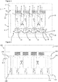
- Figure 1 shows a dewar vessel storage apparatus 1 configured to hold at least two dewar vessels 2.
- dewar vessels 2 are shown which are configured to contain liquefied gas or cryo-compressed gas or slush.
- the gas is hydrogen but it will be appreciated that the apparatus 1 has application for storing dewars of other fluids, such as helium or nitrogen among others.
- the apparatus comprises a box 3 having an outer, thermally insulating, wall 4.
- the box comprising a plurality of insulating cavities 5, each cavity 5 configured to receive a single dewar vessel 2.
- Thermal insulation 6 extends between the cavities 5 to thermally insulate them from each other.
- Each cavity may comprise an elongate bore extending into the box which is surrounded by thermally insulating material.
- Each cavity 5 has an open end through which the dewar vessel 2 is inserted into the cavity and is closed by a separately removable thermally insulating bung 7.
- the dewar vessel 2 within the cavity may be completely surrounded by insulating material.
- an individual cavity can be opened, to remove a dewar vessel for example, without affecting the insulation that surrounds another dewar vessel in a different cavity.
- the apparatus 1 includes a ventilation assembly 8 within the box configured to provide for venting of gas from the dewar vessels 2 when stored in the respective cavities 5 of the storage apparatus 1.
- the ventilation assembly 8, in this example, provides a conduit 10 to each cavity 5 for connection to each dewar vessel 2 which provides a gas outlet flow path from each cavity 5.
- the arrangement of the apparatus and the way of packaging the gas in individual dewars is particularly advantageous as an end user is able to remove one of the dewar vessels without substantially affecting the insulation that surrounds any of the others in the box.
- each dewar vessel may be sized to fit a particular application. Therefore, a user has a ready supply of dewars, thermally insulated in the box, to remove as and when required.
- the gas may be hydrogen and the application may be fuel cell powered autonomous aircraft.
- a user can remove a dewar vessel from the box, load it into the aircraft to act as a fuel source, and launch the aircraft.
- the dewar vessels comprise a removable fuel source or tank for an application.
- a further dewar vessel can be removed from the box and installed as described above.
- the box 3 may be cuboidal although it may be cylindrical. It will be appreciated that the outer wall 4 of the box 3 and any walls interior to the box, such as those separating the cavities, and the bungs 7 may be thermally insulated sufficiently to store a liquefied gas or cryo-compressed gas in a dewer vessel, for at least 1 hour, 5 hours, 10 hours, 12, 24, 72 or more hours without losing more than 10% of the contents due to boil-off (in a 25 deg C ambient environment).
- the outer, thermally insulating, wall may comprise a multi-layer Insulation (MLI) or a super insulation (SI) material inside a high or soft vacuum respectively, a vacuum insulated wall or panel (VIP) or be formed of a plurality of vacuum insulated panels or combination of the above.
- the interior walls may also include MLI, SI or VIP.
- the box 3 may be considered to be a dewar vessel for receiving a plurality of dewar vessels 2.
- the walls 4 or panels may be of metal, such as stainless steel, and include a hollow interior for the vacuum.
- the walls or panels may be infilled with any appropriate insulating material, such as an aerogel, MLI or SI.
- the thermal insulation may reduce or minimize heat transfer from the atmosphere via radiation through the insulation, conduction through the insulation and other heat losses through hydrogen inlet and outlet fittings and conduits.
- Suitable insulation arrangements may comprise a vacuum jacket or panel utilizing a multilayer insulation (MLI) blanket in the vacuum gap; a vacuum jacket or panel with no MLI; a single-walled tank utilizing external spray on foam insulation; and a single-walled tank utilizing aerogel insulation.
- MLI multilayer insulation
- the vacuum jacket or panel with and without a MLI blanket may provide the lightest thermal insulation design solution.
- the cavity 5 may be configured to receive a specific size of dewar vessel and thus may include a head space adjacent the open end of the cavity once the dewar vessel has been received therein.
- the head space may include a wall 11 that is complimentary to an outer surface of the bung 7 such that the bung is sealingly received within the cavity.
- the seal formed between the bung 7 and the cavity 5 may be hermetic.
- the head space wall 11 and/or the bung 7 may include sealing structures, such as seal(s) to seal therebetween.
- the cavities 5 may be substantially cylindrical, cuboidal or any other shape that may be complimentary to the dewar vessel it is configured to receive. Further, the bung may be configured to fit closely adjacent to, such as against, the dewar vessel 2 to reduce the quantity of air surrounding the dewar vessel.
- the bung 7 may fill substantially all of the space around the dewar vessel, which may reduce the quantity of air that may freeze around the outside of the dewar.
- a lower face of the bung may be complimentary to the shape of the base (the end opposite the valves) of the dewar vessel 2.
- the air in the space will cool/liquefy and a partial vacuum may form. If the bung is sealed then it will prevent further air entering the cavity.
- the bung 7 may include a pressure control/relief valve.
- the bung 7 and/or cavity 5 may include conduits, which may terminate in ports, to provide for introduction of a storage fluid within the bunged cavity and around the dewar vessel.
- the storage fluid may be such that it does not condense or freeze in use when subjected to the cold conditions surrounding the dewar vessel 2.
- the conduits may provide for removal of air from the bunged cavity to form a vacuum/partial vacuum around a dewar vessel stored within the cavity.
- the dewar vessel storage apparatus 1 includes a removable lid 12.
- the box 3 includes an aperture 13 configured to provide access to the bungs 7 and cavities 5 and the aperture 7 is closed by the removable lid 12.
- the removable lid 12 may comprise a vacuum insulating panel or may be of an insulating material as described above in relation to the box 3. In other examples, it is not specifically configured to provide for thermal insulation, although by virtue of its material it may have some thermal insulating properties.
- the lid 12 may include an engagement structure, such as a rim or flange, to engage with a complimentary engagement structure on the box 4, such as at the perimeter of the aperture 13.
- the engagement structure may comprise hinges and/or clasps and/or slots to secure the lid in place during use.
- the lid 12 is provided without the bungs 7. Further, the bungs 7 may be configured to close a subset of the cavities.
- the dewar vessels 2 may be of known design and may be configured to hold at least or up to 0.5, 1, 1.5, 2, 2.5, 3, 3.5, 4, 4.5 or 5 kg of hydrogen.
- the dewar vessels 2 may include pressure release valves to release gas therein to relieve the pressure within the vessels as the fluid within the dewar vessel boils off.
- the ventilation assembly 8 of the apparatus 1 is configured to receive said gas so that uncontrolled accumulation of gas within the apparatus 1 is prevented.
- the pressure release valves may form part of a fluid outlet 9 of the dewar vessels 2.
- the ventilation assembly comprises a network of conduits within the box 3 that connect to each cavity 5 and provide a flow path for any gas within the cavities 5 to flow into the network of conduits and (possibly) to atmosphere via a vent 14 that extends through the outer wall 4.
- the ventilation assembly 8 comprises a manifold having a common flow path conduit 16 that has a plurality of branches extending therefrom for connecting to each cavity 5.
- the common flow path conduit 16 connects to the vent 14. It will be appreciated that other network arrangements may be used such as each cavity 5 connecting to a separate conduit that provides a direct vent to atmosphere or elsewhere. Further, it will be appreciated that the vent may not open to atmosphere. Instead, the ventilation assembly 8 may open into a gas storage volume (not shown) for storing the gas from the dewar vessels at a higher temperature.
- the outlet flow path 10 may thus connect to the cavity 5 or may be configured to connect to the dewar 2 within the cavity 5.
- the ventilation assembly 8 includes a plurality of releasable connectors 15, each cavity 5 including a connector for releasably coupling to a dewar vessel.
- the connector 5 may be a standard connector or otherwise compatible with the structure of the inlet/outlet of a dewar vessel 2.
- the releasable connectors 15 are arranged at a base of each cavity 5 such that a connection is made between the dewar vessel 2 and the connector 15 of the ventilation assembly 8 when the dewar vessel 2 is substantially completely inserted into said cavity 5.
- the connectors may be arranged elsewhere in each cavity 2. However, providing the connectors 15 at the base of the cavity is advantageous as the walls of the cavity guide the dewar vessel into engagement with the connector 15.
- vent 14 is to atmosphere
- the ventilation assembly 8 may connect the gas outlet flow path 10 from at least one or all of the cavities 5 to a burner or catalyser or fuel cell for consuming the vented gas (not shown).
- a neck of the dewar vessels 2 includes the pressure relief valves and any other valves required to control the filling and dispensing of fluid from the dewar vessels.
- a sealed connection is made and, on removal, the conduits of the ventilation system may be self-sealing.
- the ventilation assembly 8 includes a controllable valve for controlling the receipt of gas into the gas outlet flow path of at least one or more or all of the cavities or dewars vessels.
- the dewar vessel includes the controllable valve.
- the controllable valve may comprise a solenoid valve.
- the valve or valves may be used to close off the connection to the ventilation assembly 8 for a particular cavity 5 or dewar vessel 2, such as one that does not contain a dewar vessel 2 or due to a fault.
- the ventilation assembly 8 may provide for a vent for each cavity or groups of cavities.
- the apparatus 1 is further configured to provide for filling of the dewar vessels 2 in situ within the box 3.
- the filling of the dewar vessels 2 while loaded in the box 4 may be advantageous as the interior walls/surfaces of the box 3, such as those in closest contact with the dewar vessels 2 can be cooled by the dewar vessels as they are filled.
- the apparatus 1 includes a dewar vessel filling assembly 16 configured to fill, in this example, each of the dewar vessels received within the cavities 5.
- the filling assembly 16 comprises a releasable filling connector configured to releasably couple to a fluid inlet 17 of each dewar vessel 2.
- the connector 15 of the ventilation assembly 8 provides for connection to the fluid inlet 17 of each dewar vessel.
- the connector 15 may have separate flow paths for gas leaving the dewar vessel 2 and gas entering the dewar vessel 2.
- separate connectors are provided for the ventilation assembly and the filling assembly.
- the filling assembly 16 further comprises a fill port 18 for receiving a flow of gas from a source external to the apparatus 1 to fill the dewar vessels.
- the fill port 18 provides a connection to the filling assembly 16 through the outer wall 4 of the box 3.
- An external filling apparatus may connect to the fill port 17.
- the fill port may include a connector part complimentary to connector part on the external filling apparatus.
- a network of conduits, such as a manifold 19, within the box is configured to direct gas from the fill port 17 to the dewar vessels 2 via gas inlet flow paths 20 for each of the cavities that terminate in the connectors 15.
- the manifold 19 includes a control valve 21 for controlling the flow of gas into the filling assembly 16 through the fill port 18.
- the valve 21 may be a solenoid valve or a one-way valve to prevent flow out of the fill port 18.
- the apparatus 1 is configured to circulate gas through the dewar vessels when filling.
- This technique may be advantageous for ensuring that the temperature of the vessels themselves and the filling assembly is sufficiently cold to allow the vessels to be filled to their capacity.
- the filling assembly 16 comprises an inflow section which delivers fluid into each of the dewar vessels 2.
- the dewar vessels 2, in this example, have a divider 22 which separates the fluid inlet 17 from the fluid outlet 9.
- the ventilation assembly connected to the fluid outlet 9, forms an outflow section to receive fluid from the vessels during the filling processes.
- the fluid flows to vent 14 which, during filling, may be connected to the external filling apparatus which may recirculate the gas into the inflow section.
- the filling assembly 16 may have dedicated inflow and outflow sections distinct from the ventilation assembly 8.
- the dewar vessels may be pre-cooled using a coolant such as liquid nitrogen prior to disposing in each cavity of the apparatus 1.
- the external filling apparatus and/or the dewar vessels and/or the apparatus 1 may be provided with suitable authentication mechanisms to prevent tampering and to confirm and authenticate the filling history and ownership of each dewar 2.
- the authentication system may use RFID or other sensors mounted within the apparatus, such as within each cavity.
- the apparatus 1 is configured to be transported easily.
- the apparatus 1 may be configured to be carried by a user.
- the dewar vessel storage apparatus 1 may include a carrying structure (not shown), such as a handle(s) or hand sized indents to allow one or more users to carry the dewar vessel storage apparatus 1.
- the dewar vessel storage apparatus 1 is provided with sufficient insulation or insulation of a particular performance to effectively perform its function providing for storage of dewar vessels during transportation.
- the insulating performance may be such that at least 90% of the contents of the dewar vessels at filling is available at delivery.
- other performance criteria may be used.
- the outer walls of the box may have a thermal performance so as to achieve a thermal input from the surroundings of less than 100W (or less than 80W, or less than 60W, or less than 40W) when at cryogenic temperatures.
- An example size of the dewar vessel storage apparatus may be 1.2 ⁇ 1 ⁇ 1m with an insulation thickness (of at least the outer wall) of at least than 50mm.
- Such a box may contain twelve dewar vessels.
- the heat loss from the box should be controlled by insulation to allow extended storage time of the cryogenic fluid. If a high vacuum MLI insulation is used it may be possible to reduce the heat gain to a few watts. With the correct configuration, storage times could be achieved of at least 12 hours, 1 day or 1 week or more if an active cryo-cooler is used.
- the interior of the box 3, inward of the outer walls, may be substantially thermal insulation 23.
- Figure 2 shows a second example in which a sacrificial gas storage vessel, such as a sacrificial dewar vessel, is provided to assist in maintaining the other dewar vessels 2 within the box at a low temperature.
- a sacrificial gas storage vessel such as a sacrificial dewar vessel
- the one or more sacrificial gas storage vessels 130 and 131 are allowed to expel their contents in a controlled manner such that the cooling effect due to evaporation of the gas out of the sacrificial gas storage vessels can be used to cool the "normal" dewar vessels 102.
- the sacrificial dewar vessels 130, 131 may be located adjacent the outer wall 4 or outwards of the other dewar vessels 2.
- the pressure in the sacrificial dewar vessels may be lower than the others.
- the dewar vessel storage apparatus 101 further includes a thermally conductive element 132 that surrounds the sacrificial gas storage vessels 130, 131 (or the cavity within which they are located) as well as at least one of other dewar vessels 102.
- a single thermally conductive element 132 surrounds all of the cavities 105 and the sacrificial gas storage vessels 130, 131.
- the thermally conductive element 132 may be of metal, such as aluminium.
- the thermally conductive element provides for transfer of heat between the dewar vessels 102 and the sacrificial gas storage vessels 130, 131.
- the sacrificial dewar vessels 130, 131 are non-removable and thus fixed within the thermally conductive element 132 and connect to the ventilation assembly 108 and filling assembly 116.
- the sacrificial gas storage vessels 130, 131 may be removable.
- the apparatus 101 may include "sacrificial" cavities designated to receive the sacrificial dewar vessels 131, 132.
- the "sacrificial" cavities may be substantially the same as the other cavities. They may differ in that the ventilation assembly 108 may be configured differently to receive the sacrificial gas vented from the sacrificial dewar vessels.
- the connector 115 or an element associated with the connector within a sacrificial cavity may provide for release of the gas within the sacrificial gas storage vessel at a particular predetermined rate.
- the ventilation assembly 16 may include means to actively control the release of gas from the sacrificial gas storage vessel(s) 130, 131, which may be in response to a sensor input, such as a temperature sensor.
- the apparatus 101 may be configured or the sacrificial dewar vessel may be configured to continuously or intermittently vent its contents over a predetermined time period.
- the predetermined time period may be selected to exhaust its entire contents over an intended use period. For example, if the dewar storage apparatus is configured to transport the dewars over a 5 hour journey, the predetermined time may be 5 hours or based on the expected journey time or based on a "rating" of the dewar storage apparatus.
- thermally conductive element 132 for providing heat transfer between the dewar vessels 102 and the sacrificial dewar vessels 130, 132 comprises a block in this example, in other examples, it may comprises one or more heat pipes or a refrigeration or cryogenic cooling system.
- the refrigeration/cryogenic cooling system may include a compressor, condenser and a working fluid that is cooled by the sacrificial gas storage vessel(s).
- the sacrificial gas storage vessels are dewar vessels 130, 131 similar to the "normal" dewar vessels 102, as they are adapted to hold the same liquefied or cryo-compressed gas or slush.
- the vessels 102, 130 are all connected to the filling assembly 116 and are configured to be filled together.
- the gas is circulated through the vessels 102, 130 using the ventilation assembly 108 as an outflow section.
- the external filling apparatus (not shown) may be disconnected from the fill port 118 and vent port 114 and the apparatus 101 may be ready for transport or storage of the dewar vessels 2.
- the pressure relief valve of the sacrificial dewar vessels 130, 131 is configured at a lower pressure than the "normal" dewar vessels.
- the pressure relief valves may be set to the same value, but by virtue of locating the sacrificial dewar vessels adjacent an outer wall, they may release their gas quicker than the other dewar vessels.
- the apparatus 101 is configured to control the rate at which the gas is released from the sacrificial dewar vessels 130, 131.
- Figures 3 and 4 show third and fourth example of the dewar vessel storage apparatus.
- the same reference numerals have been used for like features except that "200" has been added to them for Figure 3 and "300” has been added to them for Figure 4 .
- a thermally conductive element 232, 332 is provided within the box 203, 303.
- the thermally conductive element is spaced inwardly of the outer walls 204, 304 such that it is thermally isolated from the exterior of the box.
- the thermally conductive element comprises a thermal mass of aluminium. A high thermal mass may advantageously control temperature fluctuations.
- the thermally conductive element 232, 332 includes a heat exchanger 240, 340.
- the heat exchanger is provided in direct or indirect thermal contact, such as via the thermally conductive element 232, 332, with the dewar vessels 202, 302.
- the heat exchanger 240, 340 is configured to receive a working fluid, comprising a suitable refrigerant/cryogenic working fluid, which is cooled using a cryo-cooling apparatus 241, 341.
- the cryo-cooling apparatus 241, 341 is external to the box 203, 303, although it may be integrated therein.
- the cryo-cooling apparatus 241, 341 receives a supply of power for cryo-cooling the refrigerant/cryogenic working fluid for supply to the heat exchanger.
- FIG. 4 differs from that shown in Figure 3 in that an electrochemical fuel cell 342 is provided to generate, at least in part, the electrical power required by a refrigeration system, such as cryo-cooling apparatus 341.
- the fuel cell 342 is arranged to use, as its fuel, the hydrogen that is vented from the ventilation assembly 308.
- a conduit 343 is provided to direct the hydrogen gas leaving the vent 314 to an anode of the fuel cell 342.
- a cathode of the fuel cell 342 is configured to consume oxygen from atmospheric air as its oxidant. This arrangement may be advantageous as an increase in the gas leaving the ventilation assembly 308 may be indicative of the temperature in the apparatus 301 rising.
- a closed loop feedback loop is provided by the ventilation assembly 308, the conduit 343, the fuel cell 342, the cryo-cooling apparatus 341 and the heat exchanger 340.
- a sacrificial dewer vessel which may provide the gas/hydrogen to power the fuel cell 342.
- the fuel cell 342 may be configured to use the gas vented from the one or more dewar vessels to generate electricity for a different purpose, such as for sensors to monitor the temperature of the apparatus 1.
- the heat exchanger 340 and cryo-compressor 341 may not be present.
- the fuel cell 342 may be used to power a display or a user interface disposed on the dewar vessel storage apparatus or any other load.
- the fuel cell 342 may power circuitry to determine at least one operating parameter of one or more of the dewar vessels and may store the data which is representative of the at least one operating parameter of the dewar in a memory device located on the dewar or as part of the apparatus for display or recording.
- the fuel cell 342 may be configured to provide said electricity to one or more of; a telemetry assembly configured to measure a property of the apparatus or a dewar vessel therein for sending to a remote device; a geolocation determination element configured to determine the location of the apparatus; a clock; a user-input element for receiving user input, such as to access the dewar vessels in the apparatus; a tamper detection element configured to determine if the apparatus is being or has been tampered with; a communication element configured to provide for communication between the apparatus and a remote device; a temperature sensor configured to monitor an internal or external temperature of apparatus; and a transaction element configured to provide for the logging of the removal of a dewar vessel as an energy transfer transaction.
- the dewar storage apparatus may include a thermal mass element configured to surround one or more of the cavities 5.
- the thermal mass may be cooled to a temperature, such as during filling of the dewar vessels in situ, that assists in maintaining the dewar vessels 2 at a desired temperature.
- the thermal mass element may have an isobaric volumetric heat capacity of greater than 2 J.cm -3 .K -1 .
- the filling assembly a particular layout of the ventilation assembly, a particular layout to provide a sacrificial gas storage vessel, the thermal mass element, the heat exchanger, the number and layout of the cavities, the refrigeration/cryogenic cooling system and/or the fuel cell, at least, may be provided in any combination.
- Figure 5 shows a flow chart illustrating the method of providing a dewar vessel storage apparatus as described above 500; providing a plurality of dewar vessels for receiving the liquefied or cryo-compressed gas/slush 501; transporting the dewar vessel storage apparatus having the plurality of dewar vessels stored therein to the point of use 502; and the dewar vessel storage apparatus providing for individual removal of one of the plurality of dewar vessels at the point of use 503 without disturbing the insulation provided for another of the dewar vessels.
- Figure 6 shows a storage apparatus 601 for one or more gas storage vessels which, in this example comprise dewar vessels, although they may comprise single skinned vessels.
- the apparatus 601 is substantially similar to that shown in figure 1 and reference numerals with the addition of "600" are used to designate like parts.
- the apparatus 601 includes a communication element 660 configured to provide signalling to a remote device 661 (via wireless communication for example).
- the signalling is indicative of the availability and/or consumption of said gas stored in the dewar vessels 602 within the apparatus 601.
- the communication element 660 is used for security or safety reasons, as will be described below.
- the remote device 661 may comprise a server configured to monitor the one or more of the apparatuses 601 and optionally provide for the billing of users of the apparatus for use of the gas contained therein based on the signalling received from apparatus 601.
- the server 661 may control the dispatch of another storage apparatus 601 if the quantity of gas or rate of usage of gas in the current storage apparatus 601 exceeds a threshold.
- the apparatus 601 in this example further includes a geolocation element 662, which may comprise a GPS or other satellite geolocation receiver or a land-based geolocation determination element.
- the location of the apparatus 601 may be provided for communication by communication element 660.
- the billing of the user for the consumption of gas may use the geolocation information.
- the geolocation information may be used for security purposes as explained below.
- a proximity or other type of sensor 663 is provided associated with each cavity (although only one is shown in Figure 6 for simplicity) to detect whether or not the dewar vessel in the cavity has been removed.
- the sensor 663 may be in communication with the communication element 660, which may, on detection of the removal of the dewar vessel, provide signalling to the remote device for billing, accounting or security purposes.
- the sensor 663 comprises a dewar vessel contents measurement sensor, which may use ultrasonic pulses to determine the quantity of gas within the dewar vessel, which may be communicated to the communication element 660 for billing, accounting, safety/performance monitoring or security purposes.
- each cavity 605 is provided with a locking mechanism 664, although only one is shown for simplicity.
- the locking mechanism is configured to engage with a dewar vessel 602 and, when in a locked state, prevent removal of a dewar vessel 602 from its cavity 605 and, in an unlocked state, allow for removal of said dewar vessel 602.
- the locking mechanism includes a retractable bolt 665 to physically engage a complimentary indentation of the vessel 602.
- the locking mechanism provides a magnetic engagement with a dewar vessel, which may operate through the insulation of cavity.
- the locking mechanism may engage with the bung 607. Access to the base of the cavity where the locking mechanism is located is via the cavity. Thus, when a dewar vessel 602 is mounted therein, user access to the locking mechanism is restricted, which may prevent tampering.
- a locking mechanism controller 672 is provided to control the locking mechanisms 664 of each of the cavities.
- the controller 672 is configured to receive user input from a user-input element 666, such as a keypad or biometric sensor.
- a user-input element 666 such as a keypad or biometric sensor.
- the locking mechanism controller 672 may switch one or more of the locking mechanism 664 to the locked or unlocked state.
- the locking mechanism controller 672 is connected to the communication element 660, which may provide for remote control of the locking mechanism.
- the locking mechanism controller 672 may be programmable to lock or unlock in the dewar vessels 602 in accordance with certain criteria.
- locking mechanism controller 672 may programmable with a lock profile, which defines at least one of;
- Figure 6 also show the inclusion of a dilution gas element 667.
- a ventilation assembly 608 may be provided to receive any gas exhausted from the dewar vessels 602.
- the gas may be a flammable gas, such as hydrogen, and the dilution gas element is configured to ensure that the concentration of the gas at the outlet 614 does not exceed a predetermined threshold, such as one based on the flammability limit of the gas.
- the dilution gas element 667 comprises a pump that receives atmospheric air at 668 to maintain a suitable concentration.
- a dilution gas source may be stored within the apparatus 601.
- the pump 667 receives a signal from a gas flow rate sensor 669 mounted in the ventilation assembly 608.
- the sensor 669 may control the exhaustion rate from the dilution gas source.
- the apparatus 601 may include an evacuation element 670 configured to provide for the controlled release of the contents of one or more of the dewar vessels 602 within the apparatus 601, on receipt of an evacuation signal.
- the evacuation signal may be provided for safety reasons based on the temperature of the apparatus 601 from a temperature sensor 672.
- the temperature sensor 672 is configured to measure the external temperature of the apparatus 601 but may alternatively or additionally measure the temperature inside the apparatus 601.
- the evacuation signal may be received from a tamper detection element 670 or from the remote device 661 via the communication element 660. Thus, if the internal or external temperature of the apparatus, or a change in the temperature is above a threshold, the evacuation element may be actuated.
- the tamper detection element 670 may be configured to detect unauthorised removal or attempted removal of a dewar vessel from the apparatus. Thus, the tamper detection element 670 may receive data from the locking mechanism 664 and/or the sensors 663. The unauthorised removal may be deemed unauthorised based on a time of removal or attempted removal. A location, received from the element 662, at the time of removal or attempted removal, may be used to determine whether the removal is unauthorised. Unaccepted authorisation details provided via the input element 666 may result in generation of the evacuation signal. Further, the tamper detection element 670 may detect movement of the box above a threshold or use integrity sensors to determine damage to the apparatus 601.
- the evacuation element 670 may be configured to act on signalling received (wirelessly for example) from a remote device 661 via the communication element 660.
- the evacuation element may be configured to control the flow rate of gas leaving the apparatus from dewar vessels and/or its concentration.
- the evacuation element 670 is connected to a plurality of actuators of the ventilation assembly 608 that are each associated with one of the cavities 605.
- the actuators (not shown) are configured to actuate the pressure relief valve of the dewar vessel 602 such that it evacuates its contents through the ventilation assembly 608.
- each storage apparatus 601 provides means for the formation of a gas distribution system 675 comprising one or more dewar vessel storage apparatuses 601 and at least one remote device 661.
- the remote device 661 may comprise a centralised or distributed server configured to maintain a record of the availability and/or consumption of said gas stored in the dewar vessels of the one or more dewar vessel storage apparatus.
- the remote device may provide signalling via the communication element 660 to control the locking mechanism 664, the evacuation element 670 or other functionality of the apparatus 601.
- the remote device 661 may be configured to use said record to provide for billing of users of the dewar vessel storage apparatuses based on the gas consumption.
- the remote device 661 is configured to maintain the record using block chain technology and may thus be associated with miners and any other apparatus required to implement the block chain.
- the communication element 660 may be used to provide for exchange or transfer of dewar vessel(s) 602 to the storage apparatus of other users. Therefore, if a user is low on gas in their storage apparatus, they may identify and find another user with which to perform a transaction.
- the apparatus 601 is configured to send the remote device 661 an energy-availability messages indicating that gas is available for transfer to other users or to other dewar vessel storage apparatuses.
- the message may include a geographic location from element 662.
- the remote device 661 may then maintain a database of this information that can be viewed by other apparatus 601 users or may be configured to send a message to other dewar vessel storage apparatus (or at least ones that have indicated a demand for gas via a message) comprising the offer of the availability of gas from the first apparatus.
- the remote device 661 may not be a server and may be a further, different dewar vessel storage apparatus.
- the apparatus 601 with their respective communication elements 660 form a peer-to-peer arrangement.
- the provision of gas sharing/exchange/transactions may be achieved by transmission of messages between apparatuses (or a central server).
- the distributed nature of the apparatuses 601, 661 may provide for distributed storage of a gas availability/consumption ledger, such as a distributed database or block chain, to account for energy availability and/or consumption from each apparatus 601, 661.
Landscapes
- Engineering & Computer Science (AREA)
- Mechanical Engineering (AREA)
- General Engineering & Computer Science (AREA)
- Physics & Mathematics (AREA)
- Thermal Sciences (AREA)
- Filling Or Discharging Of Gas Storage Vessels (AREA)
Claims (15)
- Dewargefäßlagereinrichtung (1), die dazu konfiguriert ist, mindestens zwei Dewargefäße (2) zu enthalten, die Flüssiggas oder kryokomprimiertes Gas beinhalten, die umfasst:eine Box (3), die eine äußere thermisch isolierende Wand (4) aufweist;wobei die Box (3) eine Vielzahl isolierender Hohlräume (5) umfasst, wobei jeder Hohlraum dazu konfiguriert ist, ein einziges Dewargefäß (2) aufzunehmen und thermisch von jedem anderen Hohlraum (5) isoliert ist;
wobei jeder Hohlraum einen separat abnehmbaren thermisch isolierenden Spund (7) beinhaltet, der dazu konfiguriert ist, ein offenes Ende seines Hohlraums zu schließen;wobei eine Belüftungsanordnung (8) mindestens eine Leitung (10) innerhalb der Box umfasst, die dazu konfiguriert ist, Gas, das von den Dewargefäßen (2) freigegeben wird, wenn sie in den jeweiligen Hohlräumen (5) der Box gelagert werden, zu entlüften, wobei die Belüftungsanordnung dazu konfiguriert ist, einen Gasausslassströmungsweg von jedem Hohlraum bereitzustellen,wobei die Belüftungsanordnung (8) einen freigebbaren Steckverbinder (15) beinhaltet, der dazu konfiguriert ist, den Auslassströmungsweg eines der Hohlräume (5) mit einem Druckentlastungsventil eines Dewargefäßes (2) zu verbinden, das in einen der Hohlräume (5) eingefügt ist, um verdampftes Gas von dem Dewargefäß zu empfangen,wobei der freigebbare Steckverbinder (15) an einer Basis des Hohlraums (5) derart eingerichtet ist, dass eine Verbindung zwischen dem Dewargefäß und der Belüftungsanordnung (10) hergestellt wird, wenn das Dewargefäß (2) im Wesentlichen vollständig in den Hohlraum (5) eingesetzt ist,wobei jeder Hohlraum (5) und sein assoziierter Spund (7) komplementär zu der Form des Dewargefäßes (2) konfiguriert ist, konfiguriert ist, derart aufzunehmen, dass im Wesentlichen kein Luftraum besteht, wenn das Dewargefäß (2) in dem Hohlraum (5) aufgenommen ist und der Spund (7) an Ort und Stelle ist. - Dewargefäßlagereinrichtung (1) nach Anspruch 1, wobei die äußere thermisch isolierende (4) Wand und/oder Isolation zwischen jedem Hohlraum mindestens eine umfasst; einer vakuumisolierten Platte, die einen mehrschichtigen Isolationsmantel in dem Vakuumspalt einsetzt; eine Vakuumhülle oder Platte ohne mehrschichtigen Isolationsmantel in dem Vakuumspalt; eine Wand, die Sprüh- oder Schaumisolation einsetzt; und eine Wand, in die Aerogelisolation eingebaut ist,
wobei die Außenwände der Box (3) eine Wärmeleistung derart aufweisen können, dass sie eine Wärmeeingabe von der Umgebung von weniger als 100 Watt erreichen, wenn sie ein kryogenes Dewargefäß enthalten. - Dewargefäßlagereinrichtung (1) nach einem vorstehenden Anspruch, wobei die Belüftungsanordnung (8) einen Rohrverteiler umfasst, der dazu konfiguriert ist, jeden Hohlraum (5) zu verbinden und einen gemeinsamen Belüftungsströmungsweg (16) bereitzustellen, wobei der Rohrverteiler den Auslassströmungsweg von jedem Hohlraum bereitstellt.
- Dewargefäßlagereinrichtung (1) nach einem vorstehenden Anspruch, wobei die Belüftungsanordnung (8) ein steuerbares Ventil zum Steuern der Aufnahme von Gas in den Gasauslassströmungsweg (10) mindestens einer oder mehrerer oder aller Hohlräume (5) beinhaltet, und die Belüftungsanordnung dazu konfiguriert ist;den Gasauslassströmungsweg (10) von mindestens einem der Hohlräume (5) mit der Umgebung zu verbinden;und/oder den Gasauslassströmungsweg (10) von mindestens einem der Hohlräume mit einem Brenner oder Katalysator zum Verbrauchen des entlüften Gases zu verbinden; und/oder den Gasauslassströmungsweg (10) von mindestens einem der Hohlräume mit einer elektrochemischen Brennstoffzelle zu verbinden, wobei die Brennstoffzelle dazu konfiguriert ist, Gas zu verwenden, das aus dem einen oder den mehreren Dewargefäß (2) entlüftet wird, um Elektrizität zu erzeugen; den Gasauslassströmungsweg (10) von mindestens einem der Hohlräume (5) mit einem Gasspeicher zu verbinden.
- Dewargefäßlagereinrichtung (1) nach einem vorstehenden Anspruch, die ein Kälte- oder kryogenes Kühlsystem (341) beinhaltet, das dazu konfiguriert ist, ein Inneres der Box (303) zu kühlen,
wobei das Kälte- oder kryogene Kühlsystem mindestens von Gas, das aus dem (den) Dewargefäß(en), das (die) innerhalb der Hohlräume enthalten ist (sind), mit Leistung versorgt wird. - Dewargefäßlagereinrichtung (101) nach einem vorstehenden Anspruch, die weiter ein Opfergaslagergefäß (130, 131) und ein Wärmetransferelement (132) umfasst;wobei die Box dazu konfiguriert ist, das Opfergaslagergefäß in einem Opferhohlraum unterzubringen;wobei das Opfergaslagergefäß (130, 131) dazu konfiguriert ist, kontinuierlich oder intermittierend seinen Inhalt über eine vorbestimmte Zeitspanne zu entlüften und daher seine Temperatur zu senken;wobei die Box dazu konfiguriert ist, Verbindung des Opfergaslagergefäßes mit einem Auslass zu versehen, um das Gas, das daraus freigesetzt wird, aufzunehmen;wobei das Wärmetransferelement (132) dazu konfiguriert ist, ein Inneres der Box und/oder die Hohlräume (102) unter Verwenden der gesenkten Temperatur des Opferhohlraums zu kühlen;wobei das Opfergaslagergefäß (130, 131) ein Druckentlastungsventil beinhaltet, um Entlüften seines Inhalts bereitzustellen, und das Druckentlastungsventil an einem niedrigeren Druck zu jedem anderen Dewargefäß (102), das von der Einrichtung aufgenommen wird, konfiguriert ist, undwobei das Wärmetransferelement (132) mindestens eines umfasst von;einem oder mehreren Heizrohren;einem Kältesystem;einem kryogenen Kühlsystem; undeiner thermischen Masse, die einen ersten Teil umfasst, der sich um das Opferdewargefäß erstreckt, und einen zweiten Teil, der sich um mindestens einen der Hohlräume erstreckt, wobei der erste Teil thermisch mit dem zweiten Teil verbunden ist, um zwischen den Teilen Wärmetransfer bereitzustellen.
- Dewargefäßlagereinrichtung (1) nach einem vorstehenden Anspruch, das eine Dewargefäßfüllanordnung (16) innerhalb der Box (3) umfasst und dazu konfiguriert ist, ein oder mehrere Dewargefäße (2), die innerhalb der Hohlräume (5) aufgenommen sind, zu füllen, wobei die Füllanordnung einen freigebbaren Füllsteckverbinder (15) umfasst, der dazu konfiguriert ist, mit einem Dewargefäß (2), das in einen der Hohlräume eingesetzt ist, und einem Füllanschluss (18) freigebbar zu koppeln, um eine Gasströmung aufzunehmen, um das Dewargefäß zu füllen, wobei die Anordnung dazu konfiguriert ist, Gas von dem Füllanschluss (18) zu dem Dewargefäß (2), das mit dem Steckverbinder (15) verbunden ist, zu lenken.
- Dewargefäßlagereinrichtung (1) nach Anspruch 7, wobei die Dewargefäßfüllanordnung (16) dazu konfiguriert ist, Gas durch das (die) Dewargefäß(e) (2) umzuwälzen, wenn das (die) Dewargefäß(e) gefüllt wird (werden), wobei die Füllanordnung (16) eine Umwälzschleife umfasst, die einen Einströmungsteilabschnitt aufweist, der den Füllanschluss (18) und den Füllsteckverbinder (15) beinhaltet, um das Gas aufzunehmen und zu dem oder jedem Dewargefäß zu lenken, das innerhalb eines jeweiligen Hohlraums aufgenommen ist, und einen Ausströmungsteilabschnitt, um das Gas von dem oder jedem Dewargefäß innerhalb eines jeweiligen Hohlraums aufzunehmen, um es zu dem Einströmungsteilabschnitt zurück umzuwälzen,
wobei die Belüftungsanordnung (8) mindestens einen Teil des Ausströmungsteilabschnitts bildet, wenn das oder die Dewargefäß(e) 2 gefüllt werden. - Dewargefäßlagereinrichtung (1) nach einem vorstehenden Anspruch, wobei eine thermische Masse dazu konfiguriert ist, sich um den mindestens einen der Hohlräume zu erstrecken, wobei die thermische Masse ein thermisch leitendes Material bezüglich der Isolation der Außenwand umfasst und von der Außenwand umgeben ist, wobei die thermische Masse eine isobare volumetrische Wärmekapazität von mehr als 2 J.cm-3K-1-1 aufweist.
- Dewargefäßlagereinrichtung (601) nach einem vorstehenden Anspruch, wobei mindestens einer der Hohlräume (605) der Dewargefäßlagereinrichtung einen Verriegelungsmechanismus (664) beinhaltet, der dazu konfiguriert ist, in einem verriegelten Zustand das Herausnehmen eines Dewargefäßes (602), das sich innerhalb des Hohlraums befindet, zu verhindern und das Herausnehmen in einem entriegelten Zustand des Abnehmen des Dewargefäßes zu erlauben,wobei das Dewargefäßlagereinrichtung eine Verriegelungsmechanismussteuereinheit (672) beinhaltet, die dazu konfiguriert ist, Umschalten des oder jedes Verriegelungsmechanismus (664) zwischen einem verriegelten und entriegelten Zustand bereitzustellen, basierend auf einem oder mehrereneines Benutzereingabeelements (662), wie einem Tastenfeld oder biometrischen Sensor;Signalisieren von einer entfernten Vorrichtung,wobei der Verriegelungsmechanismus (664) oder die Verriegelungsmechanismussteuereinheit (672) mit einem Verriegelungsprofil programmierbar ist, das mindestens eines definiert;der Zeit, während der einer oder mehrere der Verriegelungsmechanismen in einen verriegelten oder entriegelten Zustand gesetzt sind;der geographischen Lage, an der die Verriegelungsmechanismen in einen verriegelten oder entriegelten Zustand gesetzt sind;dem Zustand des einen oder der mehreren Verriegelungsmechanismen (664) basierend auf der Anwesenheit oder Abwesenheit eines Dewargefäßes (602) in einem der anderen Hohlräume (605), um Steuerung der Anzahl von Dewargefäßen, die in einem Zeitpunkt herausgenommen werden können, bereitzustellen; Benutzerauthentifizierungseinzelheiten, wie ein Zugangspasswort oder biometrische Informationen, die erforderlich sind, um einen oder mehrere der Verriegelungsmechanismen (664) zwischen dem verriegelten und dem entriegelten Zustand umzuschalten.
- Dewargefäßlagereinrichtung (601) nach einem vorstehenden Anspruch, wobei die Einrichtung ein Verdünnungsgaselement (667) umfasst, das dazu konfiguriert ist, ein Verdünnungsgas mit einem Gas, das aus den Dewargefäßen ausgestoßen wird, durch die Belüftungsanordnung bereitzustellen,wobei das Verdünnungsgaselement (667) umfasst;ein Verdünnungsgaslagergefäß, das dazu konfiguriert ist, seinen Inhalt auszustoßen, um Gase, die die Belüftungsanordnung (608) verlassen, zu verdünnen; odereine Pumpe (667), die dazu konfiguriert ist, einen Strom atmosphärischer Luft als das Verdünnungsgas bereitzustellen,wobei der Verdünnungsgasstrom basierend auf einem Gaskonzentrationssensor und/oder einem Gasströmungsratensensor (669) der Einrichtung gesteuert ist.
- Dewargefäßlagereinrichtung (601) nach einem vorstehenden Anspruch, wobei die Einrichtung ein Ableitungselement (670) beinhaltet, das dazu konfiguriert ist, die gesteuerte Freigabe des Inhalts eines oder mehrerer der Dewargefäße (602) innerhalb der Einrichtung bei Empfang eines Ableitungssignals bereitzustellen,
wobei das Ableitungssignal von einem oder mehreren bereitgestellt wird;eines Manipulationserkennungselements (670);eines Temperatursensors (672);einer entfernten Vorrichtung (661) über ein Kommunikationselement (660). - Dewargefäßlagereinrichtung (601) nach einem vorstehenden Anspruch, wobei die Einrichtung ein Kommunikationselement (660) beinhaltet, das dazu konfiguriert ist, Kommunikation mit einer entfernten Vorrichtung (661) bereitzustellen, wobei die Einrichtung dazu konfiguriert ist, das Kommunikationselement (660) zu verwenden, um;Signalisierung zu der entfernten Vorrichtung (661) bereitzustellen, die Gasverbrauch oder Gasverfügbarkeit angibt, wie eine Gasmenge, die in den Dewargefäßen (602) enthalten ist, und/oder die Anzahl von Dewargefäßen, die aus der Einrichtung herausgenommen oder verwendet wurden oder die in der Einrichtung verbleiben,wobei das Kommunikationselement (660) dazu konfiguriert ist, basierend auf einer Messung der Gasmenge, die in den Dewargefäßen der Einrichtung enthalten ist, und einer Geolokalisierung der Einrichtung Signalisierung zu einer oder mehreren entfernten Vorrichtungen (661) bereitzustellen, um anzugeben, dass ein oder mehrere Dewargefäße zum Bereitstellen zu einem anderen Benutzer verfügbar sind, und die Lage anzugeben.
- Dewargefäßlagereinrichtung nach einem vorstehenden Anspruch, wobei die Einrichtung eine elektronische Brennstoffzelle (342) beinhaltet, die dazu konfiguriert ist, mindestens Gas, das aus dem einen oder den mehreren Dewargefäßen entlüftet wird, zu verwenden, um Elektrizität zu erzeugen, wobei die elektrochemische Brennstoffzelle (342) dazu konfiguriert ist, die Elektrizität zu einem oder mehreren bereitzustellen;einer Telemetrieanordnung, die dazu konfiguriert ist, eine Eigenschaft der Einrichtung oder eines Dewargefäßes darin zu messen, um zu einer entfernten Vorrichtung zu senden;ein Geolokalisierungsbestimmungselement, das dazu konfiguriert ist, die Lage der Einrichtung zu bestimmen;eine Uhr;ein Benutzereingabeelement zum Empfangen von Benutzereingabe, wie zum Zugreifen auf die Dewargefäße in der Einrichtung;ein Manipulationserkennungselement, das dazu konfiguriert ist zu bestimmen, ob an dem Gerät manipuliert wird oder wurde;ein Kommunikationselement, das dazu konfiguriert ist, Kommunikation zwischen der Einrichtung und einer entfernten Vorrichtung bereitzustellen;einen Temperatursensor, der dazu konfiguriert ist, eine innere oder äußere Temperatur der Einrichtung zu überwachen; undein Transaktionselement, das dazu konfiguriert ist, das Herausnehmen eines Dewargefäßes als eine Energietransfertransaktion zu protokollieren.
- Verfahren zum Bereitstellen eines Flüssiggases oder kryokomprimierten Gases oder Schlamms zu einer Verwendungsstelle, das umfasst;Bereitstellen einer Dewargefäßlagereinrichtung (1), wie in einem vorstehenden Anspruch definiert;Bereitstellen einer Vielzahl von Dewargefäßen (2) zum Aufnehmen von Flüssiggas oder kryokomprimiertem Gas oder Schlamm;Füllen der Vielzahl von Dewargefäßen (2), während sie innerhalb der Dewargefäßlagereinrichtung (1) gelagert sind, wobei der Schritt des Fühlens das Umwälzen von Gas durch die Dewargefäße beinhaltet;Transportieren der Dewargefäßlagereinrichtung (1), die die Vielzahl von Dewargefäßen darin gelagert aufweist, zu dem Verwendungsort; undHerausnehmen eines der Vielzahl von Dewargefäßen (2) an dem Verwendungsort.
Applications Claiming Priority (3)
| Application Number | Priority Date | Filing Date | Title |
|---|---|---|---|
| GB1515344.8A GB2541734B (en) | 2015-08-28 | 2015-08-28 | Dewar vessel storage apparatus |
| GB1516763.8A GB2541752A (en) | 2015-08-28 | 2015-09-22 | Dewar vessel storage apparatus |
| PCT/GB2016/052645 WO2017037429A2 (en) | 2015-08-28 | 2016-08-25 | Dewar vessel storage apparatus |
Publications (2)
| Publication Number | Publication Date |
|---|---|
| EP3341645A2 EP3341645A2 (de) | 2018-07-04 |
| EP3341645B1 true EP3341645B1 (de) | 2021-10-20 |
Family
ID=54326504
Family Applications (1)
| Application Number | Title | Priority Date | Filing Date |
|---|---|---|---|
| EP16775815.0A Active EP3341645B1 (de) | 2015-08-28 | 2016-08-25 | Dewar-gefäss-aufbewahrungsvorrichtung |
Country Status (4)
| Country | Link |
|---|---|
| US (1) | US11137116B2 (de) |
| EP (1) | EP3341645B1 (de) |
| GB (2) | GB2541734B (de) |
| WO (1) | WO2017037429A2 (de) |
Cited By (1)
| Publication number | Priority date | Publication date | Assignee | Title |
|---|---|---|---|---|
| EP4417863A1 (de) * | 2023-02-20 | 2024-08-21 | MAGNA Energy Storage Systems GesmbH | Kryotankvorrichtung mit einem boil-off-managementsystem |
Families Citing this family (11)
| Publication number | Priority date | Publication date | Assignee | Title |
|---|---|---|---|---|
| EP3663631B1 (de) * | 2017-07-31 | 2023-10-11 | Atomis Inc. | Gaslagerungsbehälter |
| CN114761726B (zh) * | 2019-12-02 | 2024-05-24 | 法国全耐塑料新能源公司 | 用于交通工具的加压流体储存和分配组件 |
| FR3103875B1 (fr) * | 2019-12-02 | 2024-08-02 | Plastic Omnium Advanced Innovation & Res | Ensemble de stockage et de distribution de fluide sous pression pour véhicule |
| US12379071B2 (en) * | 2020-07-22 | 2025-08-05 | Cryoport, Inc. | Dewar drying device |
| JP1687860S (de) | 2020-10-15 | 2021-06-14 | ||
| EP4274983B1 (de) * | 2021-01-06 | 2026-04-15 | Verne Inc. | Kryokomprimierte wasserstoffspeicher-mehrtanksysteme und deren wärmeverwaltung |
| DE102021202900A1 (de) * | 2021-03-24 | 2022-09-29 | Magna Steyr Fahrzeugtechnik Ag & Co Kg | Flüssigwasserstoffspeicher |
| CN113464836B (zh) * | 2021-07-07 | 2022-09-06 | 广州市粤佳气体有限公司 | 一种低温液态气体杜瓦罐全自动供应工艺 |
| DE102021207187A1 (de) * | 2021-07-08 | 2023-01-12 | Robert Bosch Gesellschaft mit beschränkter Haftung | Tankvorrichtung zur Speicherung eines gasförmigen Mediums |
| CN114623369A (zh) * | 2022-01-21 | 2022-06-14 | 北京航天发射技术研究所 | 气源系统 |
| CN114673927B (zh) * | 2022-04-09 | 2024-09-20 | 深圳市宏智智能装备有限公司 | 一种定向识别联动自锁信息化供气系统的控制方法 |
Family Cites Families (8)
| Publication number | Priority date | Publication date | Assignee | Title |
|---|---|---|---|---|
| US2075408A (en) * | 1935-09-17 | 1937-03-30 | Ohio Chemical And Mfg Company | Transfer of liquefied gas |
| US3319433A (en) * | 1966-05-24 | 1967-05-16 | Ryan Ind Inc | Rectangular dewar |
| US8079408B2 (en) * | 2003-09-22 | 2011-12-20 | Bosch Rexroth Corporation | Pressure vessel assembly for integrated pressurized fluid system |
| FR2874247B1 (fr) * | 2004-08-12 | 2007-03-16 | Air Liquide | Systeme stockage de gaz, procede de mise en oeuvre et vehicule incorporant un tel systeme |
| WO2007072470A1 (en) * | 2005-12-22 | 2007-06-28 | C. En. Limited | Apparatus and cartridge for storage of compressed hydrogen gas and system for filling the cartridge |
| US9562646B2 (en) * | 2013-07-12 | 2017-02-07 | Ut-Battelle, Llc | Hydrogen storage container |
| CN103615655A (zh) * | 2013-11-15 | 2014-03-05 | 张家港保税区长江新能源装备有限公司 | 一种低温绝热气瓶抽真空系统 |
| CN105605414A (zh) * | 2016-03-08 | 2016-05-25 | 位旭 | 一种智能防爆液化气罐 |
-
2015
- 2015-08-28 GB GB1515344.8A patent/GB2541734B/en active Active
- 2015-09-22 GB GB1516763.8A patent/GB2541752A/en not_active Withdrawn
-
2016
- 2016-08-25 EP EP16775815.0A patent/EP3341645B1/de active Active
- 2016-08-25 US US15/756,520 patent/US11137116B2/en active Active
- 2016-08-25 WO PCT/GB2016/052645 patent/WO2017037429A2/en not_active Ceased
Cited By (1)
| Publication number | Priority date | Publication date | Assignee | Title |
|---|---|---|---|---|
| EP4417863A1 (de) * | 2023-02-20 | 2024-08-21 | MAGNA Energy Storage Systems GesmbH | Kryotankvorrichtung mit einem boil-off-managementsystem |
Also Published As
| Publication number | Publication date |
|---|---|
| EP3341645A2 (de) | 2018-07-04 |
| US20200224825A1 (en) | 2020-07-16 |
| GB2541734A (en) | 2017-03-01 |
| GB2541734B (en) | 2021-09-01 |
| GB201516763D0 (en) | 2015-11-04 |
| WO2017037429A2 (en) | 2017-03-09 |
| US11137116B2 (en) | 2021-10-05 |
| GB201515344D0 (en) | 2015-10-14 |
| WO2017037429A3 (en) | 2017-04-27 |
| GB2541752A (en) | 2017-03-01 |
Similar Documents
| Publication | Publication Date | Title |
|---|---|---|
| EP3341645B1 (de) | Dewar-gefäss-aufbewahrungsvorrichtung | |
| US5699839A (en) | Zero-vent liquid natural gas fueling station | |
| CN100453883C (zh) | 低温容器、超导磁能储存系统、以及用于屏蔽低温流体的方法 | |
| US10323794B2 (en) | Hydrogen fueling systems and methods | |
| CN101300457B (zh) | 用于运输被低温冷却的货物或装置的设备和方法 | |
| GB2460016A (en) | Cooling apparatus comprising a solid coolant | |
| US10871312B2 (en) | Transport refrigeration unit with vented cryogenic cooling | |
| US20080016884A1 (en) | Method and Device for Filling Pressure Containers with Low-Boiling Permanent Gases or Gas Mixtures | |
| US20190137163A1 (en) | Cryogenic Freezer | |
| US7832216B2 (en) | Apparatus for cooling | |
| RU2334646C1 (ru) | Способ транспортировки и хранения криогенных газов | |
| US20240318905A1 (en) | Hydrogen liquefaction device and liquefied hydrogen supply system | |
| KR102379650B1 (ko) | 대기식 고압 수소 기화 장치 및 이를 이용한 수소 충전 장치 | |
| US20240353062A1 (en) | Containment system for liquid hydrogen | |
| KR102504277B1 (ko) | 액화천연가스 재기화 방법 및 시스템 | |
| KR20230105426A (ko) | 저온액화가스를 이용한 액화수소 저장시스템 | |
| US20230288029A1 (en) | System for capturing vapor from a cryogenic storage tank | |
| JP2010121860A (ja) | 水素液化装置および水素利用システム | |
| WO2024162896A1 (en) | A cryogenic storage system | |
| CN210467456U (zh) | 一种超导磁体组件及磁共振成像系统 | |
| EP3945239B1 (de) | System und verfahren zur rückgewinnung von kälte aus einer regasifizierungsanlage für flüssigerdgas | |
| AU2024333505A1 (en) | Device for transporting liquid hydrogen | |
| US20230279994A1 (en) | Container Systems and Methods for Using the Same | |
| Beens et al. | Development of a Recondensing Cryostat for ZBO LH2 Storage in Medium-Scale Tanks | |
| JP2023140785A (ja) | 液化ガス貯蔵タンクのクールダウン方法 |
Legal Events
| Date | Code | Title | Description |
|---|---|---|---|
| STAA | Information on the status of an ep patent application or granted ep patent |
Free format text: STATUS: THE INTERNATIONAL PUBLICATION HAS BEEN MADE |
|
| PUAI | Public reference made under article 153(3) epc to a published international application that has entered the european phase |
Free format text: ORIGINAL CODE: 0009012 |
|
| STAA | Information on the status of an ep patent application or granted ep patent |
Free format text: STATUS: REQUEST FOR EXAMINATION WAS MADE |
|
| 17P | Request for examination filed |
Effective date: 20180312 |
|
| AK | Designated contracting states |
Kind code of ref document: A2 Designated state(s): AL AT BE BG CH CY CZ DE DK EE ES FI FR GB GR HR HU IE IS IT LI LT LU LV MC MK MT NL NO PL PT RO RS SE SI SK SM TR |
|
| AX | Request for extension of the european patent |
Extension state: BA ME |
|
| DAV | Request for validation of the european patent (deleted) | ||
| DAX | Request for extension of the european patent (deleted) | ||
| GRAP | Despatch of communication of intention to grant a patent |
Free format text: ORIGINAL CODE: EPIDOSNIGR1 |
|
| STAA | Information on the status of an ep patent application or granted ep patent |
Free format text: STATUS: GRANT OF PATENT IS INTENDED |
|
| INTG | Intention to grant announced |
Effective date: 20210430 |
|
| GRAS | Grant fee paid |
Free format text: ORIGINAL CODE: EPIDOSNIGR3 |
|
| GRAA | (expected) grant |
Free format text: ORIGINAL CODE: 0009210 |
|
| STAA | Information on the status of an ep patent application or granted ep patent |
Free format text: STATUS: THE PATENT HAS BEEN GRANTED |
|
| RBV | Designated contracting states (corrected) |
Designated state(s): AL AT BE BG CH CY CZ DE DK EE ES FI FR GR HR HU IE IS IT LI LT LU LV MC MK MT NL NO PL PT RO RS SE SI SK SM TR |
|
| AK | Designated contracting states |
Kind code of ref document: B1 Designated state(s): AL AT BE BG CH CY CZ DE DK EE ES FI FR GR HR HU IE IS IT LI LT LU LV MC MK MT NL NO PL PT RO RS SE SI SK SM TR |
|
| REG | Reference to a national code |
Ref country code: CH Ref legal event code: EP |
|
| REG | Reference to a national code |
Ref country code: DE Ref legal event code: R096 Ref document number: 602016065166 Country of ref document: DE |
|
| REG | Reference to a national code |
Ref country code: IE Ref legal event code: FG4D |
|
| REG | Reference to a national code |
Ref country code: AT Ref legal event code: REF Ref document number: 1440231 Country of ref document: AT Kind code of ref document: T Effective date: 20211115 |
|
| REG | Reference to a national code |
Ref country code: LT Ref legal event code: MG9D |
|
| REG | Reference to a national code |
Ref country code: NL Ref legal event code: MP Effective date: 20211020 |
|
| REG | Reference to a national code |
Ref country code: AT Ref legal event code: MK05 Ref document number: 1440231 Country of ref document: AT Kind code of ref document: T Effective date: 20211020 |
|
| PG25 | Lapsed in a contracting state [announced via postgrant information from national office to epo] |
Ref country code: RS Free format text: LAPSE BECAUSE OF FAILURE TO SUBMIT A TRANSLATION OF THE DESCRIPTION OR TO PAY THE FEE WITHIN THE PRESCRIBED TIME-LIMIT Effective date: 20211020 Ref country code: LT Free format text: LAPSE BECAUSE OF FAILURE TO SUBMIT A TRANSLATION OF THE DESCRIPTION OR TO PAY THE FEE WITHIN THE PRESCRIBED TIME-LIMIT Effective date: 20211020 Ref country code: FI Free format text: LAPSE BECAUSE OF FAILURE TO SUBMIT A TRANSLATION OF THE DESCRIPTION OR TO PAY THE FEE WITHIN THE PRESCRIBED TIME-LIMIT Effective date: 20211020 Ref country code: BG Free format text: LAPSE BECAUSE OF FAILURE TO SUBMIT A TRANSLATION OF THE DESCRIPTION OR TO PAY THE FEE WITHIN THE PRESCRIBED TIME-LIMIT Effective date: 20220120 Ref country code: AT Free format text: LAPSE BECAUSE OF FAILURE TO SUBMIT A TRANSLATION OF THE DESCRIPTION OR TO PAY THE FEE WITHIN THE PRESCRIBED TIME-LIMIT Effective date: 20211020 |
|
| PG25 | Lapsed in a contracting state [announced via postgrant information from national office to epo] |
Ref country code: IS Free format text: LAPSE BECAUSE OF FAILURE TO SUBMIT A TRANSLATION OF THE DESCRIPTION OR TO PAY THE FEE WITHIN THE PRESCRIBED TIME-LIMIT Effective date: 20220220 Ref country code: SE Free format text: LAPSE BECAUSE OF FAILURE TO SUBMIT A TRANSLATION OF THE DESCRIPTION OR TO PAY THE FEE WITHIN THE PRESCRIBED TIME-LIMIT Effective date: 20211020 Ref country code: PT Free format text: LAPSE BECAUSE OF FAILURE TO SUBMIT A TRANSLATION OF THE DESCRIPTION OR TO PAY THE FEE WITHIN THE PRESCRIBED TIME-LIMIT Effective date: 20220221 Ref country code: PL Free format text: LAPSE BECAUSE OF FAILURE TO SUBMIT A TRANSLATION OF THE DESCRIPTION OR TO PAY THE FEE WITHIN THE PRESCRIBED TIME-LIMIT Effective date: 20211020 Ref country code: NO Free format text: LAPSE BECAUSE OF FAILURE TO SUBMIT A TRANSLATION OF THE DESCRIPTION OR TO PAY THE FEE WITHIN THE PRESCRIBED TIME-LIMIT Effective date: 20220120 Ref country code: NL Free format text: LAPSE BECAUSE OF FAILURE TO SUBMIT A TRANSLATION OF THE DESCRIPTION OR TO PAY THE FEE WITHIN THE PRESCRIBED TIME-LIMIT Effective date: 20211020 Ref country code: LV Free format text: LAPSE BECAUSE OF FAILURE TO SUBMIT A TRANSLATION OF THE DESCRIPTION OR TO PAY THE FEE WITHIN THE PRESCRIBED TIME-LIMIT Effective date: 20211020 Ref country code: HR Free format text: LAPSE BECAUSE OF FAILURE TO SUBMIT A TRANSLATION OF THE DESCRIPTION OR TO PAY THE FEE WITHIN THE PRESCRIBED TIME-LIMIT Effective date: 20211020 Ref country code: GR Free format text: LAPSE BECAUSE OF FAILURE TO SUBMIT A TRANSLATION OF THE DESCRIPTION OR TO PAY THE FEE WITHIN THE PRESCRIBED TIME-LIMIT Effective date: 20220121 Ref country code: ES Free format text: LAPSE BECAUSE OF FAILURE TO SUBMIT A TRANSLATION OF THE DESCRIPTION OR TO PAY THE FEE WITHIN THE PRESCRIBED TIME-LIMIT Effective date: 20211020 |
|
| REG | Reference to a national code |
Ref country code: DE Ref legal event code: R097 Ref document number: 602016065166 Country of ref document: DE |
|
| PG25 | Lapsed in a contracting state [announced via postgrant information from national office to epo] |
Ref country code: SM Free format text: LAPSE BECAUSE OF FAILURE TO SUBMIT A TRANSLATION OF THE DESCRIPTION OR TO PAY THE FEE WITHIN THE PRESCRIBED TIME-LIMIT Effective date: 20211020 Ref country code: SK Free format text: LAPSE BECAUSE OF FAILURE TO SUBMIT A TRANSLATION OF THE DESCRIPTION OR TO PAY THE FEE WITHIN THE PRESCRIBED TIME-LIMIT Effective date: 20211020 Ref country code: RO Free format text: LAPSE BECAUSE OF FAILURE TO SUBMIT A TRANSLATION OF THE DESCRIPTION OR TO PAY THE FEE WITHIN THE PRESCRIBED TIME-LIMIT Effective date: 20211020 Ref country code: EE Free format text: LAPSE BECAUSE OF FAILURE TO SUBMIT A TRANSLATION OF THE DESCRIPTION OR TO PAY THE FEE WITHIN THE PRESCRIBED TIME-LIMIT Effective date: 20211020 Ref country code: DK Free format text: LAPSE BECAUSE OF FAILURE TO SUBMIT A TRANSLATION OF THE DESCRIPTION OR TO PAY THE FEE WITHIN THE PRESCRIBED TIME-LIMIT Effective date: 20211020 Ref country code: CZ Free format text: LAPSE BECAUSE OF FAILURE TO SUBMIT A TRANSLATION OF THE DESCRIPTION OR TO PAY THE FEE WITHIN THE PRESCRIBED TIME-LIMIT Effective date: 20211020 |
|
| PLBE | No opposition filed within time limit |
Free format text: ORIGINAL CODE: 0009261 |
|
| STAA | Information on the status of an ep patent application or granted ep patent |
Free format text: STATUS: NO OPPOSITION FILED WITHIN TIME LIMIT |
|
| 26N | No opposition filed |
Effective date: 20220721 |
|
| PG25 | Lapsed in a contracting state [announced via postgrant information from national office to epo] |
Ref country code: AL Free format text: LAPSE BECAUSE OF FAILURE TO SUBMIT A TRANSLATION OF THE DESCRIPTION OR TO PAY THE FEE WITHIN THE PRESCRIBED TIME-LIMIT Effective date: 20211020 |
|
| PG25 | Lapsed in a contracting state [announced via postgrant information from national office to epo] |
Ref country code: SI Free format text: LAPSE BECAUSE OF FAILURE TO SUBMIT A TRANSLATION OF THE DESCRIPTION OR TO PAY THE FEE WITHIN THE PRESCRIBED TIME-LIMIT Effective date: 20211020 |
|
| PG25 | Lapsed in a contracting state [announced via postgrant information from national office to epo] |
Ref country code: MC Free format text: LAPSE BECAUSE OF FAILURE TO SUBMIT A TRANSLATION OF THE DESCRIPTION OR TO PAY THE FEE WITHIN THE PRESCRIBED TIME-LIMIT Effective date: 20211020 |
|
| REG | Reference to a national code |
Ref country code: CH Ref legal event code: PL |
|
| PG25 | Lapsed in a contracting state [announced via postgrant information from national office to epo] |
Ref country code: LU Free format text: LAPSE BECAUSE OF NON-PAYMENT OF DUE FEES Effective date: 20220825 Ref country code: LI Free format text: LAPSE BECAUSE OF NON-PAYMENT OF DUE FEES Effective date: 20220831 Ref country code: CH Free format text: LAPSE BECAUSE OF NON-PAYMENT OF DUE FEES Effective date: 20220831 |
|
| REG | Reference to a national code |
Ref country code: BE Ref legal event code: MM Effective date: 20220831 |
|
| PG25 | Lapsed in a contracting state [announced via postgrant information from national office to epo] |
Ref country code: IT Free format text: LAPSE BECAUSE OF FAILURE TO SUBMIT A TRANSLATION OF THE DESCRIPTION OR TO PAY THE FEE WITHIN THE PRESCRIBED TIME-LIMIT Effective date: 20211020 |
|
| PG25 | Lapsed in a contracting state [announced via postgrant information from national office to epo] |
Ref country code: IE Free format text: LAPSE BECAUSE OF NON-PAYMENT OF DUE FEES Effective date: 20220825 Ref country code: FR Free format text: LAPSE BECAUSE OF NON-PAYMENT OF DUE FEES Effective date: 20220831 |
|
| PG25 | Lapsed in a contracting state [announced via postgrant information from national office to epo] |
Ref country code: BE Free format text: LAPSE BECAUSE OF NON-PAYMENT OF DUE FEES Effective date: 20220831 |
|
| PG25 | Lapsed in a contracting state [announced via postgrant information from national office to epo] |
Ref country code: HU Free format text: LAPSE BECAUSE OF FAILURE TO SUBMIT A TRANSLATION OF THE DESCRIPTION OR TO PAY THE FEE WITHIN THE PRESCRIBED TIME-LIMIT; INVALID AB INITIO Effective date: 20160825 |
|
| PG25 | Lapsed in a contracting state [announced via postgrant information from national office to epo] |
Ref country code: CY Free format text: LAPSE BECAUSE OF FAILURE TO SUBMIT A TRANSLATION OF THE DESCRIPTION OR TO PAY THE FEE WITHIN THE PRESCRIBED TIME-LIMIT Effective date: 20211020 |
|
| PG25 | Lapsed in a contracting state [announced via postgrant information from national office to epo] |
Ref country code: MK Free format text: LAPSE BECAUSE OF FAILURE TO SUBMIT A TRANSLATION OF THE DESCRIPTION OR TO PAY THE FEE WITHIN THE PRESCRIBED TIME-LIMIT Effective date: 20211020 |
|
| PG25 | Lapsed in a contracting state [announced via postgrant information from national office to epo] |
Ref country code: MT Free format text: LAPSE BECAUSE OF FAILURE TO SUBMIT A TRANSLATION OF THE DESCRIPTION OR TO PAY THE FEE WITHIN THE PRESCRIBED TIME-LIMIT Effective date: 20211020 |
|
| PGFP | Annual fee paid to national office [announced via postgrant information from national office to epo] |
Ref country code: DE Payment date: 20250827 Year of fee payment: 10 |
|
| PG25 | Lapsed in a contracting state [announced via postgrant information from national office to epo] |
Ref country code: TR Free format text: LAPSE BECAUSE OF FAILURE TO SUBMIT A TRANSLATION OF THE DESCRIPTION OR TO PAY THE FEE WITHIN THE PRESCRIBED TIME-LIMIT Effective date: 20211020 |