EP3341625B1 - Paquet de lamelles pour embrayage à disques multiples et procédé de montage d'un paquet de lamelles - Google Patents
Paquet de lamelles pour embrayage à disques multiples et procédé de montage d'un paquet de lamelles Download PDFInfo
- Publication number
- EP3341625B1 EP3341625B1 EP16742159.3A EP16742159A EP3341625B1 EP 3341625 B1 EP3341625 B1 EP 3341625B1 EP 16742159 A EP16742159 A EP 16742159A EP 3341625 B1 EP3341625 B1 EP 3341625B1
- Authority
- EP
- European Patent Office
- Prior art keywords
- plate
- intermediate plate
- spring element
- pressure plate
- disc
- Prior art date
- Legal status (The legal status is an assumption and is not a legal conclusion. Google has not performed a legal analysis and makes no representation as to the accuracy of the status listed.)
- Active
Links
- 238000000034 method Methods 0.000 title claims description 8
- 230000008878 coupling Effects 0.000 claims description 9
- 238000010168 coupling process Methods 0.000 claims description 9
- 238000005859 coupling reaction Methods 0.000 claims description 9
- 230000005540 biological transmission Effects 0.000 claims description 8
- 238000009434 installation Methods 0.000 description 3
- 241000446313 Lamella Species 0.000 description 2
- 230000001771 impaired effect Effects 0.000 description 2
- 230000000712 assembly Effects 0.000 description 1
- 238000000429 assembly Methods 0.000 description 1
- 238000006073 displacement reaction Methods 0.000 description 1
- 238000009423 ventilation Methods 0.000 description 1
Images


Classifications
-
- F—MECHANICAL ENGINEERING; LIGHTING; HEATING; WEAPONS; BLASTING
- F16—ENGINEERING ELEMENTS AND UNITS; GENERAL MEASURES FOR PRODUCING AND MAINTAINING EFFECTIVE FUNCTIONING OF MACHINES OR INSTALLATIONS; THERMAL INSULATION IN GENERAL
- F16D—COUPLINGS FOR TRANSMITTING ROTATION; CLUTCHES; BRAKES
- F16D13/00—Friction clutches
- F16D13/58—Details
- F16D13/60—Clutching elements
- F16D13/64—Clutch-plates; Clutch-lamellae
- F16D13/648—Clutch-plates; Clutch-lamellae for clutches with multiple lamellae
-
- F—MECHANICAL ENGINEERING; LIGHTING; HEATING; WEAPONS; BLASTING
- F16—ENGINEERING ELEMENTS AND UNITS; GENERAL MEASURES FOR PRODUCING AND MAINTAINING EFFECTIVE FUNCTIONING OF MACHINES OR INSTALLATIONS; THERMAL INSULATION IN GENERAL
- F16D—COUPLINGS FOR TRANSMITTING ROTATION; CLUTCHES; BRAKES
- F16D13/00—Friction clutches
- F16D13/58—Details
- F16D13/60—Clutching elements
- F16D13/64—Clutch-plates; Clutch-lamellae
- F16D13/68—Attachments of plates or lamellae to their supports
- F16D13/683—Attachments of plates or lamellae to their supports for clutches with multiple lamellae
-
- F—MECHANICAL ENGINEERING; LIGHTING; HEATING; WEAPONS; BLASTING
- F16—ENGINEERING ELEMENTS AND UNITS; GENERAL MEASURES FOR PRODUCING AND MAINTAINING EFFECTIVE FUNCTIONING OF MACHINES OR INSTALLATIONS; THERMAL INSULATION IN GENERAL
- F16D—COUPLINGS FOR TRANSMITTING ROTATION; CLUTCHES; BRAKES
- F16D13/00—Friction clutches
- F16D13/58—Details
- F16D13/60—Clutching elements
- F16D13/64—Clutch-plates; Clutch-lamellae
- F16D13/69—Arrangements for spreading lamellae in the released state
-
- F—MECHANICAL ENGINEERING; LIGHTING; HEATING; WEAPONS; BLASTING
- F16—ENGINEERING ELEMENTS AND UNITS; GENERAL MEASURES FOR PRODUCING AND MAINTAINING EFFECTIVE FUNCTIONING OF MACHINES OR INSTALLATIONS; THERMAL INSULATION IN GENERAL
- F16D—COUPLINGS FOR TRANSMITTING ROTATION; CLUTCHES; BRAKES
- F16D13/00—Friction clutches
- F16D13/58—Details
- F16D13/70—Pressure members, e.g. pressure plates, for clutch-plates or lamellae; Guiding arrangements for pressure members
-
- F—MECHANICAL ENGINEERING; LIGHTING; HEATING; WEAPONS; BLASTING
- F16—ENGINEERING ELEMENTS AND UNITS; GENERAL MEASURES FOR PRODUCING AND MAINTAINING EFFECTIVE FUNCTIONING OF MACHINES OR INSTALLATIONS; THERMAL INSULATION IN GENERAL
- F16D—COUPLINGS FOR TRANSMITTING ROTATION; CLUTCHES; BRAKES
- F16D13/00—Friction clutches
- F16D13/22—Friction clutches with axially-movable clutching members
- F16D13/38—Friction clutches with axially-movable clutching members with flat clutching surfaces, e.g. discs
- F16D13/52—Clutches with multiple lamellae ; Clutches in which three or more axially moveable members are fixed alternately to the shafts to be coupled and are pressed from one side towards an axially-located member
-
- F—MECHANICAL ENGINEERING; LIGHTING; HEATING; WEAPONS; BLASTING
- F16—ENGINEERING ELEMENTS AND UNITS; GENERAL MEASURES FOR PRODUCING AND MAINTAINING EFFECTIVE FUNCTIONING OF MACHINES OR INSTALLATIONS; THERMAL INSULATION IN GENERAL
- F16D—COUPLINGS FOR TRANSMITTING ROTATION; CLUTCHES; BRAKES
- F16D13/00—Friction clutches
- F16D13/58—Details
- F16D13/70—Pressure members, e.g. pressure plates, for clutch-plates or lamellae; Guiding arrangements for pressure members
- F16D2013/706—Pressure members, e.g. pressure plates, for clutch-plates or lamellae; Guiding arrangements for pressure members the axially movable pressure plate is supported by leaf springs
Definitions
- the invention relates to a disk set for a multi-disk clutch, in particular a wet disk clutch, and a method for assembling such a disk set, with the aid of which friction disks of a clutch disk can be pressed.
- a two-disc clutch in which a pressure plate and an intermediate plate are each connected to a counter plate via a leaf spring.
- friction disks of a clutch disc are frictionally pressed between the counter plate and the intermediate plate on the one hand and between the intermediate plate and the pressure plate on the other hand. If no actuating force acts on the pressure plate, the pressure plate and the intermediate plate are moved by the respective leaf spring to a defined distance from the counter plate in order to avoid unnecessary frictional engagement with the friction disks of the clutch disk.
- intermediate plates configured as disc-shaped discs can be provided between a pressure plate and a counter-plate in order to be able to frictionally press a correspondingly large number of friction disks of the clutch disc via a corresponding increase in the friction contact points.
- the intermediate plates and the friction disks can be relatively axially movable for this purpose but be out of rotation in the circumferential direction. If no actuating force acts on the pressure plate, the intermediate plates can be gradually pushed away from the friction disks by the drag torques applied to the friction contact points with the friction disks.
- a disk pack for a multi-disk clutch in particular a wet disk clutch, is provided with a pressure plate, axially displaceable by an actuating element, for pressing a clutch disk with several friction disks between the pressure plate and a counterplate, an intermediate plate, in particular designed as a disk-shaped disk, for pressing a friction disk of the clutch disk on a first axial side facing the pressure plate and for pressing a friction disc of the clutch disc on a second axial side facing away from the pressure plate and a spring element connected to the pressure plate and the intermediate plate for automatic positioning of the intermediate plate at a defined axial distance relative to the pressure plate.
- the intermediate plate is thereby coupled to the pressure plate and not to an axially fixed component.
- the intermediate plate is not connected via the spring element parallel to the pressure plate, but in series with the pressure plate.
- the axial As a result, the absolute movement of the intermediate plate takes place as a function of the axial movement of the pressure plate and not independently of the axial movement of the pressure plate. As a result, it is not necessary to let the connection of the intermediate plate protrude far enough in the radial direction via the spring element that interference with other components is to be feared.
- the radial installation space, in particular outside of the friction disks of the clutch disk is less used as a result, so that there is better accessibility to other components of a friction clutch with such a disk pack.
- a counterplate of the friction clutch can be connected to a driver ring and / or a disk carrier via a fastening means running in the axial direction without having to fear that the spring element will impair the accessibility of the fastening means during assembly.
- the assembly of the friction clutch is simplified.
- the intermediate plate can come into frictional contact on both of its axial sides with a friction disk of the clutch disk, so that a corresponding increase in the frictional contact surface is achieved. This enables a correspondingly larger torque to be transmitted without the clutch disc slipping.
- the spring element By coupling the intermediate plate to the pressure plate via the spring element, in the case of an increased frictional contact surface, the spring element can be prevented from impairing the accessibility of other components during installation, so that an easily mountable friction clutch is made possible for the transmission of high torques.
- the pressure plate can, for example, have an axially protruding cam on which the actuating element, for example a lever spring designed as a plate spring, can act in order to displace the pressure plate in the axial direction.
- the friction disks of the clutch disk can in particular be displaceable in the axial direction but non-rotatably guided in the circumferential direction. If the friction clutch is to be closed, the pressure plate can be shifted together with the intermediate plate to a counter-plate which is fixed in the axial direction, whereby the friction disks provided between the pressure plate and the intermediate plate and between the intermediate plate and the counter-plate can be frictionally pressed and a torque flow between the counter plate and the clutch disc can be produced.
- the friction clutch via the actuating element on the An actuating force can be applied to the pressure plate.
- the friction clutch If the friction clutch is to be opened, it may be sufficient to apply no more actuating force to the pressure plate.
- the intermediate plate can be automatically pushed away from the pressure plate by the spring element until a defined axial distance is reached relative to the pressure plate that is greater than an axial thickness of the friction disk when new. Unintentional frictional contact of the intermediate plate and the pressure plate with the friction disk can be avoided, so that unnecessary drag torques are avoided.
- the disk pack can be used in particular for a multi-disk clutch designed as a disk clutch, in particular a dry or wet disk clutch.
- At least one further intermediate plate is provided for pressing a friction disc of the clutch disc on a first axial side facing the pressure plate and for pressing a friction disc of the clutch disc on a second axial side facing away from the pressure plate, the further intermediate plate via a further spring element with the in the direction of the Pressure plate is connected to the next intermediate plate and the further spring element is provided for the automatic positioning of the further intermediate plate at a defined axial distance relative to the next intermediate plate in the direction of the pressure plate.
- the friction contact surface can be increased further, as a result of which an even greater torque can be transmitted.
- several further intermediate plates can be stacked one behind the other in the axial direction. Since the corresponding spring elements are connected in series and not connected in parallel, it is in principle possible to provide a particularly large number of further intermediate plates without the fastening of the counter-plate being impaired by one of the spring elements during assembly.
- the further intermediate plate preferably has a first attachment attachment for attaching, in particular riveting, the spring element facing the pressure plate and a second attachment attachment offset in the circumferential direction relative to the first attachment attachment for attaching, in particular riveting, the spring element pointing away from the pressure plate, the second attachment attachment in an axial direction Viewed in the direction of the next one pointing in the direction of the pressure plate Spring element is positioned offset.
- the fastening lugs of the respective intermediate plate are offset to one another in the circumferential direction to such an extent that the spring element can be fastened by a fastening means running in the axial direction without the fastening of the subsequent spring element colliding with the previous spring element.
- 1.00 d / l applies to a distance d of the centroids of the first fastening lug and the second fastening lug in the circumferential direction and an extension I of the spring element and / or the further spring element in the circumferential direction , 50, preferably 1.01 d / l 1.30, more preferably 1.05 d / l 1.20 and particularly preferably 1.10 d / l 1.15.
- the distance between the second fastening lug is large enough that at least part of the second fastening lug protrudes on the spring element in the circumferential direction and is not covered by the spring element.
- the second fastening attachment can thus easily be used for fastening a further spring element without a fastening means, for example a rivet, being able to collide with the previous spring element.
- the first fastening shoulder and the second fastening shoulder can be positioned close to one another in the circumferential direction, so that it is possible to position a particularly large number of spring elements one behind the other in the circumferential direction. This makes it possible to attach an intermediate plate via more than one spring element, for example three spring elements, and / or to attach a correspondingly large number of further intermediate plates.
- the first attachment attachment of the further intermediate plate is positioned offset from a first attachment attachment of an intermediate plate that is closest in the direction of the pressure plate.
- a fastening means for fastening the spring element in the axial direction for example with a locking head or setting head of a rivet, can protrude from the first fastening approach without striking the fastening means of the next subsequent first fastening approach or impairing the fastening of the spring element with the first fastening approach.
- the further spring element viewed in the axial direction, preferably partially covers a spring element which is next in the direction of the pressure plate.
- the spring elements following one another in the axial direction can be arranged somewhat offset from one another in the circumferential direction, so that the respective spring element can be easily mounted. Since the spring elements, viewed in the axial direction, can partially cover one another, it is possible to provide a particularly large number of spring elements in the circumferential direction without the ability to mount the respective spring elements being impaired by another spring element. This makes it possible to attach an intermediate plate via more than one spring element, for example three spring elements, and / or to attach a correspondingly large number of further intermediate plates.
- the spring element and / or the further spring element is particularly preferably designed as a leaf spring extending essentially in the tangential direction and / or circumferential direction.
- the spring element can have a particularly small extent in the axial direction.
- the intermediate plate can thus easily be designed as a comparatively thin disk-like lamella. This makes it possible to provide a particularly large number of intermediate plates in a given installation space, which allow a correspondingly high frictional contact surface, as a result of which a correspondingly high torque can be transmitted.
- the at least one spring element preferably all spring elements connected to an intermediate plate or a further intermediate plate, as a leaf spring, axial impact of the spring element against an obstacle can be avoided, so that the entire wear area of the friction disks can be used even with a particularly thin intermediate plate .
- the maximum compressibility of the disk pack when the friction disks are worn does not have to be limited by the spring elements, even with particularly thin intermediate plates.
- the invention also relates to a multi-disc clutch, in particular a wet multi-disc clutch, for coupling at least one transmission input shaft of a motor vehicle transmission with a drive shaft of a motor vehicle engine, with a counter plate for introducing or extracting a torque of the motor vehicle engine, a clutch disc for extracting or introducing the torque and a disk set, which can be designed and developed as described above, for frictional pressing of the clutch disc with the counterplate, the intermediate plate and / or the at least one further intermediate plate of the disk pack being rotatable relative to the counterplate in the circumferential direction.
- a multi-disc clutch in particular a wet multi-disc clutch, for coupling at least one transmission input shaft of a motor vehicle transmission with a drive shaft of a motor vehicle engine, with a counter plate for introducing or extracting a torque of the motor vehicle engine, a clutch disc for extracting or introducing the torque and a disk set, which can be designed and developed as described above, for frictional pressing of the clutch disc with the counterplate,
- the intermediate plate of the disk pack By coupling the intermediate plate of the disk pack to the pressure plate via the spring element, it can be avoided in the case of an increased frictional contact surface that the spring element interferes with the accessibility of other components during assembly, so that an easily mountable friction clutch is possible for the transmission of high torques. Since the respective intermediate disk is at least indirectly coupled to the pressure plate via the associated spring element, separate guidance of the intermediate plates, for example via a lamellar basket, is not necessary and can be saved. The multi-plate clutch can thus be constructed more simply. In particular if the spring elements are designed as leaf springs, this allows a limited rotatability of the intermediate plate, so that the leaf spring cannot block the intermediate plate when it bends in the axial direction.
- the lamella pack is supported on the counter plate via a further spring element.
- all spring elements have essentially the same spring characteristic, an equilibrium of forces can be established between the spring elements in any axial relative position of the pressure plate to the counterplate, resulting in essentially equal ventilation gaps between the intermediate plates and between the outer intermediate plates and the pressure plate or the counterplate to lead.
- an essentially similar frictional contact can occur at the respective frictional contact points, which leads to uniform wear of the friction disks. Since no friction disc is completely worn out prematurely, a particularly long service life of the multi-disc clutch can be achieved.
- wear readjustment can be implemented particularly easily by simply adjusting the position of the pressure plate in the open position of the multi-plate clutch against the spring force of the spring elements in the axial direction, in order to provide a stroke of the pressure plate that is comparable to the new condition of the friction disks.
- the invention also relates to a method for assembling a disk pack, which can be designed and developed as described above, in particular for a multi-plate clutch, which can be designed and developed as described above, in which the spring element facing the pressure plate with the intermediate plate and / or the further spring element pointing to the pressure plate is connected to the further intermediate plate to form an intermediate plate assembly, the intermediate plate assembly is connected to the pressure plate and then as long as another intermediate plate assembly is connected to the side of the intermediate plate facing away from the pressure plate of the previously connected Intermediate plate assembly is connected until a predefined number of intermediate plates of the plate pack is reached.
- the intermediate plate with the spring element as well as the further intermediate plate with the further spring element can form an essentially identically constructed intermediate plate structural unit which can be mass-produced inexpensively using a large number of identical parts.
- a suitable number of intermediate plate structural units can be successively stacked one behind the other in the axial direction and connected to one another.
- the disk pack with the desired number of frictional contact points can be installed starting with the pressure plate by successively fastening the next intermediate plate unit and finally fastened to a counter-plate of a multi-disk clutch.
- the invention also relates to a method for assembling a disk pack, which can be designed and developed as described above, in particular for a multi-plate clutch, which can be designed and developed as described above, in which the further spring element pointing away from the pressure plate with the Intermediate plate and / or the further spring element pointing away from the pressure plate is connected to the further intermediate plate to form an intermediate plate structural unit, the intermediate plate structural unit with a counter-plate or an intermediate plate assembly is connected, then as long as a further intermediate plate assembly is connected to the side of the intermediate plate facing the pressure plate of the previously connected intermediate plate assembly until a predefined number of intermediate plates of the lamellae is reached and then the pressure plate via the spring element with the intermediate plate the previously connected intermediate plate assembly is connected.
- the intermediate plate with the spring element as well as the further intermediate plate with the further spring element can form an essentially identically constructed intermediate plate structural unit which can be mass-produced inexpensively using a large number of identical parts.
- a suitable number of intermediate plate structural units can be successively stacked one behind the other in the axial direction and connected to one another.
- the disk pack with the desired number of frictional contact points can be installed starting with the counter-plate of a multi-plate clutch by successively attaching the next intermediate plate unit and finally attached to the pressure plate.
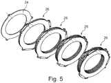
- the illustrated intermediate plate assembly 10 has an intermediate plate 12 which can frictionally press a friction disk of a clutch disk via a first axial side 14 and a second axial side 16.
- the intermediate plate 12 has a first fastening shoulder 18 protruding radially outward and a second fastening shoulder 20 protruding radially outward.
- a spring element 22 designed as a leaf spring is preassembled with the first fastening attachment 20.
- three spring elements 22 distributed uniformly in the circumferential direction are provided in each case.
- the intermediate plate assembly 10 can with the in Fig. 2 pressure plate 24 shown are connected.
- the pressure plate 24 also has the radially outwardly projecting second fastening lugs 20, with which the associated spring element 22 can be connected.
- the pressure plate 24 can be configured identically to the intermediate plate 12 as an identical part, in which case the first fastening lugs 18 can be inoperative.
- the lamellar pack 26 shown here.
- the spring element 22 can be riveted to the first attachment attachment 18 of the intermediate plate 12 and to the second attachment attachment 20 of the pressure plate 24.
- the distance between the first attachment attachment 18 and the second attachment attachment 20 of the intermediate plate 12 in the circumferential direction is selected such that the second attachment attachment 20 is not covered by the spring element 22, so that it can be easily installed.
- the second fastening shoulder 20 offset in the circumferential direction enables a further intermediate plate 30 of a further intermediate plate 30 with the free second fastening shoulder 20 of the intermediate plate 12 via a further spring element 28 configured as a leaf spring to connect further intermediate plate assembly 10, as in Fig. 4 shown.
- the further spring element 28 can easily be riveted to the second fastening attachment 20, neither the fastening element 22 of the previous intermediate plate assembly 10 nor the further intermediate plate 30 of the subsequent intermediate plate assembly 10 impairing the mountability.
- the disk pack 26 can be successively attached to a further intermediate plate assembly 10 in further assembly steps until a desired number of intermediate plates 12, 30 with a corresponding number of friction contact points to the friction disks of the clutch disk is reached.
- the plate pack 26 is formed starting with the pressure plate 24 by successively attaching the intermediate plate modules 10.
- the intermediate plate structural units 10 can be preassembled in such a way that the further spring element 28 is preassembled with the second attachment attachment 20 and not the spring element 22 with the first attachment attachment 18.
Landscapes
- Engineering & Computer Science (AREA)
- General Engineering & Computer Science (AREA)
- Mechanical Engineering (AREA)
- Mechanical Operated Clutches (AREA)
Claims (9)
- Paquet de lamelles pour un embrayage à disques multiples comprenant
un plateau de pression (24), pouvant être déplacé axialement par un élément d'actionnement, pour presser un disque d'embrayage ayant une pluralité de disques de friction entre le plateau de pression (24) et un contre-plateau,
un plateau intermédiaire (12), en particulier réalisé sous forme de lamelle en forme de disque, pour presser un disque de friction du disque d'embrayage sur un premier côté axial (14) faisant face au plateau de pression (24) et pour presser un disque de friction du disque d'embrayage sur un second côté axial (14) opposé au plateau de pression (24) et
un élément ressort (22) relié au plateau de pression (24) et au plateau intermédiaire (12) pour le positionnement automatique du plateau intermédiaire (12) à une distance axiale définie par rapport au plateau de pression (24), caractérisé en ce qu'en au moins un autre plateau intermédiaire (30) est prévu pour presser un disque de friction du disque d'embrayage sur un premier côté axial (14) faisant face au plateau de pression (24) et pour presser un disque de friction du disque d'embrayage sur un second côté axial (16) opposé au plateau de pression (24), dans lequel l'autre plateau intermédiaire (30) est relié par un autre élément ressort (28) au plateau intermédiaire (12, 30) suivant en direction du plateau de pression (24) et l'autre élément ressort (28) est prévu pour le positionnement automatique de l'autre plateau intermédiaire (30) à une distance axiale définie par rapport au plateau intermédiaire (12, 30) suivant en direction du plateau de pression (24). - Paquet de lamelles selon la revendication 1, caractérisé en ce que l'autre plateau intermédiaire (30) présente une première attache de fixation (18) pour la fixation, en particulier le rivetage, de l'élément ressort (22, 28) faisant face au plateau de pression (24) et une seconde attache de fixation (20) décalée dans la direction circonférentielle par rapport à la première attache de fixation (18) pour la fixation, en particulier le rivetage, de l'élément ressort (22, 28) opposé au plateau de pression (24), la seconde attache de fixation (20), vue dans la direction axiale, étant positionnée décalée par rapport à l'élément ressort (22, 28) suivant en direction du plateau de pression (24).
- Paquet de lamelles selon la revendication 2, caractérisé en ce que, pour une distance d des centres de gravité de la première attache de fixation (18) et de la seconde attache de fixation (20) dans la direction circonférentielle et un prolongement I de l'élément ressort (22) et/ou de l'autre élément ressort (28) dans la direction circonférentielle, 1,00 ≤ d/l, en particulier 1,00 ≤ d/l ≤ 1,50, de préférence 1,01 ≤ d/l ≤ 1,30, plus préférablement 1,05 ≤ d/1 < 1,20 et de manière particulièrement préférée 1,10 ≤ d/1 < 1,15 s'applique.
- Paquet de lamelles selon la revendication 2 ou 3, caractérisé en ce que la première attache de fixation (18) de l'autre plateau intermédiaire (30), vue dans la direction axiale, est positionnée décalée par rapport à une première attache de fixation (18) d'un plateau intermédiaire (12, 30) suivant en direction du plateau de pression (224).
- Paquet de lamelles selon l'une quelconque des revendications 1 à 4, caractérisé en ce que l'autre élément ressort (28), vu dans la direction axiale, recouvre partiellement un élément ressort (22, 28) suivant en direction du plateau de pression (24).
- Paquet de lamelles selon l'une quelconque des revendications 1 à 5, caractérisé en ce que l'élément ressort (22) et/ou l'autre élément ressort (28) est réalisé sous forme de ressort à lame s'étendant essentiellement dans la direction tangentielle et/ou dans la direction circonférentielle.
- Embrayage à disques multiples, en particulier embrayage à lamelles humide, pour accoupler au moins un arbre d'entrée de transmission d'une transmission de véhicule automobile avec un arbre d'entraînement d'un moteur de véhicule automobile, comprenant un contre-plateau pour initier ou dévier un couple du moteur de véhicule automobile, un disque d'embrayage pour dévier ou initier le couple et un paquet de lamelles (26) selon l'une quelconque des revendications 1 à 6 pour presser par friction le disque d'embrayage avec le contre-plateau, le plateau intermédiaire (12) et/ou le au moins un autre plateau intermédiaire (30) du paquet de lamelles (26) pouvant tourner par rapport au contre-plateau dans la direction circonférentielle.
- Procédé de montage d'un paquet de lamelles (26) selon l'une quelconque des revendications 1 à 7, en particulier pour un embrayage à disques multiples selon la revendication 8, dans lequel l'élément ressort (22) faisant face au plateau de pression (24) est relié au plateau intermédiaire (12) et/ou l'autre élément ressort (28) faisant face au plateau de pression (24) est relié à l'autre plateau intermédiaire (30) pour former un ensemble de plateaux intermédiaires (10),
l'ensemble de plateaux intermédiaires (10) est relié au plateau de pression (24) et
par la suite, un autre ensemble de plateaux intermédiaires (10) est relié au côté, opposé au plateau de pression (24), du plateau intermédiaire (12, 30) de l'ensemble de plateaux intermédiaires (10) précédemment relié jusqu'à ce qu'un nombre prédéfini de plateaux intermédiaires (12, 30) du paquet de lamelles (26) soit atteint. - Procédé de montage d'un paquet de lamelles (26) selon l'une quelconque des revendications 1 à 7, en particulier pour un embrayage à disques multiples selon la revendication 7, dans lequel l'autre élément ressort (28) opposé au plateau de pression (24) est relié au plateau intermédiaire (12) et/ou l'autre élément ressort (28) opposé au plateau de pression (24) est relié à l'autre plateau intermédiaire (30) pour former un ensemble de plateaux intermédiaires (10),
l'ensemble de plateaux intermédiaires (10) est relié à un contre-plateau ou à un ensemble de plateaux intermédiaires (10),
par la suite, un autre ensemble de plateaux intermédiaires (10) est relié au côté, faisant face au plateau de pression (24), du plateau intermédiaire (30) de l'ensemble de plateaux intermédiaires (10) précédemment relié jusqu'à ce qu'un nombre prédéfini de plateaux intermédiaires (12, 30) du paquet de lamelles (26) soit atteint et
par la suite, le plateau de pression (24) est relié par l'élément ressort (22) au plateau intermédiaire (12) de l'ensemble de plateaux intermédiaires (10) précédemment relié.
Applications Claiming Priority (2)
| Application Number | Priority Date | Filing Date | Title |
|---|---|---|---|
| DE102015213951.4A DE102015213951A1 (de) | 2015-07-23 | 2015-07-23 | Lamellenpaket für eine Mehrscheibenkupplung und Verfahren zur Montage eines Lamellenpakets |
| PCT/DE2016/200305 WO2017012618A1 (fr) | 2015-07-23 | 2016-07-04 | Paquet de lamelles pour embrayage à disques multiples et procédé de montage d'un paquet de lamelles |
Publications (2)
| Publication Number | Publication Date |
|---|---|
| EP3341625A1 EP3341625A1 (fr) | 2018-07-04 |
| EP3341625B1 true EP3341625B1 (fr) | 2021-06-16 |
Family
ID=56549996
Family Applications (1)
| Application Number | Title | Priority Date | Filing Date |
|---|---|---|---|
| EP16742159.3A Active EP3341625B1 (fr) | 2015-07-23 | 2016-07-04 | Paquet de lamelles pour embrayage à disques multiples et procédé de montage d'un paquet de lamelles |
Country Status (4)
| Country | Link |
|---|---|
| EP (1) | EP3341625B1 (fr) |
| CN (1) | CN107735590B (fr) |
| DE (2) | DE102015213951A1 (fr) |
| WO (1) | WO2017012618A1 (fr) |
Families Citing this family (3)
| Publication number | Priority date | Publication date | Assignee | Title |
|---|---|---|---|---|
| DE102017108655B3 (de) * | 2017-04-24 | 2018-04-12 | Schaeffler Technologies AG & Co. KG | Hybridmodul mit belüfteter Lamellenkupplung |
| JP7176392B2 (ja) * | 2018-12-11 | 2022-11-22 | 株式会社ジェイテクト | クラッチ装置 |
| DE102019127238A1 (de) | 2019-04-10 | 2020-10-15 | Schaeffler Technologies AG & Co. KG | Lamellenkupplung, insbesondere für einen Hybrid-Antriebsstrang |
Citations (6)
| Publication number | Priority date | Publication date | Assignee | Title |
|---|---|---|---|---|
| DE702033C (de) * | 1939-06-25 | 1941-01-30 | Fichtel & Sachs Akt Ges | Reibscheibenkupplung |
| US2385517A (en) * | 1944-01-19 | 1945-09-25 | Gen Motors Corp | Clutch |
| US6070708A (en) * | 1996-09-25 | 2000-06-06 | Exedy Corporation | Twin-clutch |
| US20100133056A1 (en) * | 2008-12-01 | 2010-06-03 | Mccutcheon Steven E | Positive Clutch Plate Separator System |
| DE102012213143A1 (de) * | 2012-07-26 | 2014-01-30 | Schaeffler Technologies AG & Co. KG | Mehrscheibenkupplung |
| DE102013112591A1 (de) * | 2012-11-16 | 2014-05-22 | Exedy Corporation | Kupplungsvorrichtung |
Family Cites Families (10)
| Publication number | Priority date | Publication date | Assignee | Title |
|---|---|---|---|---|
| AT261330B (de) * | 1966-06-01 | 1968-04-25 | Heid Ag Maschf | Kupplungslamelle bzw. Bremslamelle und mit diesen ausgestattete Lamellenkupplung oder -bremse |
| JP2009162372A (ja) * | 2008-01-10 | 2009-07-23 | Ogura Clutch Co Ltd | 多板式クラッチ |
| DE102009057353A1 (de) * | 2009-12-07 | 2011-06-09 | Borgwarner Inc., Auburn Hills | Lamellenkupplung mit einer Federeinrichtung |
| TWI445384B (zh) | 2010-04-26 | 2014-07-11 | Htc Corp | 通訊控制方法、通訊裝置及電腦程式產品 |
| US8640842B2 (en) * | 2011-03-09 | 2014-02-04 | American Axle & Manufacturing, Inc. | Clutch plate having integrated separating feature |
| DE102011018589A1 (de) | 2011-04-26 | 2012-10-31 | Schaeffler Technologies AG & Co. KG | Zweischeibenkupplung |
| CN202251521U (zh) * | 2011-05-31 | 2012-05-30 | 姜成立 | 新型摩擦离合器及其分离结合装置 |
| DE102013202686A1 (de) * | 2012-03-16 | 2013-09-19 | Schaeffler Technologies AG & Co. KG | Reibungskupplung mit Fliehkraftpendel |
| DE102014204001A1 (de) * | 2013-04-29 | 2014-10-30 | Schaeffler Technologies Gmbh & Co. Kg | Blattfeder für eine Reibungskupplung sowie Verwendung einer Blattfeder |
| DE112015001499A5 (de) * | 2014-03-27 | 2017-01-19 | Schaeffler Technologies AG & Co. KG | Zwischenplatte für eine Mehrscheibenkupplung sowie Verfahren zur Herstellung einer Zwischenplatte |
-
2015
- 2015-07-23 DE DE102015213951.4A patent/DE102015213951A1/de not_active Withdrawn
-
2016
- 2016-07-04 EP EP16742159.3A patent/EP3341625B1/fr active Active
- 2016-07-04 WO PCT/DE2016/200305 patent/WO2017012618A1/fr active Application Filing
- 2016-07-04 CN CN201680040058.6A patent/CN107735590B/zh active Active
- 2016-07-04 DE DE112016003317.6T patent/DE112016003317A5/de not_active Withdrawn
Patent Citations (6)
| Publication number | Priority date | Publication date | Assignee | Title |
|---|---|---|---|---|
| DE702033C (de) * | 1939-06-25 | 1941-01-30 | Fichtel & Sachs Akt Ges | Reibscheibenkupplung |
| US2385517A (en) * | 1944-01-19 | 1945-09-25 | Gen Motors Corp | Clutch |
| US6070708A (en) * | 1996-09-25 | 2000-06-06 | Exedy Corporation | Twin-clutch |
| US20100133056A1 (en) * | 2008-12-01 | 2010-06-03 | Mccutcheon Steven E | Positive Clutch Plate Separator System |
| DE102012213143A1 (de) * | 2012-07-26 | 2014-01-30 | Schaeffler Technologies AG & Co. KG | Mehrscheibenkupplung |
| DE102013112591A1 (de) * | 2012-11-16 | 2014-05-22 | Exedy Corporation | Kupplungsvorrichtung |
Also Published As
| Publication number | Publication date |
|---|---|
| EP3341625A1 (fr) | 2018-07-04 |
| WO2017012618A1 (fr) | 2017-01-26 |
| DE112016003317A5 (de) | 2018-04-26 |
| CN107735590B (zh) | 2020-01-10 |
| CN107735590A (zh) | 2018-02-23 |
| DE102015213951A1 (de) | 2017-01-26 |
Similar Documents
| Publication | Publication Date | Title |
|---|---|---|
| EP3069035B1 (fr) | Embrayage à friction | |
| DE112008001561B4 (de) | Kupplungsanordnung, insbesondere nasslaufende Doppelkupplungsanordnung | |
| EP3069033B1 (fr) | Embrayage à friction | |
| EP3123044A1 (fr) | Plaque de pression et boîte de sécurité sous forme de composant commun | |
| EP3953596B1 (fr) | Embrayage multidisques, en particulier pour un groupe motopropulseur hybride | |
| EP3111102B1 (fr) | Dispositif d'embrayage | |
| EP3341625B1 (fr) | Paquet de lamelles pour embrayage à disques multiples et procédé de montage d'un paquet de lamelles | |
| WO2015120845A1 (fr) | Dispositif d'embrayage normalement embrayé | |
| DE102014203416A1 (de) | Reibungskupplung | |
| EP3526886B1 (fr) | Dispositif de couplage | |
| WO2019120366A1 (fr) | Unité de transmission de couple et chaîne cinématique | |
| DE102013206548A1 (de) | Druckplattenbaugruppe und Kupplungsvorrichtung mit Druckplattenbaugruppe | |
| DE102007027121A1 (de) | Doppelkupplung | |
| DE102016215490B3 (de) | Doppelkupplung | |
| EP1521005B1 (fr) | Unité d'embrayage et/ou de frein | |
| DE102017130853B4 (de) | Kupplungseinrichtung | |
| WO2013110257A1 (fr) | Dispositif d'embrayage | |
| EP3350465A1 (fr) | Plateau de pression pour un embrayage à friction et embrayage à friction | |
| DE102009004718A1 (de) | Kupplungsaggregat | |
| EP3874174B1 (fr) | Embrayage à friction | |
| DE102019118347B3 (de) | Drucktopf zum Betätigen einer Reibungskupplung | |
| DE102017112332A1 (de) | Mehrscheibenkupplung | |
| DE102018117326A1 (de) | Lamellenkupplung mit Rückstellelement zum Lüften | |
| DE102014200527A1 (de) | Reibungskupplung | |
| EP3833885B1 (fr) | Paquet de lamelles avec une souplesse axiale spécialement appliquée |
Legal Events
| Date | Code | Title | Description |
|---|---|---|---|
| STAA | Information on the status of an ep patent application or granted ep patent |
Free format text: STATUS: THE INTERNATIONAL PUBLICATION HAS BEEN MADE |
|
| PUAI | Public reference made under article 153(3) epc to a published international application that has entered the european phase |
Free format text: ORIGINAL CODE: 0009012 |
|
| STAA | Information on the status of an ep patent application or granted ep patent |
Free format text: STATUS: REQUEST FOR EXAMINATION WAS MADE |
|
| 17P | Request for examination filed |
Effective date: 20180427 |
|
| AK | Designated contracting states |
Kind code of ref document: A1 Designated state(s): AL AT BE BG CH CY CZ DE DK EE ES FI FR GB GR HR HU IE IS IT LI LT LU LV MC MK MT NL NO PL PT RO RS SE SI SK SM TR |
|
| AX | Request for extension of the european patent |
Extension state: BA ME |
|
| DAV | Request for validation of the european patent (deleted) | ||
| DAX | Request for extension of the european patent (deleted) | ||
| STAA | Information on the status of an ep patent application or granted ep patent |
Free format text: STATUS: EXAMINATION IS IN PROGRESS |
|
| 17Q | First examination report despatched |
Effective date: 20190412 |
|
| STAA | Information on the status of an ep patent application or granted ep patent |
Free format text: STATUS: EXAMINATION IS IN PROGRESS |
|
| GRAP | Despatch of communication of intention to grant a patent |
Free format text: ORIGINAL CODE: EPIDOSNIGR1 |
|
| STAA | Information on the status of an ep patent application or granted ep patent |
Free format text: STATUS: GRANT OF PATENT IS INTENDED |
|
| INTG | Intention to grant announced |
Effective date: 20210317 |
|
| GRAS | Grant fee paid |
Free format text: ORIGINAL CODE: EPIDOSNIGR3 |
|
| GRAA | (expected) grant |
Free format text: ORIGINAL CODE: 0009210 |
|
| STAA | Information on the status of an ep patent application or granted ep patent |
Free format text: STATUS: THE PATENT HAS BEEN GRANTED |
|
| AK | Designated contracting states |
Kind code of ref document: B1 Designated state(s): AL AT BE BG CH CY CZ DE DK EE ES FI FR GB GR HR HU IE IS IT LI LT LU LV MC MK MT NL NO PL PT RO RS SE SI SK SM TR |
|
| REG | Reference to a national code |
Ref country code: GB Ref legal event code: FG4D Free format text: NOT ENGLISH |
|
| REG | Reference to a national code |
Ref country code: CH Ref legal event code: EP |
|
| REG | Reference to a national code |
Ref country code: DE Ref legal event code: R096 Ref document number: 502016013238 Country of ref document: DE |
|
| REG | Reference to a national code |
Ref country code: AT Ref legal event code: REF Ref document number: 1402588 Country of ref document: AT Kind code of ref document: T Effective date: 20210715 |
|
| REG | Reference to a national code |
Ref country code: IE Ref legal event code: FG4D Free format text: LANGUAGE OF EP DOCUMENT: GERMAN |
|
| REG | Reference to a national code |
Ref country code: LT Ref legal event code: MG9D |
|
| PG25 | Lapsed in a contracting state [announced via postgrant information from national office to epo] |
Ref country code: HR Free format text: LAPSE BECAUSE OF FAILURE TO SUBMIT A TRANSLATION OF THE DESCRIPTION OR TO PAY THE FEE WITHIN THE PRESCRIBED TIME-LIMIT Effective date: 20210616 Ref country code: BG Free format text: LAPSE BECAUSE OF FAILURE TO SUBMIT A TRANSLATION OF THE DESCRIPTION OR TO PAY THE FEE WITHIN THE PRESCRIBED TIME-LIMIT Effective date: 20210916 Ref country code: LT Free format text: LAPSE BECAUSE OF FAILURE TO SUBMIT A TRANSLATION OF THE DESCRIPTION OR TO PAY THE FEE WITHIN THE PRESCRIBED TIME-LIMIT Effective date: 20210616 Ref country code: FI Free format text: LAPSE BECAUSE OF FAILURE TO SUBMIT A TRANSLATION OF THE DESCRIPTION OR TO PAY THE FEE WITHIN THE PRESCRIBED TIME-LIMIT Effective date: 20210616 |
|
| REG | Reference to a national code |
Ref country code: NL Ref legal event code: MP Effective date: 20210616 |
|
| PG25 | Lapsed in a contracting state [announced via postgrant information from national office to epo] |
Ref country code: RS Free format text: LAPSE BECAUSE OF FAILURE TO SUBMIT A TRANSLATION OF THE DESCRIPTION OR TO PAY THE FEE WITHIN THE PRESCRIBED TIME-LIMIT Effective date: 20210616 Ref country code: SE Free format text: LAPSE BECAUSE OF FAILURE TO SUBMIT A TRANSLATION OF THE DESCRIPTION OR TO PAY THE FEE WITHIN THE PRESCRIBED TIME-LIMIT Effective date: 20210616 Ref country code: NO Free format text: LAPSE BECAUSE OF FAILURE TO SUBMIT A TRANSLATION OF THE DESCRIPTION OR TO PAY THE FEE WITHIN THE PRESCRIBED TIME-LIMIT Effective date: 20210916 Ref country code: GR Free format text: LAPSE BECAUSE OF FAILURE TO SUBMIT A TRANSLATION OF THE DESCRIPTION OR TO PAY THE FEE WITHIN THE PRESCRIBED TIME-LIMIT Effective date: 20210917 Ref country code: LV Free format text: LAPSE BECAUSE OF FAILURE TO SUBMIT A TRANSLATION OF THE DESCRIPTION OR TO PAY THE FEE WITHIN THE PRESCRIBED TIME-LIMIT Effective date: 20210616 |
|
| PG25 | Lapsed in a contracting state [announced via postgrant information from national office to epo] |
Ref country code: CZ Free format text: LAPSE BECAUSE OF FAILURE TO SUBMIT A TRANSLATION OF THE DESCRIPTION OR TO PAY THE FEE WITHIN THE PRESCRIBED TIME-LIMIT Effective date: 20210616 Ref country code: EE Free format text: LAPSE BECAUSE OF FAILURE TO SUBMIT A TRANSLATION OF THE DESCRIPTION OR TO PAY THE FEE WITHIN THE PRESCRIBED TIME-LIMIT Effective date: 20210616 Ref country code: SM Free format text: LAPSE BECAUSE OF FAILURE TO SUBMIT A TRANSLATION OF THE DESCRIPTION OR TO PAY THE FEE WITHIN THE PRESCRIBED TIME-LIMIT Effective date: 20210616 Ref country code: SK Free format text: LAPSE BECAUSE OF FAILURE TO SUBMIT A TRANSLATION OF THE DESCRIPTION OR TO PAY THE FEE WITHIN THE PRESCRIBED TIME-LIMIT Effective date: 20210616 Ref country code: NL Free format text: LAPSE BECAUSE OF FAILURE TO SUBMIT A TRANSLATION OF THE DESCRIPTION OR TO PAY THE FEE WITHIN THE PRESCRIBED TIME-LIMIT Effective date: 20210616 Ref country code: PT Free format text: LAPSE BECAUSE OF FAILURE TO SUBMIT A TRANSLATION OF THE DESCRIPTION OR TO PAY THE FEE WITHIN THE PRESCRIBED TIME-LIMIT Effective date: 20211018 Ref country code: RO Free format text: LAPSE BECAUSE OF FAILURE TO SUBMIT A TRANSLATION OF THE DESCRIPTION OR TO PAY THE FEE WITHIN THE PRESCRIBED TIME-LIMIT Effective date: 20210616 Ref country code: ES Free format text: LAPSE BECAUSE OF FAILURE TO SUBMIT A TRANSLATION OF THE DESCRIPTION OR TO PAY THE FEE WITHIN THE PRESCRIBED TIME-LIMIT Effective date: 20210616 |
|
| PG25 | Lapsed in a contracting state [announced via postgrant information from national office to epo] |
Ref country code: PL Free format text: LAPSE BECAUSE OF FAILURE TO SUBMIT A TRANSLATION OF THE DESCRIPTION OR TO PAY THE FEE WITHIN THE PRESCRIBED TIME-LIMIT Effective date: 20210616 |
|
| REG | Reference to a national code |
Ref country code: CH Ref legal event code: PL |
|
| REG | Reference to a national code |
Ref country code: DE Ref legal event code: R097 Ref document number: 502016013238 Country of ref document: DE |
|
| PG25 | Lapsed in a contracting state [announced via postgrant information from national office to epo] |
Ref country code: MC Free format text: LAPSE BECAUSE OF FAILURE TO SUBMIT A TRANSLATION OF THE DESCRIPTION OR TO PAY THE FEE WITHIN THE PRESCRIBED TIME-LIMIT Effective date: 20210616 |
|
| REG | Reference to a national code |
Ref country code: BE Ref legal event code: MM Effective date: 20210731 |
|
| PLBE | No opposition filed within time limit |
Free format text: ORIGINAL CODE: 0009261 |
|
| STAA | Information on the status of an ep patent application or granted ep patent |
Free format text: STATUS: NO OPPOSITION FILED WITHIN TIME LIMIT |
|
| PG25 | Lapsed in a contracting state [announced via postgrant information from national office to epo] |
Ref country code: LI Free format text: LAPSE BECAUSE OF NON-PAYMENT OF DUE FEES Effective date: 20210731 Ref country code: DK Free format text: LAPSE BECAUSE OF FAILURE TO SUBMIT A TRANSLATION OF THE DESCRIPTION OR TO PAY THE FEE WITHIN THE PRESCRIBED TIME-LIMIT Effective date: 20210616 Ref country code: CH Free format text: LAPSE BECAUSE OF NON-PAYMENT OF DUE FEES Effective date: 20210731 |
|
| 26N | No opposition filed |
Effective date: 20220317 |
|
| GBPC | Gb: european patent ceased through non-payment of renewal fee |
Effective date: 20210916 |
|
| PG25 | Lapsed in a contracting state [announced via postgrant information from national office to epo] |
Ref country code: LU Free format text: LAPSE BECAUSE OF NON-PAYMENT OF DUE FEES Effective date: 20210704 Ref country code: AL Free format text: LAPSE BECAUSE OF FAILURE TO SUBMIT A TRANSLATION OF THE DESCRIPTION OR TO PAY THE FEE WITHIN THE PRESCRIBED TIME-LIMIT Effective date: 20210616 |
|
| PG25 | Lapsed in a contracting state [announced via postgrant information from national office to epo] |
Ref country code: IT Free format text: LAPSE BECAUSE OF FAILURE TO SUBMIT A TRANSLATION OF THE DESCRIPTION OR TO PAY THE FEE WITHIN THE PRESCRIBED TIME-LIMIT Effective date: 20210616 Ref country code: IE Free format text: LAPSE BECAUSE OF NON-PAYMENT OF DUE FEES Effective date: 20210704 Ref country code: GB Free format text: LAPSE BECAUSE OF NON-PAYMENT OF DUE FEES Effective date: 20210916 Ref country code: FR Free format text: LAPSE BECAUSE OF NON-PAYMENT OF DUE FEES Effective date: 20210816 Ref country code: BE Free format text: LAPSE BECAUSE OF NON-PAYMENT OF DUE FEES Effective date: 20210731 |
|
| REG | Reference to a national code |
Ref country code: AT Ref legal event code: MM01 Ref document number: 1402588 Country of ref document: AT Kind code of ref document: T Effective date: 20210704 |
|
| PG25 | Lapsed in a contracting state [announced via postgrant information from national office to epo] |
Ref country code: AT Free format text: LAPSE BECAUSE OF NON-PAYMENT OF DUE FEES Effective date: 20210704 |
|
| PG25 | Lapsed in a contracting state [announced via postgrant information from national office to epo] |
Ref country code: HU Free format text: LAPSE BECAUSE OF FAILURE TO SUBMIT A TRANSLATION OF THE DESCRIPTION OR TO PAY THE FEE WITHIN THE PRESCRIBED TIME-LIMIT; INVALID AB INITIO Effective date: 20160704 |
|
| P01 | Opt-out of the competence of the unified patent court (upc) registered |
Effective date: 20230522 |
|
| PG25 | Lapsed in a contracting state [announced via postgrant information from national office to epo] |
Ref country code: CY Free format text: LAPSE BECAUSE OF FAILURE TO SUBMIT A TRANSLATION OF THE DESCRIPTION OR TO PAY THE FEE WITHIN THE PRESCRIBED TIME-LIMIT Effective date: 20210616 |
|
| PGFP | Annual fee paid to national office [announced via postgrant information from national office to epo] |
Ref country code: DE Payment date: 20230920 Year of fee payment: 8 |
|
| PG25 | Lapsed in a contracting state [announced via postgrant information from national office to epo] |
Ref country code: MK Free format text: LAPSE BECAUSE OF FAILURE TO SUBMIT A TRANSLATION OF THE DESCRIPTION OR TO PAY THE FEE WITHIN THE PRESCRIBED TIME-LIMIT Effective date: 20210616 |