EP3340920B1 - Schutzvorrichtung zur verwendung bei mundchirurgischen eingriffen - Google Patents
Schutzvorrichtung zur verwendung bei mundchirurgischen eingriffen Download PDFInfo
- Publication number
- EP3340920B1 EP3340920B1 EP16806422.8A EP16806422A EP3340920B1 EP 3340920 B1 EP3340920 B1 EP 3340920B1 EP 16806422 A EP16806422 A EP 16806422A EP 3340920 B1 EP3340920 B1 EP 3340920B1
- Authority
- EP
- European Patent Office
- Prior art keywords
- mouth
- patient
- protection device
- tube
- tubes
- Prior art date
- Legal status (The legal status is an assumption and is not a legal conclusion. Google has not performed a legal analysis and makes no representation as to the accuracy of the status listed.)
- Active
Links
Images


Classifications
-
- A—HUMAN NECESSITIES
- A61—MEDICAL OR VETERINARY SCIENCE; HYGIENE
- A61C—DENTISTRY; APPARATUS OR METHODS FOR ORAL OR DENTAL HYGIENE
- A61C5/00—Filling or capping teeth
- A61C5/90—Oral protectors for use during treatment, e.g. lip or mouth protectors
-
- A—HUMAN NECESSITIES
- A61—MEDICAL OR VETERINARY SCIENCE; HYGIENE
- A61B—DIAGNOSIS; SURGERY; IDENTIFICATION
- A61B18/00—Surgical instruments, devices or methods for transferring non-mechanical forms of energy to or from the body
-
- A—HUMAN NECESSITIES
- A61—MEDICAL OR VETERINARY SCIENCE; HYGIENE
- A61B—DIAGNOSIS; SURGERY; IDENTIFICATION
- A61B90/00—Instruments, implements or accessories specially adapted for surgery or diagnosis and not covered by any of the groups A61B1/00 - A61B50/00, e.g. for luxation treatment or for protecting wound edges
- A61B90/04—Protection of tissue around surgical sites against effects of non-mechanical surgery, e.g. laser surgery
-
- A—HUMAN NECESSITIES
- A61—MEDICAL OR VETERINARY SCIENCE; HYGIENE
- A61C—DENTISTRY; APPARATUS OR METHODS FOR ORAL OR DENTAL HYGIENE
- A61C17/00—Devices for cleaning, polishing, rinsing or drying teeth, teeth cavities or prostheses; Saliva removers; Dental appliances for receiving spittle
- A61C17/06—Saliva removers; Accessories therefor
- A61C17/08—Aspiration nozzles
-
- A—HUMAN NECESSITIES
- A61—MEDICAL OR VETERINARY SCIENCE; HYGIENE
- A61C—DENTISTRY; APPARATUS OR METHODS FOR ORAL OR DENTAL HYGIENE
- A61C17/00—Devices for cleaning, polishing, rinsing or drying teeth, teeth cavities or prostheses; Saliva removers; Dental appliances for receiving spittle
- A61C17/06—Saliva removers; Accessories therefor
- A61C17/10—Saliva removers; Accessories therefor with mouth props, tongue guards, tongue depressors or cheek spreaders
-
- A—HUMAN NECESSITIES
- A61—MEDICAL OR VETERINARY SCIENCE; HYGIENE
- A61B—DIAGNOSIS; SURGERY; IDENTIFICATION
- A61B17/00—Surgical instruments, devices or methods
- A61B17/02—Surgical instruments, devices or methods for holding wounds open, e.g. retractors; Tractors
-
- A—HUMAN NECESSITIES
- A61—MEDICAL OR VETERINARY SCIENCE; HYGIENE
- A61B—DIAGNOSIS; SURGERY; IDENTIFICATION
- A61B18/00—Surgical instruments, devices or methods for transferring non-mechanical forms of energy to or from the body
- A61B2018/00315—Surgical instruments, devices or methods for transferring non-mechanical forms of energy to or from the body for treatment of particular body parts
- A61B2018/00321—Head or parts thereof
-
- A—HUMAN NECESSITIES
- A61—MEDICAL OR VETERINARY SCIENCE; HYGIENE
- A61B—DIAGNOSIS; SURGERY; IDENTIFICATION
- A61B2218/00—Details of surgical instruments, devices or methods for transferring non-mechanical forms of energy to or from the body
- A61B2218/001—Details of surgical instruments, devices or methods for transferring non-mechanical forms of energy to or from the body having means for irrigation and/or aspiration of substances to and/or from the surgical site
- A61B2218/007—Aspiration
- A61B2218/008—Aspiration for smoke evacuation
Definitions
- the present invention relates to surgical aids, tools and appliances and more particularly, relates to a device for use as a surgical aid to increase the safety of both patient and medical staff during surgery. More particularly the invention relates to a device which protects oral tissues from burns and other potential damage which may be occasioned during oral surgery. More particularly the present invention provides a disposable guard which protects the soft tissues of a patient during surgery of the oral cavity.
- the invention according to one embodiment further provides in the device a passage for evacuation of noxious or toxic fumes and gases which are generated when soft tissue is divided by a diathermy knife.
- the invention further relates to a surgical kit including a range of disposable devices of various sizes to accommodate different patients and which each protect oral tissues from the burns and other potential damage.
- Oral surgery involves many procedures which include those performed on upper airways, tonsillectomy, adenoidectomy, palate surgery, tongue surgery, other transoral surgery, and certain dental procedures.
- Hot instruments such as diathermy (mono-polar electro-cautery), coblation (bipolar electro-cautery) and LASER to dissect or remove tissue to minimize blood loss compared to old fashion scalpel techniques.
- diathermy mono-polar electro-cautery
- coblation bipolar electro-cautery
- LASER LASER to dissect or remove tissue to minimize blood loss compared to old fashion scalpel techniques.
- the use of "hot instruments is now the standard and universal method. These instruments have a handle held by the surgeon, a shaft through which the current flows and a tip through which the electricity is applied to the tissue.
- the shaft has a thin layer of insulation.
- Ignition of built up anaesthetic gases/ oxygen in the mouth can also cause a flash fire.
- the shaft of a diathermy can become hot enough from transmitted heat during prolonged use in a procedure enough to burn soft tissues. There have been many reported cases of faulty insulation allowing electricity to emit from the shaft. During oral surgery using a diathermy, burning tissue causes an emission of a large plume of smoke which can potentially contain and carry viruses such as CJD, HPV, HIV etc as well as toxins which are the equivalent of smoking a packet of cigarettes per hour of exposure. Although the known dissection instrument has now changed to a "hot" dissector, the rest of the instruments and techniques have not changed or adapted from the time of "cold steel" dissection.
- a patient's mouth is held open for access to the surgical site.
- a patient's mouth is held open by a Boyle-Davis gag. This holds the mouth open wide along a Y axis but offers little protection for the facial and mouth tissues and particularly for the corners of the mouth.
- the instruments are passed into the mouth with the shaft of the instrument lying against the corners of the mouth as the mouth is a confined space.
- Some make-shift protection is offered by use of gauze squares folded up and draped about the corners of the mouth. Since this affords inadequate protection, the patient's tissue can be burnt away. Mouth burns during tonsillectomy is known in the medical literature.
- US 6267591 B1 discloses a dental prop, throat dam and retractor.
- US 5152686 A discloses a dental appliance.
- DE 202013101131 U1 discloses an instrument carrier for positioning a dental instrument.
- US 2859519 A discloses a dental retractor and saliva ejector.
- the present invention provides improvement in devices used in oral surgery and more particularly provide a disposable soft tissue protector which protects such structures as corners of the mouth during surgery. More particularly the invention provides a device which protects oral tissues from burns and other potential damage which may be occasioned during oral surgery. More particularly the present invention provides a disposable guard which protects the soft tissues of a patient during surgery of the oral cavity and is capable of receiving and evacuating gasses created by hot instruments.
- the present invention pertains to a protection device for use in oral surgery for providing a physical barrier between surgical instrumentation and a patient's soft tissue as claimed in claim 1.
- Advantageous aspects of the invention are defined in the dependent claims 2-9.
- the body of the device is manufactured from materials selected from plastics, metals or a combination of the two.
- the device may be manufactured from other materials which are preferably pliable or plastic, electrically insulating and thermally inert.
- the device is capable of self locating and remaining connected to the mouth of a patient, protecting such areas as the corner of the mouth and lips.
- the design geometry can be varied to suit different anatomical sizes enabling staff to select a size suitable for a particular patient. Typically a surgeon will place a return portion over the lip margins and crimp it against the mouth using its inbuilt plasticity.
- a kit of protection devices can be provided allowing a surgeon to select a suitable size for a particular patient anatomy.
- the body of the device is manufactured from materials selected from plastics, metals or a combination of the two.
- the device is preferably manufactured from materials which are pliable and plastic, electrically insulating and thermally inert.
- the device is capable of self locating and remaining connected to the mouth of a patient, protecting such areas as the corner of the mouth and lips.
- the shape of the device can be varied to suit different anatomical sizes enabling staff to select a size suitable for a particular patient.
- the device has inbuilt plasticity to enable a surgeon to crimp the device over at least a portion of lip margins.
- the device is manufactured from a rigid material or combination of materials which are non pliable and pre set to accommodate a particular patient's mouth.
- the device minimises risks of tissue burning and gas ingestion in oral surgeries by: 1. protecting the side of the mouth from thermal/electrical injury; and 2. providing continuous suction to clear the mouth of smoke plume and gases to ensure a clear view, minimize the emission of smoke to the surgeon and staff and to negate the need for an oral sucker and a nurse to hold it.
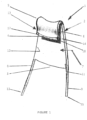
- Figure 1 shows a perspective view of a mouth protecting device 1 according to a preferred embodiment.
- Protector 1 comprises a body 2 having a first end 3 and second end 4. Second end 4 locates inside the mouth of a patient (not shown) and first end 3 locates outside the mouth of a patient with return portion 5 defining a recess 6 which accommodates and wraps around the lips of the patient.
- Return portion 5 according to one embodiment, resiliently deformable and/or pliable and allows a surgeon to adjust to accommodate the patient's lip.
- Body 2 includes a planar region 7 which, when device 1 is in use, lies against the outside of the patient's cheek and provides protection while the mouth is held open during surgery, a physical barrier between surgical instrumentation such as a hot diathermy and the cheek and to some extent the buccal region.
- Protector 1 includes tubes 8 and 9 adapted to respective edge regions 10 and 11 of body 2. These may be integrally formed with body 2 or alternatively connected to body 2 depending upon particular design requirements and selected materials of construction. Tubes 8 and 9 are joined to a vacuum line which evacuates gases from the surgical field ( see figures 8 ). Tube 8 has a first end 12 which when device 1 is in use locates inside a mouth of a patient and a second end 13 which terminates outside the mouth . Likewise tube 9 has a first end 14 which, when device 1 is in use, locates inside a mouth of a patient and a second end 15 which terminates outside the mouth. According to one embodiment, tubes 8 and 9 each include respective through passages 17 and 18 which provide a suction paths to evacuate the toxic gases which accumulate at the site of the oral surgery. Ends 13 and 15 engage a gas discharge tube ( see figure 8 ).
- Figure 2 shows with corresponding numbering a rear perspective view of the protector 1 of Figure 1 .
- Figure 3 shows with corresponding numbering a side perspective view of the protector of figure 1 .
- Figure 4 shows a side elevation view of the protector of figure 1 .
- Figure 5 shows a front elevation view of the protector of figure 1 .
- Figure 6 shows a top elevation view of the protector of figure 1 .
- Figure 7 shows a plan view of an open mouth 30 of a patient with a first protection device 31 and opposing second device 32 respectively engaging lip regions 33 and 34.
- Protector 31 comprises a body 35 having a first end 36 and second end 37. Second end 37 locates inside the mouth 30 and receives lip region 33 in recess 38 defined by radiused return 39.
- protector 32 comprises a body 40 having a first end 41 and second end 42. Second end 42 locates inside the mouth 30 and receives lip region 34 in recess 43 defined by radiused return 44.
- Return portions 39 and 44 are pliable and allow a surgeon to adjust to accommodate the patient's lip regions 33 and 34 respectively. According to one embodiment, return portions 39 and 44 are pliable and resiliently deformable. Body 35 of device 31 and body 40 of lie against and protect cheeks 46 and 47 respectively and provide a physical barrier to unwanted instrument contact with the patient.
- Protection device 31 includes tubes 50 and 51 adapted to respective edge regions of body 35. Tubes 50 and 51 are joined to a vacuum line 52 which evacuates gases away from the surgical field to a collection unit or other known collector. Likewise, protection device 32 includes tubes 53 and 54 adapted to respective edge regions of body 40. Tubes 53 and 54 are joined to a vacuum line 55 which also evacuates gases away from the surgical field to a collection unit or other known collector.
- FIG 7 employs bilateral opposing like devices, it will be appreciated by persons skilled in the art that the following combinations can also be employed: one device with gas evacuation tubes, two devices but only one with gas evacuation tubes.
- Figure 8 shows with corresponding numbering, the protection devices 31 and 32 of figure 8 each connected to respective vacuum discharge lines 52 and 55 which both terminate in a single line 56 en route to the gas collection apparatus (not shown).
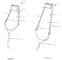
- Figure 9 shows a perspective enlarged view of a smaller version of a protective device 60 according to one embodiment connected to a vacuum tube 61.
- Protector 60 comprises a body 62 including a planar region 63 and tubes 64 and 65 preferably integrally formed with body 62. Tubes 64 and 65 are joined to vacuum line 61 which evacuates gases from the surgical field ( see figures 8 ).
- FIG 10 shows a more elongated version of a protective device 70 according to another embodiment.
- Protector 70 comprises an elongated body 72 including a planar region 74 having significantly increased surface area and elongated evacuation tubes 75 and 76. Tubes 75 and76 are joined to vacuum line 77 which evacuates gases from the surgical field.
- the vacuum tubes preferably enter the mouth to a depth as far as possible.
- the mid tube lengths of the vacuum tubes are preferably around 500mm long and are press fit into a Y shaped joiner.
- the width of the lip protector moulding and tube would be in the region of 25 - 30mm but other sizes are contemplated to accommodate different sized patient anatomies.
- the device is constructed flat with built in capacity for bending into shape by a user.
- the pliability may be introduced using an internal membrane in the body.
- the protection device comprises a moulded silicone body which is contoured to slide over a patient's lip and clamp lightly on walls of the cheek. The clamping force can be adjusted by the surgeon when locating the device on the patient's mouth.
- Incorporated in the moulded silicone are tubes which have a first end which locates in the mouth when the device is in situ and a second end extending outside the mouth. Each tube has a through passage which spans between the first and second ends.
- the tubes have an inside diameter within the range of 2mm-5mm and an outside diameter within the range of 3mm-7mm.
- a preferred tube size is 2mm inside diameter and 3.2mm outside diameter.
- the tubes are clear and either bonded to guide channels or moulded integral with the body of the device.
- the device is malleable and easily applied for self - retention in a corner-of-the-mouth.
- the devices Preferably, during surgery there is provided one on each side of the patient's mouth.
- one or both of the devices include integral suction tubes incorporated into the body of the device with the tubes being connected to known standard suction tubing.
- the protection device preferably has a length within the range 25 - 75mm but alternative sizes are contemplated.
- Materials of construction are selected from smooth, heat resistant, non reflective, semi-firm material, plastic/silastic or a coated thin malleable metal with a heat/electricity insulating coating. Selecting a malleable material allows the device to engage the lip region of the mouth and with sufficient clamping elasticity in the material to stay in place during surgery. This eliminates the need to use inefficient wet gauze squares which are currently in use and sit on the corners of the mouth.
- the device is single use and disposable although materials capable of sterilization are contemplated.
- the embodiments shown incorporate two lateral suction tubes, alternative embodiments are contemplated, such as but not limited to, use of one suction tube, location of a tube or tubes intermediate the edges or a tube which can be attached as required to the protection device.
- the suction is of a smoke plume, rather than fluid, the suction tubes/canulas do not need to be wide bore.
- the radii of curvature of the tubes and angles of repose are adapted to suit particular mouth geometry as required and to facilitate passage of gases.
- the suction tubing would preferably be around 30cm long with an end able to be attached to standard suction tubing.
- the suction tube includes a form of double adaptor so that theatre wall suction tubing can be used for both this device and a standard gas sucker.
- the devices are provided in a sterile, disposable kit including those with and without suction tubes and adaptors as required. The device described herein improves patient safety and is convenient for staff application.
Landscapes
- Health & Medical Sciences (AREA)
- Life Sciences & Earth Sciences (AREA)
- Animal Behavior & Ethology (AREA)
- Veterinary Medicine (AREA)
- Public Health (AREA)
- General Health & Medical Sciences (AREA)
- Oral & Maxillofacial Surgery (AREA)
- Epidemiology (AREA)
- Dentistry (AREA)
- Surgery (AREA)
- Biomedical Technology (AREA)
- Medical Informatics (AREA)
- Engineering & Computer Science (AREA)
- Heart & Thoracic Surgery (AREA)
- Molecular Biology (AREA)
- Nuclear Medicine, Radiotherapy & Molecular Imaging (AREA)
- Otolaryngology (AREA)
- Pathology (AREA)
- Surgical Instruments (AREA)
- Dental Tools And Instruments Or Auxiliary Dental Instruments (AREA)
- External Artificial Organs (AREA)
Claims (9)
- Schutzvorrichtung (1) zur Verwendung in der Oralchirurgie, um eine physische Barriere zwischen chirurgischen Instrumenten und dem Weichgewebe eines Patienten bereitzustellen,
die Vorrichtung aufweisend:einen Vorrichtungskörper (2) mit:- einem ersten Ende (3), das sich, während des Gebrauchs, außerhalb des Mundes eines Patienten befindet, und einem zweiten Ende (4), das sich, während des Gebrauchs, im Mund des Patienten befindet;- einen ebenen Bereich, der so angeordnet ist, dass er einer benachbarten Innenfläche des Mundes gegenüberliegt, und einen einstückig damit verbundenen Wangeneingriffsabschnitt, der aus demselben Material besteht, die jeweils gemeinsame Seitenkanten aufweisen;- einen im Wesentlichen U-förmigen Rücklaufabschnitt (5), durch den der Vorrichtungskörper (2) von dem ebenen Bereich innerhalb des Mundes zu dem Wangeneingriffsabschnitt außerhalb des Mundes übergeht, wobei der Rücklaufabschnitt (5) eine Aussparung (6) definiert, die so gestaltet ist, dass sie die Lippen des Patienten aufnimmt und umschließt;wobei der Rücklaufabschnitt (5) biegsam ist, was es der Vorrichtung (1) ermöglicht, sich einer anatomischen Form des Mundes des Patienten anzupassen und über mindestens einen Teil der Lippenränder des Patienten gequetscht zu werden, wobei der Vorrichtungskörper (2) Rohre (8, 9) enthält, die jeweils ein erstes Ende (12, 14), das so konfiguriert ist, dass es sich außerhalb des Mundes befindet, und ein zweites Ende (13, 15) haben, das so konfiguriert ist, dass es sich innerhalb des Mundes befindet, und die jeweils einen Durchgang haben, der sich von dem zweiten Ende (13, 15) zu dem ersten Ende (12, 14) erstreckt. - Schutzvorrichtung (1) nach Anspruch 1, wobei der Vorrichtungskörper (2) verformbar ist und manuell angepasst werden kann, um an verschiedenen Mundformen angepasst zu werden.
- Schutzvorrichtung (1) nach Anspruch 2, wobei die Vorrichtung (1) so konfiguriert ist, dass wenn sie in Gebrauch ist, ein kleiner Teil des Vorrichtungskörpers (2) innerhalb des Mundes und ein großer Teil des Vorrichtungskörpers (2) außerhalb des Mundes angeordnet ist.
- Schutzvorrichtung (1) nach Anspruch 3, wobei der im Wesentlichen U-förmige Rücklaufabschnitt (5) einstellbar ist, um sich der Mund- und Lippenform eines bestimmten Patienten anzupassen.
- Schutzvorrichtung (1) nach Anspruch 4, wobei sich ein Rohr (8) entlang einer Seite des Körpers der Vorrichtung und das andere Rohr (9) sich entlang einer gegenüberliegenden Seite des Körpers der Vorrichtung erstreckt.
- Schutzvorrichtung (1) nach Anspruch 5, wobei das erste Ende (12, 14) jedes dieser Rohre geeignet ist, um ein Auslassrohr (52, 55) aufzunehmen und zu halten, das sich außerhalb des Mundes befindet, um das Auslassen von gasförmigen Produkten aus dem Inneren des Mundes in einen Sammelbehälter oder in die Außenluft zu ermöglichen.
- Schutzvorrichtung (1) nach Anspruch 6, wobei das zweite Ende (13, 15) jedes Rohrs eine Öffnung aufweist, die zur Aufnahme von gasförmigem Abfluss geeignet ist, zur Ableitung über das erste Ende.
- Schutzvorrichtung (1) nach Anspruch 7, wobei der Körper (2) der Vorrichtung aus Materialien hergestellt ist, die aus Kunststoffen, Metallen oder einer Kombination der beiden ausgewählt sind.
- Schutzvorrichtung nach Anspruch 8, wobei die Vorrichtung (1) aus Materialien hergestellt ist, die biegsam sind, aus Kunststoff, elektrisch isolierend und thermisch inert.
Applications Claiming Priority (2)
| Application Number | Priority Date | Filing Date | Title |
|---|---|---|---|
| AU2015902167A AU2015902167A0 (en) | 2015-06-10 | A protective device for use in oral surgical procedures | |
| PCT/AU2016/000195 WO2016197179A1 (en) | 2015-06-10 | 2016-06-10 | A protective device for use in oral surgical procedures |
Publications (3)
| Publication Number | Publication Date |
|---|---|
| EP3340920A1 EP3340920A1 (de) | 2018-07-04 |
| EP3340920A4 EP3340920A4 (de) | 2019-08-28 |
| EP3340920B1 true EP3340920B1 (de) | 2024-09-11 |
Family
ID=57502728
Family Applications (1)
| Application Number | Title | Priority Date | Filing Date |
|---|---|---|---|
| EP16806422.8A Active EP3340920B1 (de) | 2015-06-10 | 2016-06-10 | Schutzvorrichtung zur verwendung bei mundchirurgischen eingriffen |
Country Status (8)
| Country | Link |
|---|---|
| US (1) | US11179225B2 (de) |
| EP (1) | EP3340920B1 (de) |
| JP (1) | JP7019564B2 (de) |
| CN (1) | CN108430380B (de) |
| AU (1) | AU2016275549B2 (de) |
| BR (1) | BR112017026307B1 (de) |
| MY (1) | MY192560A (de) |
| WO (1) | WO2016197179A1 (de) |
Families Citing this family (5)
| Publication number | Priority date | Publication date | Assignee | Title |
|---|---|---|---|---|
| CN108814533A (zh) * | 2018-04-20 | 2018-11-16 | 周国辉 | 一种医用口腔张开器 |
| US20210307876A1 (en) * | 2020-04-07 | 2021-10-07 | Chieh-Mao Lin | Hand tool with molar as resistance point |
| CN112294477B (zh) * | 2020-09-27 | 2021-10-22 | 宁波城市职业技术学院 | 一种带自吸功能的口腔治疗装置 |
| CN117915854A (zh) * | 2021-04-22 | 2024-04-19 | 罗公灿 | 控制能量传递特性的口腔插入用装置 |
| US20240293113A1 (en) * | 2023-03-03 | 2024-09-05 | Foot Innovations, Llc | Retractor device |
Family Cites Families (30)
| Publication number | Priority date | Publication date | Assignee | Title |
|---|---|---|---|---|
| US2859519A (en) * | 1957-03-15 | 1958-11-11 | Louis A Cohn | Dental retractor and saliva ejector |
| US3772790A (en) | 1971-08-09 | 1973-11-20 | Gett C Swan | Tooth isolating shield |
| US4053984A (en) * | 1976-08-05 | 1977-10-18 | Moss Dan E | Mouth prop |
| DE2710243A1 (de) * | 1977-03-09 | 1978-09-14 | Morton Dr Cohen | Zahnaerztliches geraet |
| JPS53117293A (en) * | 1977-03-18 | 1978-10-13 | Kouen Mooton | Dental apparatus for opening mouth and collecting saliva |
| DE3128953C2 (de) * | 1980-07-25 | 1986-07-03 | Peter 2000 Hamburg Scheer | Lippenexpander |
| EP0137090A1 (de) * | 1983-10-13 | 1985-04-17 | Giuseppe Totaro | Abschirmung für die Mundhöhle bei zahnärztlichen Arbeiten |
| US4562832A (en) * | 1984-01-21 | 1986-01-07 | Wilder Joseph R | Medical instrument and light pipe illumination assembly |
| US4889490A (en) * | 1988-02-11 | 1989-12-26 | Jenkinson Jeffrey A | Dental mask |
| US4947829A (en) * | 1988-05-10 | 1990-08-14 | Bullard James R | Modular blade laryngoscope |
| JPH03292951A (ja) * | 1990-04-10 | 1991-12-24 | Kyosuke Yamamoto | 誤飲防止・防湿装置 |
| US5152686A (en) | 1991-04-25 | 1992-10-06 | Calvin Duggan | Dental appliance |
| US5152300A (en) * | 1991-10-28 | 1992-10-06 | Horst Patricia J | Guard for protecting the corner of a patient's mouth |
| US5566684A (en) * | 1995-11-21 | 1996-10-22 | Dental Concepts Inc. | Custom fit mouthguard |
| US6213772B1 (en) * | 1999-04-14 | 2001-04-10 | Drident, L.L.C. | Oral isolation device with evacuation chambers |
| US6267591B1 (en) * | 2000-04-18 | 2001-07-31 | Ricky A. Barstow | Dental prop, throat dam and retractor |
| US20050074720A1 (en) * | 2002-11-22 | 2005-04-07 | Anderson Ross William | Apparatus for maintaining a dry field during dental procedures |
| US20080064001A1 (en) * | 2004-07-02 | 2008-03-13 | Discus Dental, Llc | Retracting Devices |
| US20080318183A1 (en) * | 2007-06-23 | 2008-12-25 | Colin Suzman | Bite block with snap-in positionable fluid ejector |
| BRPI0814609A2 (pt) * | 2007-07-19 | 2015-01-27 | Synthes Gmbh | Prendedor para fixar uma âncora óssea com relação a uma haste, e, sistema de preensão para montar em uma vértebra. |
| WO2009042957A2 (en) * | 2007-09-26 | 2009-04-02 | Indentiv, Llc | Methods, devices, systems, assemblies, and kits for tissue retraction in an oral cavity |
| CN101292910A (zh) * | 2008-06-13 | 2008-10-29 | 深圳市龙岗区人民医院 | 一种具有吸唾功能的开口器 |
| US20100119989A1 (en) * | 2008-11-12 | 2010-05-13 | Discus Dental, Llc | Retracting device |
| ES2378521T3 (es) | 2009-09-07 | 2012-04-13 | Hibrand Establishment | Protector dental |
| CA2805380C (en) * | 2010-07-15 | 2017-03-07 | Anton G.C. MILO | Suction device for evacuating fumes |
| US11576764B2 (en) * | 2012-12-07 | 2023-02-14 | Solmetex, Llc | Intraoral device with stability bar |
| DE202013101131U1 (de) | 2013-03-15 | 2014-06-16 | Elmar Metzger | Instrumententräger |
| WO2015051178A1 (en) * | 2013-10-02 | 2015-04-09 | Ndental, Llc | Patient controlled dental device and method |
| US9358086B2 (en) | 2014-05-22 | 2016-06-07 | Innerlite, Inc. | Intraoral device and method of use |
| PH12021552855A1 (en) * | 2019-05-10 | 2023-01-04 | Dryshield Llc | Dental mouthpiece |
-
2016
- 2016-06-10 EP EP16806422.8A patent/EP3340920B1/de active Active
- 2016-06-10 US US15/580,599 patent/US11179225B2/en active Active
- 2016-06-10 BR BR112017026307-6A patent/BR112017026307B1/pt active IP Right Grant
- 2016-06-10 AU AU2016275549A patent/AU2016275549B2/en active Active
- 2016-06-10 CN CN201680044570.8A patent/CN108430380B/zh active Active
- 2016-06-10 MY MYPI2017704717A patent/MY192560A/en unknown
- 2016-06-10 JP JP2018516605A patent/JP7019564B2/ja active Active
- 2016-06-10 WO PCT/AU2016/000195 patent/WO2016197179A1/en not_active Ceased
Also Published As
| Publication number | Publication date |
|---|---|
| US11179225B2 (en) | 2021-11-23 |
| EP3340920A4 (de) | 2019-08-28 |
| BR112017026307A2 (pt) | 2018-12-04 |
| JP2018516736A (ja) | 2018-06-28 |
| CN108430380B (zh) | 2022-06-07 |
| CN108430380A (zh) | 2018-08-21 |
| WO2016197179A1 (en) | 2016-12-15 |
| BR112017026307B1 (pt) | 2021-10-26 |
| AU2016275549B2 (en) | 2020-06-25 |
| JP7019564B2 (ja) | 2022-02-15 |
| EP3340920A1 (de) | 2018-07-04 |
| US20180168773A1 (en) | 2018-06-21 |
| AU2016275549A1 (en) | 2017-12-21 |
| MY192560A (en) | 2022-08-29 |
Similar Documents
| Publication | Publication Date | Title |
|---|---|---|
| AU2016275549B2 (en) | A protective device for use in oral surgical procedures | |
| JP7097914B2 (ja) | 歯科処置用の補助装置 | |
| EP2593155B1 (de) | Saugvorrichtung zum absaugen von dämpfen | |
| CN109328040B (zh) | 具有可扩展部分和负压源的手持式器械 | |
| US6926717B1 (en) | Electrosurgical breast electrode | |
| US20040049183A1 (en) | Electrosurgical tonsilar and adenoid electrode | |
| CN105407936B (zh) | 流体排空装置 | |
| US10675126B2 (en) | Combination lip retractor and guard with integrated light source, suction, and surgical smoke plume filter | |
| US9907621B2 (en) | Surgical pencil | |
| JPH06508538A (ja) | 煙排出部を備えた使い捨て電気焼灼/切除器 | |
| CN1307458A (zh) | 手术激光烟缕排除器 | |
| US20210386445A1 (en) | Nasal smoke evacuator | |
| JP2009153859A (ja) | 内視鏡用ドレープ | |
| CA2166028C (en) | Surgical aid and method of surgery utilising the surgical aid | |
| CN115697225B (zh) | 带吹送和抽吸的手术电笔 | |
| Hays | Diseases of the ear, nose and throat | |
| CN211275832U (zh) | 一种多通道平台手术烟雾消除系统 | |
| US20250275801A1 (en) | A surgical device with airflow and light | |
| Tiwari et al. | Suctions & Retractors in Oral & Maxillofacial Surgery | |
| AU691370B2 (en) | A surgical aid and method of surgery utilising the surgical aid | |
| CN115768367A (zh) | 包括抽吸装置的电外科钳 | |
| TWM275816U (en) | Electric pen knife | |
| Manjunath Siddaiah-Subramanya et al. | Complications, Implications, and Prevention of Electrosurgical Injuries: Corner Stone of Diathermy Use for Junior Surgical Trainees | |
| CA2073852A1 (en) | Laparoscopic electro-dissector |
Legal Events
| Date | Code | Title | Description |
|---|---|---|---|
| STAA | Information on the status of an ep patent application or granted ep patent |
Free format text: STATUS: THE INTERNATIONAL PUBLICATION HAS BEEN MADE |
|
| PUAI | Public reference made under article 153(3) epc to a published international application that has entered the european phase |
Free format text: ORIGINAL CODE: 0009012 |
|
| STAA | Information on the status of an ep patent application or granted ep patent |
Free format text: STATUS: REQUEST FOR EXAMINATION WAS MADE |
|
| 17P | Request for examination filed |
Effective date: 20180426 |
|
| AK | Designated contracting states |
Kind code of ref document: A1 Designated state(s): AL AT BE BG CH CY CZ DE DK EE ES FI FR GB GR HR HU IE IS IT LI LT LU LV MC MK MT NL NO PL PT RO RS SE SI SK SM TR |
|
| AX | Request for extension of the european patent |
Extension state: BA ME |
|
| DAV | Request for validation of the european patent (deleted) | ||
| DAX | Request for extension of the european patent (deleted) | ||
| REG | Reference to a national code |
Ref country code: DE Ref legal event code: R079 Free format text: PREVIOUS MAIN CLASS: A61C0005000000 Ipc: A61C0005900000 |
|
| A4 | Supplementary search report drawn up and despatched |
Effective date: 20190731 |
|
| RIC1 | Information provided on ipc code assigned before grant |
Ipc: A61C 17/10 20060101ALI20190725BHEP Ipc: A61C 5/90 20170101AFI20190725BHEP |
|
| STAA | Information on the status of an ep patent application or granted ep patent |
Free format text: STATUS: EXAMINATION IS IN PROGRESS |
|
| 17Q | First examination report despatched |
Effective date: 20201119 |
|
| GRAP | Despatch of communication of intention to grant a patent |
Free format text: ORIGINAL CODE: EPIDOSNIGR1 |
|
| STAA | Information on the status of an ep patent application or granted ep patent |
Free format text: STATUS: GRANT OF PATENT IS INTENDED |
|
| INTG | Intention to grant announced |
Effective date: 20231124 |
|
| GRAJ | Information related to disapproval of communication of intention to grant by the applicant or resumption of examination proceedings by the epo deleted |
Free format text: ORIGINAL CODE: EPIDOSDIGR1 |
|
| STAA | Information on the status of an ep patent application or granted ep patent |
Free format text: STATUS: EXAMINATION IS IN PROGRESS |
|
| GRAP | Despatch of communication of intention to grant a patent |
Free format text: ORIGINAL CODE: EPIDOSNIGR1 |
|
| STAA | Information on the status of an ep patent application or granted ep patent |
Free format text: STATUS: GRANT OF PATENT IS INTENDED |
|
| INTG | Intention to grant announced |
Effective date: 20240408 |
|
| GRAS | Grant fee paid |
Free format text: ORIGINAL CODE: EPIDOSNIGR3 |
|
| GRAA | (expected) grant |
Free format text: ORIGINAL CODE: 0009210 |
|
| STAA | Information on the status of an ep patent application or granted ep patent |
Free format text: STATUS: THE PATENT HAS BEEN GRANTED |
|
| AK | Designated contracting states |
Kind code of ref document: B1 Designated state(s): AL AT BE BG CH CY CZ DE DK EE ES FI FR GB GR HR HU IE IS IT LI LT LU LV MC MK MT NL NO PL PT RO RS SE SI SK SM TR |
|
| REG | Reference to a national code |
Ref country code: GB Ref legal event code: FG4D |
|
| REG | Reference to a national code |
Ref country code: CH Ref legal event code: EP |
|
| REG | Reference to a national code |
Ref country code: DE Ref legal event code: R096 Ref document number: 602016089370 Country of ref document: DE |
|
| REG | Reference to a national code |
Ref country code: IE Ref legal event code: FG4D |
|
| REG | Reference to a national code |
Ref country code: LT Ref legal event code: MG9D |
|
| PG25 | Lapsed in a contracting state [announced via postgrant information from national office to epo] |
Ref country code: NO Free format text: LAPSE BECAUSE OF FAILURE TO SUBMIT A TRANSLATION OF THE DESCRIPTION OR TO PAY THE FEE WITHIN THE PRESCRIBED TIME-LIMIT Effective date: 20241211 |
|
| REG | Reference to a national code |
Ref country code: NL Ref legal event code: MP Effective date: 20240911 |
|
| PG25 | Lapsed in a contracting state [announced via postgrant information from national office to epo] |
Ref country code: GR Free format text: LAPSE BECAUSE OF FAILURE TO SUBMIT A TRANSLATION OF THE DESCRIPTION OR TO PAY THE FEE WITHIN THE PRESCRIBED TIME-LIMIT Effective date: 20241212 Ref country code: FI Free format text: LAPSE BECAUSE OF FAILURE TO SUBMIT A TRANSLATION OF THE DESCRIPTION OR TO PAY THE FEE WITHIN THE PRESCRIBED TIME-LIMIT Effective date: 20240911 |
|
| PG25 | Lapsed in a contracting state [announced via postgrant information from national office to epo] |
Ref country code: BG Free format text: LAPSE BECAUSE OF FAILURE TO SUBMIT A TRANSLATION OF THE DESCRIPTION OR TO PAY THE FEE WITHIN THE PRESCRIBED TIME-LIMIT Effective date: 20240911 |
|
| PG25 | Lapsed in a contracting state [announced via postgrant information from national office to epo] |
Ref country code: LV Free format text: LAPSE BECAUSE OF FAILURE TO SUBMIT A TRANSLATION OF THE DESCRIPTION OR TO PAY THE FEE WITHIN THE PRESCRIBED TIME-LIMIT Effective date: 20240911 |
|
| PG25 | Lapsed in a contracting state [announced via postgrant information from national office to epo] |
Ref country code: HR Free format text: LAPSE BECAUSE OF FAILURE TO SUBMIT A TRANSLATION OF THE DESCRIPTION OR TO PAY THE FEE WITHIN THE PRESCRIBED TIME-LIMIT Effective date: 20240911 |
|
| PG25 | Lapsed in a contracting state [announced via postgrant information from national office to epo] |
Ref country code: RS Free format text: LAPSE BECAUSE OF FAILURE TO SUBMIT A TRANSLATION OF THE DESCRIPTION OR TO PAY THE FEE WITHIN THE PRESCRIBED TIME-LIMIT Effective date: 20241211 Ref country code: ES Free format text: LAPSE BECAUSE OF FAILURE TO SUBMIT A TRANSLATION OF THE DESCRIPTION OR TO PAY THE FEE WITHIN THE PRESCRIBED TIME-LIMIT Effective date: 20240911 |
|
| PG25 | Lapsed in a contracting state [announced via postgrant information from national office to epo] |
Ref country code: RS Free format text: LAPSE BECAUSE OF FAILURE TO SUBMIT A TRANSLATION OF THE DESCRIPTION OR TO PAY THE FEE WITHIN THE PRESCRIBED TIME-LIMIT Effective date: 20241211 Ref country code: NO Free format text: LAPSE BECAUSE OF FAILURE TO SUBMIT A TRANSLATION OF THE DESCRIPTION OR TO PAY THE FEE WITHIN THE PRESCRIBED TIME-LIMIT Effective date: 20241211 Ref country code: LV Free format text: LAPSE BECAUSE OF FAILURE TO SUBMIT A TRANSLATION OF THE DESCRIPTION OR TO PAY THE FEE WITHIN THE PRESCRIBED TIME-LIMIT Effective date: 20240911 Ref country code: HR Free format text: LAPSE BECAUSE OF FAILURE TO SUBMIT A TRANSLATION OF THE DESCRIPTION OR TO PAY THE FEE WITHIN THE PRESCRIBED TIME-LIMIT Effective date: 20240911 Ref country code: GR Free format text: LAPSE BECAUSE OF FAILURE TO SUBMIT A TRANSLATION OF THE DESCRIPTION OR TO PAY THE FEE WITHIN THE PRESCRIBED TIME-LIMIT Effective date: 20241212 Ref country code: FI Free format text: LAPSE BECAUSE OF FAILURE TO SUBMIT A TRANSLATION OF THE DESCRIPTION OR TO PAY THE FEE WITHIN THE PRESCRIBED TIME-LIMIT Effective date: 20240911 Ref country code: ES Free format text: LAPSE BECAUSE OF FAILURE TO SUBMIT A TRANSLATION OF THE DESCRIPTION OR TO PAY THE FEE WITHIN THE PRESCRIBED TIME-LIMIT Effective date: 20240911 Ref country code: BG Free format text: LAPSE BECAUSE OF FAILURE TO SUBMIT A TRANSLATION OF THE DESCRIPTION OR TO PAY THE FEE WITHIN THE PRESCRIBED TIME-LIMIT Effective date: 20240911 |
|
| REG | Reference to a national code |
Ref country code: AT Ref legal event code: MK05 Ref document number: 1722022 Country of ref document: AT Kind code of ref document: T Effective date: 20240911 |
|
| PG25 | Lapsed in a contracting state [announced via postgrant information from national office to epo] |
Ref country code: NL Free format text: LAPSE BECAUSE OF FAILURE TO SUBMIT A TRANSLATION OF THE DESCRIPTION OR TO PAY THE FEE WITHIN THE PRESCRIBED TIME-LIMIT Effective date: 20240911 |
|
| PG25 | Lapsed in a contracting state [announced via postgrant information from national office to epo] |
Ref country code: PT Free format text: LAPSE BECAUSE OF FAILURE TO SUBMIT A TRANSLATION OF THE DESCRIPTION OR TO PAY THE FEE WITHIN THE PRESCRIBED TIME-LIMIT Effective date: 20250113 Ref country code: IS Free format text: LAPSE BECAUSE OF FAILURE TO SUBMIT A TRANSLATION OF THE DESCRIPTION OR TO PAY THE FEE WITHIN THE PRESCRIBED TIME-LIMIT Effective date: 20250111 |
|
| PG25 | Lapsed in a contracting state [announced via postgrant information from national office to epo] |
Ref country code: RO Free format text: LAPSE BECAUSE OF FAILURE TO SUBMIT A TRANSLATION OF THE DESCRIPTION OR TO PAY THE FEE WITHIN THE PRESCRIBED TIME-LIMIT Effective date: 20240911 Ref country code: SM Free format text: LAPSE BECAUSE OF FAILURE TO SUBMIT A TRANSLATION OF THE DESCRIPTION OR TO PAY THE FEE WITHIN THE PRESCRIBED TIME-LIMIT Effective date: 20240911 |
|
| PG25 | Lapsed in a contracting state [announced via postgrant information from national office to epo] |
Ref country code: EE Free format text: LAPSE BECAUSE OF FAILURE TO SUBMIT A TRANSLATION OF THE DESCRIPTION OR TO PAY THE FEE WITHIN THE PRESCRIBED TIME-LIMIT Effective date: 20240911 Ref country code: AT Free format text: LAPSE BECAUSE OF FAILURE TO SUBMIT A TRANSLATION OF THE DESCRIPTION OR TO PAY THE FEE WITHIN THE PRESCRIBED TIME-LIMIT Effective date: 20240911 |
|
| PG25 | Lapsed in a contracting state [announced via postgrant information from national office to epo] |
Ref country code: CZ Free format text: LAPSE BECAUSE OF FAILURE TO SUBMIT A TRANSLATION OF THE DESCRIPTION OR TO PAY THE FEE WITHIN THE PRESCRIBED TIME-LIMIT Effective date: 20240911 Ref country code: PL Free format text: LAPSE BECAUSE OF FAILURE TO SUBMIT A TRANSLATION OF THE DESCRIPTION OR TO PAY THE FEE WITHIN THE PRESCRIBED TIME-LIMIT Effective date: 20240911 |
|
| PG25 | Lapsed in a contracting state [announced via postgrant information from national office to epo] |
Ref country code: SK Free format text: LAPSE BECAUSE OF FAILURE TO SUBMIT A TRANSLATION OF THE DESCRIPTION OR TO PAY THE FEE WITHIN THE PRESCRIBED TIME-LIMIT Effective date: 20240911 Ref country code: IT Free format text: LAPSE BECAUSE OF FAILURE TO SUBMIT A TRANSLATION OF THE DESCRIPTION OR TO PAY THE FEE WITHIN THE PRESCRIBED TIME-LIMIT Effective date: 20240911 |
|
| REG | Reference to a national code |
Ref country code: DE Ref legal event code: R097 Ref document number: 602016089370 Country of ref document: DE |
|
| PG25 | Lapsed in a contracting state [announced via postgrant information from national office to epo] |
Ref country code: DK Free format text: LAPSE BECAUSE OF FAILURE TO SUBMIT A TRANSLATION OF THE DESCRIPTION OR TO PAY THE FEE WITHIN THE PRESCRIBED TIME-LIMIT Effective date: 20240911 |
|
| PLBE | No opposition filed within time limit |
Free format text: ORIGINAL CODE: 0009261 |
|
| STAA | Information on the status of an ep patent application or granted ep patent |
Free format text: STATUS: NO OPPOSITION FILED WITHIN TIME LIMIT |
|
| 26N | No opposition filed |
Effective date: 20250612 |
|
| PG25 | Lapsed in a contracting state [announced via postgrant information from national office to epo] |
Ref country code: SE Free format text: LAPSE BECAUSE OF FAILURE TO SUBMIT A TRANSLATION OF THE DESCRIPTION OR TO PAY THE FEE WITHIN THE PRESCRIBED TIME-LIMIT Effective date: 20240911 |
|
| REG | Reference to a national code |
Ref country code: CH Ref legal event code: U11 Free format text: ST27 STATUS EVENT CODE: U-0-0-U10-U11 (AS PROVIDED BY THE NATIONAL OFFICE) Effective date: 20251223 |
|
| PGFP | Annual fee paid to national office [announced via postgrant information from national office to epo] |
Ref country code: DE Payment date: 20250905 Year of fee payment: 10 |
|
| PGFP | Annual fee paid to national office [announced via postgrant information from national office to epo] |
Ref country code: CH Payment date: 20251222 Year of fee payment: 10 |
|
| PG25 | Lapsed in a contracting state [announced via postgrant information from national office to epo] |
Ref country code: LT Free format text: LAPSE BECAUSE OF FAILURE TO SUBMIT A TRANSLATION OF THE DESCRIPTION OR TO PAY THE FEE WITHIN THE PRESCRIBED TIME-LIMIT Effective date: 20240911 |
|
| REG | Reference to a national code |
Ref country code: CH Ref legal event code: U11 Free format text: ST27 STATUS EVENT CODE: U-0-0-U10-U11 (AS PROVIDED BY THE NATIONAL OFFICE) Effective date: 20260701 |
|
| REG | Reference to a national code |
Ref country code: CH Ref legal event code: R17 Free format text: ST27 STATUS EVENT CODE: U-0-0-R10-R17 (AS PROVIDED BY THE NATIONAL OFFICE) Effective date: 20260703 |
|
| PGFP | Annual fee paid to national office [announced via postgrant information from national office to epo] |
Ref country code: GB Payment date: 20260625 Year of fee payment: 11 |
|
| PGFP | Annual fee paid to national office [announced via postgrant information from national office to epo] |
Ref country code: MC Payment date: 20260629 Year of fee payment: 11 |
|
| PGFP | Annual fee paid to national office [announced via postgrant information from national office to epo] |
Ref country code: LU Payment date: 20260630 Year of fee payment: 11 Ref country code: BE Payment date: 20260629 Year of fee payment: 11 Ref country code: IE Payment date: 20260629 Year of fee payment: 11 |
|
| PGFP | Annual fee paid to national office [announced via postgrant information from national office to epo] |
Ref country code: FR Payment date: 20260626 Year of fee payment: 11 |
|
| PG25 | Lapsed in a contracting state [announced via postgrant information from national office to epo] |
Ref country code: CY Free format text: LAPSE BECAUSE OF FAILURE TO SUBMIT A TRANSLATION OF THE DESCRIPTION OR TO PAY THE FEE WITHIN THE PRESCRIBED TIME-LIMIT Effective date: 20240911 |