EP3340765B1 - Dispositif de dosage pour matériel granulaire avec réservoir collecteur - Google Patents
Dispositif de dosage pour matériel granulaire avec réservoir collecteur Download PDFInfo
- Publication number
- EP3340765B1 EP3340765B1 EP16760403.2A EP16760403A EP3340765B1 EP 3340765 B1 EP3340765 B1 EP 3340765B1 EP 16760403 A EP16760403 A EP 16760403A EP 3340765 B1 EP3340765 B1 EP 3340765B1
- Authority
- EP
- European Patent Office
- Prior art keywords
- collecting container
- granular material
- return line
- housing
- dispensing apparatus
- Prior art date
- Legal status (The legal status is an assumption and is not a legal conclusion. Google has not performed a legal analysis and makes no representation as to the accuracy of the status listed.)
- Active
Links
- 239000008187 granular material Substances 0.000 title claims description 130
- 230000005484 gravity Effects 0.000 claims description 12
- 230000009471 action Effects 0.000 claims description 4
- 238000007599 discharging Methods 0.000 claims 1
- 235000013339 cereals Nutrition 0.000 description 119
- 238000000926 separation method Methods 0.000 description 13
- 238000005192 partition Methods 0.000 description 10
- 230000000474 nursing effect Effects 0.000 description 9
- 230000007423 decrease Effects 0.000 description 8
- 230000000694 effects Effects 0.000 description 8
- 239000000463 material Substances 0.000 description 8
- 230000000903 blocking effect Effects 0.000 description 5
- 241000209219 Hordeum Species 0.000 description 4
- 235000007340 Hordeum vulgare Nutrition 0.000 description 4
- 230000008859 change Effects 0.000 description 4
- 230000003247 decreasing effect Effects 0.000 description 4
- 230000007935 neutral effect Effects 0.000 description 4
- 240000002791 Brassica napus Species 0.000 description 3
- 235000004977 Brassica sinapistrum Nutrition 0.000 description 3
- 230000002452 interceptive effect Effects 0.000 description 3
- 235000007319 Avena orientalis Nutrition 0.000 description 2
- 244000075850 Avena orientalis Species 0.000 description 2
- 241000209056 Secale Species 0.000 description 2
- 235000007238 Secale cereale Nutrition 0.000 description 2
- 241000209140 Triticum Species 0.000 description 2
- 235000021307 Triticum Nutrition 0.000 description 2
- 230000008901 benefit Effects 0.000 description 2
- 230000003993 interaction Effects 0.000 description 2
- 240000008042 Zea mays Species 0.000 description 1
- 235000016383 Zea mays subsp huehuetenangensis Nutrition 0.000 description 1
- 235000002017 Zea mays subsp mays Nutrition 0.000 description 1
- 230000007547 defect Effects 0.000 description 1
- 230000001419 dependent effect Effects 0.000 description 1
- 230000001627 detrimental effect Effects 0.000 description 1
- 239000003337 fertilizer Substances 0.000 description 1
- 235000009973 maize Nutrition 0.000 description 1
- 238000005457 optimization Methods 0.000 description 1
- 239000000575 pesticide Substances 0.000 description 1
- 230000001105 regulatory effect Effects 0.000 description 1
- 239000002689 soil Substances 0.000 description 1
- 230000007704 transition Effects 0.000 description 1
Images


Classifications
-
- A—HUMAN NECESSITIES
- A01—AGRICULTURE; FORESTRY; ANIMAL HUSBANDRY; HUNTING; TRAPPING; FISHING
- A01C—PLANTING; SOWING; FERTILISING
- A01C7/00—Sowing
- A01C7/04—Single-grain seeders with or without suction devices
Definitions
- the invention relates to a metering device for granular material, in particular for seeds.
- Devices of this type are used in agricultural seed drills in order to forward seeds in defined quantities to delivery elements and then to deposit them on an agricultural area. For certain seeds, for example maize, it is desirable to deposit individual grains at predetermined intervals.
- known metering devices use a separating drum or separating disc to which a pressure difference can be applied.
- the separating drum or separating disc comprises perforations arranged in rows of perforations, on which the seed can accumulate, whereby there is a separation.
- a metering device specifically directed to such an insert is therefore from the DE 10 2012 105 048 A1 known.
- This metering device comprises a conveyor device which rotates concentrically in a housing and connects approximately tangentially to an inner lateral surface of the housing. Pockets are formed in the conveyor in which seeds of the seed are pressed and conveyed in a circle until only a single grain remains in the pocket in a further area of the housing due to a changed contour of the inner surface area of the housing and under the influence of centrifugal force, while excess grains are separated and removed funding can be returned to a first housing area.
- the known systems In order to introduce the granular material into the metering device, the known systems usually use a central metering device in connection with a distributor head. Starting from the distributor head, a connecting line leads to the housing of the metering device.
- the object of the invention is therefore to provide a metering device for granular material, in particular seed, which enables improved metering quality, in particular separating quality.
- the housing is connected to a collecting container for providing granular material and leads a return line from the housing into the collecting container.
- a reservoir of granular material can be provided for the conveyor in the collecting container, from where it can be directed to the conveyor. Since a return line leads from the housing into the collecting container, separated grains of the granular material can be discharged from the housing of the conveying device and conveyed into the collecting container. These separated grains therefore do not contribute to an unnecessary enlargement of the buffer in the housing, so that the dosing quality, in particular the separation quality, can be improved.
- the granular material can in particular be seed, but alternatively or additionally, it can also be granular fertilizer or granular Pesticide.
- the seeds can in particular be seeds for cereals, such as wheat, rye, barley, oats or rapeseed.
- the return line can lead from the housing into the collection container in such a way that granular material can be conveyed from the inside of the housing via the return line into the collection container.
- the collection container can be filled with granular material via an inlet opening, in particular via a refill system, such as a nursing system.
- the collecting container can be designed in such a way that granular material introduced via the return line can be discharged from the collecting container, preferably over granular material which is supplied via the inlet opening. It can thereby be achieved that the grains of the granular material which are separated out during the dosing are first used.
- the supply of granular material via a refill system can then be controlled or regulated as required.
- the collecting container can in particular have an outlet or discharge opening, via which granular material can be discharged from the collecting container, an opening of the return line in the collecting container being arranged above the outlet or discharge opening and overlapping it completely or partially. In this way, preference can be given to the material introduced via the return line.
- the indication "above” refers here in particular to the position when the metering device is in operation.
- the collecting container can comprise a funnel-shaped element, the funnel-shaped element comprising a feed opening and an outlet opening, and an opening of the return line in the collecting container being arranged concentrically to the outlet opening of the funnel-shaped element.
- the outlet opening of the funnel-shaped element can correspond to or be connected to the above-mentioned discharge opening.
- This embodiment takes advantage of the knowledge that granular material from a funnel-shaped container initially runs out of a central region along the axis of symmetry. Only when the support effect through the central grains that run out, grains run from the outside areas. Because a mouth of the return line in the collecting container is arranged concentrically to an outlet opening of the funnel-shaped element, it is therefore possible that the grains of the granular material originating from the housing are first brought back into the housing via the return line and the outlet opening, and be there again for the conveyor. Only when the flow of granular material via the return line subsides does grain follow from the grain buffer arranged in the collecting container.
- the measures mentioned make it possible to feed granular material to the conveyor as required. As a result, the quality of the dosage, in particular the singulation, can be increased.
- a “funnel-shaped element” can be understood here to mean, in particular, an element in which the outlet opening is connected to the feed opening via a, in particular conically, widening wall.
- the funnel-shaped element can in particular be designed in such a way that the feed opening is made larger than the outlet opening, the feed opening therefore in particular has a larger diameter than the outlet opening.
- the funnel-shaped element can be rotationally symmetrical, in particular with respect to a longitudinal or symmetry axis.
- the term “concentric” can be understood here in particular to mean that the center or center of gravity of the mouth of the return line is equal to the center or center of gravity of the outlet opening if the mouth and the outlet opening are projected into a common plane.
- the common plane can in particular be perpendicular to the longitudinal or symmetry axis of the funnel-shaped element.
- the term “concentric” can be understood to mean that the center or center of gravity of the mouth of the return line and the center or center of gravity of the outlet opening are both on the longitudinal or symmetrical axis of the funnel-shaped element.
- the mouth of the return line can lie in one plane with the feed opening.
- the mouth of the return line can be arranged, in particular, above the outlet opening during operation of the metering device.
- the mouth of the return line can be arranged in particular in the interior of the collecting container.
- the return line itself can thus be partially arranged inside the collecting container.
- a portion of the part of the return line which is arranged in the collecting container can be arranged coaxially to the longitudinal axis or axis of symmetry of the funnel-shaped element.
- the funnel-shaped element can in particular be formed by a wall section of the collecting container.
- the collecting container itself can be funnel-shaped at least in sections.
- the collecting container has an inlet opening mentioned above, through which granular material can be introduced into the collecting container.
- the inlet opening can be arranged, in particular, above the feed opening and the outlet opening of the funnel-shaped element. This allows granular material to enter the funnel-shaped element via the feed opening under the action of gravity.
- the feed opening can be annular and in particular surround the mouth of the return line.
- the grains supplied from the outside are located at a greater radial distance in the funnel-shaped element than the grains which are introduced from the housing into the funnel-shaped element via the return line.
- the grains introduced via the return line can therefore preferably be discharged via the outlet opening.
- the collecting container can be connected to a refill system, in particular a nursing system, via the inlet opening.
- the nursing system can comprise a central storage container for granular material, the central storage container being connected to the inlet opening of the collecting container via a pneumatic conveying channel.
- the nursing system can also include a blower with which a conveying air flow can be generated in the pneumatic conveying duct.
- the inlet opening of the collecting container can also be connected to a distributor head.
- the granular material can be introduced into a pre-metering unit directly via the outlet or discharge opening or via a connecting line, the pre-metering unit being designed such that it conveys granular material into the housing via a supply opening.
- the feed opening can in particular be arranged in a wall of the housing.
- the connecting line optionally adjoining the outlet opening can form a funnel neck to the funnel-shaped element.
- the funnel neck can be cylindrical, in particular circular cylindrical. However, it is also possible for the side wall of the funnel neck to be conical, for example.
- the pre-metering unit comprises a rotor, the axis of rotation of which runs coaxially to the axis of rotation of the conveying device.
- the rotor can be connected to conveying elements which convey the granular material into the housing of the metering device.
- the granular material can be conveyed from the collecting container into the pre-metering unit under the action of gravity.
- the outlet opening of the funnel-shaped element can be arranged, in particular, above the pre-metering unit during operation. In this way, particularly simple conveyance of the granular material is possible.
- the diameter of the mouth of the return line can be greater than or equal to the diameter of the outlet opening. It can thereby be achieved to a particular degree that material introduced into the collecting container via the return line is preferably discharged via the outlet opening. Only when the return of granular material via the return line is reduced or stops, is granular material discharged through the outlet opening, which is then added to the collection container via the refill system was introduced, so it was not previously in the housing of the metering device.
- the bottom of the collecting container can contain a plane leading to the discharge opening, which in a particularly advantageous embodiment is designed as an inclined plane, the inlet opening being arranged above the plane.
- the floor can also be at least partially in the form of an inclined plane.
- the granular material introduced into the collecting container via a refill system first reaches the inclined plane, from where it can slide to the discharge opening.
- this grain flow can prevent or reduce the sliding of grains on the inclined plane. Only when this grain flow subsides can grains get from the inclined plane into the discharge opening.
- the angle at which the inclined plane is inclined to the horizontal can be between 10 ° and 45 °.
- the inclined plane can in particular directly adjoin the discharge opening.
- the mouth of the return line into the collecting container can be arranged in particular above the discharge opening and overlap it completely or partially.
- the extent of the mouth of the return line can in particular be greater than the extent of the discharge opening.
- the “extension” can be understood in particular to mean the maximum or average extension of the mouth or the discharge opening or its diameter.
- the discharge opening is not arranged on the bottom of the collecting container, but in a side wall of the collecting container is. In this case, the mouth of the return line does not necessarily overlap the discharge opening.
- the collecting container can be divided into two subchambers by a partition, the inlet opening opening into a first subchamber and the mouth of the return line opening into a second subchamber.
- the first and the second partial chamber can be connected via a passage.
- the passage can in particular be formed in that the partition is spaced from the bottom of the collecting container. A passage opening in the partition would also be conceivable.
- the partition can be a flat wall, the two partial chambers being arranged on opposite sides of the partition.
- the partition can also have a more complex geometry.
- the partition wall can be curved and / or be part of the outer wall of the collecting container.
- the first partial chamber can be an extension of the delivery line, which leads to the inlet opening as part of the refill system.
- the second sub-chamber can accordingly be an extension of the return line, which leads from the housing to the mouth of the return line mentioned above.
- the discharge opening can in particular be arranged in the second sub-chamber, in particular completely.
- the supply of granular material introduced via the inlet opening to the discharge opening can be adjustable by means of a closing slide (adjusting slide).
- the size of the passage between the two subchambers can be adjustable via a slide valve.
- the locking slide can in particular be actuated manually.
- an actuating element can be guided outwards through the wall of the collecting container, so that the actuating element can be operated from the outside.
- the actuating element can in particular be rigidly coupled to the closing slide, so that a movement of the actuating element can be transmitted to the closing slide.
- Can in the wall of the collecting container a through opening, in particular an elongated hole, can be provided in which the actuating element can be moved in a guided manner.
- This adjustability allows the level of granular material at the discharge opening to be influenced or controlled.
- the flowability of the granular material can be taken into account. For example, if the flowability is poor (for example in the case of pickled barley), the closure slide can be opened widely, if necessary completely, while if the flowability is very good (for example in the case of rapeseed) a small opening is set. This prevents the level from being too low in the case of poor flowability, which could lead to defects, or the level being too high when the flowability is good, which can lead to an increased drive power for the metering.
- the position of the closing slide can in particular be continuously changeable. This also allows the passage size to be continuously adjusted.
- the metering device can be designed such that the position of the closure slide can only be changed between discrete positions. The discrete positions can correspond to different flow capacities and thus different types of granular material. In the case of continuous adjustability, corresponding markings can be provided on the collecting container, which indicate the optimal position of the closure slide for given granular materials.
- At least one air outlet opening can be arranged in a section of the wall of the collecting container.
- a plurality of air outlet openings can be arranged in the form of an air outlet grille or an air outlet sieve.
- the wall section of the collecting container with the at least one air outlet opening can be arranged in particular above the funnel-shaped element, in particular adjoining the funnel-shaped element directly above.
- the wall section of the collecting container with the at least one air outlet opening can also be arranged in a side wall of the collecting container which is arranged above the inclined plane, in particular in a side wall of the first partial chamber.
- the conveying air flow for conveying granular material into the collecting container can be influenced via the at least one air outlet opening.
- the at least one air outlet opening can be blocked by granular material in the collecting container.
- the conveying air flow can be weakened in such a way that there is no further conveyance of granular material to the collecting container.
- At least one air outlet opening can cooperate particularly advantageously with a nursing system. This enables a self-regulating subsequent delivery of granular material to the collection container.
- One or more elements can be provided in the return line and / or in the collection container, which elements prevent or complicate the transport of granular material from the collection container via the return line into the housing. This can prevent undesired granular material from being introduced into the housing of the metering device via the return line. Such an unwanted transport via the return line can occur, for example, immediately after the refill system is switched on, since in this case there is still no seed in the collecting container which would slow down the grain flow originating from the refill system (in particular the nursing system).
- the one or more elements can in particular comprise a non-return valve.
- a non-return valve can be arranged in the return line and / or in the collecting container.
- This non-return valve can be designed in such a way that it allows transport of granular material in one direction (from the housing via the return line into the collecting container), while blocking transport in the opposite direction (from the collecting container via the return line into the housing).
- the check valve can be movable between a passage position and a blocking position, in particular pivotable about a pivot axis. In the open position, a transport of granular material from the housing via the return line into the collecting container and on to the discharge opening is made possible.
- a first stop element which is connected to the check valve, can prevent the check valve in the Pass position bears against an inner wall of the return line or the collecting container. As a result, the non-return valve also offers an area of attack for a flow in the opposite direction in the open position.
- a second stop element which is connected to the non-return valve, can prevent a further pivoting movement of the valve in the opposite direction and thus fix the non-return valve in the locked position.
- the first and second stop element can be formed in one piece. However, it is also possible for two separate stop elements to be provided.
- the non-return flap can be designed in several parts, for example as a two-part wing flap.
- the non-return flap can also be arranged in a neutral position, which lies between the open position and the blocking position, and in particular in which none of the stop elements bears against an inner wall of the return channel or the collecting container .
- the one or more elements can alternatively or additionally comprise wedge-shaped guide elements, the tips of which point in the desired transport direction, which leads from the housing via the return line into the collecting container, and in particular further to the discharge opening.
- the guide elements can in particular be arranged in a cascade. In other words, a plurality of guide elements can be arranged one behind the other in the desired transport direction on opposite sides of the return line and / or the collecting container. In particular, the guide elements of the opposite sides can be arranged offset to one another.
- the conveying device can interact with the housing wall or the guide element in particular in such a way that the number of conveyed grains of the granular material decreases from the receiving area to the delivery area.
- the metering device can in particular be a separating device.
- the metering device in particular the conveying device, can comprise a centering slide which pushes granular material along a guide surface of a guide element from the receiving area into the delivery area and thereby centers a grain by supporting or guiding it on both sides. Grains which are not centered and which are picked up in the receiving area and transported along the guide surface can consequently be rejected, so that the centered grain remains in the delivery area and can be passed on to a delivery element for placement on an agricultural area. In particular, exactly one grain can be guided centered by the centering slide.
- the metering device can thus be a separating device.
- Separated grains can be conveyed into the collection container via the return line.
- the indication "supported or guiding on both sides” means that the centering slide comprises elements which support or guide the centered grain on both sides (based on the direction of rotation of the centering slide). A movement of the grain transverse to the direction of rotation can thus be reduced or avoided, so that the centered grain is pushed essentially along a predetermined movement path from the receiving area into the delivery area. In order to guide the grain laterally, it is not necessary that the centering slide is always in direct contact with the grain. It is sufficient if the centering slide prevents the grain from leaving a predetermined, laterally limited area.
- the direction of rotation is the direction of movement in which the centering slide moves during operation of the metering device.
- the direction of rotation denotes the direction of the forward movement of the centering slide. If the centering slide moves along a circular path, the direction of movement is tangential to the circular path at every point.
- the information "on the side” or “on both sides” therefore refers to the areas transverse to the direction of rotation.
- the indication "at least partially” means that the centering slide does not continuously pass the grain from the receiving area to Support or guide the dispensing area on both sides. For example, it can take time until the grain has aligned itself relative to the centering slide so that it can be supported or guided on both sides. During this time, the grain can already be moved a certain distance from the receiving area to the delivery area. The grain can also be supported or guided on both sides along the entire path.
- the centering slide can also comprise one or more elements which support the centered grain in the direction of rotation to the rear.
- the elements that provide lateral support or guidance can also provide rear support.
- the centering slide can be rotatably mounted in the housing such that it can be moved along a circular path, the guide element running at least partially along the circular path, and the width of the guide surface decreasing from the receiving area to the delivery area.
- the grains Due to the decreasing width of the guide surface, the grains, which are not centered by the centering slide, can be separated out during the movement from the receiving region into the delivery region due to the loss of support by the guide surface under the influence of centrifugal force and / or gravity.
- the overall width of the guide element can also decrease from the receiving area to the delivery area.
- the centering slide can be mounted in the housing such that the circular path runs essentially vertically when the metering device is in operation.
- the axis of rotation about which the centering slide rotates can run horizontally, in particular parallel to the ground to be worked during operation.
- the axis of rotation with the horizontal can form an angle between 0 ° and 10 °, in particular between 0 ° and 5 °.
- the guide element can in particular run radially outside the circular path. In other words, the guide element can at least partially radially surround or delimit the circular path.
- the guide element can in particular approximately tangentially along certain sections of the Circular path, in particular in the section of the circular path between the receiving area and the delivery area.
- the circular path can be covered in particular by an extreme end or a tip of the centering slide.
- the circular path can have a radius which corresponds to the length of the centering slide.
- the length of the centering slide can correspond to the maximum radial extent of the centering slide starting from the axis of rotation.
- the receiving area can comprise a specific circular segment of the circular path of the centering slide.
- the support effect of the guide element can be omitted or the course of the guide element can change such that the at least one grain is conveyed into the outlet opening by centrifugal force.
- the guide surface of the guide element refers here to the surface of the guide element which is effective for conveying the granular material from the receiving region into the discharge region.
- the guide surface of the guide element corresponds to the surface of the guide element on which grains of the granular material are moved during the conveyance from the receiving area into the delivery area. Due to the movement along the circular path, the granular material is pressed against the guide surface of the guide element by centrifugal force.
- the guide surface of the guide element therefore serves as a support for the granular material against the centrifugal force.
- the grains can also be pressed against the guide surface by gravity. This can be the case in particular if, according to an alternative, the centering slide does not move along a circular path around the axis of rotation, but rather along a path that is at least partially parallel to the horizontal.
- the width of the guide surface can decrease continuously from the receiving area to the delivery area. In this way, excess grains can be separated out successively. However, the width of the guide surface can also decrease discontinuously.
- the width of the guide surface can in particular be the extension of the guide surface transverse to the circular path.
- the direction transverse to the circular path denotes here a direction which is perpendicular to the tangent and perpendicular to the radius of the circular path at each point of the circular path.
- the extent of the guide surface in this direction is determined along the optionally contoured guide surface.
- the guide element can have a depression into which the centering slide engages at least partially, the depth of the depression decreasing along the circular path of the separating slide from the receiving area to the delivery area.
- the recess in the receiving area makes it possible for seed to be reliably picked up by the centering slide and moved along the guide surface. Due to the decreasing depth of the depression along the circular path, excess grains of the granular material can in turn be separated. The decrease in depth is accompanied by a decrease in the width of the guide surface.
- the depression in the guide element can in particular correspond to a groove or notch.
- the groove or notch can in particular be V-shaped.
- the guide element can have a ridge running in the direction of rotation in the delivery area. Such a burr further promotes separation of the granular material, since usually only one grain can be moved stably along the burr, namely the grain which is at least partially centered by the centering slide.
- the predetermined path along the guide surface, along which the centering slide moves a grain centered, can in particular run along the ridge.
- a collecting space for grains of the granular material that are separated during the transport from the receiving area to the delivery area can be arranged, which is connected to the receiving area is.
- separated grains can be made available for the renewed transport from the receiving area to the delivery area.
- the collection space can be limited by the wall of the housing.
- the collecting space can be offset radially outwards relative to the guide surface of the guide element. The separated grains can thus move in circular paths on circular orbits with a larger radius than the one or more grains that are pushed along the guide surface by the centering slide.
- separated grains of the granular material can, however, be brought via the return line from the collecting space into the collecting container. From there, they can then be reintroduced into the housing by means of a pre-metering unit and be ready for the new transport from the receiving area to the delivery area.
- an opening can be provided in the wall of the housing, through which the return line opens into the collecting space.
- the return line can in particular open tangentially into the housing.
- the separated grains can therefore get into the return line under the effect of centrifugal force and due to their kinetic energy, which they have obtained through interaction with the centering slide.
- this kinetic energy of the grains is not sufficient to move them via the return line into the collecting container, for example at low rotational speeds of the centering slide or if a grain is removed early in the movement from the receiving area into the delivery area.
- the metering device can therefore comprise at least one rotatably mounted driver, by means of which separated grains of the granular material in the collecting space can be accelerated and subsequently brought out of the collecting space by centrifugal force and conveyed into the return line.
- the at least one driver can be designed and arranged such that it can set a grain of the granular material in the collecting space into a rotational movement about the axis of rotation of the conveying device or can amplify such a rotational movement.
- the metering device can in particular comprise two such rotatably mounted drivers, which are each arranged on one side of the guide element. More than two drivers are also possible.
- the at least one driver can, in particular rigidly, be connected to the conveying device, in particular a centering slide of the conveying device.
- the at least one driver can accordingly be rotatable about the axis of rotation of the centering slide.
- the at least one driver can thus also be driven by the drive of the conveyor device.
- the at least one driver can be designed in such a way that it can at least partially deflect against the direction of rotation. In other words, it can at least partially be deflected against its direction of movement. This can prevent grains of the granular material from being damaged at shear points. Such a shear point can arise, for example, at the edge of the mouth opening of the return line into the housing.
- the at least one driver can in particular be made at least partially from a flexible material, for example from rubber.
- the at least one driver can comprise a joint, the axis of which in particular runs transversely to the direction of rotation of the at least one driver. It would also be possible for the at least one driver to comprise a plurality of flexible bristles, ie to be designed as a bristle tuft.
- the guide element can be arranged on an inner surface of the housing, which radially delimits the space in which the centering slide rotates during operation.
- the housing can be essentially cylindrical, the guide element being arranged on the outer surface of the housing.
- the guide element can be part of the inner surface of the housing.
- the guide element can be detachably or non-destructively detachably connected to the inner surface of the housing.
- the guide element can be welded to the housing.
- the guide element and the centering slide can be arranged in a common plane, the guide element and the centering slide are symmetrical about this plane.
- the common plane can in particular be a plane of rotation of the centering slide.
- the points with the greatest depth can lie in the common plane.
- the guide element has a ridge, this can also lie in the common plane.
- the metering device can comprise at least one further centering slide.
- This can have one or more features of the centering slide mentioned above.
- the at least one further centering slide can be rotatably mounted in the housing such that it can be moved along the circular path.
- the further centering slide can be arranged offset in the circumferential direction to the above-described centering slide and can be moved to follow the above-described centering slide along the circular path.
- the centering slide and the at least one further centering slide can be connected to one another, in particular rigidly connected to one another.
- the centering slide and the at least one further centering slide can be arranged on a common rotating disk or a jointly rotating ring.
- the centering slide and the at least one further centering slide can have an element producing the centering effect of the centering slide.
- This element can in particular be designed such that a grain of the granular material can be supported or guided on both sides.
- the element can be open towards the front (in the direction of rotation). In other words, there is no need to support the grain towards the front.
- the centering slide can in particular comprise a groove or notch open in the direction of rotation for receiving a grain of the granular material.
- the groove or notch can also be open in the direction of the guide surface.
- the size of the groove can be chosen so that a maximum of one grain can be wholly or partially arranged in the groove.
- the groove can in particular be conical or V-shaped.
- the groove can in particular be symmetrical with respect to the above-mentioned common plane of the guide element and the centering slide.
- a corresponding recess in the guide element can also be formed symmetrically with respect to this plane. This symmetry in particular allows excess grains to be separated on both sides into the surrounding collecting space.
- the centering slide can have a plurality of bristles pointing in the direction of the guide element.
- outer bristles are no longer moved along the guide surface and can rise due to the centrifugal force. This allows these bristles to laterally guide a grain of the granular material.
- Trailing bristles can support the grain in the direction of rotation to the rear.
- a conical or V-shaped centering surface for a grain can also be formed in the case of a centering slide comprising bristles.
- the element of the centering slide which produces the centering action of the centering slide can be arranged in particular at the outermost end or at the tip of the centering slide.
- the centering element can be exchangeable.
- a tip of the centering slide that includes the above-mentioned groove of the centering slide can be exchangeable. A certain adjustment or optimization with regard to the grain sizes can thereby be achieved.
- the metering device can comprise at least one interfering element, which is designed in such a way that grains of the granular material that are not centered by the centering slide change their position under the influence of the interfering element or are separated from the transport to the delivery area.
- Such a disruptive element favors the separation of excess grains and thus the separation of the granular material.
- the interference element can comprise, for example, a compressed air nozzle.
- At least one compressed air nozzle can therefore be provided and arranged such that compressed air can be directed onto granular material which is pushed by the centering slide along the guide surface of the guide element.
- This compressed air can be a disturbance for grains of the granular material which are not guided centered by the centering slide. In this way, the separation of excess grains can be supported. This can also enable a more reliable separation of the granular material.
- the compressed air nozzle can be integrated in the guide element and in particular comprise an air outflow opening which is arranged in the guide surface. This enables a particularly efficient disruption of excess grains.
- a disk which can be pressurized with compressed air and which rotates together with the centering slide and has at least one opening which is arranged in the region of the centering slide.
- This moving opening can be arranged in the direction of rotation, in particular downstream of the centering slide, that is, advance.
- Compressed air can be emitted in the radial and / or axial direction through the compressed air nozzle.
- the interference element can alternatively or additionally be a geometric interference element.
- the at least one interference element can correspond to a local change in the geometry of the guide surface of the guide element.
- the at least one interference element can comprise a changed inclination of the guide surface.
- the geometry of the guide surface can change discontinuously in particular.
- the metering device can also be used in accordance with the DE 10 2012 105 048 A1 be described.
- An inner circumferential surface of the housing can therefore be connected approximately tangentially to the rotatably mounted conveyor device.
- the conveyor can interact with pockets in which granules of granular material are crowded and are conveyed in a circle until only a single grain remains in the pocket in a predetermined housing area due to a changed contour of the inner surface area of the housing and under the influence of centrifugal force, while excess grains are separated out.
- the separated grains can deviate from the teaching of the DE 10 2012 105 048 A1 then be fed to the collection container via the return line.
- the invention also provides a seeder comprising a metering device as described above.
- the seeder can in particular be an precision seeder.
- This machine can in particular comprise a plurality of the dosing devices described above, which are arranged in particular in one or more rows.
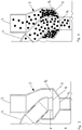
- FIG 1 shows an external perspective view of an exemplary dosing device for granular material according to an embodiment of the invention.
- the metering device comprises a housing 1, within which a conveyor device (not visible here) is rotatably mounted.
- the conveying device interacts with a housing wall or a guide element in such a way that granular material can be conveyed from a receiving area into a delivery area.
- An outlet opening is provided in the discharge area, through which the granular material can be discharged from the housing 1.
- the granular material discharged in this way can, for example, have a Figure 1 indicated connection line 2 are passed to a delivery device.
- the dispensing device can comprise, for example, a coulter.
- FIG. 1 a collection container 3 for granular material is shown.
- a return line 4 opens into the collecting container 3, which connects the collecting container 3 and the interior of the housing 1 to one another, so that grains of the granular material can be conveyed from the housing 1 into the collecting container 3 via the return line 4.
- Granular material for example seed
- This granular material, together with the granular material supplied via the return line 4, can form a seed supply or buffer within the collecting container 3.
- the granular material can then be introduced from the collecting container 3 via the side wall 6 of the housing 1 into the interior of the housing 1 via a feed device, which is not visible here, so that it is made available there for the conveying device.
- This invisible feed device is part of a pre-metering unit 7, which in Figure 1 is arranged below the collecting container 3.
- the collecting container 3 and the pre-metering unit 7 are connected here via a connecting line 8.
- the connecting line 8 connects to a funnel-shaped element 9, which is formed by a lower wall section of the collecting container 3.
- the connecting line 8 forms, as it were, a funnel neck to the funnel-shaped element 9.
- the funnel-shaped element 9 has an outlet opening (not visible here) which opens into the connecting line 8.
- a section 10 of the collecting container 3 Immediately above the funnel-shaped element 9 is a section 10 of the collecting container 3, in which a multiplicity of passage openings are provided, which form an air outlet grille or air outlet sieve. Through these air outlet openings or bores in section 10, it is possible to make the supply of granular material into the collecting container 3 at least partially self-regulating.
- a nursing system can be used to load the collecting container 3.
- the collecting container 3 can be connected to a central storage container via a pneumatic delivery channel.
- the delivery channel can be pressurized with an overpressure relative to the atmospheric pressure.
- there is an air flow via the pneumatic conveying channel and the air outlet openings in section 10 there is also a conveying of granular material, in particular seed, from the central storage container into the collecting container 3.
- the conveying air flow stops in the pneumatic conveying channel, so that the further supply of granular material from the central storage container via the opening 5 in the collecting container 3 stops.
- FIG 2 is a section through the exemplary metering device according to Figure 1 shown.
- the housing 1 in the interior of which the rotatably mounted conveyor 11 is shown schematically.
- Granular material can be discharged from the housing 1 via this outlet opening 12, in particular after it has been conveyed from the receiving device 11 into the feed area and thus metered.
- the conveying device 11 can serve in particular as a separating device, so that individual grains of the granular material are introduced into the connecting channel 2 via the outlet opening 12 at regular intervals.
- the axis of rotation of the conveyor 8 runs horizontally in this example. In operation of the metering device, the axis of rotation runs parallel to the agricultural soil to be worked.
- FIG. 2 parts of the pre-metering unit 7, which opens into the housing 1 via the side wall 6, can be seen. Shown is a rotor 13 designed as a screw conveyor, which is suitable for conveying granular material from the collecting container 3 into the interior of the housing 1.
- the axis of rotation of the rotor 13 is coaxial with the axis of rotation of the conveyor 11.
- the rotor 13 could also drive an internal thread which is arranged in the interior of the pre-metering unit 7.
- a motor or drive not shown, is provided to drive the conveyor 11.
- This motor or drive can also be used
- Driving the pre-metering unit 7, in particular the rotor 13, may be provided.
- the metering device can be designed such that the conveyor device rotates at a frequency between 5 Hz and 60 Hz.
- the conveying device By designing the conveying device with, for example, three centering slides, which are each designed for conveying a grain, a singulation frequency of 15 Hz to 180 Hz is made possible. As a result, very small distances between the deposited grains can be achieved.
- FIG. 2 The funnel-shaped element 9 and its outlet opening 14, which opens into the connecting line 8, can be seen.
- the outlet opening 14 is connected to the pre-metering unit 7 via the connecting line 8.
- the wall of the funnel-shaped element 9 widens conically from the outlet opening 14 to a feed opening 15.
- the mouth 16 of the return line 4 is arranged above the outlet opening 14.
- the mouth 16 of the return line 4 is arranged concentrically with the outlet opening 14. “Concentric” here means that the center or center of gravity of the mouth 16, when it is projected into the plane of the outlet opening 14, is equal to the center or center of gravity of the outlet opening 14.
- FIG 3 a cross section through an exemplary collecting container 3 is shown.
- the funnel-shaped element 9 with its outlet opening 14 and the inlet opening 15 surrounding the return line 4 in a ring.
- the mouth 16 of the return line 4 lying in one plane with the inlet opening 15 is arranged concentrically with the outlet opening 14.
- the center of the mouth 16, like the center of the outlet opening 14, thus lies on the longitudinal or symmetry axis of the funnel-shaped element 9.
- the connecting line 8 connects to the outlet opening 14 and forms a funnel neck to the funnel-shaped element 9.
- the return line 4 is partially arranged inside the collecting container 3.
- the line section 4 ' is arranged coaxially to the longitudinal or symmetry axis of the funnel-shaped element 9.
- the diameter of the mouth 16 is larger than the diameter of the outlet opening 14.
- Figure 4 shows the collection container 3 of the Figure 3 however with granular material incorporated therein.
- the conveyor 11 in the housing 1 of the metering device picks up granular material in a receiving area and then conveys it to the delivery area in such a way that a desired number of grains per unit time is dispensed via the outlet opening 12, usually a single grain. So that the separation can be carried out properly, a larger number of grains of the granular material must be provided in the receiving area of the conveyor.
- excess grains are separated out by interaction with the housing wall or a guide element. These separated grains can then be discharged from the housing 1 via the return line 4 and returned to the collecting container 3.
- These returned grains are introduced into the funnel-shaped element 9 due to the concentric arrangement of the mouth near the longitudinal or symmetry axis of the funnel-shaped element 9.
- Granular material which is introduced into the collecting container 3 via the inlet opening 5 via a refill system, only passes through the annular feed opening 15 of the funnel-shaped element 9 into an area with a greater distance from the longitudinal or symmetrical axis of the funnel-shaped element 9. As a result, these usually only reach in the area of the outlet opening 14 when the support effect via the central grains ceases. This in turn is usually the case when the return of the granular material via the return channel 4 is reduced or terminates.
- the conveying element of the pre-metering unit 7 can Figure 2 be designed such that it introduces ten grains of the granular material into the interior of the housing 1 with each revolution.
- one grain is removed from the ten grains supplied by the conveyor 11.
- the remaining nine grains are returned to the collecting container 3 via the return line 4.
- the returned nine grains initially slide into the pre-metering unit 7 via the outlet opening 14 and the connecting channel 8, while a grain slips out of the seed column of the storage container 3.
- 10 grains can be conveyed to the conveyor 11 again.
- FIG. 5 An alternative embodiment of an exemplary collecting container 3 is shown.
- This collecting container 3 has an inlet opening 5, through which, as described above, granular material can be introduced into the collecting container 3 from a refill system, not shown here.
- a return line likewise not shown here, opens into the collecting container 3 via the mouth 18.
- a discharge opening 17 is arranged at the bottom of the collecting container 3, via which the collecting container 3 is connected to a pre-metering unit 7.
- the pre-metering unit 7 can be designed and arranged as described above.
- the mouth 18 is arranged above the discharge opening 17 and overlaps it.
- the inlet opening 5 is arranged above an inclined plane 19, which partly forms the bottom of the collecting container 3.
- the collecting container 3 is also divided into two sub-chambers 21, 22 via a partition 20. Since the partition 20 does not extend to the bottom of the collecting container 3, a passage 23 is formed, through which granular material can reach the outlet opening 17 from the partial chamber 21.
- the arrangement of the openings shown can achieve that granular material introduced via the return line is preferred to granular material Material that is supplied via the inlet opening 5 can be brought out of the collecting container 3.
- the grain flow, which leads from the mouth 18 to the discharge opening 17, can block the slipping of granular material over the inclined plane 19. Only when this flow diminishes or stops, does granular material reach the outlet opening 17 via the inclined plane 19.
- FIG 6 A further alternative embodiment of an exemplary collecting container 3 is shown.
- This collecting container 3 also has an inlet opening 5, through which, as described above, granular material can be introduced into the collecting container 3 from a refill system, not shown here.
- a return line likewise not shown here, opens into the collecting container 3 via the mouth 18.
- a discharge opening 17 is here in contrast to the embodiment of FIG Figure 5 arranged in a side wall of the collecting container 3.
- Granular material can be brought into a pre-metering unit (not shown here) via the discharge opening 17.
- the collection container 3 comprises the Figure 6 two sub-chambers 21, 22 which are connected via a passage 23.
- the partition 20 is not a flat wall, but a curved one.
- the discharge opening 17 is arranged completely in the second partial chamber 22.
- a level P of granular material is formed during operation of the metering device, which level comes from the return line on the one hand and from the feed via the refill system on the other hand.
- the level P should neither be too high nor too low.
- the size of the level depends, among other things, on the flowability of the granular material, since the newly supplied granular material is fed via the inclined plane 19.
- the size of the passage 23 can be made adjustable by means of a closing slide 24 (adjusting slide).
- the closing slide 24 can be moved as indicated by the double arrow in FIG Figure 6 indicated in the vertical direction, so that the distance between the Bottom of the collecting container 3 and the lower edge of the closure slide 24 and thus the size of the passage 23 can be varied.
- a larger opening in the passage 23 can be selected than in the case of very good flowability (in the case of rape, for example).
- the slide valve 24 the flow behavior of different granular materials can be taken into account and the level P can be adjusted accordingly.
- an actuating element 25 as in FIG Figure 7A shown, used.
- This actuating element 25 is connected to the closing slide 24 and is guided out through an elongated hole 26 through the wall of the collecting container 3.
- the actuating element 25 can thus be operated from the outside, in particular can be moved continuously along the elongated hole 26.
- a fastening device, not shown in more detail, of the closure slide 24 can, for example, by force locking that the closure slide 24 remains in a set position.
- FIGS Figures 7B and 7C Two exemplary positions of the actuating element 25 are shown in FIGS Figures 7B and 7C shown.
- Figure 7B shows the lowest position of the actuating element 25 in the elongated hole 26. This position can correspond to a position of the closure slide 24, in which the size of the passage 23 becomes minimal. It is also possible that the closing slide 24 completely closes the passage 23 in this case.
- Figure 7C shows the uppermost position of the actuating element 25 in the elongated hole 26. This position can correspond to a position of the closure slide 24 in which the size of the passage 23 becomes maximum. It is also possible that the passage 23 is completely open in this case.
- FIG Figure 8 shows a further cross section of the embodiment of FIG Figure 6 . From this view it can be seen in particular that the closing slide 24 extends along the entire width of the passage 23 and the remaining size of the passage 23 is therefore determined by the distance between the lower edge of the closing slide 24 and the bottom of the collecting container 3.
- the locking slide 24 of this embodiment can be moved continuously. However, it is also conceivable to provide a locking slide which can only be locked in predetermined discrete positions.
- the predetermined discrete positions can correspond to different flow behavior and thus different granular materials.
- FIG 9 a perspective view of a further exemplary collecting container 3 is shown.
- the special feature of this exemplary embodiment lies in the fact that a non-return valve 27 is arranged in the collecting container in the region of the mouth 18 of the return line into the collecting container 3.
- the non-return valve 27 is arranged in particular between the mouth 18 and the discharge opening of the collecting container (not shown here).
- This check valve 27 serves to prevent or at least make it more difficult to convey granular material from the collecting container 3 via the return line into the housing of the metering device.
- the pivot axis 28 of the check valve 27 is in Figure 9 also hinted at.
- FIG 10A shows a cross section through the exemplary collecting container 3 of FIG Figure 9 .
- the check valve 27 is arranged in the open position in this case. In this position of the check valve 27, a transport of granular material in the transport direction indicated by the arrow A is possible. This transport direction A leads from the housing via the return line to the discharge opening 17.
- a stop 29 is provided in order to prevent the non-return flap 27 from contacting the inner wall of the collecting container 3. This ensures that there is a minimum engagement surface 30 for a flow opposite to direction A, so that the non-return flap 27 can be closed if the transport direction reverses for any reason.
- Figure 10B shows the check valve 27 in the blocking position, since there is a flow in direction B, which is opposite to the direction of transport A.
- a flow in direction B can occur, for example, if a nursing system is put into operation at the beginning of the processing, but no granular material has yet been arranged in the collecting container 3.
- the granular material supplied via the inlet opening 5 can be unhindered flow into the second chamber 22 and from there optionally further into the return line and the housing of the metering device. This is prevented by the check valve 27 in the locked position.
- a second stop 31 is provided in order to prevent the check valve 27 from pivoting beyond the blocking position in the opposite direction B.
- the first stop 29 and the second stop 31 are formed in one piece. Both stops are thus combined in an element which is rigidly connected to the check valve 27. However, it would also be conceivable that two separate stop elements are provided.
- Figure 11 shows a cross section through another exemplary collecting container 3.
- the guide elements 32, 33 are arranged on opposite inner sides of the collecting container 3, in particular the second partial chamber 22.
- the guide elements 32, 33 are wedge-shaped, the tips of the guide elements 32, 33 pointing in the direction of the desired transport direction A.
- the guide elements 32, 33 are arranged in a cascade manner, in particular the guide elements 33 are arranged offset with respect to the guide elements 32.
- Granular material which moves in the opposite direction B, tends to be guided through the guide elements 32, 33 to the side walls of the collecting container 3, where it is prevented from further movement in the opposite direction B by the guide elements 32, 33.
- the granular material becomes the passable center in the center of the Sub-chamber 22 directed so that transport to the discharge opening 17 is possible.
- two guide elements 32, 33 are provided on each side, but this is not restrictive. Fewer or more than two guide elements could also be provided per side.
- the Figures 12A and 12B each show a cross section through the housing of an exemplary metering device.
- a centering slide 34 can be seen here, which pushes granular material along a guide surface of a guide element 35 from a receiving area into a delivery area and thereby centers a grain by supporting or guiding it on both sides. Grains which are not centered and which are picked up in the receiving area and transported along the guide surface can consequently be rejected, so that the centered grain remains in the delivery area and can be passed on to a delivery element for placement on an agricultural area. In particular, exactly one grain can be guided centered by the centering slide.
- the metering device can thus be a separating device.
- a collecting space 37 extends into both sides of the guide element 35, into which separated grains reach. These separated grains can via a return line 4 (see for example Figure 1 ) get into a collection container.
- drivers 38 are provided in the collecting space 37 on both sides of the guide element 35.
- the drivers 38 are mounted on the centering slide 34, so that they can rotate together with the centering slide 34 about the common axis of rotation 36.
- Figure 12B shows a cross section through the housing of the exemplary dosing device of the Figure 12A , but in the delivery area of the conveyor.
- the guide element 35 has a changed shape in the delivery area.
- the guide element 35 has a ridge running in the direction of rotation.
- a separation of the granular material is further promoted by such a burr, since usually only one grain can be moved stably along the burr, namely the grain which is at least partially centered by the centering slide 34.
- the predetermined path along the The guide surface along which the centering slide 34 moves a grain centered runs along the ridge.
- the separated grains 39 are shown in the collecting space 37 and are pushed by the drivers 38 along the inner circumferential surface of the housing 1, which radially delimits the collecting space, until they are conveyed into the return line at the mouth of the return line into the housing of the metering device.
- FIG 13 shows a further cross section through a housing 1 of an exemplary metering device.
- the illustration is simplified in order to illustrate the functioning of the drivers.
- the return line 4, which opens into the housing 1, can be seen.
- the return line 4 leads tangentially into the housing 1, so that a tangential transition 40 is created.
- two rotatably mounted drivers 38 are shown.
- the direction of rotation is indicated by an arrow.
- Separated grains 39 of the granular material can be moved along the collecting space by the drivers 38 and finally conveyed into the return line 4. This is particularly advantageous if the rejected grains 39 have not received sufficient kinetic energy through the rejection themselves to leave the housing 1 via the return line 4.
- the catches 38 are made of a flexible material, for example rubber. This allows the drivers 38 to dodge the direction of rotation when they encounter a jamming grain.
- FIG 14 shows an alternative embodiment of the drivers 38.
- the drivers 38 are rigid.
- the drivers 38 comprise joints 42, the axes of which extend transversely to the direction of rotation. Therefore the outer part of the drivers 38 dodge the direction of rotation when a driver 38 hits a jamming grain 43.
- the drivers 38 are stretched because the centrifugal force counteracts pivoting about the axis of the joint.
- the funnel-shaped element can also be a separate element which is arranged in the interior of the collecting container.
Landscapes
- Life Sciences & Earth Sciences (AREA)
- Soil Sciences (AREA)
- Environmental Sciences (AREA)
- Filling Or Emptying Of Bunkers, Hoppers, And Tanks (AREA)
- Pretreatment Of Seeds And Plants (AREA)
- Sowing (AREA)
- Supply Of Fluid Materials To The Packaging Location (AREA)
Claims (15)
- Dispositif de dosage pour matériau granulaire, en particulier des semences, le dispositif de dosage comportant un dispositif de transport (11) monté de manière rotative dans un boîtier (1), lequel dispositif de transport coopère avec une paroi de boîtier ou un élément de guidage de telle sorte que du matériau granulaire puisse être transporté à partir d'une région de réception dans une région de distribution,
le boîtier (1) étant relié à un réservoir collecteur (3) pour fournir du matériau granulaire ;
une conduite de retour (4) menant du boîtier au réservoir collecteur (3) ;
le réservoir collecteur (3) pouvant être rempli de matériau granulaire par le biais d'une ouverture d'entrée (5) ;
caractérisé en ce que le matériau granulaire peut être introduit dans une unité de pré-dosage (7) par le biais d'une ouverture de sortie ou d'évacuation (14, 17) du réservoir collecteur (3) directement ou par le biais d'une conduite de liaison (8), laquelle unité de pré-dosage est réalisée de telle sorte qu'elle transporte du matériau granulaire par le biais d'une ouverture d'alimentation dans le boîtier (1) ; et
l'unité de pré-dosage (7) comportant un rotor (13) dont l'axe de rotation s'étend de manière coaxiale à l'axe de rotation du dispositif de transport (11). - Dispositif de dosage selon la revendication 1, dans lequel le réservoir collecteur (3) comporte un élément (9) en forme d'entonnoir, dans lequel l'élément (9) en forme d'entonnoir comporte une ouverture d'alimentation (15) et une ouverture de sortie (14) ; et
dans lequel un débouché (16) de la conduite de retour (4) dans le réservoir collecteur (3) est disposé concentriquement à l'ouverture de sortie (14) de l'élément (9) en forme d'entonnoir. - Dispositif de dosage selon la revendication 2, dans lequel le débouché (16) de la conduite de retour (4) est disposé à l'intérieur du réservoir collecteur (3) .
- Dispositif de dosage selon la revendication 2 ou 3, dans lequel l'élément (9) en forme d'entonnoir est formé par une partie de paroi du réservoir collecteur (3) .
- Dispositif de dosage selon l'une des revendications précédentes, dans lequel le matériau granulaire peut être transporté à partir du réservoir collecteur (3) dans l'unité de pré-dosage (7) sous l'effet de la gravité.
- Dispositif de dosage selon l'une des revendications précédentes, dans lequel un débouché (16 ; 18) de la conduite de retour (4) dans le réservoir collecteur (3) est disposé au-dessus de l'ouverture de sortie ou d'évacuation (14 ; 17) et chevauche celle-ci complètement ou partiellement.
- Dispositif de dosage selon la revendication 6, dans lequel le fond du réservoir collecteur (3) comporte un plan oblique (19) incliné vers l'ouverture d'évacuation (17), et dans lequel l'ouverture d'entrée (5) est disposée au-dessus du plan oblique (19).
- Dispositif de dosage selon la revendication 7, dans lequel le plan oblique (19) est directement adjacent à l'ouverture d'évacuation (17).
- Dispositif de dosage selon l'une des revendications précédentes 1 ou 5 à 8,
dans lequel l'alimentation de matériau granulaire introduit par le biais de l'ouverture d'entrée (5) jusqu'à l'ouverture d'évacuation (17) peut être réglée au moyen d'un tiroir de fermeture (24). - Dispositif de dosage selon l'une des revendications précédentes, dans lequel un ou plusieurs éléments sont prévus dans la conduite de retour et/ou dans le réservoir collecteur, lesquels empêchent ou entravent un transport de matériau granulaire à partir du réservoir collecteur (3) dans le boîtier (1) par le biais de la conduite de retour (4).
- Dispositif de dosage selon la revendication 10, dans lequel lesdits un ou plusieurs éléments comportent un clapet anti-retour (27).
- Dispositif de dosage selon la revendication 10 ou 11,
dans lequel lesdits un ou plusieurs éléments comportent des éléments de guidage cunéiformes (32, 33) dont les pointes sont orientées dans le sens de transport (A) souhaité qui mène du boîtier (1) au réservoir collecteur (3) par le biais de la conduite de retour (4) . - Dispositif de dosage selon l'une des revendications précédentes, le dispositif de dosage comportant au moins un élément d'entraînement (38) monté rotatif, au moyen duquel des grains (39) du matériau granulaire qui sont mis à l'écart dans un espace de collecte (37) peuvent être accélérés et consécutivement évacués par force centrifuge hors de l'espace de collecte (37) et transportés dans la conduite de retour (4).
- Dispositif de dosage selon la revendication 13, dans lequel ledit au moins un élément d'entraînement (38) est réalisé de telle sorte qu'il peut être dévié au moins partiellement en sens inverse à son sens de rotation.
- Semoir comportant un dispositif de dosage selon l'une des revendications précédentes.
Applications Claiming Priority (2)
| Application Number | Priority Date | Filing Date | Title |
|---|---|---|---|
| DE102015114150.7A DE102015114150A1 (de) | 2015-08-26 | 2015-08-26 | Sämaschine und Verfahren zum Betreiben einer Sämaschine |
| PCT/EP2016/069632 WO2017032691A1 (fr) | 2015-08-26 | 2016-08-18 | Dispositif de dosage de matière granulaire à contenant de recueil |
Publications (2)
| Publication Number | Publication Date |
|---|---|
| EP3340765A1 EP3340765A1 (fr) | 2018-07-04 |
| EP3340765B1 true EP3340765B1 (fr) | 2020-04-15 |
Family
ID=56855417
Family Applications (1)
| Application Number | Title | Priority Date | Filing Date |
|---|---|---|---|
| EP16760403.2A Active EP3340765B1 (fr) | 2015-08-26 | 2016-08-18 | Dispositif de dosage pour matériel granulaire avec réservoir collecteur |
Country Status (5)
| Country | Link |
|---|---|
| EP (1) | EP3340765B1 (fr) |
| DE (1) | DE102015114150A1 (fr) |
| EA (1) | EA035922B1 (fr) |
| UA (1) | UA121897C2 (fr) |
| WO (1) | WO2017032691A1 (fr) |
Families Citing this family (4)
| Publication number | Priority date | Publication date | Assignee | Title |
|---|---|---|---|---|
| DE102016117135A1 (de) * | 2016-09-13 | 2018-03-15 | Amazonen-Werke H. Dreyer Gmbh & Co. Kg | Dosiervorrichtung mit Vordosierung und axialer Zuführung |
| DE102019108067A1 (de) * | 2019-03-28 | 2020-10-01 | Amazonen-Werke H. Dreyer Gmbh & Co. Kg | Dosiervorrichtung für granulares Material |
| DE102019117555A1 (de) * | 2019-06-28 | 2020-12-31 | Amazonen-Werke H. Dreyer Gmbh & Co. Kg | Portioniervorrichtung für chemisches Granulat |
| DE102021108172A1 (de) * | 2021-03-31 | 2022-10-06 | Amazonen-Werke H. Dreyer SE & Co. KG | Ausbringaggregat für eine landwirtschaftliche Ausbringmaschine |
Family Cites Families (5)
| Publication number | Priority date | Publication date | Assignee | Title |
|---|---|---|---|---|
| DD242547A1 (de) * | 1985-11-14 | 1987-02-04 | Mech Landwirtsch Forschzent | Vorrichtung zum vereinzeln und abgeben von koernigem gut |
| DE29623398U1 (de) * | 1995-09-15 | 1998-04-23 | Amazonen-Werke H. Dreyer Gmbh & Co Kg, 49205 Hasbergen | Landwirtschaftliche Verteilmaschine |
| AU2003904353A0 (en) * | 2003-08-05 | 2003-08-28 | Holly, John | Seed distribution method and apparatus |
| DE102012105048A1 (de) | 2012-06-12 | 2013-12-12 | Horsch Maschinen Gmbh | Verteilaggregat für körniges Gut, insbesondere Säaggregat |
| US9901026B2 (en) * | 2013-09-05 | 2018-02-27 | Kinze Manufacturing, Inc. | Multiple agricultural product application method and systems |
-
2015
- 2015-08-26 DE DE102015114150.7A patent/DE102015114150A1/de not_active Withdrawn
-
2016
- 2016-08-18 UA UAA201802581A patent/UA121897C2/uk unknown
- 2016-08-18 EP EP16760403.2A patent/EP3340765B1/fr active Active
- 2016-08-18 EA EA201890437A patent/EA035922B1/ru not_active IP Right Cessation
- 2016-08-18 WO PCT/EP2016/069632 patent/WO2017032691A1/fr active Application Filing
Non-Patent Citations (1)
| Title |
|---|
| None * |
Also Published As
| Publication number | Publication date |
|---|---|
| EP3340765A1 (fr) | 2018-07-04 |
| EA201890437A1 (ru) | 2018-10-31 |
| UA121897C2 (uk) | 2020-08-10 |
| DE102015114150A1 (de) | 2017-03-02 |
| EA035922B1 (ru) | 2020-09-01 |
| WO2017032691A1 (fr) | 2017-03-02 |
Similar Documents
| Publication | Publication Date | Title |
|---|---|---|
| EP2832200B1 (fr) | Procédé et dispositif de dosage de matériel granulaire | |
| EP3026998B1 (fr) | Procédé et dispositif de dosage de matériel granulaire | |
| EP3440908B1 (fr) | Dispositif de séparation pour matériau granulaire avec ensemble de conversion | |
| EP3412126B1 (fr) | Boîtier de distribution pour matériel granulaire, en particulier semoir | |
| EP3340765B1 (fr) | Dispositif de dosage pour matériel granulaire avec réservoir collecteur | |
| EP3050418A1 (fr) | Systeme de dosage d'une machine agricole | |
| EP3135088B1 (fr) | Dispositif de dosage pour materiau granulaire comprenant un pre-dosage axial | |
| EP3340763B1 (fr) | Dispositif de dosage de matière granulaire avec une unité de pré-dosage | |
| EP3352557B1 (fr) | Procédé et dispositif pour la distribution de matériel granulaire à un nombre variable des conduits | |
| DE102015114145A1 (de) | Dosiervorrichtung für granulares Material | |
| EP2805596A1 (fr) | Semoir | |
| DE102015114146A1 (de) | Dosiervorrichtung für granulares Material mit pneumatischer Nachfüllung | |
| EP3292748B1 (fr) | Dispositif de dosage avec des chambres de collection des graines séparées | |
| EP3704923B1 (fr) | Dispositif pour un semoir agricole, procédé de séparation des semences dans un dispositif pour un semoir agricole ainsi que semoir | |
| DE102015114151A1 (de) | Dosiervorrichtung für granulares Material mit Pufferstärkenmessung | |
| EP3108733B1 (fr) | Dispositif de transport a flux d'air ameliore de materiau granulaire a epandre sur une surface agricole | |
| DE102015114153A1 (de) | Dosiervorrichtung für granulares Material mit Abbremsmitteln | |
| EP3108734B1 (fr) | Dispositif de transport pneumatique ameliore de materiau granulaire a epandre sur une surface agricole | |
| DE102015114148A1 (de) | Dosiervorrichtung für granulares Material mit Schleuse | |
| EP3238520A1 (fr) | Semoir ayant une évacuation d'air améliorée |
Legal Events
| Date | Code | Title | Description |
|---|---|---|---|
| STAA | Information on the status of an ep patent application or granted ep patent |
Free format text: STATUS: THE INTERNATIONAL PUBLICATION HAS BEEN MADE |
|
| PUAI | Public reference made under article 153(3) epc to a published international application that has entered the european phase |
Free format text: ORIGINAL CODE: 0009012 |
|
| STAA | Information on the status of an ep patent application or granted ep patent |
Free format text: STATUS: REQUEST FOR EXAMINATION WAS MADE |
|
| 17P | Request for examination filed |
Effective date: 20180313 |
|
| AK | Designated contracting states |
Kind code of ref document: A1 Designated state(s): AL AT BE BG CH CY CZ DE DK EE ES FI FR GB GR HR HU IE IS IT LI LT LU LV MC MK MT NL NO PL PT RO RS SE SI SK SM TR |
|
| AX | Request for extension of the european patent |
Extension state: BA ME |
|
| DAV | Request for validation of the european patent (deleted) | ||
| DAX | Request for extension of the european patent (deleted) | ||
| GRAP | Despatch of communication of intention to grant a patent |
Free format text: ORIGINAL CODE: EPIDOSNIGR1 |
|
| STAA | Information on the status of an ep patent application or granted ep patent |
Free format text: STATUS: GRANT OF PATENT IS INTENDED |
|
| INTG | Intention to grant announced |
Effective date: 20191210 |
|
| GRAS | Grant fee paid |
Free format text: ORIGINAL CODE: EPIDOSNIGR3 |
|
| GRAA | (expected) grant |
Free format text: ORIGINAL CODE: 0009210 |
|
| STAA | Information on the status of an ep patent application or granted ep patent |
Free format text: STATUS: THE PATENT HAS BEEN GRANTED |
|
| AK | Designated contracting states |
Kind code of ref document: B1 Designated state(s): AL AT BE BG CH CY CZ DE DK EE ES FI FR GB GR HR HU IE IS IT LI LT LU LV MC MK MT NL NO PL PT RO RS SE SI SK SM TR |
|
| REG | Reference to a national code |
Ref country code: CH Ref legal event code: EP |
|
| REG | Reference to a national code |
Ref country code: DE Ref legal event code: R096 Ref document number: 502016009573 Country of ref document: DE |
|
| REG | Reference to a national code |
Ref country code: IE Ref legal event code: FG4D Free format text: LANGUAGE OF EP DOCUMENT: GERMAN |
|
| REG | Reference to a national code |
Ref country code: AT Ref legal event code: REF Ref document number: 1256196 Country of ref document: AT Kind code of ref document: T Effective date: 20200515 |
|
| REG | Reference to a national code |
Ref country code: NL Ref legal event code: FP |
|
| REG | Reference to a national code |
Ref country code: LT Ref legal event code: MG4D |
|
| PG25 | Lapsed in a contracting state [announced via postgrant information from national office to epo] |
Ref country code: IS Free format text: LAPSE BECAUSE OF FAILURE TO SUBMIT A TRANSLATION OF THE DESCRIPTION OR TO PAY THE FEE WITHIN THE PRESCRIBED TIME-LIMIT Effective date: 20200815 Ref country code: SE Free format text: LAPSE BECAUSE OF FAILURE TO SUBMIT A TRANSLATION OF THE DESCRIPTION OR TO PAY THE FEE WITHIN THE PRESCRIBED TIME-LIMIT Effective date: 20200415 Ref country code: PT Free format text: LAPSE BECAUSE OF FAILURE TO SUBMIT A TRANSLATION OF THE DESCRIPTION OR TO PAY THE FEE WITHIN THE PRESCRIBED TIME-LIMIT Effective date: 20200817 Ref country code: LT Free format text: LAPSE BECAUSE OF FAILURE TO SUBMIT A TRANSLATION OF THE DESCRIPTION OR TO PAY THE FEE WITHIN THE PRESCRIBED TIME-LIMIT Effective date: 20200415 Ref country code: FI Free format text: LAPSE BECAUSE OF FAILURE TO SUBMIT A TRANSLATION OF THE DESCRIPTION OR TO PAY THE FEE WITHIN THE PRESCRIBED TIME-LIMIT Effective date: 20200415 Ref country code: GR Free format text: LAPSE BECAUSE OF FAILURE TO SUBMIT A TRANSLATION OF THE DESCRIPTION OR TO PAY THE FEE WITHIN THE PRESCRIBED TIME-LIMIT Effective date: 20200716 Ref country code: NO Free format text: LAPSE BECAUSE OF FAILURE TO SUBMIT A TRANSLATION OF THE DESCRIPTION OR TO PAY THE FEE WITHIN THE PRESCRIBED TIME-LIMIT Effective date: 20200715 |
|
| PG25 | Lapsed in a contracting state [announced via postgrant information from national office to epo] |
Ref country code: LV Free format text: LAPSE BECAUSE OF FAILURE TO SUBMIT A TRANSLATION OF THE DESCRIPTION OR TO PAY THE FEE WITHIN THE PRESCRIBED TIME-LIMIT Effective date: 20200415 Ref country code: RS Free format text: LAPSE BECAUSE OF FAILURE TO SUBMIT A TRANSLATION OF THE DESCRIPTION OR TO PAY THE FEE WITHIN THE PRESCRIBED TIME-LIMIT Effective date: 20200415 Ref country code: BG Free format text: LAPSE BECAUSE OF FAILURE TO SUBMIT A TRANSLATION OF THE DESCRIPTION OR TO PAY THE FEE WITHIN THE PRESCRIBED TIME-LIMIT Effective date: 20200715 Ref country code: HR Free format text: LAPSE BECAUSE OF FAILURE TO SUBMIT A TRANSLATION OF THE DESCRIPTION OR TO PAY THE FEE WITHIN THE PRESCRIBED TIME-LIMIT Effective date: 20200415 |
|
| PG25 | Lapsed in a contracting state [announced via postgrant information from national office to epo] |
Ref country code: AL Free format text: LAPSE BECAUSE OF FAILURE TO SUBMIT A TRANSLATION OF THE DESCRIPTION OR TO PAY THE FEE WITHIN THE PRESCRIBED TIME-LIMIT Effective date: 20200415 |
|
| REG | Reference to a national code |
Ref country code: DE Ref legal event code: R097 Ref document number: 502016009573 Country of ref document: DE |
|
| PG25 | Lapsed in a contracting state [announced via postgrant information from national office to epo] |
Ref country code: DK Free format text: LAPSE BECAUSE OF FAILURE TO SUBMIT A TRANSLATION OF THE DESCRIPTION OR TO PAY THE FEE WITHIN THE PRESCRIBED TIME-LIMIT Effective date: 20200415 Ref country code: SM Free format text: LAPSE BECAUSE OF FAILURE TO SUBMIT A TRANSLATION OF THE DESCRIPTION OR TO PAY THE FEE WITHIN THE PRESCRIBED TIME-LIMIT Effective date: 20200415 Ref country code: EE Free format text: LAPSE BECAUSE OF FAILURE TO SUBMIT A TRANSLATION OF THE DESCRIPTION OR TO PAY THE FEE WITHIN THE PRESCRIBED TIME-LIMIT Effective date: 20200415 Ref country code: IT Free format text: LAPSE BECAUSE OF FAILURE TO SUBMIT A TRANSLATION OF THE DESCRIPTION OR TO PAY THE FEE WITHIN THE PRESCRIBED TIME-LIMIT Effective date: 20200415 Ref country code: CZ Free format text: LAPSE BECAUSE OF FAILURE TO SUBMIT A TRANSLATION OF THE DESCRIPTION OR TO PAY THE FEE WITHIN THE PRESCRIBED TIME-LIMIT Effective date: 20200415 Ref country code: RO Free format text: LAPSE BECAUSE OF FAILURE TO SUBMIT A TRANSLATION OF THE DESCRIPTION OR TO PAY THE FEE WITHIN THE PRESCRIBED TIME-LIMIT Effective date: 20200415 Ref country code: ES Free format text: LAPSE BECAUSE OF FAILURE TO SUBMIT A TRANSLATION OF THE DESCRIPTION OR TO PAY THE FEE WITHIN THE PRESCRIBED TIME-LIMIT Effective date: 20200415 |
|
| PLBE | No opposition filed within time limit |
Free format text: ORIGINAL CODE: 0009261 |
|
| STAA | Information on the status of an ep patent application or granted ep patent |
Free format text: STATUS: NO OPPOSITION FILED WITHIN TIME LIMIT |
|
| PG25 | Lapsed in a contracting state [announced via postgrant information from national office to epo] |
Ref country code: PL Free format text: LAPSE BECAUSE OF FAILURE TO SUBMIT A TRANSLATION OF THE DESCRIPTION OR TO PAY THE FEE WITHIN THE PRESCRIBED TIME-LIMIT Effective date: 20200415 Ref country code: SK Free format text: LAPSE BECAUSE OF FAILURE TO SUBMIT A TRANSLATION OF THE DESCRIPTION OR TO PAY THE FEE WITHIN THE PRESCRIBED TIME-LIMIT Effective date: 20200415 |
|
| 26N | No opposition filed |
Effective date: 20210118 |
|
| PG25 | Lapsed in a contracting state [announced via postgrant information from national office to epo] |
Ref country code: MC Free format text: LAPSE BECAUSE OF FAILURE TO SUBMIT A TRANSLATION OF THE DESCRIPTION OR TO PAY THE FEE WITHIN THE PRESCRIBED TIME-LIMIT Effective date: 20200415 |
|
| REG | Reference to a national code |
Ref country code: CH Ref legal event code: PL |
|
| GBPC | Gb: european patent ceased through non-payment of renewal fee |
Effective date: 20200818 |
|
| PG25 | Lapsed in a contracting state [announced via postgrant information from national office to epo] |
Ref country code: LI Free format text: LAPSE BECAUSE OF NON-PAYMENT OF DUE FEES Effective date: 20200831 Ref country code: LU Free format text: LAPSE BECAUSE OF NON-PAYMENT OF DUE FEES Effective date: 20200818 Ref country code: CH Free format text: LAPSE BECAUSE OF NON-PAYMENT OF DUE FEES Effective date: 20200831 |
|
| REG | Reference to a national code |
Ref country code: DE Ref legal event code: R081 Ref document number: 502016009573 Country of ref document: DE Owner name: AMAZONEN-WERKE H. DREYER SE & CO. KG, DE Free format text: FORMER OWNER: AMAZONEN-WERKE H. DREYER GMBH & CO. KG, 49205 HASBERGEN, DE |
|
| REG | Reference to a national code |
Ref country code: BE Ref legal event code: MM Effective date: 20200831 |
|
| PG25 | Lapsed in a contracting state [announced via postgrant information from national office to epo] |
Ref country code: SI Free format text: LAPSE BECAUSE OF FAILURE TO SUBMIT A TRANSLATION OF THE DESCRIPTION OR TO PAY THE FEE WITHIN THE PRESCRIBED TIME-LIMIT Effective date: 20200415 |
|
| PG25 | Lapsed in a contracting state [announced via postgrant information from national office to epo] |
Ref country code: BE Free format text: LAPSE BECAUSE OF NON-PAYMENT OF DUE FEES Effective date: 20200831 Ref country code: IE Free format text: LAPSE BECAUSE OF NON-PAYMENT OF DUE FEES Effective date: 20200818 Ref country code: GB Free format text: LAPSE BECAUSE OF NON-PAYMENT OF DUE FEES Effective date: 20200818 |
|
| PG25 | Lapsed in a contracting state [announced via postgrant information from national office to epo] |
Ref country code: TR Free format text: LAPSE BECAUSE OF FAILURE TO SUBMIT A TRANSLATION OF THE DESCRIPTION OR TO PAY THE FEE WITHIN THE PRESCRIBED TIME-LIMIT Effective date: 20200415 Ref country code: MT Free format text: LAPSE BECAUSE OF FAILURE TO SUBMIT A TRANSLATION OF THE DESCRIPTION OR TO PAY THE FEE WITHIN THE PRESCRIBED TIME-LIMIT Effective date: 20200415 Ref country code: CY Free format text: LAPSE BECAUSE OF FAILURE TO SUBMIT A TRANSLATION OF THE DESCRIPTION OR TO PAY THE FEE WITHIN THE PRESCRIBED TIME-LIMIT Effective date: 20200415 |
|
| PG25 | Lapsed in a contracting state [announced via postgrant information from national office to epo] |
Ref country code: MK Free format text: LAPSE BECAUSE OF FAILURE TO SUBMIT A TRANSLATION OF THE DESCRIPTION OR TO PAY THE FEE WITHIN THE PRESCRIBED TIME-LIMIT Effective date: 20200415 |
|
| P01 | Opt-out of the competence of the unified patent court (upc) registered |
Effective date: 20230523 |
|
| PGFP | Annual fee paid to national office [announced via postgrant information from national office to epo] |
Ref country code: AT Payment date: 20230725 Year of fee payment: 8 |
|
| PGFP | Annual fee paid to national office [announced via postgrant information from national office to epo] |
Ref country code: DE Payment date: 20230620 Year of fee payment: 8 |
|
| PGFP | Annual fee paid to national office [announced via postgrant information from national office to epo] |
Ref country code: NL Payment date: 20240613 Year of fee payment: 9 |
|
| PGFP | Annual fee paid to national office [announced via postgrant information from national office to epo] |
Ref country code: FR Payment date: 20240611 Year of fee payment: 9 |