EP3340765B1 - Dosing device for granular material with collecting bin - Google Patents
Dosing device for granular material with collecting bin Download PDFInfo
- Publication number
- EP3340765B1 EP3340765B1 EP16760403.2A EP16760403A EP3340765B1 EP 3340765 B1 EP3340765 B1 EP 3340765B1 EP 16760403 A EP16760403 A EP 16760403A EP 3340765 B1 EP3340765 B1 EP 3340765B1
- Authority
- EP
- European Patent Office
- Prior art keywords
- collecting container
- granular material
- return line
- housing
- dispensing apparatus
- Prior art date
- Legal status (The legal status is an assumption and is not a legal conclusion. Google has not performed a legal analysis and makes no representation as to the accuracy of the status listed.)
- Active
Links
- 239000008187 granular material Substances 0.000 title claims description 130
- 230000005484 gravity Effects 0.000 claims description 12
- 230000009471 action Effects 0.000 claims description 4
- 238000007599 discharging Methods 0.000 claims 1
- 235000013339 cereals Nutrition 0.000 description 119
- 238000000926 separation method Methods 0.000 description 13
- 238000005192 partition Methods 0.000 description 10
- 230000000474 nursing effect Effects 0.000 description 9
- 230000007423 decrease Effects 0.000 description 8
- 230000000694 effects Effects 0.000 description 8
- 239000000463 material Substances 0.000 description 8
- 230000000903 blocking effect Effects 0.000 description 5
- 241000209219 Hordeum Species 0.000 description 4
- 235000007340 Hordeum vulgare Nutrition 0.000 description 4
- 230000008859 change Effects 0.000 description 4
- 230000003247 decreasing effect Effects 0.000 description 4
- 230000007935 neutral effect Effects 0.000 description 4
- 240000002791 Brassica napus Species 0.000 description 3
- 235000004977 Brassica sinapistrum Nutrition 0.000 description 3
- 230000002452 interceptive effect Effects 0.000 description 3
- 235000007319 Avena orientalis Nutrition 0.000 description 2
- 244000075850 Avena orientalis Species 0.000 description 2
- 241000209056 Secale Species 0.000 description 2
- 235000007238 Secale cereale Nutrition 0.000 description 2
- 241000209140 Triticum Species 0.000 description 2
- 235000021307 Triticum Nutrition 0.000 description 2
- 230000008901 benefit Effects 0.000 description 2
- 230000003993 interaction Effects 0.000 description 2
- 240000008042 Zea mays Species 0.000 description 1
- 235000016383 Zea mays subsp huehuetenangensis Nutrition 0.000 description 1
- 235000002017 Zea mays subsp mays Nutrition 0.000 description 1
- 230000007547 defect Effects 0.000 description 1
- 230000001419 dependent effect Effects 0.000 description 1
- 230000001627 detrimental effect Effects 0.000 description 1
- 239000003337 fertilizer Substances 0.000 description 1
- 235000009973 maize Nutrition 0.000 description 1
- 238000005457 optimization Methods 0.000 description 1
- 239000000575 pesticide Substances 0.000 description 1
- 230000001105 regulatory effect Effects 0.000 description 1
- 239000002689 soil Substances 0.000 description 1
- 230000007704 transition Effects 0.000 description 1
Images


Classifications
-
- A—HUMAN NECESSITIES
- A01—AGRICULTURE; FORESTRY; ANIMAL HUSBANDRY; HUNTING; TRAPPING; FISHING
- A01C—PLANTING; SOWING; FERTILISING
- A01C7/00—Sowing
- A01C7/04—Single-grain seeders with or without suction devices
Definitions
- the invention relates to a metering device for granular material, in particular for seeds.
- Devices of this type are used in agricultural seed drills in order to forward seeds in defined quantities to delivery elements and then to deposit them on an agricultural area. For certain seeds, for example maize, it is desirable to deposit individual grains at predetermined intervals.
- known metering devices use a separating drum or separating disc to which a pressure difference can be applied.
- the separating drum or separating disc comprises perforations arranged in rows of perforations, on which the seed can accumulate, whereby there is a separation.
- a metering device specifically directed to such an insert is therefore from the DE 10 2012 105 048 A1 known.
- This metering device comprises a conveyor device which rotates concentrically in a housing and connects approximately tangentially to an inner lateral surface of the housing. Pockets are formed in the conveyor in which seeds of the seed are pressed and conveyed in a circle until only a single grain remains in the pocket in a further area of the housing due to a changed contour of the inner surface area of the housing and under the influence of centrifugal force, while excess grains are separated and removed funding can be returned to a first housing area.
- the known systems In order to introduce the granular material into the metering device, the known systems usually use a central metering device in connection with a distributor head. Starting from the distributor head, a connecting line leads to the housing of the metering device.
- the object of the invention is therefore to provide a metering device for granular material, in particular seed, which enables improved metering quality, in particular separating quality.
- the housing is connected to a collecting container for providing granular material and leads a return line from the housing into the collecting container.
- a reservoir of granular material can be provided for the conveyor in the collecting container, from where it can be directed to the conveyor. Since a return line leads from the housing into the collecting container, separated grains of the granular material can be discharged from the housing of the conveying device and conveyed into the collecting container. These separated grains therefore do not contribute to an unnecessary enlargement of the buffer in the housing, so that the dosing quality, in particular the separation quality, can be improved.
- the granular material can in particular be seed, but alternatively or additionally, it can also be granular fertilizer or granular Pesticide.
- the seeds can in particular be seeds for cereals, such as wheat, rye, barley, oats or rapeseed.
- the return line can lead from the housing into the collection container in such a way that granular material can be conveyed from the inside of the housing via the return line into the collection container.
- the collection container can be filled with granular material via an inlet opening, in particular via a refill system, such as a nursing system.
- the collecting container can be designed in such a way that granular material introduced via the return line can be discharged from the collecting container, preferably over granular material which is supplied via the inlet opening. It can thereby be achieved that the grains of the granular material which are separated out during the dosing are first used.
- the supply of granular material via a refill system can then be controlled or regulated as required.
- the collecting container can in particular have an outlet or discharge opening, via which granular material can be discharged from the collecting container, an opening of the return line in the collecting container being arranged above the outlet or discharge opening and overlapping it completely or partially. In this way, preference can be given to the material introduced via the return line.
- the indication "above” refers here in particular to the position when the metering device is in operation.
- the collecting container can comprise a funnel-shaped element, the funnel-shaped element comprising a feed opening and an outlet opening, and an opening of the return line in the collecting container being arranged concentrically to the outlet opening of the funnel-shaped element.
- the outlet opening of the funnel-shaped element can correspond to or be connected to the above-mentioned discharge opening.
- This embodiment takes advantage of the knowledge that granular material from a funnel-shaped container initially runs out of a central region along the axis of symmetry. Only when the support effect through the central grains that run out, grains run from the outside areas. Because a mouth of the return line in the collecting container is arranged concentrically to an outlet opening of the funnel-shaped element, it is therefore possible that the grains of the granular material originating from the housing are first brought back into the housing via the return line and the outlet opening, and be there again for the conveyor. Only when the flow of granular material via the return line subsides does grain follow from the grain buffer arranged in the collecting container.
- the measures mentioned make it possible to feed granular material to the conveyor as required. As a result, the quality of the dosage, in particular the singulation, can be increased.
- a “funnel-shaped element” can be understood here to mean, in particular, an element in which the outlet opening is connected to the feed opening via a, in particular conically, widening wall.
- the funnel-shaped element can in particular be designed in such a way that the feed opening is made larger than the outlet opening, the feed opening therefore in particular has a larger diameter than the outlet opening.
- the funnel-shaped element can be rotationally symmetrical, in particular with respect to a longitudinal or symmetry axis.
- the term “concentric” can be understood here in particular to mean that the center or center of gravity of the mouth of the return line is equal to the center or center of gravity of the outlet opening if the mouth and the outlet opening are projected into a common plane.
- the common plane can in particular be perpendicular to the longitudinal or symmetry axis of the funnel-shaped element.
- the term “concentric” can be understood to mean that the center or center of gravity of the mouth of the return line and the center or center of gravity of the outlet opening are both on the longitudinal or symmetrical axis of the funnel-shaped element.
- the mouth of the return line can lie in one plane with the feed opening.
- the mouth of the return line can be arranged, in particular, above the outlet opening during operation of the metering device.
- the mouth of the return line can be arranged in particular in the interior of the collecting container.
- the return line itself can thus be partially arranged inside the collecting container.
- a portion of the part of the return line which is arranged in the collecting container can be arranged coaxially to the longitudinal axis or axis of symmetry of the funnel-shaped element.
- the funnel-shaped element can in particular be formed by a wall section of the collecting container.
- the collecting container itself can be funnel-shaped at least in sections.
- the collecting container has an inlet opening mentioned above, through which granular material can be introduced into the collecting container.
- the inlet opening can be arranged, in particular, above the feed opening and the outlet opening of the funnel-shaped element. This allows granular material to enter the funnel-shaped element via the feed opening under the action of gravity.
- the feed opening can be annular and in particular surround the mouth of the return line.
- the grains supplied from the outside are located at a greater radial distance in the funnel-shaped element than the grains which are introduced from the housing into the funnel-shaped element via the return line.
- the grains introduced via the return line can therefore preferably be discharged via the outlet opening.
- the collecting container can be connected to a refill system, in particular a nursing system, via the inlet opening.
- the nursing system can comprise a central storage container for granular material, the central storage container being connected to the inlet opening of the collecting container via a pneumatic conveying channel.
- the nursing system can also include a blower with which a conveying air flow can be generated in the pneumatic conveying duct.
- the inlet opening of the collecting container can also be connected to a distributor head.
- the granular material can be introduced into a pre-metering unit directly via the outlet or discharge opening or via a connecting line, the pre-metering unit being designed such that it conveys granular material into the housing via a supply opening.
- the feed opening can in particular be arranged in a wall of the housing.
- the connecting line optionally adjoining the outlet opening can form a funnel neck to the funnel-shaped element.
- the funnel neck can be cylindrical, in particular circular cylindrical. However, it is also possible for the side wall of the funnel neck to be conical, for example.
- the pre-metering unit comprises a rotor, the axis of rotation of which runs coaxially to the axis of rotation of the conveying device.
- the rotor can be connected to conveying elements which convey the granular material into the housing of the metering device.
- the granular material can be conveyed from the collecting container into the pre-metering unit under the action of gravity.
- the outlet opening of the funnel-shaped element can be arranged, in particular, above the pre-metering unit during operation. In this way, particularly simple conveyance of the granular material is possible.
- the diameter of the mouth of the return line can be greater than or equal to the diameter of the outlet opening. It can thereby be achieved to a particular degree that material introduced into the collecting container via the return line is preferably discharged via the outlet opening. Only when the return of granular material via the return line is reduced or stops, is granular material discharged through the outlet opening, which is then added to the collection container via the refill system was introduced, so it was not previously in the housing of the metering device.
- the bottom of the collecting container can contain a plane leading to the discharge opening, which in a particularly advantageous embodiment is designed as an inclined plane, the inlet opening being arranged above the plane.
- the floor can also be at least partially in the form of an inclined plane.
- the granular material introduced into the collecting container via a refill system first reaches the inclined plane, from where it can slide to the discharge opening.
- this grain flow can prevent or reduce the sliding of grains on the inclined plane. Only when this grain flow subsides can grains get from the inclined plane into the discharge opening.
- the angle at which the inclined plane is inclined to the horizontal can be between 10 ° and 45 °.
- the inclined plane can in particular directly adjoin the discharge opening.
- the mouth of the return line into the collecting container can be arranged in particular above the discharge opening and overlap it completely or partially.
- the extent of the mouth of the return line can in particular be greater than the extent of the discharge opening.
- the “extension” can be understood in particular to mean the maximum or average extension of the mouth or the discharge opening or its diameter.
- the discharge opening is not arranged on the bottom of the collecting container, but in a side wall of the collecting container is. In this case, the mouth of the return line does not necessarily overlap the discharge opening.
- the collecting container can be divided into two subchambers by a partition, the inlet opening opening into a first subchamber and the mouth of the return line opening into a second subchamber.
- the first and the second partial chamber can be connected via a passage.
- the passage can in particular be formed in that the partition is spaced from the bottom of the collecting container. A passage opening in the partition would also be conceivable.
- the partition can be a flat wall, the two partial chambers being arranged on opposite sides of the partition.
- the partition can also have a more complex geometry.
- the partition wall can be curved and / or be part of the outer wall of the collecting container.
- the first partial chamber can be an extension of the delivery line, which leads to the inlet opening as part of the refill system.
- the second sub-chamber can accordingly be an extension of the return line, which leads from the housing to the mouth of the return line mentioned above.
- the discharge opening can in particular be arranged in the second sub-chamber, in particular completely.
- the supply of granular material introduced via the inlet opening to the discharge opening can be adjustable by means of a closing slide (adjusting slide).
- the size of the passage between the two subchambers can be adjustable via a slide valve.
- the locking slide can in particular be actuated manually.
- an actuating element can be guided outwards through the wall of the collecting container, so that the actuating element can be operated from the outside.
- the actuating element can in particular be rigidly coupled to the closing slide, so that a movement of the actuating element can be transmitted to the closing slide.
- Can in the wall of the collecting container a through opening, in particular an elongated hole, can be provided in which the actuating element can be moved in a guided manner.
- This adjustability allows the level of granular material at the discharge opening to be influenced or controlled.
- the flowability of the granular material can be taken into account. For example, if the flowability is poor (for example in the case of pickled barley), the closure slide can be opened widely, if necessary completely, while if the flowability is very good (for example in the case of rapeseed) a small opening is set. This prevents the level from being too low in the case of poor flowability, which could lead to defects, or the level being too high when the flowability is good, which can lead to an increased drive power for the metering.
- the position of the closing slide can in particular be continuously changeable. This also allows the passage size to be continuously adjusted.
- the metering device can be designed such that the position of the closure slide can only be changed between discrete positions. The discrete positions can correspond to different flow capacities and thus different types of granular material. In the case of continuous adjustability, corresponding markings can be provided on the collecting container, which indicate the optimal position of the closure slide for given granular materials.
- At least one air outlet opening can be arranged in a section of the wall of the collecting container.
- a plurality of air outlet openings can be arranged in the form of an air outlet grille or an air outlet sieve.
- the wall section of the collecting container with the at least one air outlet opening can be arranged in particular above the funnel-shaped element, in particular adjoining the funnel-shaped element directly above.
- the wall section of the collecting container with the at least one air outlet opening can also be arranged in a side wall of the collecting container which is arranged above the inclined plane, in particular in a side wall of the first partial chamber.
- the conveying air flow for conveying granular material into the collecting container can be influenced via the at least one air outlet opening.
- the at least one air outlet opening can be blocked by granular material in the collecting container.
- the conveying air flow can be weakened in such a way that there is no further conveyance of granular material to the collecting container.
- At least one air outlet opening can cooperate particularly advantageously with a nursing system. This enables a self-regulating subsequent delivery of granular material to the collection container.
- One or more elements can be provided in the return line and / or in the collection container, which elements prevent or complicate the transport of granular material from the collection container via the return line into the housing. This can prevent undesired granular material from being introduced into the housing of the metering device via the return line. Such an unwanted transport via the return line can occur, for example, immediately after the refill system is switched on, since in this case there is still no seed in the collecting container which would slow down the grain flow originating from the refill system (in particular the nursing system).
- the one or more elements can in particular comprise a non-return valve.
- a non-return valve can be arranged in the return line and / or in the collecting container.
- This non-return valve can be designed in such a way that it allows transport of granular material in one direction (from the housing via the return line into the collecting container), while blocking transport in the opposite direction (from the collecting container via the return line into the housing).
- the check valve can be movable between a passage position and a blocking position, in particular pivotable about a pivot axis. In the open position, a transport of granular material from the housing via the return line into the collecting container and on to the discharge opening is made possible.
- a first stop element which is connected to the check valve, can prevent the check valve in the Pass position bears against an inner wall of the return line or the collecting container. As a result, the non-return valve also offers an area of attack for a flow in the opposite direction in the open position.
- a second stop element which is connected to the non-return valve, can prevent a further pivoting movement of the valve in the opposite direction and thus fix the non-return valve in the locked position.
- the first and second stop element can be formed in one piece. However, it is also possible for two separate stop elements to be provided.
- the non-return flap can be designed in several parts, for example as a two-part wing flap.
- the non-return flap can also be arranged in a neutral position, which lies between the open position and the blocking position, and in particular in which none of the stop elements bears against an inner wall of the return channel or the collecting container .
- the one or more elements can alternatively or additionally comprise wedge-shaped guide elements, the tips of which point in the desired transport direction, which leads from the housing via the return line into the collecting container, and in particular further to the discharge opening.
- the guide elements can in particular be arranged in a cascade. In other words, a plurality of guide elements can be arranged one behind the other in the desired transport direction on opposite sides of the return line and / or the collecting container. In particular, the guide elements of the opposite sides can be arranged offset to one another.
- the conveying device can interact with the housing wall or the guide element in particular in such a way that the number of conveyed grains of the granular material decreases from the receiving area to the delivery area.
- the metering device can in particular be a separating device.
- the metering device in particular the conveying device, can comprise a centering slide which pushes granular material along a guide surface of a guide element from the receiving area into the delivery area and thereby centers a grain by supporting or guiding it on both sides. Grains which are not centered and which are picked up in the receiving area and transported along the guide surface can consequently be rejected, so that the centered grain remains in the delivery area and can be passed on to a delivery element for placement on an agricultural area. In particular, exactly one grain can be guided centered by the centering slide.
- the metering device can thus be a separating device.
- Separated grains can be conveyed into the collection container via the return line.
- the indication "supported or guiding on both sides” means that the centering slide comprises elements which support or guide the centered grain on both sides (based on the direction of rotation of the centering slide). A movement of the grain transverse to the direction of rotation can thus be reduced or avoided, so that the centered grain is pushed essentially along a predetermined movement path from the receiving area into the delivery area. In order to guide the grain laterally, it is not necessary that the centering slide is always in direct contact with the grain. It is sufficient if the centering slide prevents the grain from leaving a predetermined, laterally limited area.
- the direction of rotation is the direction of movement in which the centering slide moves during operation of the metering device.
- the direction of rotation denotes the direction of the forward movement of the centering slide. If the centering slide moves along a circular path, the direction of movement is tangential to the circular path at every point.
- the information "on the side” or “on both sides” therefore refers to the areas transverse to the direction of rotation.
- the indication "at least partially” means that the centering slide does not continuously pass the grain from the receiving area to Support or guide the dispensing area on both sides. For example, it can take time until the grain has aligned itself relative to the centering slide so that it can be supported or guided on both sides. During this time, the grain can already be moved a certain distance from the receiving area to the delivery area. The grain can also be supported or guided on both sides along the entire path.
- the centering slide can also comprise one or more elements which support the centered grain in the direction of rotation to the rear.
- the elements that provide lateral support or guidance can also provide rear support.
- the centering slide can be rotatably mounted in the housing such that it can be moved along a circular path, the guide element running at least partially along the circular path, and the width of the guide surface decreasing from the receiving area to the delivery area.
- the grains Due to the decreasing width of the guide surface, the grains, which are not centered by the centering slide, can be separated out during the movement from the receiving region into the delivery region due to the loss of support by the guide surface under the influence of centrifugal force and / or gravity.
- the overall width of the guide element can also decrease from the receiving area to the delivery area.
- the centering slide can be mounted in the housing such that the circular path runs essentially vertically when the metering device is in operation.
- the axis of rotation about which the centering slide rotates can run horizontally, in particular parallel to the ground to be worked during operation.
- the axis of rotation with the horizontal can form an angle between 0 ° and 10 °, in particular between 0 ° and 5 °.
- the guide element can in particular run radially outside the circular path. In other words, the guide element can at least partially radially surround or delimit the circular path.
- the guide element can in particular approximately tangentially along certain sections of the Circular path, in particular in the section of the circular path between the receiving area and the delivery area.
- the circular path can be covered in particular by an extreme end or a tip of the centering slide.
- the circular path can have a radius which corresponds to the length of the centering slide.
- the length of the centering slide can correspond to the maximum radial extent of the centering slide starting from the axis of rotation.
- the receiving area can comprise a specific circular segment of the circular path of the centering slide.
- the support effect of the guide element can be omitted or the course of the guide element can change such that the at least one grain is conveyed into the outlet opening by centrifugal force.
- the guide surface of the guide element refers here to the surface of the guide element which is effective for conveying the granular material from the receiving region into the discharge region.
- the guide surface of the guide element corresponds to the surface of the guide element on which grains of the granular material are moved during the conveyance from the receiving area into the delivery area. Due to the movement along the circular path, the granular material is pressed against the guide surface of the guide element by centrifugal force.
- the guide surface of the guide element therefore serves as a support for the granular material against the centrifugal force.
- the grains can also be pressed against the guide surface by gravity. This can be the case in particular if, according to an alternative, the centering slide does not move along a circular path around the axis of rotation, but rather along a path that is at least partially parallel to the horizontal.
- the width of the guide surface can decrease continuously from the receiving area to the delivery area. In this way, excess grains can be separated out successively. However, the width of the guide surface can also decrease discontinuously.
- the width of the guide surface can in particular be the extension of the guide surface transverse to the circular path.
- the direction transverse to the circular path denotes here a direction which is perpendicular to the tangent and perpendicular to the radius of the circular path at each point of the circular path.
- the extent of the guide surface in this direction is determined along the optionally contoured guide surface.
- the guide element can have a depression into which the centering slide engages at least partially, the depth of the depression decreasing along the circular path of the separating slide from the receiving area to the delivery area.
- the recess in the receiving area makes it possible for seed to be reliably picked up by the centering slide and moved along the guide surface. Due to the decreasing depth of the depression along the circular path, excess grains of the granular material can in turn be separated. The decrease in depth is accompanied by a decrease in the width of the guide surface.
- the depression in the guide element can in particular correspond to a groove or notch.
- the groove or notch can in particular be V-shaped.
- the guide element can have a ridge running in the direction of rotation in the delivery area. Such a burr further promotes separation of the granular material, since usually only one grain can be moved stably along the burr, namely the grain which is at least partially centered by the centering slide.
- the predetermined path along the guide surface, along which the centering slide moves a grain centered, can in particular run along the ridge.
- a collecting space for grains of the granular material that are separated during the transport from the receiving area to the delivery area can be arranged, which is connected to the receiving area is.
- separated grains can be made available for the renewed transport from the receiving area to the delivery area.
- the collection space can be limited by the wall of the housing.
- the collecting space can be offset radially outwards relative to the guide surface of the guide element. The separated grains can thus move in circular paths on circular orbits with a larger radius than the one or more grains that are pushed along the guide surface by the centering slide.
- separated grains of the granular material can, however, be brought via the return line from the collecting space into the collecting container. From there, they can then be reintroduced into the housing by means of a pre-metering unit and be ready for the new transport from the receiving area to the delivery area.
- an opening can be provided in the wall of the housing, through which the return line opens into the collecting space.
- the return line can in particular open tangentially into the housing.
- the separated grains can therefore get into the return line under the effect of centrifugal force and due to their kinetic energy, which they have obtained through interaction with the centering slide.
- this kinetic energy of the grains is not sufficient to move them via the return line into the collecting container, for example at low rotational speeds of the centering slide or if a grain is removed early in the movement from the receiving area into the delivery area.
- the metering device can therefore comprise at least one rotatably mounted driver, by means of which separated grains of the granular material in the collecting space can be accelerated and subsequently brought out of the collecting space by centrifugal force and conveyed into the return line.
- the at least one driver can be designed and arranged such that it can set a grain of the granular material in the collecting space into a rotational movement about the axis of rotation of the conveying device or can amplify such a rotational movement.
- the metering device can in particular comprise two such rotatably mounted drivers, which are each arranged on one side of the guide element. More than two drivers are also possible.
- the at least one driver can, in particular rigidly, be connected to the conveying device, in particular a centering slide of the conveying device.
- the at least one driver can accordingly be rotatable about the axis of rotation of the centering slide.
- the at least one driver can thus also be driven by the drive of the conveyor device.
- the at least one driver can be designed in such a way that it can at least partially deflect against the direction of rotation. In other words, it can at least partially be deflected against its direction of movement. This can prevent grains of the granular material from being damaged at shear points. Such a shear point can arise, for example, at the edge of the mouth opening of the return line into the housing.
- the at least one driver can in particular be made at least partially from a flexible material, for example from rubber.
- the at least one driver can comprise a joint, the axis of which in particular runs transversely to the direction of rotation of the at least one driver. It would also be possible for the at least one driver to comprise a plurality of flexible bristles, ie to be designed as a bristle tuft.
- the guide element can be arranged on an inner surface of the housing, which radially delimits the space in which the centering slide rotates during operation.
- the housing can be essentially cylindrical, the guide element being arranged on the outer surface of the housing.
- the guide element can be part of the inner surface of the housing.
- the guide element can be detachably or non-destructively detachably connected to the inner surface of the housing.
- the guide element can be welded to the housing.
- the guide element and the centering slide can be arranged in a common plane, the guide element and the centering slide are symmetrical about this plane.
- the common plane can in particular be a plane of rotation of the centering slide.
- the points with the greatest depth can lie in the common plane.
- the guide element has a ridge, this can also lie in the common plane.
- the metering device can comprise at least one further centering slide.
- This can have one or more features of the centering slide mentioned above.
- the at least one further centering slide can be rotatably mounted in the housing such that it can be moved along the circular path.
- the further centering slide can be arranged offset in the circumferential direction to the above-described centering slide and can be moved to follow the above-described centering slide along the circular path.
- the centering slide and the at least one further centering slide can be connected to one another, in particular rigidly connected to one another.
- the centering slide and the at least one further centering slide can be arranged on a common rotating disk or a jointly rotating ring.
- the centering slide and the at least one further centering slide can have an element producing the centering effect of the centering slide.
- This element can in particular be designed such that a grain of the granular material can be supported or guided on both sides.
- the element can be open towards the front (in the direction of rotation). In other words, there is no need to support the grain towards the front.
- the centering slide can in particular comprise a groove or notch open in the direction of rotation for receiving a grain of the granular material.
- the groove or notch can also be open in the direction of the guide surface.
- the size of the groove can be chosen so that a maximum of one grain can be wholly or partially arranged in the groove.
- the groove can in particular be conical or V-shaped.
- the groove can in particular be symmetrical with respect to the above-mentioned common plane of the guide element and the centering slide.
- a corresponding recess in the guide element can also be formed symmetrically with respect to this plane. This symmetry in particular allows excess grains to be separated on both sides into the surrounding collecting space.
- the centering slide can have a plurality of bristles pointing in the direction of the guide element.
- outer bristles are no longer moved along the guide surface and can rise due to the centrifugal force. This allows these bristles to laterally guide a grain of the granular material.
- Trailing bristles can support the grain in the direction of rotation to the rear.
- a conical or V-shaped centering surface for a grain can also be formed in the case of a centering slide comprising bristles.
- the element of the centering slide which produces the centering action of the centering slide can be arranged in particular at the outermost end or at the tip of the centering slide.
- the centering element can be exchangeable.
- a tip of the centering slide that includes the above-mentioned groove of the centering slide can be exchangeable. A certain adjustment or optimization with regard to the grain sizes can thereby be achieved.
- the metering device can comprise at least one interfering element, which is designed in such a way that grains of the granular material that are not centered by the centering slide change their position under the influence of the interfering element or are separated from the transport to the delivery area.
- Such a disruptive element favors the separation of excess grains and thus the separation of the granular material.
- the interference element can comprise, for example, a compressed air nozzle.
- At least one compressed air nozzle can therefore be provided and arranged such that compressed air can be directed onto granular material which is pushed by the centering slide along the guide surface of the guide element.
- This compressed air can be a disturbance for grains of the granular material which are not guided centered by the centering slide. In this way, the separation of excess grains can be supported. This can also enable a more reliable separation of the granular material.
- the compressed air nozzle can be integrated in the guide element and in particular comprise an air outflow opening which is arranged in the guide surface. This enables a particularly efficient disruption of excess grains.
- a disk which can be pressurized with compressed air and which rotates together with the centering slide and has at least one opening which is arranged in the region of the centering slide.
- This moving opening can be arranged in the direction of rotation, in particular downstream of the centering slide, that is, advance.
- Compressed air can be emitted in the radial and / or axial direction through the compressed air nozzle.
- the interference element can alternatively or additionally be a geometric interference element.
- the at least one interference element can correspond to a local change in the geometry of the guide surface of the guide element.
- the at least one interference element can comprise a changed inclination of the guide surface.
- the geometry of the guide surface can change discontinuously in particular.
- the metering device can also be used in accordance with the DE 10 2012 105 048 A1 be described.
- An inner circumferential surface of the housing can therefore be connected approximately tangentially to the rotatably mounted conveyor device.
- the conveyor can interact with pockets in which granules of granular material are crowded and are conveyed in a circle until only a single grain remains in the pocket in a predetermined housing area due to a changed contour of the inner surface area of the housing and under the influence of centrifugal force, while excess grains are separated out.
- the separated grains can deviate from the teaching of the DE 10 2012 105 048 A1 then be fed to the collection container via the return line.
- the invention also provides a seeder comprising a metering device as described above.
- the seeder can in particular be an precision seeder.
- This machine can in particular comprise a plurality of the dosing devices described above, which are arranged in particular in one or more rows.
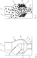
- FIG 1 shows an external perspective view of an exemplary dosing device for granular material according to an embodiment of the invention.
- the metering device comprises a housing 1, within which a conveyor device (not visible here) is rotatably mounted.
- the conveying device interacts with a housing wall or a guide element in such a way that granular material can be conveyed from a receiving area into a delivery area.
- An outlet opening is provided in the discharge area, through which the granular material can be discharged from the housing 1.
- the granular material discharged in this way can, for example, have a Figure 1 indicated connection line 2 are passed to a delivery device.
- the dispensing device can comprise, for example, a coulter.
- FIG. 1 a collection container 3 for granular material is shown.
- a return line 4 opens into the collecting container 3, which connects the collecting container 3 and the interior of the housing 1 to one another, so that grains of the granular material can be conveyed from the housing 1 into the collecting container 3 via the return line 4.
- Granular material for example seed
- This granular material, together with the granular material supplied via the return line 4, can form a seed supply or buffer within the collecting container 3.
- the granular material can then be introduced from the collecting container 3 via the side wall 6 of the housing 1 into the interior of the housing 1 via a feed device, which is not visible here, so that it is made available there for the conveying device.
- This invisible feed device is part of a pre-metering unit 7, which in Figure 1 is arranged below the collecting container 3.
- the collecting container 3 and the pre-metering unit 7 are connected here via a connecting line 8.
- the connecting line 8 connects to a funnel-shaped element 9, which is formed by a lower wall section of the collecting container 3.
- the connecting line 8 forms, as it were, a funnel neck to the funnel-shaped element 9.
- the funnel-shaped element 9 has an outlet opening (not visible here) which opens into the connecting line 8.
- a section 10 of the collecting container 3 Immediately above the funnel-shaped element 9 is a section 10 of the collecting container 3, in which a multiplicity of passage openings are provided, which form an air outlet grille or air outlet sieve. Through these air outlet openings or bores in section 10, it is possible to make the supply of granular material into the collecting container 3 at least partially self-regulating.
- a nursing system can be used to load the collecting container 3.
- the collecting container 3 can be connected to a central storage container via a pneumatic delivery channel.
- the delivery channel can be pressurized with an overpressure relative to the atmospheric pressure.
- there is an air flow via the pneumatic conveying channel and the air outlet openings in section 10 there is also a conveying of granular material, in particular seed, from the central storage container into the collecting container 3.
- the conveying air flow stops in the pneumatic conveying channel, so that the further supply of granular material from the central storage container via the opening 5 in the collecting container 3 stops.
- FIG 2 is a section through the exemplary metering device according to Figure 1 shown.
- the housing 1 in the interior of which the rotatably mounted conveyor 11 is shown schematically.
- Granular material can be discharged from the housing 1 via this outlet opening 12, in particular after it has been conveyed from the receiving device 11 into the feed area and thus metered.
- the conveying device 11 can serve in particular as a separating device, so that individual grains of the granular material are introduced into the connecting channel 2 via the outlet opening 12 at regular intervals.
- the axis of rotation of the conveyor 8 runs horizontally in this example. In operation of the metering device, the axis of rotation runs parallel to the agricultural soil to be worked.
- FIG. 2 parts of the pre-metering unit 7, which opens into the housing 1 via the side wall 6, can be seen. Shown is a rotor 13 designed as a screw conveyor, which is suitable for conveying granular material from the collecting container 3 into the interior of the housing 1.
- the axis of rotation of the rotor 13 is coaxial with the axis of rotation of the conveyor 11.
- the rotor 13 could also drive an internal thread which is arranged in the interior of the pre-metering unit 7.
- a motor or drive not shown, is provided to drive the conveyor 11.
- This motor or drive can also be used
- Driving the pre-metering unit 7, in particular the rotor 13, may be provided.
- the metering device can be designed such that the conveyor device rotates at a frequency between 5 Hz and 60 Hz.
- the conveying device By designing the conveying device with, for example, three centering slides, which are each designed for conveying a grain, a singulation frequency of 15 Hz to 180 Hz is made possible. As a result, very small distances between the deposited grains can be achieved.
- FIG. 2 The funnel-shaped element 9 and its outlet opening 14, which opens into the connecting line 8, can be seen.
- the outlet opening 14 is connected to the pre-metering unit 7 via the connecting line 8.
- the wall of the funnel-shaped element 9 widens conically from the outlet opening 14 to a feed opening 15.
- the mouth 16 of the return line 4 is arranged above the outlet opening 14.
- the mouth 16 of the return line 4 is arranged concentrically with the outlet opening 14. “Concentric” here means that the center or center of gravity of the mouth 16, when it is projected into the plane of the outlet opening 14, is equal to the center or center of gravity of the outlet opening 14.
- FIG 3 a cross section through an exemplary collecting container 3 is shown.
- the funnel-shaped element 9 with its outlet opening 14 and the inlet opening 15 surrounding the return line 4 in a ring.
- the mouth 16 of the return line 4 lying in one plane with the inlet opening 15 is arranged concentrically with the outlet opening 14.
- the center of the mouth 16, like the center of the outlet opening 14, thus lies on the longitudinal or symmetry axis of the funnel-shaped element 9.
- the connecting line 8 connects to the outlet opening 14 and forms a funnel neck to the funnel-shaped element 9.
- the return line 4 is partially arranged inside the collecting container 3.
- the line section 4 ' is arranged coaxially to the longitudinal or symmetry axis of the funnel-shaped element 9.
- the diameter of the mouth 16 is larger than the diameter of the outlet opening 14.
- Figure 4 shows the collection container 3 of the Figure 3 however with granular material incorporated therein.
- the conveyor 11 in the housing 1 of the metering device picks up granular material in a receiving area and then conveys it to the delivery area in such a way that a desired number of grains per unit time is dispensed via the outlet opening 12, usually a single grain. So that the separation can be carried out properly, a larger number of grains of the granular material must be provided in the receiving area of the conveyor.
- excess grains are separated out by interaction with the housing wall or a guide element. These separated grains can then be discharged from the housing 1 via the return line 4 and returned to the collecting container 3.
- These returned grains are introduced into the funnel-shaped element 9 due to the concentric arrangement of the mouth near the longitudinal or symmetry axis of the funnel-shaped element 9.
- Granular material which is introduced into the collecting container 3 via the inlet opening 5 via a refill system, only passes through the annular feed opening 15 of the funnel-shaped element 9 into an area with a greater distance from the longitudinal or symmetrical axis of the funnel-shaped element 9. As a result, these usually only reach in the area of the outlet opening 14 when the support effect via the central grains ceases. This in turn is usually the case when the return of the granular material via the return channel 4 is reduced or terminates.
- the conveying element of the pre-metering unit 7 can Figure 2 be designed such that it introduces ten grains of the granular material into the interior of the housing 1 with each revolution.
- one grain is removed from the ten grains supplied by the conveyor 11.
- the remaining nine grains are returned to the collecting container 3 via the return line 4.
- the returned nine grains initially slide into the pre-metering unit 7 via the outlet opening 14 and the connecting channel 8, while a grain slips out of the seed column of the storage container 3.
- 10 grains can be conveyed to the conveyor 11 again.
- FIG. 5 An alternative embodiment of an exemplary collecting container 3 is shown.
- This collecting container 3 has an inlet opening 5, through which, as described above, granular material can be introduced into the collecting container 3 from a refill system, not shown here.
- a return line likewise not shown here, opens into the collecting container 3 via the mouth 18.
- a discharge opening 17 is arranged at the bottom of the collecting container 3, via which the collecting container 3 is connected to a pre-metering unit 7.
- the pre-metering unit 7 can be designed and arranged as described above.
- the mouth 18 is arranged above the discharge opening 17 and overlaps it.
- the inlet opening 5 is arranged above an inclined plane 19, which partly forms the bottom of the collecting container 3.
- the collecting container 3 is also divided into two sub-chambers 21, 22 via a partition 20. Since the partition 20 does not extend to the bottom of the collecting container 3, a passage 23 is formed, through which granular material can reach the outlet opening 17 from the partial chamber 21.
- the arrangement of the openings shown can achieve that granular material introduced via the return line is preferred to granular material Material that is supplied via the inlet opening 5 can be brought out of the collecting container 3.
- the grain flow, which leads from the mouth 18 to the discharge opening 17, can block the slipping of granular material over the inclined plane 19. Only when this flow diminishes or stops, does granular material reach the outlet opening 17 via the inclined plane 19.
- FIG 6 A further alternative embodiment of an exemplary collecting container 3 is shown.
- This collecting container 3 also has an inlet opening 5, through which, as described above, granular material can be introduced into the collecting container 3 from a refill system, not shown here.
- a return line likewise not shown here, opens into the collecting container 3 via the mouth 18.
- a discharge opening 17 is here in contrast to the embodiment of FIG Figure 5 arranged in a side wall of the collecting container 3.
- Granular material can be brought into a pre-metering unit (not shown here) via the discharge opening 17.
- the collection container 3 comprises the Figure 6 two sub-chambers 21, 22 which are connected via a passage 23.
- the partition 20 is not a flat wall, but a curved one.
- the discharge opening 17 is arranged completely in the second partial chamber 22.
- a level P of granular material is formed during operation of the metering device, which level comes from the return line on the one hand and from the feed via the refill system on the other hand.
- the level P should neither be too high nor too low.
- the size of the level depends, among other things, on the flowability of the granular material, since the newly supplied granular material is fed via the inclined plane 19.
- the size of the passage 23 can be made adjustable by means of a closing slide 24 (adjusting slide).
- the closing slide 24 can be moved as indicated by the double arrow in FIG Figure 6 indicated in the vertical direction, so that the distance between the Bottom of the collecting container 3 and the lower edge of the closure slide 24 and thus the size of the passage 23 can be varied.
- a larger opening in the passage 23 can be selected than in the case of very good flowability (in the case of rape, for example).
- the slide valve 24 the flow behavior of different granular materials can be taken into account and the level P can be adjusted accordingly.
- an actuating element 25 as in FIG Figure 7A shown, used.
- This actuating element 25 is connected to the closing slide 24 and is guided out through an elongated hole 26 through the wall of the collecting container 3.
- the actuating element 25 can thus be operated from the outside, in particular can be moved continuously along the elongated hole 26.
- a fastening device, not shown in more detail, of the closure slide 24 can, for example, by force locking that the closure slide 24 remains in a set position.
- FIGS Figures 7B and 7C Two exemplary positions of the actuating element 25 are shown in FIGS Figures 7B and 7C shown.
- Figure 7B shows the lowest position of the actuating element 25 in the elongated hole 26. This position can correspond to a position of the closure slide 24, in which the size of the passage 23 becomes minimal. It is also possible that the closing slide 24 completely closes the passage 23 in this case.
- Figure 7C shows the uppermost position of the actuating element 25 in the elongated hole 26. This position can correspond to a position of the closure slide 24 in which the size of the passage 23 becomes maximum. It is also possible that the passage 23 is completely open in this case.
- FIG Figure 8 shows a further cross section of the embodiment of FIG Figure 6 . From this view it can be seen in particular that the closing slide 24 extends along the entire width of the passage 23 and the remaining size of the passage 23 is therefore determined by the distance between the lower edge of the closing slide 24 and the bottom of the collecting container 3.
- the locking slide 24 of this embodiment can be moved continuously. However, it is also conceivable to provide a locking slide which can only be locked in predetermined discrete positions.
- the predetermined discrete positions can correspond to different flow behavior and thus different granular materials.
- FIG 9 a perspective view of a further exemplary collecting container 3 is shown.
- the special feature of this exemplary embodiment lies in the fact that a non-return valve 27 is arranged in the collecting container in the region of the mouth 18 of the return line into the collecting container 3.
- the non-return valve 27 is arranged in particular between the mouth 18 and the discharge opening of the collecting container (not shown here).
- This check valve 27 serves to prevent or at least make it more difficult to convey granular material from the collecting container 3 via the return line into the housing of the metering device.
- the pivot axis 28 of the check valve 27 is in Figure 9 also hinted at.
- FIG 10A shows a cross section through the exemplary collecting container 3 of FIG Figure 9 .
- the check valve 27 is arranged in the open position in this case. In this position of the check valve 27, a transport of granular material in the transport direction indicated by the arrow A is possible. This transport direction A leads from the housing via the return line to the discharge opening 17.
- a stop 29 is provided in order to prevent the non-return flap 27 from contacting the inner wall of the collecting container 3. This ensures that there is a minimum engagement surface 30 for a flow opposite to direction A, so that the non-return flap 27 can be closed if the transport direction reverses for any reason.
- Figure 10B shows the check valve 27 in the blocking position, since there is a flow in direction B, which is opposite to the direction of transport A.
- a flow in direction B can occur, for example, if a nursing system is put into operation at the beginning of the processing, but no granular material has yet been arranged in the collecting container 3.
- the granular material supplied via the inlet opening 5 can be unhindered flow into the second chamber 22 and from there optionally further into the return line and the housing of the metering device. This is prevented by the check valve 27 in the locked position.
- a second stop 31 is provided in order to prevent the check valve 27 from pivoting beyond the blocking position in the opposite direction B.
- the first stop 29 and the second stop 31 are formed in one piece. Both stops are thus combined in an element which is rigidly connected to the check valve 27. However, it would also be conceivable that two separate stop elements are provided.
- Figure 11 shows a cross section through another exemplary collecting container 3.
- the guide elements 32, 33 are arranged on opposite inner sides of the collecting container 3, in particular the second partial chamber 22.
- the guide elements 32, 33 are wedge-shaped, the tips of the guide elements 32, 33 pointing in the direction of the desired transport direction A.
- the guide elements 32, 33 are arranged in a cascade manner, in particular the guide elements 33 are arranged offset with respect to the guide elements 32.
- Granular material which moves in the opposite direction B, tends to be guided through the guide elements 32, 33 to the side walls of the collecting container 3, where it is prevented from further movement in the opposite direction B by the guide elements 32, 33.
- the granular material becomes the passable center in the center of the Sub-chamber 22 directed so that transport to the discharge opening 17 is possible.
- two guide elements 32, 33 are provided on each side, but this is not restrictive. Fewer or more than two guide elements could also be provided per side.
- the Figures 12A and 12B each show a cross section through the housing of an exemplary metering device.
- a centering slide 34 can be seen here, which pushes granular material along a guide surface of a guide element 35 from a receiving area into a delivery area and thereby centers a grain by supporting or guiding it on both sides. Grains which are not centered and which are picked up in the receiving area and transported along the guide surface can consequently be rejected, so that the centered grain remains in the delivery area and can be passed on to a delivery element for placement on an agricultural area. In particular, exactly one grain can be guided centered by the centering slide.
- the metering device can thus be a separating device.
- a collecting space 37 extends into both sides of the guide element 35, into which separated grains reach. These separated grains can via a return line 4 (see for example Figure 1 ) get into a collection container.
- drivers 38 are provided in the collecting space 37 on both sides of the guide element 35.
- the drivers 38 are mounted on the centering slide 34, so that they can rotate together with the centering slide 34 about the common axis of rotation 36.
- Figure 12B shows a cross section through the housing of the exemplary dosing device of the Figure 12A , but in the delivery area of the conveyor.
- the guide element 35 has a changed shape in the delivery area.
- the guide element 35 has a ridge running in the direction of rotation.
- a separation of the granular material is further promoted by such a burr, since usually only one grain can be moved stably along the burr, namely the grain which is at least partially centered by the centering slide 34.
- the predetermined path along the The guide surface along which the centering slide 34 moves a grain centered runs along the ridge.
- the separated grains 39 are shown in the collecting space 37 and are pushed by the drivers 38 along the inner circumferential surface of the housing 1, which radially delimits the collecting space, until they are conveyed into the return line at the mouth of the return line into the housing of the metering device.
- FIG 13 shows a further cross section through a housing 1 of an exemplary metering device.
- the illustration is simplified in order to illustrate the functioning of the drivers.
- the return line 4, which opens into the housing 1, can be seen.
- the return line 4 leads tangentially into the housing 1, so that a tangential transition 40 is created.
- two rotatably mounted drivers 38 are shown.
- the direction of rotation is indicated by an arrow.
- Separated grains 39 of the granular material can be moved along the collecting space by the drivers 38 and finally conveyed into the return line 4. This is particularly advantageous if the rejected grains 39 have not received sufficient kinetic energy through the rejection themselves to leave the housing 1 via the return line 4.
- the catches 38 are made of a flexible material, for example rubber. This allows the drivers 38 to dodge the direction of rotation when they encounter a jamming grain.
- FIG 14 shows an alternative embodiment of the drivers 38.
- the drivers 38 are rigid.
- the drivers 38 comprise joints 42, the axes of which extend transversely to the direction of rotation. Therefore the outer part of the drivers 38 dodge the direction of rotation when a driver 38 hits a jamming grain 43.
- the drivers 38 are stretched because the centrifugal force counteracts pivoting about the axis of the joint.
- the funnel-shaped element can also be a separate element which is arranged in the interior of the collecting container.
Landscapes
- Life Sciences & Earth Sciences (AREA)
- Soil Sciences (AREA)
- Environmental Sciences (AREA)
- Filling Or Emptying Of Bunkers, Hoppers, And Tanks (AREA)
- Pretreatment Of Seeds And Plants (AREA)
- Sowing (AREA)
- Supply Of Fluid Materials To The Packaging Location (AREA)
Description
Die Erfindung betrifft eine Dosiervorrichtung für granulares Material, insbesondere für Saatgut.The invention relates to a metering device for granular material, in particular for seeds.
Derartige Vorrichtungen finden in landwirtschaftlichen Sämaschinen Anwendung, um Saatgut in definierten Mengen an Abgabeelemente weiterzuleiten und dann auf einer landwirtschaftlichen Fläche abzulegen. Für bestimmtes Saatgut, beispielsweise Mais, ist es wünschenswert, einzelne Körner in vorherbestimmten Abständen abzulegen. Um das Saatgut zu vereinzeln, verwenden bekannte Dosiereinrichtungen eine mit einer Druckdifferenz beaufschlagbare Vereinzelungstrommel oder Vereinzelungsscheibe. Die Vereinzelungstrommel oder Vereinzelungsscheibe umfasst in Perforationsreihen angeordnete Perforationen, an denen sich das Saatgut anlagern kann, wodurch es zu einer Vereinzelung kommt.Devices of this type are used in agricultural seed drills in order to forward seeds in defined quantities to delivery elements and then to deposit them on an agricultural area. For certain seeds, for example maize, it is desirable to deposit individual grains at predetermined intervals. In order to separate the seeds, known metering devices use a separating drum or separating disc to which a pressure difference can be applied. The separating drum or separating disc comprises perforations arranged in rows of perforations, on which the seed can accumulate, whereby there is a separation.
Diese Vereinzelungstechnik ist jedoch nicht zufriedenstellend für Getreide, wie etwa Weizen, Roggen, Gerste, Hafer oder Raps anwendbar. Eine speziell auf einen derartigen Einsatz gerichtete Dosiervorrichtung ist daher aus der
Um das granulare Material in die Dosiervorrichtung einzubringen, verwenden die bekannten Systeme üblicherweise einen Zentraldosierer in Verbindung mit einem Verteilerkopf. Vom Verteilerkopf ausgehend führt eine Verbindungsleitung zum Gehäuse der Dosiervorrichtung.In order to introduce the granular material into the metering device, the known systems usually use a central metering device in connection with a distributor head. Starting from the distributor head, a connecting line leads to the housing of the metering device.
Im Gehäuse stehen somit einerseits die zur erneuten Förderung in den ersten Gehäusebereich zurückgeführten Körner, als auch die über die Verbindungsleitung neu eingebrachten Körner für die Dosierung bereit. Eine wenigstens teilweise bedarfsgerechte Zuführung von granularem Material an die Dosiervorrichtung ist mit derartigen Systemen nicht möglich.The grains that are returned to the first housing area for renewed conveyance and the grains newly introduced via the connecting line are thus available in the housing for metering. Systems of this type are not capable of supplying granular material to the metering device at least partially as required.
Obwohl also beispielsweise zur erneuten Förderung in den ersten Gehäusebereich zurückgeführte Körner zur Verfügung stehen, wird weiteres granulares Material von außen zugeführt. Dies kann dazu führen, dass ein Körnerpuffer im ersten Gehäusebereich zu groß wird, was sich wiederum negativ auf die Dosierqualität, insbesondere auf die Vereinzelungsqualität, auswirken kann.So, for example, although grains returned to the first housing area are available for further conveying, further granular material is supplied from the outside. This can lead to a grain buffer in the first housing area becoming too large, which in turn can have a negative effect on the dosing quality, in particular on the separation quality.
Aufgabe der Erfindung ist es daher, eine Dosiervorrichtung für granulares Material, insbesondere Saatgut, bereitzustellen, welche eine verbesserte Dosierqualität, insbesondere Vereinzelungsqualität, ermöglicht.The object of the invention is therefore to provide a metering device for granular material, in particular seed, which enables improved metering quality, in particular separating quality.
Diese Aufgabe wird durch eine Vorrichtung gemäß Patentanspruch 1 gelöst. Weitere vorteilhafte Ausgestaltungen der Erfindung sind in den abhängigen Ansprüchen angegeben.This object is achieved by a device according to claim 1. Further advantageous embodiments of the invention are specified in the dependent claims.
Gemäß der Erfindung ist es also vorgesehen, dass das Gehäuse mit einem Sammelbehälter zum Bereitstellen von granularem Material verbunden ist und eine Rückleitung vom Gehäuse in den Sammelbehälter führt. Dadurch kann gewissermaßen ein Reservoir an granularem Material für die Fördereinrichtung im Sammelbehälter bereitgestellt werden, von wo aus es an die Fördereinrichtung geleitet werden kann. Da eine Rückleitung vom Gehäuse in den Sammelbehälter führt, können ausgesonderte Körner des granularen Materials aus dem Gehäuse der Fördereinrichtung ausgebracht und in den Sammelbehälter gefördert werden. Diese ausgesonderten Körner tragen also nicht zu einer unnötigen Vergrößerung des Puffers im Gehäuse bei, so dass die Dosierqualität, insbesondere die Vereinzelungsqualität, verbessert werden kann.According to the invention, it is therefore provided that the housing is connected to a collecting container for providing granular material and leads a return line from the housing into the collecting container. As a result, a reservoir of granular material can be provided for the conveyor in the collecting container, from where it can be directed to the conveyor. Since a return line leads from the housing into the collecting container, separated grains of the granular material can be discharged from the housing of the conveying device and conveyed into the collecting container. These separated grains therefore do not contribute to an unnecessary enlargement of the buffer in the housing, so that the dosing quality, in particular the separation quality, can be improved.
Bei dem granularen Material kann es sich insbesondere um Saatgut handeln, alternativ oder zusätzlich jedoch auch um granulares Düngemittel oder granulares Pestizid. Das Saatgut kann insbesondere Saatgut für Getreide, wie etwa Weizen, Roggen, Gerste, Hafer oder Raps, sein.The granular material can in particular be seed, but alternatively or additionally, it can also be granular fertilizer or granular Pesticide. The seeds can in particular be seeds for cereals, such as wheat, rye, barley, oats or rapeseed.
Die Rückleitung kann so vom Gehäuse in den Sammelbehälter führen, dass granulares Material vom Inneren des Gehäuses über die Rückleitung in den Sammelbehälter förderbar ist.The return line can lead from the housing into the collection container in such a way that granular material can be conveyed from the inside of the housing via the return line into the collection container.
Der Sammelbehälter ist über eine Einlassöffnung mit granularem Material befüllbar, insbesondere über ein Nachfüllsystem, etwa ein Nursingsystem.The collection container can be filled with granular material via an inlet opening, in particular via a refill system, such as a nursing system.
Der Sammelbehälter kann so ausgebildet sein, dass über die Rückleitung eingebrachtes granulares Material bevorzugt gegenüber granularem Material, das über die Einlassöffnung zugeführt wird, aus dem Sammelbehälter ausbringbar ist. Dadurch kann erreicht werden, dass zunächst die während der Dosierung ausgesonderten Körner des granularen Materials Verwendung finden. Die Zuführung von granularem Material über ein Nachfüllsystem kann dann bedarfsgerecht gesteuert oder geregelt werden.The collecting container can be designed in such a way that granular material introduced via the return line can be discharged from the collecting container, preferably over granular material which is supplied via the inlet opening. It can thereby be achieved that the grains of the granular material which are separated out during the dosing are first used. The supply of granular material via a refill system can then be controlled or regulated as required.
Der Sammelbehälter kann insbesondere eine Auslauf- oder Ausbringöffnung aufweisen, über die granulares Material aus dem Sammelbehälter ausbringbar ist, wobei eine Mündung der Rückleitung in den Sammelbehälter oberhalb der Auslauf- oder Ausbringöffnung angeordnet ist und diese vollständig oder teilweise überlappt. Dadurch kann eine Bevorzugung des über die Rückleitung eingebrachten Materials erreicht werden. Die Angabe "oberhalb" bezieht sich hier insbesondere auf die Position beim Betrieb der Dosiervorrichtung.The collecting container can in particular have an outlet or discharge opening, via which granular material can be discharged from the collecting container, an opening of the return line in the collecting container being arranged above the outlet or discharge opening and overlapping it completely or partially. In this way, preference can be given to the material introduced via the return line. The indication "above" refers here in particular to the position when the metering device is in operation.
Der Sammelbehälter kann ein trichterförmiges Element umfassen, wobei das trichterförmige Element eine Zufuhröffnung und eine Auslauföffnung umfasst, und wobei eine Mündung der Rückleitung in den Sammelbehälter konzentrisch zur Auslauföffnung des trichterförmigen Elements angeordnet ist. Die Auslauföffnung des trichterförmigen Elements kann der oben genannten Ausbringöffnung entsprechen oder mit dieser verbunden sein.The collecting container can comprise a funnel-shaped element, the funnel-shaped element comprising a feed opening and an outlet opening, and an opening of the return line in the collecting container being arranged concentrically to the outlet opening of the funnel-shaped element. The outlet opening of the funnel-shaped element can correspond to or be connected to the above-mentioned discharge opening.
Diese Ausführungsform nützt die Erkenntnis aus, dass granulares Material aus einem trichterförmigen Behälter zunächst aus einem zentralen Bereich entlang der Symmetrieachse ausläuft. Erst wenn die Stützwirkung durch die zentral auslaufenden Körner nachlässt, laufen Körner aus den Außenbereichen nach. Dadurch, dass eine Mündung der Rückleitung in den Sammelbehälter konzentrisch zu einer Auslauföffnung des trichterförmigen Elements angeordnet ist, ist es daher möglich, dass zunächst die aus dem Gehäuse stammenden Körner des granularen Materials über die Rückleitung und die Auslauföffnung wieder in das Gehäuse verbracht werden, und dort erneut für die Fördereinrichtung bereitstehen. Erst wenn der über die Rückleitung führende Strom von granularem Material nachlässt, folgen Körner aus dem im Sammelbehälter angeordneten Körnerpuffer.This embodiment takes advantage of the knowledge that granular material from a funnel-shaped container initially runs out of a central region along the axis of symmetry. Only when the support effect through the central grains that run out, grains run from the outside areas. Because a mouth of the return line in the collecting container is arranged concentrically to an outlet opening of the funnel-shaped element, it is therefore possible that the grains of the granular material originating from the housing are first brought back into the housing via the return line and the outlet opening, and be there again for the conveyor. Only when the flow of granular material via the return line subsides does grain follow from the grain buffer arranged in the collecting container.
Durch die genannten Maßnahmen ist es also möglich, granulares Material bedarfsgerecht der Fördereinrichtung zuzuführen. Dadurch kann die Qualität der Dosierung, insbesondere der Vereinzelung, erhöht werden.The measures mentioned make it possible to feed granular material to the conveyor as required. As a result, the quality of the dosage, in particular the singulation, can be increased.
Unter einem "trichterförmigen Element" kann hierin insbesondere ein Element verstanden werden, bei dem die Auslauföffnung über eine sich, insbesondere konisch, erweiternde Wandung mit der Zufuhröffnung verbunden ist. Das trichterförmige Element kann insbesondere so ausgebildet sein, dass die Zufuhröffnung größer ausgebildet ist als die Auslauföffnung, die Zuführöffnung insbesondere also einen größeren Durchmesser aufweist, als die Auslauföffnung.A “funnel-shaped element” can be understood here to mean, in particular, an element in which the outlet opening is connected to the feed opening via a, in particular conically, widening wall. The funnel-shaped element can in particular be designed in such a way that the feed opening is made larger than the outlet opening, the feed opening therefore in particular has a larger diameter than the outlet opening.
Das trichterförmige Element kann insbesondere in Bezug auf eine Längs- oder Symmetrieachse rotationssymmetrisch ausgebildet sein.The funnel-shaped element can be rotationally symmetrical, in particular with respect to a longitudinal or symmetry axis.
Unter der Angabe "konzentrisch" kann hierin insbesondere verstanden werden, dass der Mittelpunkt oder Schwerpunkt der Mündung der Rückleitung gleich dem Mittelpunkt oder Schwerpunkt der Auslauföffnung ist, wenn die Mündung und die Auslauföffnung in eine gemeinsame Ebene projiziert werden. Die gemeinsame Ebene kann insbesondere senkrecht zur Längs- oder Symmetrieachse des trichterförmigen Elementes liegen.The term “concentric” can be understood here in particular to mean that the center or center of gravity of the mouth of the return line is equal to the center or center of gravity of the outlet opening if the mouth and the outlet opening are projected into a common plane. The common plane can in particular be perpendicular to the longitudinal or symmetry axis of the funnel-shaped element.
Mit anderen Worten kann unter der Angabe "konzentrisch" verstanden werden, dass der Mittelpunkt oder Schwerpunkt der Mündung der Rückleitung und der Mittelpunkt oder Schwerpunkt der Auslauföffnung beide auf der Längs- oder Symmetrieachse des trichterförmigen Elementes liegen.In other words, the term “concentric” can be understood to mean that the center or center of gravity of the mouth of the return line and the center or center of gravity of the outlet opening are both on the longitudinal or symmetrical axis of the funnel-shaped element.
Die Mündung der Rückleitung kann in einer Ebene mit der Zufuhröffnung liegen. Die Mündung der Rückleitung kann im Betrieb der Dosiervorrichtung insbesondere oberhalb der Auslauföffnung angeordnet sein.The mouth of the return line can lie in one plane with the feed opening. The mouth of the return line can be arranged, in particular, above the outlet opening during operation of the metering device.
Die Mündung der Rückleitung kann insbesondere im Inneren des Sammelbehälters angeordnet sein. Insbesondere kann also die Rückleitung selbst teilweise im Inneren des Sammelbehälters angeordnet sein. Ein Abschnitt des Teils der Rückleitung, der im Sammelbehälter angeordnet ist, kann koaxial zur Längsachse oder Symmetrieachse des trichterförmigen Elements angeordnet sein.The mouth of the return line can be arranged in particular in the interior of the collecting container. In particular, the return line itself can thus be partially arranged inside the collecting container. A portion of the part of the return line which is arranged in the collecting container can be arranged coaxially to the longitudinal axis or axis of symmetry of the funnel-shaped element.
Das trichterförmige Element kann insbesondere durch einen Wandabschnitt des Sammelbehälters gebildet werden. Mit anderen Worten kann der Sammelbehälter selbst wenigstens abschnittsweise trichterförmig ausgebildet sein.The funnel-shaped element can in particular be formed by a wall section of the collecting container. In other words, the collecting container itself can be funnel-shaped at least in sections.
Der Sammelbehälter weist eine oben erwähnte Einlassöffnung auf, über die granulares Material in den Sammelbehälter eingebracht werden kann. Die Einlassöffnung kann im Betrieb insbesondere oberhalb der Zufuhröffnung und der Auslauföffnung des trichterförmigen Elements angeordnet sein. Dadurch kann granulares Material unter Schwerkraftwirkung über die Zuführöffnung in das trichterförmige Element gelangen.The collecting container has an inlet opening mentioned above, through which granular material can be introduced into the collecting container. In operation, the inlet opening can be arranged, in particular, above the feed opening and the outlet opening of the funnel-shaped element. This allows granular material to enter the funnel-shaped element via the feed opening under the action of gravity.
Die Zufuhröffnung kann ringförmig ausgebildet sein und insbesondere die Mündung der Rückleitung umgeben. Dadurch befinden sich die von außen zugeführten Körner bei einem größeren radialen Abstand im trichterförmigen Element, als die Körner, welche über die Rückleitung vom Gehäuse in das trichterförmige Element eingebracht werden. Die über die Rückleitung eingebrachten Körner können daher bevorzugt über die Auslauföffnung ausgebracht werden.The feed opening can be annular and in particular surround the mouth of the return line. As a result, the grains supplied from the outside are located at a greater radial distance in the funnel-shaped element than the grains which are introduced from the housing into the funnel-shaped element via the return line. The grains introduced via the return line can therefore preferably be discharged via the outlet opening.
Über die Einlassöffnung kann der Sammelbehälter mit einem Nachfüllsystem verbunden sein, insbesondere einem Nursingsystem. Das Nursingsystem kann einen zentralen Vorratsbehälter für granulares Material umfassen, wobei der zentrale Vorratsbehälter über einen pneumatischen Förderkanal mit der Einlassöffnung des Sammelbehälters verbunden ist. Das Nursingsystem kann außerdem ein Gebläse umfassen, mit dem ein Förderluftstrom im pneumatischen Förderkanal erzeugbar ist.The collecting container can be connected to a refill system, in particular a nursing system, via the inlet opening. The nursing system can comprise a central storage container for granular material, the central storage container being connected to the inlet opening of the collecting container via a pneumatic conveying channel. The nursing system can also include a blower with which a conveying air flow can be generated in the pneumatic conveying duct.
Alternativ kann die Einlassöffnung des Sammelbehälters auch mit einem Verteilerkopf verbunden sein.Alternatively, the inlet opening of the collecting container can also be connected to a distributor head.
Das granulare Material ist erfindungsgemäß über die Auslauf- oder Ausbringöffnung unmittelbar oder über eine Verbindungsleitung in eine Vordosiereinheit einbringbar, wobei die Vordosiereinheit so ausgebildet ist, dass sie granulares Material über eine Zuführöffnung in das Gehäuse fördert. Die Zuführöffnung kann insbesondere in einer Wandung des Gehäuses angeordnet sein.According to the invention, the granular material can be introduced into a pre-metering unit directly via the outlet or discharge opening or via a connecting line, the pre-metering unit being designed such that it conveys granular material into the housing via a supply opening. The feed opening can in particular be arranged in a wall of the housing.
Die an die Auslauföffnung optional anschließende Verbindungsleitung kann einen Trichterhals zum trichterförmigen Element bilden. Der Trichterhals kann zylindrisch, insbesondere kreiszylindrisch, ausgebildet sein. Es ist jedoch auch möglich, dass auch die Seitenwandung des Trichterhalses beispielsweise konisch ausgebildet ist.The connecting line optionally adjoining the outlet opening can form a funnel neck to the funnel-shaped element. The funnel neck can be cylindrical, in particular circular cylindrical. However, it is also possible for the side wall of the funnel neck to be conical, for example.
Die Vordosiereinheit umfasst erfindungsgemäß einen Rotor, dessen Drehachse koaxial zur Drehachse der Fördereinrichtung verläuft. Der Rotor kann mit Förderelementen verbunden sein, welche das granulare Material in das Gehäuse der Dosiervorrichtung fördern.According to the invention, the pre-metering unit comprises a rotor, the axis of rotation of which runs coaxially to the axis of rotation of the conveying device. The rotor can be connected to conveying elements which convey the granular material into the housing of the metering device.
Das granulare Material kann unter Schwerkraftwirkung vom Sammelbehälter in die Vordosiereinheit förderbar sein. Dafür kann die Auslauföffnung des trichterförmigen Elements im Betrieb insbesondere oberhalb der Vordosiereinheit angeordnet sein. Auf diese Weise ist eine besonders einfache Förderung des granularen Materials möglich.The granular material can be conveyed from the collecting container into the pre-metering unit under the action of gravity. For this purpose, the outlet opening of the funnel-shaped element can be arranged, in particular, above the pre-metering unit during operation. In this way, particularly simple conveyance of the granular material is possible.
Der Durchmesser der Mündung der Rückleitung kann größer als oder gleich groß wie der Durchmesser der Auslauföffnung sein. Dadurch kann in besonderem Maße erreicht werden, dass über die Rückleitung in den Sammelbehälter eingebrachtes Material bevorzugt über die Auslauföffnung ausgeschleust wird. Erst wenn die Rückführung von granularem Material über die Rückleitung verringert wird oder abbricht, wird granulares Material über die Auslauföffnung ausgebracht, welches über das Nachfüllsystem neu in den Sammelbehälter eingebracht wurde, sich zuvor also noch nicht im Gehäuse der Dosiervorrichtung befand.The diameter of the mouth of the return line can be greater than or equal to the diameter of the outlet opening. It can thereby be achieved to a particular degree that material introduced into the collecting container via the return line is preferably discharged via the outlet opening. Only when the return of granular material via the return line is reduced or stops, is granular material discharged through the outlet opening, which is then added to the collection container via the refill system was introduced, so it was not previously in the housing of the metering device.
Alternativ zur beschriebenen Ausführungsform, bei der der Sammelbehälter ein trichterförmiges Element umfasst, kann der Boden des Sammelbehälters eine zur Ausbringöffnung führende Ebene enthalten, welche in einer besonders vorteilhaften Ausführungsform als schiefe Ebene ausgebildet ist, wobei die Einlassöffnung oberhalb der Ebene angeordnet ist. Der Boden kann auch wenigstens teilweise in Form einer schiefen Ebene ausgebildet sein. Die Angabe "oberhalb" bezieht sich hier wiederum auf die Position beim Betrieb der Dosiervorrichtung.As an alternative to the described embodiment, in which the collecting container comprises a funnel-shaped element, the bottom of the collecting container can contain a plane leading to the discharge opening, which in a particularly advantageous embodiment is designed as an inclined plane, the inlet opening being arranged above the plane. The floor can also be at least partially in the form of an inclined plane. The indication "above" here again refers to the position when the metering device is in operation.
Durch diese Maßnahme gelangt das über ein Nachfüllsystem in den Sammelbehälter eingebrachte granulare Material zunächst auf die schiefe Ebene, von wo aus es zur Ausbringöffnung rutschen kann. Solange ein Körnerstrom über die Rückleitung in den Sammelbehälter und zur Ausbringöffnung führt, kann dieser Körnerstrom ein Nachrutschen von Körnern auf der schiefen Ebene verhindern oder verringern. Erst wenn dieser Körnerstrom nachlässt, können Körner von der schiefen Ebene in die Ausbringöffnung gelangen.As a result of this measure, the granular material introduced into the collecting container via a refill system first reaches the inclined plane, from where it can slide to the discharge opening. As long as a grain flow leads via the return line into the collecting container and to the discharge opening, this grain flow can prevent or reduce the sliding of grains on the inclined plane. Only when this grain flow subsides can grains get from the inclined plane into the discharge opening.
Der Winkel, mit dem die schiefe Ebene gegen die Horizontale geneigt ist, kann zwischen 10° und 45° betragen.The angle at which the inclined plane is inclined to the horizontal can be between 10 ° and 45 °.
Die schiefe Ebene kann insbesondere unmittelbar an die Ausbringöffnung angrenzen.The inclined plane can in particular directly adjoin the discharge opening.
Bei dieser Ausführungsform kann die Mündung der Rückleitung in den Sammelbehälter, wie oben ausgeführt, insbesondere oberhalb der Ausbringöffnung angeordnet sein und diese vollständig oder teilweise überlappen. Die Ausdehnung der Mündung der Rückleitung kann insbesondere größer sein als die Ausdehnung der Ausbringöffnung. Unter der "Ausdehnung" kann insbesondere die maximale oder mittlere Erstreckung der Mündung bzw. der Ausbringöffnung oder deren Durchmesser verstanden werden.In this embodiment, the mouth of the return line into the collecting container, as stated above, can be arranged in particular above the discharge opening and overlap it completely or partially. The extent of the mouth of the return line can in particular be greater than the extent of the discharge opening. The “extension” can be understood in particular to mean the maximum or average extension of the mouth or the discharge opening or its diameter.
Es ist auch denkbar, dass die Ausbringöffnung nicht am Boden des Sammelbehälters, sondern in einer Seitenwand des Sammelbehälters angeordnet ist. In diesem Fall überlappt die Mündung der Rückleitung nicht notwendigerweise die Ausbringöffnung.It is also conceivable that the discharge opening is not arranged on the bottom of the collecting container, but in a side wall of the collecting container is. In this case, the mouth of the return line does not necessarily overlap the discharge opening.
Der Sammelbehälter kann durch eine Trennwand in zwei Teilkammern unterteilt sein, wobei die Einlassöffnung in eine erste Teilkammer und die Mündung der Rückleitung in eine zweite Teilkammer mündet. Die erste und die zweite Teilkammer können über einen Durchlass verbunden sein. Der Durchlass kann insbesondere dadurch gebildet werden, dass die Trennwand vom Boden des Sammelbehälters beabstandet ist. Auch eine Durchlassöffnung in der Trennwand wäre aber denkbar.The collecting container can be divided into two subchambers by a partition, the inlet opening opening into a first subchamber and the mouth of the return line opening into a second subchamber. The first and the second partial chamber can be connected via a passage. The passage can in particular be formed in that the partition is spaced from the bottom of the collecting container. A passage opening in the partition would also be conceivable.
Die Trennwand kann dabei eine ebene Wandung sein, wobei die beiden Teilkammern an gegenüberliegenden Seiten der Trennwand angeordnet sind. Die Trennwand kann jedoch auch eine komplexere Geometrie aufweisen. Beispielsweise kann die Trennwand gekrümmt ausgebildet sein und/oder Teil der Außenwandung des Sammelbehälters sein. Beispielsweise kann die erste Teilkammer gewissermaßen eine Verlängerung der Förderleitung sein, die als Teil des Nachfüllsystems zur Einlassöffnung führt. Die zweite Teilkammer kann entsprechend eine Verlängerung der Rückleitung sein, die vom Gehäuse zur oben genannten Mündung der Rückleitung führt.The partition can be a flat wall, the two partial chambers being arranged on opposite sides of the partition. However, the partition can also have a more complex geometry. For example, the partition wall can be curved and / or be part of the outer wall of the collecting container. For example, the first partial chamber can be an extension of the delivery line, which leads to the inlet opening as part of the refill system. The second sub-chamber can accordingly be an extension of the return line, which leads from the housing to the mouth of the return line mentioned above.
Die Ausbringöffnung kann insbesondere in der zweiten Teilkammer angeordnet sein, insbesondere vollständig.The discharge opening can in particular be arranged in the second sub-chamber, in particular completely.
Die Zuführung von über die Einlassöffnung eingebrachtem granularem Material zur Ausbringöffnung kann mittels eines Verschlussschiebers (Stellschiebers) einstellbar sein.The supply of granular material introduced via the inlet opening to the discharge opening can be adjustable by means of a closing slide (adjusting slide).
Insbesondere kann die Größe des Durchlasses zwischen den beiden Teilkammern über einen Verschlussschieber einstellbar sein. Der Verschlussschieber kann insbesondere manuell betätigbar sein. Dafür kann ein Betätigungselement durch die Wandung des Sammelbehälters nach außen geführt sein, sodass das Betätigungselement von außen bedient werden kann. Insbesondere kann das Betätigungselement insbesondere starr mit dem Verschlussschieber gekoppelt sein, sodass eine Bewegung des Betätigungselements auf den Verschlussschieber übertragbar ist. In der Wandung des Sammelbehälters kann eine Durchgangsöffnung, insbesondere ein Langloch, vorgesehen sein, in der das Betätigungselement geführt bewegt werden kann.In particular, the size of the passage between the two subchambers can be adjustable via a slide valve. The locking slide can in particular be actuated manually. For this purpose, an actuating element can be guided outwards through the wall of the collecting container, so that the actuating element can be operated from the outside. In particular, the actuating element can in particular be rigidly coupled to the closing slide, so that a movement of the actuating element can be transmitted to the closing slide. Can in the wall of the collecting container a through opening, in particular an elongated hole, can be provided in which the actuating element can be moved in a guided manner.
Durch diese Einstellbarkeit kann der an der Ausbringöffnung anstehende Pegel granularen Materials beeinflusst oder gesteuert werden. Insbesondere kann dadurch der Fließfähigkeit des granularen Materials Rechnung getragen werden. Beispielsweise kann bei schlechter Fließfähigkeit (beispielsweise bei gebeizter Gerste) der Verschlussschieber weit geöffnet werden, gegebenenfalls vollständig, während bei sehr guter Fließfähigkeit (beispielsweise bei Raps) eine geringe Öffnung eingestellt wird. Dadurch wird verhindert, dass bei schlechter Fließfähigkeit ein zu niedriger Pegel vorliegt, was zu Fehlstellen führen könnte, bzw. dass bei guter Fließfähigkeit ein zu hoher Pegel vorliegt, der zu einer erhöhten Antriebsleistung für die Dosierung führen kann.This adjustability allows the level of granular material at the discharge opening to be influenced or controlled. In particular, the flowability of the granular material can be taken into account. For example, if the flowability is poor (for example in the case of pickled barley), the closure slide can be opened widely, if necessary completely, while if the flowability is very good (for example in the case of rapeseed) a small opening is set. This prevents the level from being too low in the case of poor flowability, which could lead to defects, or the level being too high when the flowability is good, which can lead to an increased drive power for the metering.
Die Position des Verschlussschiebers kann insbesondere kontinuierlich veränderbar sein. Dadurch kann auch die Größe des Durchlasses kontinuierlich eingestellt werden. Alternativ kann die Dosiervorrichtung so ausgebildet sein, dass die Position des Verschlussschiebers nur zwischen diskreten Positionen veränderbar ist. Die diskreten Positionen können unterschiedlichen Fließfähigkeiten und damit unterschiedlichen Arten granularen Materials entsprechen. Bei einer kontinuierlichen Einstellbarkeit können entsprechende Markierungen am Sammelbehälter vorgesehen sein, die auf die optimale Position des Verschlussschiebers für gegebene granulare Materialien hinweisen.The position of the closing slide can in particular be continuously changeable. This also allows the passage size to be continuously adjusted. Alternatively, the metering device can be designed such that the position of the closure slide can only be changed between discrete positions. The discrete positions can correspond to different flow capacities and thus different types of granular material. In the case of continuous adjustability, corresponding markings can be provided on the collecting container, which indicate the optimal position of the closure slide for given granular materials.
In einem Abschnitt der Wandung des Sammelbehälters kann wenigstens eine Luftauslassöffnung angeordnet sein. Insbesondere können eine Vielzahl von Luftauslassöffnungen in Form eines Luftauslassgitters oder eines Luftauslasssiebs angeordnet sein. Der Wandungsabschnitt des Sammelbehälters mit der wenigstens einen Luftauslassöffnung kann insbesondere oberhalb des trichterförmigen Elements angeordnet sein, insbesondere unmittelbar oberhalb an das trichterförmige Element angrenzen. Der Wandungsabschnitt des Sammelbehälters mit der wenigstens einen Luftauslassöffnung kann auch in einer Seitenwand des Sammelbehälters angeordnet sein, die oberhalb der schiefen Ebene angeordnet ist, insbesondere in einer Seitenwand der ersten Teilkammer.At least one air outlet opening can be arranged in a section of the wall of the collecting container. In particular, a plurality of air outlet openings can be arranged in the form of an air outlet grille or an air outlet sieve. The wall section of the collecting container with the at least one air outlet opening can be arranged in particular above the funnel-shaped element, in particular adjoining the funnel-shaped element directly above. The wall section of the collecting container with the at least one air outlet opening can also be arranged in a side wall of the collecting container which is arranged above the inclined plane, in particular in a side wall of the first partial chamber.
Über die wenigstens eine Luftauslassöffnung kann der Förderluftstrom zur Förderung von granularem Material in den Sammelbehälter beeinflusst werden. Insbesondere kann die wenigstens eine Luftauslassöffnung durch granulares Material im Sammelbehälter blockiert werden. In diesem Fall kann der Förderluftstrom derart abgeschwächt werden, dass es zu keiner Nachförderung von granularem Material zum Sammelbehälter mehr kommt. Die wenigsten eine Luftauslassöffnung kann insbesondere vorteilhaft mit einem Nursingsystem zusammenwirken. Dadurch ist insbesondere eine selbstregulierende Nachlieferung von granularem Material zum Sammelbehälter möglich.The conveying air flow for conveying granular material into the collecting container can be influenced via the at least one air outlet opening. In particular, the at least one air outlet opening can be blocked by granular material in the collecting container. In this case, the conveying air flow can be weakened in such a way that there is no further conveyance of granular material to the collecting container. At least one air outlet opening can cooperate particularly advantageously with a nursing system. This enables a self-regulating subsequent delivery of granular material to the collection container.
In der Rückleitung und/oder im Sammelbehälter können ein oder mehrere Elemente vorgesehen sein, welche einen Transport von granularem Material vom Sammelbehälter über die Rückleitung in das Gehäuse verhindern oder erschweren. Dadurch kann verhindert werden, dass ungewollt granulares Material über die Rückleitung in das Gehäuse der Dosiervorrichtung eingebracht wird. Zu einem solchen ungewollten Transport über die Rückleitung kann es beispielsweise unmittelbar nach dem Einschalten des Nachfüllsystems kommen, da in diesem Fall noch kein Saatgut im Sammelbehälter vorhanden ist, welche den vom Nachfüllsystem (insbesondere Nursingsystem) stammenden Körnerstrom bremsen würde.One or more elements can be provided in the return line and / or in the collection container, which elements prevent or complicate the transport of granular material from the collection container via the return line into the housing. This can prevent undesired granular material from being introduced into the housing of the metering device via the return line. Such an unwanted transport via the return line can occur, for example, immediately after the refill system is switched on, since in this case there is still no seed in the collecting container which would slow down the grain flow originating from the refill system (in particular the nursing system).
Die ein oder mehreren Elemente können insbesondere eine Rückschlagklappe umfassen. Mit anderen Worten kann in der Rückleitung und/oder im Sammelbehälter eine Rückschlagklappe angeordnet sein. Diese Rückschlagklappe kann so ausgebildet sein, dass sie einen Transport von granularem Material in einer Richtung (vom Gehäuse über die Rückleitung in den Sammelbehälter) erlaubt, während ein Transport in die Gegenrichtung (vom Sammelbehälter über die Rückleitung in das Gehäuse) blockiert wird.The one or more elements can in particular comprise a non-return valve. In other words, a non-return valve can be arranged in the return line and / or in the collecting container. This non-return valve can be designed in such a way that it allows transport of granular material in one direction (from the housing via the return line into the collecting container), while blocking transport in the opposite direction (from the collecting container via the return line into the housing).
Die Rückschlagklappe kann zwischen einer Durchlassstellung und einer Sperrstellung beweglich sein, insbesondere um eine Schwenkachse schwenkbar. In der Durchlassstellung wird ein Transport von granularem Material vom Gehäuse über die Rückleitung in den Sammelbehälter und weiter zur Ausbringöffnung ermöglicht. Durch ein erstes Anschlagelement, welches mit der Rückschlagklappe verbunden ist, kann verhindert werden, dass die Rückschlagklappe in der Durchlassstellung an einer Innenwandung der Rückleitung bzw. des Sammelbehälters anliegt. Dadurch bietet die Rückschlagklappe auch in Durchlassstellung eine Angriffsfläche für eine Strömung in Gegenrichtung.The check valve can be movable between a passage position and a blocking position, in particular pivotable about a pivot axis. In the open position, a transport of granular material from the housing via the return line into the collecting container and on to the discharge opening is made possible. A first stop element, which is connected to the check valve, can prevent the check valve in the Pass position bears against an inner wall of the return line or the collecting container. As a result, the non-return valve also offers an area of attack for a flow in the opposite direction in the open position.
Ein zweites Anschlagelement, welches mit der Rückschlagklappe verbunden ist, kann eine weitere Schwenkbewegung der Klappe in Gegenrichtung verhindern und die Rückschlagklappe so in der Sperrstellung fixieren.A second stop element, which is connected to the non-return valve, can prevent a further pivoting movement of the valve in the opposite direction and thus fix the non-return valve in the locked position.
Das erste und zweite Anschlagelement können einstückig ausgebildet sein. Es ist aber auch möglich, dass zwei separate Anschlagelemente vorgesehen sind.The first and second stop element can be formed in one piece. However, it is also possible for two separate stop elements to be provided.
Die Rückschlagklappe kann mehrteilig ausgebildet sein, beispielsweise als zweiteilige Flügelklappe.The non-return flap can be designed in several parts, for example as a two-part wing flap.
Wenn weder in der einen Richtung noch in der Gegenrichtung eine Strömung ausgebildet ist, kann die Rückschlagklappe auch in einer Neutralstellung angeordnet sein, die zwischen der Durchlassstellung und der Sperrstellung liegt, und bei der insbesondere keines der Anschlagelemente an einer Innenwandung des Rückkanals oder des Sammelbehälters anliegt.If there is no flow in either direction or in the opposite direction, the non-return flap can also be arranged in a neutral position, which lies between the open position and the blocking position, and in particular in which none of the stop elements bears against an inner wall of the return channel or the collecting container .
Die ein oder mehreren Elemente können alternativ oder zusätzlich keilförmige Leitelemente umfassen, deren Spitze in die gewünschte Transportrichtung weisen, die vom Gehäuse über die Rückleitung in den Sammelbehälter, und insbesondere weiter zur Ausbringöffnung, führt. Die Leitelemente können insbesondere kaskadenförmig angeordnet sein. Mit anderen Worten können an gegenüberliegenden Seiten der Rückleitung und/oder des Sammelbehälters jeweils mehrere Leitelemente in der gewünschten Transportrichtung hintereinander angeordnet sein. Insbesondere können die Leitelemente der gegenüberliegenden Seiten versetzt zueinander angeordnet sein.The one or more elements can alternatively or additionally comprise wedge-shaped guide elements, the tips of which point in the desired transport direction, which leads from the housing via the return line into the collecting container, and in particular further to the discharge opening. The guide elements can in particular be arranged in a cascade. In other words, a plurality of guide elements can be arranged one behind the other in the desired transport direction on opposite sides of the return line and / or the collecting container. In particular, the guide elements of the opposite sides can be arranged offset to one another.
Die Fördereinrichtung kann mit der Gehäusewandung oder dem Führungselement insbesondere so zusammenwirken, dass die Anzahl der geförderten Körner des granularen Materials vom Aufnahmebereich zum Abgabebereich hin abnimmt. Die Dosiervorrichtung kann insbesondere eine Vereinzelungsvorrichtung sein.The conveying device can interact with the housing wall or the guide element in particular in such a way that the number of conveyed grains of the granular material decreases from the receiving area to the delivery area. The metering device can in particular be a separating device.
Die Dosiervorrichtung, insbesondere die Fördereinrichtung, kann einen Zentrierschieber umfassen, der granulares Material entlang einer Führungsfläche eines Führungselements vom Aufnahmebereich in den Abgabebereich schiebt und dabei ein Korn zentriert, indem er es beidseitig abstützt oder führt. Nicht zentrierte Körner, die im Aufnahmebereich aufgenommen und entlang der Führungsfläche transportiert werden, können infolge ausgesondert werden, sodass im Abgabebereich das zentrierte Korn verbleibt und an ein Abgabeelement zur Ablage auf einer landwirtschaftlichen Fläche weitergeleitet werden kann. Insbesondere kann genau ein Korn durch den Zentrierschieber zentriert geführt werden. Die Dosiervorrichtung kann also eine Vereinzelungsvorrichtung sein.The metering device, in particular the conveying device, can comprise a centering slide which pushes granular material along a guide surface of a guide element from the receiving area into the delivery area and thereby centers a grain by supporting or guiding it on both sides. Grains which are not centered and which are picked up in the receiving area and transported along the guide surface can consequently be rejected, so that the centered grain remains in the delivery area and can be passed on to a delivery element for placement on an agricultural area. In particular, exactly one grain can be guided centered by the centering slide. The metering device can thus be a separating device.
Ausgesonderte Körner können über die Rückleitung in den Sammelbehälter gefördert werden.Separated grains can be conveyed into the collection container via the return line.
Die Angabe "beidseitig abstützt oder führt" bedeutet, dass der Zentrierschieber Elemente umfasst, welche das zentrierte Korn an beiden Seiten (auf die Drehrichtung des Zentrierschiebers bezogen) abstützen oder führen. Damit kann eine Bewegung des Korns quer zur Drehrichtung reduziert oder vermieden werden, sodass das zentrierte Korn im Wesentlichen entlang einer vorbestimmten Bewegungsbahn vom Aufnahmebereich in den Abgabebereich geschoben wird. Um das Korn seitlich zu führen ist es nicht erforderlich, dass der Zentrierschieber stets in direktem Kontakt mit dem Korn steht. Es ist ausreichend, wenn der Zentrierschieber verhindert, dass das Korn einen vorherbestimmten seitlich begrenzten Bereich verlässt.The indication "supported or guiding on both sides" means that the centering slide comprises elements which support or guide the centered grain on both sides (based on the direction of rotation of the centering slide). A movement of the grain transverse to the direction of rotation can thus be reduced or avoided, so that the centered grain is pushed essentially along a predetermined movement path from the receiving area into the delivery area. In order to guide the grain laterally, it is not necessary that the centering slide is always in direct contact with the grain. It is sufficient if the centering slide prevents the grain from leaving a predetermined, laterally limited area.
Als Drehrichtung wird die Bewegungsrichtung bezeichnet, in der sich der Zentrierschieber im Betrieb der Dosiervorrichtung bewegt. Mit anderen Worten bezeichnet die Drehrichtung die Richtung der Vorwärtsbewegung des Zentrierschiebers. Wenn sich der Zentrierschieber entlang einer Kreisbahn bewegt, ist die Bewegungsrichtung an jedem Punkt der Kreisbahn tangential zu dieser. Die Angaben "seitlich" oder "beidseitig" beziehen sich daher auf die Bereiche quer zur Drehrichtung.The direction of rotation is the direction of movement in which the centering slide moves during operation of the metering device. In other words, the direction of rotation denotes the direction of the forward movement of the centering slide. If the centering slide moves along a circular path, the direction of movement is tangential to the circular path at every point. The information "on the side" or "on both sides" therefore refers to the areas transverse to the direction of rotation.
Die Angabe "wenigstens teilweise" bedeutet in diesem Zusammenhang, dass der Zentrierschieber das Korn nicht durchgehend vom Aufnahmebereich bis zum Abgabebereich beidseitig abstützen oder führen muss. Beispielsweise kann es Zeit in Anspruch nehmen, bis sich das Korn so relativ zum Zentrierschieber ausgerichtet hat, dass eine beidseitige Abstützung oder Führung möglich ist. Während dieser Zeit kann das Korn bereits einen gewissen Weg vom Aufnahmebereich zum Abgabebereich bewegt werden. Das Korn kann aber auch entlang des gesamten Wegs beidseitig abgestützt oder geführt werden.In this context, the indication "at least partially" means that the centering slide does not continuously pass the grain from the receiving area to Support or guide the dispensing area on both sides. For example, it can take time until the grain has aligned itself relative to the centering slide so that it can be supported or guided on both sides. During this time, the grain can already be moved a certain distance from the receiving area to the delivery area. The grain can also be supported or guided on both sides along the entire path.
Der Zentrierschieber kann auch ein oder mehrere Elemente umfassen, welche das zentrierte Korn in Drehrichtung gesehen nach hinten abstützen. Die Elemente, welche die seitliche Abstützung oder Führung bewirken können zugleich auch die Abstützung nach hinten gewährleisten.The centering slide can also comprise one or more elements which support the centered grain in the direction of rotation to the rear. The elements that provide lateral support or guidance can also provide rear support.
Der Zentrierschieber kann so drehbar in dem Gehäuse gelagert sein, dass er entlang einer Kreisbahn bewegbar ist, wobei das Führungselement wenigstens teilweise entlang der Kreisbahn verläuft, und wobei die Breite der Führungsfläche vom Aufnahmebereich zum Abgabebereich hin abnimmt.The centering slide can be rotatably mounted in the housing such that it can be moved along a circular path, the guide element running at least partially along the circular path, and the width of the guide surface decreasing from the receiving area to the delivery area.
Durch die abnehmende Breite der Führungsfläche können die Körner, welche nicht durch den Zentrierschieber zentriert werden, im Laufe der Bewegung vom Aufnahmebereich in den Abgabebereich aufgrund der wegfallenden Stütze durch die Führungsfläche unter Zentrifugalkrafteinflüssen und/oder Schwerkrafteinflüssen ausgesondert werden. Auch die Breite des Führungselements insgesamt kann vom Aufnahmebereich zum Abgabebereich hin abnehmen.Due to the decreasing width of the guide surface, the grains, which are not centered by the centering slide, can be separated out during the movement from the receiving region into the delivery region due to the loss of support by the guide surface under the influence of centrifugal force and / or gravity. The overall width of the guide element can also decrease from the receiving area to the delivery area.
Der Zentrierschieber kann so im Gehäuse gelagert sein, dass die Kreisbahn im Betrieb der Dosiervorrichtung im Wesentlichen vertikal verläuft. Mit anderen Worten kann die Drehachse, um die der Zentrierschieber rotiert, horizontal verlaufen, insbesondere im Betrieb parallel zum zu bearbeitenden Boden. Insbesondere kann die Drehachse mit der Horizontalen einen Winkel zwischen 0° und 10°, insbesondere zwischen 0° und 5°, einschließen.The centering slide can be mounted in the housing such that the circular path runs essentially vertically when the metering device is in operation. In other words, the axis of rotation about which the centering slide rotates can run horizontally, in particular parallel to the ground to be worked during operation. In particular, the axis of rotation with the horizontal can form an angle between 0 ° and 10 °, in particular between 0 ° and 5 °.
Das Führungselement kann insbesondere radial außerhalb der Kreisbahn verlaufen. Mit anderen Worten kann das Führungselement die Kreisbahn wenigstens teilweise radial umgeben oder begrenzen. Das Führungselement kann insbesondere annähernd tangential entlang bestimmten Abschnitten der Kreisbahn verlaufen, insbesondere im Abschnitt der Kreisbahn zwischen dem Aufnahmebereich und dem Abgabebereich.The guide element can in particular run radially outside the circular path. In other words, the guide element can at least partially radially surround or delimit the circular path. The guide element can in particular approximately tangentially along certain sections of the Circular path, in particular in the section of the circular path between the receiving area and the delivery area.
Die Kreisbahn kann insbesondere durch ein äußerstes Ende oder eine Spitze des Zentrierschiebers überstrichen werden. Mit anderen Worten kann die Kreisbahn einen Radius aufweisen, der der Länge des Zentrierschiebers entspricht. Die Länge des Zentrierschiebers kann der maximalen radialen Erstreckung des Zentrierschiebers ausgehend von der Drehachse entsprechen.The circular path can be covered in particular by an extreme end or a tip of the centering slide. In other words, the circular path can have a radius which corresponds to the length of the centering slide. The length of the centering slide can correspond to the maximum radial extent of the centering slide starting from the axis of rotation.
Der Aufnahmebereich kann ein bestimmtes Kreissegment der Kreisbahn des Zentrierschiebers umfassen.The receiving area can comprise a specific circular segment of the circular path of the centering slide.
Im Abgabebereich kann die Stützwirkung des Führungselementes entfallen oder der Verlauf des Führungselementes sich derart ändern, dass das wenigstens eine Korn durch Fliehkraft in die Auslassöffnung gefördert wird.In the delivery area, the support effect of the guide element can be omitted or the course of the guide element can change such that the at least one grain is conveyed into the outlet opening by centrifugal force.
Als Führungsfläche des Führungselements wird hierin die für die Förderung des granularen Materials vom Aufnahmebereich in den Abgabebereich wirksame Fläche des Führungselements bezeichnet. Mit anderen Worten entspricht die Führungsfläche des Führungselements der Oberfläche des Führungselements, auf der Körner des granularen Materials bei der Förderung von dem Aufnahmebereich in den Abgabebereich hin bewegt werden. Aufgrund der Bewegung entlang der Kreisbahn wird das granulare Material durch Fliehkraft gegen die Führungsfläche des Führungselements gedrückt. Die Führungsfläche des Führungselements dient daher als Stütze für das granulare Material entgegen der Fliehkraft. Alternativ oder zusätzlich können die Körner auch durch die Schwerkraft gegen die Führungsfläche gedrückt werden. Dies kann insbesondere dann der Fall sein, wenn sich der Zentrierschieber gemäß einer Alternative nicht entlang einer Kreisbahn um die Drehachse bewegt, sondern entlang einer Bahn, die wenigstens teilweise parallel zur Horizontalen verläuft.The guide surface of the guide element refers here to the surface of the guide element which is effective for conveying the granular material from the receiving region into the discharge region. In other words, the guide surface of the guide element corresponds to the surface of the guide element on which grains of the granular material are moved during the conveyance from the receiving area into the delivery area. Due to the movement along the circular path, the granular material is pressed against the guide surface of the guide element by centrifugal force. The guide surface of the guide element therefore serves as a support for the granular material against the centrifugal force. Alternatively or additionally, the grains can also be pressed against the guide surface by gravity. This can be the case in particular if, according to an alternative, the centering slide does not move along a circular path around the axis of rotation, but rather along a path that is at least partially parallel to the horizontal.
Wenn die Breite der Führungsfläche abnimmt geht diese Stützwirkung, wie oben erwähnt, für bestimmte Körner des granularen Materials verloren, weshalb diese nicht weiter zum Abgabebereich hin gefördert werden können, sondern ausgesondert werden.As mentioned above, if the width of the guide surface decreases, this support effect is lost for certain grains of the granular material, which is why they cannot be conveyed further to the delivery area, but rather are separated out.
Die Breite der Führungsfläche kann vom Aufnahmebereich zum Abgabebereich hin kontinuierlich abnehmen. Dadurch können überschüssige Körner sukzessive ausgesondert werden. Die Breite der Führungsfläche kann jedoch auch diskontinuierlich abnehmen.The width of the guide surface can decrease continuously from the receiving area to the delivery area. In this way, excess grains can be separated out successively. However, the width of the guide surface can also decrease discontinuously.
Als Breite der Führungsfläche kann insbesondere die Ausdehnung der Führungsfläche quer zur Kreisbahn bezeichnet werden. Die Richtung quer zur Kreisbahn bezeichnet hierin eine Richtung, die an jedem Punkt der Kreisbahn senkrecht zur Tangente und senkrecht zum Radius der Kreisbahn verläuft. Die Ausdehnung der Führungsfläche in dieser Richtung wird entlang der, gegebenenfalls konturierten, Führungsfläche bestimmt.The width of the guide surface can in particular be the extension of the guide surface transverse to the circular path. The direction transverse to the circular path denotes here a direction which is perpendicular to the tangent and perpendicular to the radius of the circular path at each point of the circular path. The extent of the guide surface in this direction is determined along the optionally contoured guide surface.
Das Führungselement kann eine Vertiefung aufweisen, in die der Zentrierschieber wenigstens teilweise eingreift, wobei die Tiefe der Vertiefung entlang der Kreisbahn des Vereinzelungsschiebers vom Aufnahmebereich zum Abgabebereich hin abnimmt. Durch die Vertiefung im Aufnahmebereich ist es möglich, dass zuverlässig Saatgut durch den Zentrierschieber aufgenommen und entlang der Führungsfläche bewegt werden kann. Durch die abnehmende Tiefe der Vertiefung entlang der Kreisbahn kann wiederum eine Aussonderung überschüssiger Körner des granularen Materials bewirkt werden. Die Abnahme der Tiefe geht mit einer Abnahme der Breite der Führungsfläche einher.The guide element can have a depression into which the centering slide engages at least partially, the depth of the depression decreasing along the circular path of the separating slide from the receiving area to the delivery area. The recess in the receiving area makes it possible for seed to be reliably picked up by the centering slide and moved along the guide surface. Due to the decreasing depth of the depression along the circular path, excess grains of the granular material can in turn be separated. The decrease in depth is accompanied by a decrease in the width of the guide surface.
Die Vertiefung im Führungselement kann insbesondere einer Nut oder Kerbe entsprechen. Die Nut oder Kerbe kann insbesondere V-förmig ausgebildet sein.The depression in the guide element can in particular correspond to a groove or notch. The groove or notch can in particular be V-shaped.
Das Führungselement kann im Abgabebereich einen in Drehrichtung verlaufenden Grat aufweisen. Durch einen solchen Grat wird eine Vereinzelung des granularen Materials weiter gefördert, da entlang des Grats üblicherweise nur ein Korn stabil bewegt werden kann, nämlich das Korn, welches wenigstens teilweise durch den Zentrierschieber zentriert wird. Die vorherbestimmte Bahn entlang der Führungsfläche, entlang der der Zentrierschieber ein Korn zentriert bewegt, kann insbesondere entlang des Grats verlaufen.The guide element can have a ridge running in the direction of rotation in the delivery area. Such a burr further promotes separation of the granular material, since usually only one grain can be moved stably along the burr, namely the grain which is at least partially centered by the centering slide. The predetermined path along the guide surface, along which the centering slide moves a grain centered, can in particular run along the ridge.
Beidseitig des Führungselements kann ein Sammelraum für im Laufe des Transports vom Aufnahmebereich zum Abgabebereich ausgesonderte Körner des granularen Materials angeordnet sein, der mit dem Aufnahmebereich verbunden ist. Dadurch können ausgesonderte Körner wieder für den erneuten Transport vom Aufnahmebereich in den Abgabebereich bereitgestellt werden. Der Sammelraum kann durch die Wandung des Gehäuses begrenzt werden. Der Sammelraum kann gegenüber der Führungsfläche des Führungselements radial nach außen versetzt sein. Die ausgesonderten Körner können sich im Sammelraum also auf Kreisbahnen mit größerem Radius bewegen, als das oder die Körner, die durch den Zentrierschieber entlang der Führungsfläche geschoben werden.On both sides of the guide element, a collecting space for grains of the granular material that are separated during the transport from the receiving area to the delivery area can be arranged, which is connected to the receiving area is. In this way, separated grains can be made available for the renewed transport from the receiving area to the delivery area. The collection space can be limited by the wall of the housing. The collecting space can be offset radially outwards relative to the guide surface of the guide element. The separated grains can thus move in circular paths on circular orbits with a larger radius than the one or more grains that are pushed along the guide surface by the centering slide.
Insbesondere können ausgesonderte Körner des granularen Materials aber über die Rückleitung vom Sammelraum in den Sammelbehälter verbracht werden. Von dort aus können sie dann über eine Vordosiereinheit wieder in das Gehäuse eingebracht werden, und für den erneuten Transport vom Aufnahmebereich in den Abgabebereich bereitstehen. Dafür kann in der Wandung des Gehäuses eine Öffnung vorgesehen sein, über welche die Rückleitung in den Sammelraum mündet. Die Rückleitung kann insbesondere tangential in das Gehäuse einmünden.In particular, separated grains of the granular material can, however, be brought via the return line from the collecting space into the collecting container. From there, they can then be reintroduced into the housing by means of a pre-metering unit and be ready for the new transport from the receiving area to the delivery area. For this purpose, an opening can be provided in the wall of the housing, through which the return line opens into the collecting space. The return line can in particular open tangentially into the housing.
Die ausgesonderten Körner können daher unter der Wirkung der Fliehkraft und aufgrund ihrer kinetischen Energie, welche sie durch Wechselwirkung mit dem Zentrierschieber erhalten haben, in die Rückleitung gelangen. Es ist jedoch denkbar, dass diese kinetische Energie der Körner nicht ausreicht, um sie über die Rückleitung in den Sammelbehälter zu bewegen, beispielsweise bei geringen Drehzahlen des Zentrierschiebers oder wenn ein Korn frühzeitig in der Bewegung vom Aufnahmebereich in den Abgabebereich ausgesondert wird.The separated grains can therefore get into the return line under the effect of centrifugal force and due to their kinetic energy, which they have obtained through interaction with the centering slide. However, it is conceivable that this kinetic energy of the grains is not sufficient to move them via the return line into the collecting container, for example at low rotational speeds of the centering slide or if a grain is removed early in the movement from the receiving area into the delivery area.
Die Dosiervorrichtung kann daher wenigstens einen drehbar gelagerten Mitnehmer umfassen, durch welchen ausgesonderte Körner des granularen Materials im Sammelraum beschleunigt und in Folge durch Fliehkraft aus dem Sammelraum ausgebracht und in die Rückleitung gefördert werden können.The metering device can therefore comprise at least one rotatably mounted driver, by means of which separated grains of the granular material in the collecting space can be accelerated and subsequently brought out of the collecting space by centrifugal force and conveyed into the return line.
Insbesondere kann der wenigstens eine Mitnehmer so ausgebildet und angeordnet sein, dass er ein Korn des granularen Materials im Sammelraum in eine Rotationsbewegung um die Drehachse der Fördereinrichtung versetzen oder eine solche Rotationsbewegung verstärken kann.In particular, the at least one driver can be designed and arranged such that it can set a grain of the granular material in the collecting space into a rotational movement about the axis of rotation of the conveying device or can amplify such a rotational movement.
Die Dosiervorrichtung kann insbesondere zwei solche drehbar gelagerten Mitnehmer umfassen, die jeweils auf einer Seite des Führungselements angeordnet sind. Auch mehr als zwei Mitnehmer sind möglich.The metering device can in particular comprise two such rotatably mounted drivers, which are each arranged on one side of the guide element. More than two drivers are also possible.
Der wenigstens eine Mitnehmer kann, insbesondere starr, mit der Fördereinrichtung, insbesondere einem Zentrierschieber der Fördereinrichtung, verbunden sein. Der wenigstens eine Mitnehmer kann entsprechend um die Drehachse des Zentrierschiebers drehbar sein. Damit kann der wenigstens eine Mitnehmer auch durch den Antrieb der Fördereinrichtung angetrieben werden.The at least one driver can, in particular rigidly, be connected to the conveying device, in particular a centering slide of the conveying device. The at least one driver can accordingly be rotatable about the axis of rotation of the centering slide. The at least one driver can thus also be driven by the drive of the conveyor device.
Der wenigstens eine Mitnehmer kann so ausgebildet sein, dass er wenigstens teilweise entgegen der Drehrichtung ausweichen kann. Mit anderen Worten kann er also wenigstens teilweise entgegen seiner Bewegungsrichtung auslenkbar sein. Dadurch kann verhindert werden, dass Körner des granularen Materials an Scherstellen beschädigt werden. Eine solche Scherstelle kann beispielsweise an der Kante der Mündungsöffnung der Rückleitung ins Gehäuse entstehen. Der wenigstens eine Mitnehmer kann insbesondere zumindest teilweise aus einem flexiblen Material hergestellt sein, beispielsweise aus Gummi. Alternativ oder zusätzlich kann der wenigstens eine Mitnehmer ein Gelenk umfassen, dessen Gelenksachse insbesondere quer zur Drehrichtung des wenigstens einen Mitnehmers verläuft. Es wäre auch möglich, dass der wenigstens eine Mitnehmer mehrere flexible Borsten umfasst, also als Borstenbüschel ausgebildet ist.The at least one driver can be designed in such a way that it can at least partially deflect against the direction of rotation. In other words, it can at least partially be deflected against its direction of movement. This can prevent grains of the granular material from being damaged at shear points. Such a shear point can arise, for example, at the edge of the mouth opening of the return line into the housing. The at least one driver can in particular be made at least partially from a flexible material, for example from rubber. As an alternative or in addition, the at least one driver can comprise a joint, the axis of which in particular runs transversely to the direction of rotation of the at least one driver. It would also be possible for the at least one driver to comprise a plurality of flexible bristles, ie to be designed as a bristle tuft.
Das Führungselement kann an einer Innenfläche des Gehäuses angeordnet sein, welche den Raum, in dem der Zentrierschieber im Betrieb rotiert, radial begrenzt. Mit anderen Worten kann das Gehäuse im Wesentlichen zylindrisch ausgebildet sein, wobei das Führungselement an der Mantelfläche des Gehäuses angeordnet ist.The guide element can be arranged on an inner surface of the housing, which radially delimits the space in which the centering slide rotates during operation. In other words, the housing can be essentially cylindrical, the guide element being arranged on the outer surface of the housing.
Das Führungselement kann Teil der Innenfläche des Gehäuses sein. Alternativ kann das Führungselement zerstörungsfrei lösbar oder nicht zerstörungsfrei lösbar mit der Innenfläche des Gehäuses verbunden sein. Beispielsweise kann das Führungselement an das Gehäuse angeschweißt sein.The guide element can be part of the inner surface of the housing. Alternatively, the guide element can be detachably or non-destructively detachably connected to the inner surface of the housing. For example, the guide element can be welded to the housing.
Das Führungselement und der Zentrierschieber können in einer gemeinsamen Ebene angeordnet sein, wobei das Führungselement und der Zentrierschieber bezüglich dieser Ebene symmetrisch ausgebildet sind. Die gemeinsame Ebene kann insbesondere eine Rotationsebene des Zentrierschiebers sein.The guide element and the centering slide can be arranged in a common plane, the guide element and the centering slide are symmetrical about this plane. The common plane can in particular be a plane of rotation of the centering slide.
Falls das Führungselement eine Vertiefung aufweist, können die Punkte mit der größten Tiefe in der gemeinsamen Ebene liegen.If the guide element has a recess, the points with the greatest depth can lie in the common plane.
Falls das Führungselement einen Grat aufweist, kann dieser ebenfalls in der gemeinsamen Ebene liegen.If the guide element has a ridge, this can also lie in the common plane.
Die Dosiervorrichtung kann wenigstens einen weiteren Zentrierschieber umfassen. Dieser kann eines oder mehrere Merkmale des oben genannten Zentrierschiebers aufweisen. Insbesondere kann der wenigstens eine weitere Zentrierschieber so drehbar im Gehäuse gelagert sein, dass er entlang der Kreisbahn bewegbar ist. Mit anderen Worten kann der weitere Zentrierschieber in Umfangsrichtung versetzt zum oben beschriebenen Zentrierschieber angeordnet sein und dem oben beschriebenen Zentrierschieber nachlaufend entlang der Kreisbahn bewegbar sein.The metering device can comprise at least one further centering slide. This can have one or more features of the centering slide mentioned above. In particular, the at least one further centering slide can be rotatably mounted in the housing such that it can be moved along the circular path. In other words, the further centering slide can be arranged offset in the circumferential direction to the above-described centering slide and can be moved to follow the above-described centering slide along the circular path.
Der Zentrierschieber und der wenigstens eine weitere Zentrierschieber können miteinander verbunden sein, insbesondere starr miteinander verbunden sein.The centering slide and the at least one further centering slide can be connected to one another, in particular rigidly connected to one another.
Der Zentrierschieber und der wenigstens eine weitere Zentrierschieber können an einer gemeinsamen rotierenden Scheibe oder einem gemeinsam rotierenden Ring angeordnet sein.The centering slide and the at least one further centering slide can be arranged on a common rotating disk or a jointly rotating ring.
Der Zentrierschieber und der wenigstens eine weitere Zentrierschieber können ein die Zentrierwirkung des Zentrierschiebers erzeugendes Element aufweisen. Dieses Element kann insbesondere so ausgebildet sein, dass ein Korn des granularen Materials beidseitig stützbar oder führbar ist. Das Element kann nach vorne hin (in Drehrichtung) offen sein. Mit anderen Worten kann eine Abstützung des Korns nach vorne hin unterbleiben.The centering slide and the at least one further centering slide can have an element producing the centering effect of the centering slide. This element can in particular be designed such that a grain of the granular material can be supported or guided on both sides. The element can be open towards the front (in the direction of rotation). In other words, there is no need to support the grain towards the front.
Der Zentrierschieber kann insbesondere eine in Drehrichtung offene Nut oder Kerbe zur Aufnahme eines Korn des granularen Materials umfassen. Die Nut oder Kerbe kann auch in Richtung der Führungsfläche offen sein. Die Größe der Nut kann so gewählt sein, dass sich maximal ein Korn ganz oder teilweise in der Nut anordnen kann.The centering slide can in particular comprise a groove or notch open in the direction of rotation for receiving a grain of the granular material. The groove or notch can also be open in the direction of the guide surface. The size of the groove can be chosen so that a maximum of one grain can be wholly or partially arranged in the groove.
Die Nut kann insbesondere konisch oder V-förmig ausgebildet sein. Die Nut kann insbesondere bezüglich der oben genannten gemeinsamen Ebene des Führungselements und des Zentrierschiebers symmetrisch ausgebildet sein. Eine korrespondierende Vertiefung im Führungselement kann ebenfalls symmetrisch bezüglich dieser Ebene ausgebildet sein. Diese Symmetrie erlaubt insbesondere ein beidseitiges Absondern von überschüssigen Körnern in den umgebenden Sammelraum.The groove can in particular be conical or V-shaped. The groove can in particular be symmetrical with respect to the above-mentioned common plane of the guide element and the centering slide. A corresponding recess in the guide element can also be formed symmetrically with respect to this plane. This symmetry in particular allows excess grains to be separated on both sides into the surrounding collecting space.
In einer alternativen Ausführungsform kann der Zentrierschieber mehrere in Richtung des Führungselements weisende Borsten aufweisen. Wenn die Breite der Führungsfläche zum Abgabebereich hin abnimmt, werden äußere Borsten nicht mehr entlang der Führungsfläche bewegt und können sich infolge der Fliehkraftwirkung aufstellen. Damit können diese Borsten ein Korn des granularen Materials seitlich führen. Nachlaufende Borsten können das Korn in Drehrichtung gesehen nach hinten abstützen. Mit anderen Worten kann sich auch bei einem Borsten umfassenden Zentrierschieber eine konische oder V-förmige Zentrierfläche für ein Korn ausbilden.In an alternative embodiment, the centering slide can have a plurality of bristles pointing in the direction of the guide element. When the width of the guide surface decreases towards the delivery area, outer bristles are no longer moved along the guide surface and can rise due to the centrifugal force. This allows these bristles to laterally guide a grain of the granular material. Trailing bristles can support the grain in the direction of rotation to the rear. In other words, a conical or V-shaped centering surface for a grain can also be formed in the case of a centering slide comprising bristles.
Das die Zentrierwirkung des Zentrierschiebers erzeugende Element des Zentrierschiebers kann insbesondere am äußersten Ende oder an der Spitze des Zentrierschiebers angeordnet sein.The element of the centering slide which produces the centering action of the centering slide can be arranged in particular at the outermost end or at the tip of the centering slide.
Das Zentrierelement kann austauschbar sein. Beispielsweise kann eine die oben genannte Nut des Zentrierschiebers umfassende Spitze des Zentrierschiebers auswechselbar sein. Dadurch kann eine gewisse Anpassung oder Optimierung hinsichtlich der Korngrößen erzielt werden.The centering element can be exchangeable. For example, a tip of the centering slide that includes the above-mentioned groove of the centering slide can be exchangeable. A certain adjustment or optimization with regard to the grain sizes can thereby be achieved.
Die Dosiervorrichtung kann wenigstens ein Störelement umfassen, welches so ausgebildet ist, dass Körner des granularen Materials, die nicht durch den Zentrierschieber zentriert werden unter Einfluss des Störelements ihre Lage ändern oder vom Transport zum Abgabebereich hin ausgesondert werden. Ein derartiges Störelement begünstigt die Aussonderung überschüssiger Körner und somit die Vereinzelung des granularen Materials.The metering device can comprise at least one interfering element, which is designed in such a way that grains of the granular material that are not centered by the centering slide change their position under the influence of the interfering element or are separated from the transport to the delivery area. Such a disruptive element favors the separation of excess grains and thus the separation of the granular material.
Das Störelement kann beispielsweise eine Druckluftdüse umfassen.The interference element can comprise, for example, a compressed air nozzle.
Es kann also wenigstens eine Druckluftdüse vorgesehen und so angeordnet sein, dass Druckluft auf granulares Material gerichtet werden kann, welches durch den Zentrierschieber entlang der Führungsfläche des Führungselements geschoben wird. Diese Druckluft kann eine Störung für Körner des granularen Materials darstellen, welche nicht durch den Zentrierschieber zentriert geführt werden. Dadurch kann die Aussonderung von überschüssigen Körnern unterstützt werden. Dies kann auch eine zuverlässigere Vereinzelung des granularen Materials ermöglichen.At least one compressed air nozzle can therefore be provided and arranged such that compressed air can be directed onto granular material which is pushed by the centering slide along the guide surface of the guide element. This compressed air can be a disturbance for grains of the granular material which are not guided centered by the centering slide. In this way, the separation of excess grains can be supported. This can also enable a more reliable separation of the granular material.
Die Druckluftdüse kann in das Führungselement integriert sein, und insbesondere eine Luftausströmöffnung umfassen, die in der Führungsfläche angeordnet ist. Dadurch ist eine besonders effiziente Störung überschüssiger Körner möglich.The compressed air nozzle can be integrated in the guide element and in particular comprise an air outflow opening which is arranged in the guide surface. This enables a particularly efficient disruption of excess grains.
Alternativ oder zusätzlich ist es auch denkbar, eine mit Druckluft beaufschlagbare Scheibe vorzusehen, die gemeinsam mit dem Zentrierschieber rotiert und wenigstens eine Öffnung aufweist, die im Bereich des Zentrierschiebers angeordnet ist. Diese mitlaufende Öffnung kann in Drehrichtung gesehen insbesondere stromabwärts des Zentrierschiebers angeordnet sein, also vorlaufen.Alternatively or additionally, it is also conceivable to provide a disk which can be pressurized with compressed air and which rotates together with the centering slide and has at least one opening which is arranged in the region of the centering slide. This moving opening can be arranged in the direction of rotation, in particular downstream of the centering slide, that is, advance.
Durch die Druckluftdüse kann Druckluft in radialer und/oder axialer Richtung ausgegeben werden.Compressed air can be emitted in the radial and / or axial direction through the compressed air nozzle.
Das Störelement kann alternativ oder zusätzlich ein geometrisches Störelement sein. Mit anderen Worten kann das wenigstens eine Störelement einer lokalen Änderung der Geometrie der Führungsfläche des Führungselements entsprechen. Insbesondere kann das wenigstens eine Störelement eine veränderte Neigung der Führungsfläche umfassen. Im Bereich des Störelements kann sich die Geometrie der Führungsfläche insbesondere diskontinuierlich ändern.The interference element can alternatively or additionally be a geometric interference element. In other words, the at least one interference element can correspond to a local change in the geometry of the guide surface of the guide element. In particular, the at least one interference element can comprise a changed inclination of the guide surface. In the area of the interfering element, the geometry of the guide surface can change discontinuously in particular.
Alternativ zur beschriebenen Ausbildungsform unter Verwendung von Zentrierschiebern kann die Dosiervorrichtung auch entsprechend der
Die Erfindung stellt außerdem eine Sämaschine bereit, umfassend eine oben beschriebene Dosiervorrichtung. Bei der Sämaschine kann es sich insbesondere um eine Einzelkornsämaschine handeln. Diese Maschine kann insbesondere eine Vielzahl der oben beschriebenen Dosiervorrichtungen umfassen, die insbesondere in einer oder mehreren Reihen angeordnet sind.The invention also provides a seeder comprising a metering device as described above. The seeder can in particular be an precision seeder. This machine can in particular comprise a plurality of the dosing devices described above, which are arranged in particular in one or more rows.
Weitere Merkmale und Vorteile der Erfindung werden nachfolgend anhand der beispielhaften Figuren erläutert. Dabei zeigt:
- Figur 1
- eine perspektivische Ansicht einer beispielhaften Dosiervorrichtung;
Figur 2- einen Querschnitt durch die beispielhafte Dosiervorrichtung nach
Figur 1 ; Figur 3- einen Querschnitt durch einen Sammelbehälter einer beispielhaften Dosiervorrichtung;
Figur 4- den Querschnitt des Sammelbehälters gemäß
Figur 3 mit eingebrachtem granularen Material; Figur 5- einen Querschnitt durch einen alternativen Sammelbehälter einer beispielhaften Dosiervorrichtung;
Figur 6- einen Querschnitt durch einen weiteren alternativen Sammelbehälter einer beispielhaften Dosiervorrichtung;
- Figur 7A - 7C
- eine perspektivische Ansicht sowie zwei Detailansichten des alternativen Sammelbehälters nach
Figur 6 ; Figur 8- einen weiteren Querschnitt durch einen alternativen Sammelbehälter nach
Figur 6 ; Figur 9- eine perspektivische Ansicht eines weiteren beispielhaften Sammelbehälters;
- Figur 10A - 10C
- Querschnitte durch den beispielhaften Sammelbehälter der
Figur 9 ; - Figur 11
- einen weiteren Querschnitt durch einen weiteren alternativen Sammelbehälter;
- Figur 12A und 12B
- Querschnitte durch eine beispielhafte Dosiervorrichtung;
Figur 13- einen Querschnitt durch eine weitere beispielhafte Dosiervorrichtung; und
Figur 14- einen Querschnitt durch eine weitere beispielhafte Dosiervorrichtung.
- Figure 1
- a perspective view of an exemplary metering device;
- Figure 2
- a cross section through the exemplary metering device
Figure 1 ; - Figure 3
- a cross section through a collecting container of an exemplary metering device;
- Figure 4
- the cross section of the collecting container according to
Figure 3 with introduced granular material; - Figure 5
- a cross section through an alternative collecting container of an exemplary metering device;
- Figure 6
- a cross section through a further alternative collecting container of an exemplary metering device;
- Figure 7A-7C
- a perspective view and two detailed views of the alternative collecting container according to
Figure 6 ; - Figure 8
- a further cross section through an alternative collecting container
Figure 6 ; - Figure 9
- a perspective view of another exemplary collecting container;
- Figure 10A-10C
- Cross sections through the exemplary collection container of
Figure 9 ; - Figure 11
- another cross section through a further alternative collecting container;
- Figures 12A and 12B
- Cross sections through an exemplary metering device;
- Figure 13
- a cross section through a further exemplary metering device; and
- Figure 14
- a cross section through a further exemplary metering device.
Ebenfalls in
Über eine Einlassöffnung 5 kann granulares Material, beispielsweise Saatgut, von einem hier nicht gezeigten Nachfüllsystem in den Sammelbehälter 3 eingebracht werden. Dieses granulare Material kann zusammen mit dem über die Rückleitung 4 zugeführten granularen Material einen Saatgutvorrat oder Puffer innerhalb des Sammelbehälters 3 bilden. Über eine hier nicht sichtbare Zuführeinrichtung kann das granulare Material dann aus dem Sammelbehälter 3 über die Seitenwand 6 des Gehäuses 1 in das Innere des Gehäuses 1 eingebracht werden, so dass es dort für die Fördereinrichtung bereitgestellt wird. Diese nicht sichtbare Zuführeinrichtung ist Teil einer Vordosiereinheit 7, welche in
Der Sammelbehälter 3 und die Vordosiereinheit 7 sind hier über eine Verbindungsleitung 8 verbunden. Die Verbindungsleitung 8 schließt an ein trichterförmiges Element 9 an, welches durch einen unteren Wandabschnitt des Sammelbehälters 3 gebildet wird. Die Verbindungsleitung 8 bildet gewissermaßen einen Trichterhals zum trichterförmigen Element 9. Das trichterförmige Element 9 weist eine hier nicht sichtbare Auslauföffnung auf, welche in die Verbindungsleitung 8 mündet.The collecting
Unmittelbar oberhalb des trichterförmigen Elements 9 ist ein Abschnitt 10 des Sammelbehälters 3 angeordnet, in dem eine Vielzahl von Durchlassöffnungen vorgesehen sind, die ein Luftauslassgitter oder Luftauslasssieb bilden. Durch diese Luftauslassöffnungen oder Bohrungen im Abschnitt 10 ist es möglich, die Zuführung von granularem Material in den Sammelbehälter 3 wenigstens teilweise selbstregelnd zu gestalten.Immediately above the funnel-shaped
Beispielsweise kann ein Nursingsystem zum Beschicken des Sammelbehälters 3 verwendet werden. Dafür kann der Sammelbehälter 3 mit einem zentralen Vorratsbehälter über einen pneumatischen Förderkanal verbunden sein. Der Förderkanal kann über ein Gebläse mit einem Überdruck gegenüber dem Atmosphärendruck beaufschlagt werden. Solange eine Luftströmung über den pneumatischen Förderkanal und die Luftauslassöffnungen in Abschnitt 10 stattfindet, findet auch eine Förderung von granularem Material, insbesondere Saatgut, aus dem zentralen Vorratsbehälter in den Sammelbehälter 3 statt. Sobald jedoch die in den Sammelbehälter 3 eingebrachten Körner des granularen Materials die Öffnungen in Abschnitt 10 blockieren, bricht der Förderluftstrom im pneumatischen Förderkanal ab, so dass auch die weitere Zuführung von granularem Material aus dem zentralen Vorratsbehälter über die Öffnung 5 in den Sammelbehälter 3 stoppt. Ein solches Nursingsysstem ermöglicht also eine weitestgehend selbstregulierende Zuführung von granularem Material zur Dosiervorrichtung.For example, a nursing system can be used to load the collecting
In
Die Drehachse der Fördereinrichtung 8 verläuft in diesem Beispiel horizontal. Im Betrieb der Dosiervorrichtung verläuft die Drehachse parallel zu dem zu bearbeitenden landwirtschaftlichen Boden.The axis of rotation of the
Ebenfalls in
Die Drehachse des Rotors 13 verläuft koaxial zur Drehachse der Fördereinrichtung 11.The axis of rotation of the
Alternativ zur Ausbildung des Rotors 13 als Schneckengewinde oder Schneckenförderer könnte der Rotor auch ein Innengewinde, welches im Inneren der Vordosiereinheit 7 angeordnet ist, antreiben.As an alternative to designing the
Ein nicht dargestellter Motor oder Antrieb ist vorgesehen, um die Fördereinrichtung 11 anzutreiben. Dieser Motor oder Antrieb kann auch zum Antreiben der Vordosiereinheit 7, insbesondere des Rotors 13, vorgesehen sein. Die Dosiervorrichtung kann so ausgebildet sein, dass die Fördereinrichtung mit einer Frequenz zwischen 5 Hz und 60 Hz rotiert. Durch eine Ausbildung der Fördereinrichtung mit beispielsweise drei Zentrierschiebern, welche für die Beförderung jeweils eines Kornes ausgebildet sind, wird so eine Vereinzelungsfrequenz von 15 Hz bis 180 Hz ermöglicht. Dadurch können sehr geringe Abstände zwischen den abgelegten Körnern erzielt werden.A motor or drive, not shown, is provided to drive the conveyor 11. This motor or drive can also be used Driving the
Auch in
In
Wie man der Schnittdarstellung der
Der Durchmesser der Mündung 16 ist in diesem Beispiel größer als der Durchmesser der Auslauföffnung 14.In this example, the diameter of the
In der
Durch die Fördereinrichtung 11 im Gehäuse 1 der Dosiervorrichtung wird granulares Material in einem Aufnahmebereich aufgenommen und dann in den Abgabebereich gefördert, und zwar derart, dass über die Auslassöffnung 12 eine gewünschte Anzahl von Körnern pro Zeiteinheit ausgegeben wird, üblicherweise ein einzelnes Korn. Damit die Vereinzelung ordnungsgemäß durchgeführt werden kann, muss im Aufnahmebereich der Fördereinrichtung eine größere Anzahl von Körnern des granularen Materials bereitgestellt werden. Während der Förderung vom Aufnahmebereich in den Abgabebereich werden überschüssige Körner durch Zusammenwirkung mit der Gehäusewandung oder einem Führungselement ausgesondert. Diese ausgesonderten Körner können dann über die Rückleitung 4 aus dem Gehäuse 1 ausgebracht und in den Sammelbehälter 3 zurückgeführt werden. Diese zurückgeführten Körner werden aufgrund der konzentrischen Anordnung der Mündung nahe der Längs- oder Symmetrieachse des trichterförmigen Elements 9 in das trichterförmige Element 9 eingebracht.The conveyor 11 in the housing 1 of the metering device picks up granular material in a receiving area and then conveys it to the delivery area in such a way that a desired number of grains per unit time is dispensed via the
Granulares Material, welches über die Einlassöffnung 5 über ein Nachfüllsystem in den Sammelbehälter 3 eingebracht wird, gelangt über die ringförmige Zufuhröffnung 15 des trichterförmigen Elements 9 lediglich in einen Bereich mit größeren Abstand zur Längs- oder Symmetrieachse des trichterförmigen Elements 9. Dadurch gelangen diese üblicherweise nur in den Bereich der Auslauföffnung 14, wenn die Stützwirkung über die zentralen Körner wegfällt. Dies wiederum ist üblicherweise dann der Fall, wenn die Rückführung des granularen Materials über den Rückkanal 4 reduziert wird oder abbricht.Granular material, which is introduced into the collecting
Auf diese Weise kann verhindert werden, dass im Aufnahmebereich der Fördereinrichtung 11 zu viele Körner bereitgestellt werden, was einer zuverlässigen Vereinzelung abträglich sein könnte. Andererseits können bedarfsgerecht neue Körner zugeführt werden, so dass stets eine ausreichende Anzahl von Körnern des granularen Materials für die Fördereinrichtung 11 bereitsteht.In this way it can be prevented that too many grains are provided in the receiving area of the conveyor 11, which could be detrimental to reliable separation. On the other hand, you can new grains are fed as required so that a sufficient number of grains of the granular material is always available for the conveyor 11.
Beispielsweise kann das Förderelement der Vordosiereinheit 7 der
In
Eine Ausbringöffnung 17 ist am Boden des Sammelbehälters 3 angeordnet, über die der Sammelbehälter 3 mit einer Vordosiereinheit 7 verbunden ist. Die Vordosiereinheit 7 kann wie oben beschrieben ausgebildet und angeordnet sein.A
Die Mündung 18 ist oberhalb der Ausbringöffnung 17 und diese überlappend angeordnet. Die Einlassöffnung 5 ist dagegen oberhalb einer schiefen Ebene 19 angeordnet, welche teilweise den Boden des Sammelbehälters 3 bildet. Über eine Trennwand 20 wird der Sammelbehälter 3 außerdem in zwei Teilkammern 21, 22 unterteilt. Da die Trennwand 20 nicht bis zum Boden des Sammelbehälters 3 reicht, ist ein Durchlass 23 ausgebildet, über den granulares Material von der Teilkammer 21 zur Auslassöffnung 17 gelangen kann.The
Durch die gezeigte Anordnung der Öffnungen kann erreicht werden, dass über die Rückleitung eingebrachtes granulares Material bevorzugt gegenüber granularem Material, das über die Einlassöffnung 5 zugeführt wird, aus dem Sammelbehälter 3 ausbringbar ist. Der Körnerstrom, der von der Mündung 18 zur Ausbringöffnung 17 führt, kann nämlich das Nachrutschen von granularem Material über die schiefe Ebene 19 blockieren. Erst wenn dieser Strom nachlässt oder abbricht, gelangt granulares Material über die schiefe Ebene 19 in die Auslassöffnung 17.The arrangement of the openings shown can achieve that granular material introduced via the return line is preferred to granular material Material that is supplied via the
In
Eine Ausbringöffnung 17 ist hier im Gegensatz zum Ausführungsbeispiel der
Wie auch im Ausführungsbeispiel der
Die Ausbringöffnung 17 ist in diesem Beispiel vollständig in der zweiten Teilkammer 22 angeordnet. Im Bereich dieser Ausbringöffnung 17 bildet sich im Betrieb der Dosiervorrichtung ein Pegel P an granularem Material aus, das einerseits aus der Rückleitung andererseits von der Zuführung über das Nachfüllsystem stammt. Der Pegel P sollte weder zu hoch noch zu niedrig sein. Die Größe des Pegels hängt unter anderem von der Fließfähigkeit des granularen Materials ab, da das neu zugeführte granulare Material über die schiefe Ebene 19 zugeführt wird.In this example, the
Entsprechend ist vorgesehen, die Größe des Durchlasses 23 mittels eines Verschlussschiebers 24 (Stellschieber) einstellbar zu gestalten. Insbesondere kann der Verschlussschieber 24 wie durch den Doppelpfeil in
Um den Verschlussschieber 24 in die gewünschte Position zu bringen, kann ein Betätigungselement 25, wie in
Zwei beispielhafte Positionen des Betätigungselements 25 sind in den
Der Verschlussschieber 24 dieses Ausführungsbeispiels kann kontinuierlich verschoben werden. Es ist jedoch auch denkbar, dass ein Verschlussschieber vorgesehen wird, der nur in vorbestimmten diskreten Positionen arretierbar ist. Die vorherbestimmten diskreten Positionen können dabei unterschiedlichen Fließverhalten und somit unterschiedlichen granularen Materialien entsprechen.The locking
In
In
In dem beschriebenen Ausführungsbeispiel sind der erste Anschlag 29 und der zweite Anschlag 31 einstückig ausgebildet. Beide Anschläge sind also in einem Element kombiniert, welches starr mit der Rückschlagklappe 27 verbunden ist. Es wäre jedoch auch denkbar, dass zwei separate Anschlagelemente vorgesehen sind.In the exemplary embodiment described, the
Durch die Leitelemente 32,33 wird granulares Material, welches sich in Gegenrichtung B bewegt tendenziell zu den Seitenwänden des Sammelbehälters 3 hin geführt, wo es durch die Leitelemente 32,33 an einer weiteren Bewegung in Gegenrichtung B gehindert wird. Bei einer Strömung in Transportrichtung A wird das granulare Material dagegen hin zur passierbaren Mitte im Zentrum der Teilkammer 22 geleitet, so dass ein Transport zur Ausbringöffnung 17 hin möglich ist. In diesem Beispiel sind zwei Leitelemente 32,33 pro Seite vorgesehen, dies ist jedoch nicht einschränkend. Es könnten pro Seite auch weniger oder mehr als zwei Leitelemente vorgesehen sein.Granular material, which moves in the opposite direction B, tends to be guided through the
Die
Zu beiden Seiten des Führungselements 35 erstreckt sich ein Sammelraum 37, in den ausgesonderte Körner gelangen. Diese ausgesonderten Körner können über eine Rückleitung 4 (siehe beispielsweise
Die ausgesonderten Körner 39 sind im Sammelraum 37 gezeigt und werden durch die Mitnehmer 38 entlang der Innenmantelfläche des Gehäuses 1, welche den Sammelraum radial begrenzt, geschoben bis sie an der Mündung der Rückleitung in das Gehäuse der Dosiervorrichtung in die Rückleitung gefördert werden.The separated
Aufgrund der tangentialen Einmündung der Rückleitung 4 in das Gehäuse 1 entsteht durch die Innenfläche der Rückleitung 4 und der Innenmantelfläche des Gehäuses 1 eine Kante. Durch diese Kante entsteht eine Scherstelle 41 zu den Mitnehmern 38. Um eine Beschädigung der Körner zu vermeiden, sind die Mitnehmer 38 in diesem Beispiel aus einem flexiblen Material, beispielsweise Gummi, hergestellt. Dadurch können die Mitnehmer 38 entgegen der Drehrichtung ausweichen, wenn sie auf ein klemmendes Korn treffen.Due to the tangential opening of the
Es ist auch möglich, dass nur jeweils ein Endstück der Mitnehmer 38 aus dem flexiblen Material gefertigt ist, während die Mitnehmer ansonsten aus einem starren Material gefertigt sind.It is also possible for only one end piece of the
Es versteht sich, dass in den zuvor beschriebenen Ausführungsbeispielen genannte Merkmale nicht auf diese speziellen Kombinationen beschränkt sind und auch in beliebigen anderen Kombinationen innerhalb des Schutzbereichs der Patentansprüche möglich sind. Insbesondere kann das trichterförmige Element auch ein separates Element sein, das im Inneren des Sammelbehälters angeordnet wird.It goes without saying that features mentioned in the exemplary embodiments described above are not restricted to these special combinations and are also possible in any other combinations within the scope of the patent claims. In particular, the funnel-shaped element can also be a separate element which is arranged in the interior of the collecting container.
Claims (15)
- Dispensing apparatus for granular material, in particular seeds, the dispensing apparatus comprising a conveying device (11) which is mounted rotatably in a housing (1) and interacts with a housing wall or guide element in such a way that granular material can be conveyed from a receiving region into a discharging region,
the housing (1) being connected to a collecting container (3) for providing granular material;
a return line (4) leading from the housing into the collecting container (3);
it being possible for the collecting container (3) to be filled with granular material via an inlet opening (5) ;
characterized in that granular material can be introduced directly via an outlet or discharge opening (14, 17) of the collecting container (3) or via a connecting line (8) into a pre-dispensing unit (7) which is configured in such a way that it conveys granular material via a feed opening into the housing (1); and
the pre-dispensing unit (7) comprising a rotor (13), the rotational axis of which runs coaxially with respect to the rotational axis of the conveying device (11). - Dispensing apparatus according to Claim 1, the collecting container (3) comprising a funnel-shaped element (9), the funnel-shaped element (9) comprising a feed opening (15) and an outlet opening (14); and
an orifice (16) of the return line (4) into the collecting container (3) being arranged concentrically with respect to the outlet opening (14) of the funnel-shaped element (9). - Dispensing apparatus according to Claim 2, the orifice (16) of the return line (4) being arranged in the interior of the collecting container (3).
- Dispensing apparatus according to Claim 2 or 3, the funnel-shaped element (9) being formed by way of a wall section of the collecting container (3).
- Dispensing apparatus according to one of the preceding claims, it being possible for the granular material to be conveyed from the collecting container (3) into the pre-dispensing unit (7) under the action of gravity.
- Dispensing apparatus according to one of the preceding claims, an orifice (16; 18) of the return line (4) into the collecting container (3) being arranged above the outlet or discharge opening (14; 17) and overlapping completely or partially with the latter.
- Dispensing apparatus according to Claim 6, the bottom of the collecting container (3) comprising an oblique plane (19) which is inclined with respect to the discharge opening (17), and the inlet opening (5) being arranged above the oblique plane (19).
- Dispensing apparatus according to Claim 7, the oblique plane (19) adjoining the discharge opening (17) directly.
- Dispensing apparatus according to one of the preceding Claims 1 or 5 to 8, it being possible for the feeding of granular material which is introduced via the inlet opening (5) to the discharge opening (17) to be set by means of a locking slider (24).
- Dispensing apparatus according to one of the preceding claims, one or more elements being provided in the return line and/or in the collecting container, which elements prevent or impede a transport of granular material from the collecting container (3) via the return line (4) into the housing (1).
- Dispensing apparatus according to Claim 10, the one or more elements comprising a check flap (27).
- Dispensing apparatus according to Claim 10 or 11, the one or more elements comprising wedge-shaped guide elements (32, 33), the tips of which point in the desired transport direction (A) which leads from the housing (1) via the return line (4) into the collecting container (3).
- Dispensing apparatus according to one of the preceding claims, the dispensing apparatus comprising at least one rotatably mounted driver (38), by way of which discarded grains (39) of the granular material can be accelerated in a collecting space (37) and can be subsequently discharged from the collecting space (37) by way of centrifugal force and can be conveyed into the return line (4).
- Dispensing apparatus according to Claim 13, the at least one driver (38) being configured in such a way that it can yield at least partially counter to its rotational direction.
- Seed drill comprising a dispensing apparatus according to one of the preceding claims.
Applications Claiming Priority (2)
| Application Number | Priority Date | Filing Date | Title |
|---|---|---|---|
| DE102015114150.7A DE102015114150A1 (en) | 2015-08-26 | 2015-08-26 | Sowing machine and method for operating a seed drill |
| PCT/EP2016/069632 WO2017032691A1 (en) | 2015-08-26 | 2016-08-18 | Metering device for granular material with a storage container |
Publications (2)
| Publication Number | Publication Date |
|---|---|
| EP3340765A1 EP3340765A1 (en) | 2018-07-04 |
| EP3340765B1 true EP3340765B1 (en) | 2020-04-15 |
Family
ID=56855417
Family Applications (1)
| Application Number | Title | Priority Date | Filing Date |
|---|---|---|---|
| EP16760403.2A Active EP3340765B1 (en) | 2015-08-26 | 2016-08-18 | Dosing device for granular material with collecting bin |
Country Status (5)
| Country | Link |
|---|---|
| EP (1) | EP3340765B1 (en) |
| DE (1) | DE102015114150A1 (en) |
| EA (1) | EA035922B1 (en) |
| UA (1) | UA121897C2 (en) |
| WO (1) | WO2017032691A1 (en) |
Families Citing this family (4)
| Publication number | Priority date | Publication date | Assignee | Title |
|---|---|---|---|---|
| DE102016117135A1 (en) * | 2016-09-13 | 2018-03-15 | Amazonen-Werke H. Dreyer Gmbh & Co. Kg | Dosing device with pre-metering and axial feed |
| DE102019108067A1 (en) * | 2019-03-28 | 2020-10-01 | Amazonen-Werke H. Dreyer Gmbh & Co. Kg | Dosing device for granular material |
| DE102019117555A1 (en) * | 2019-06-28 | 2020-12-31 | Amazonen-Werke H. Dreyer Gmbh & Co. Kg | Dosing device for chemical granulate |
| DE102021108172A1 (en) * | 2021-03-31 | 2022-10-06 | Amazonen-Werke H. Dreyer SE & Co. KG | Application unit for an agricultural application machine |
Family Cites Families (5)
| Publication number | Priority date | Publication date | Assignee | Title |
|---|---|---|---|---|
| DD242547A1 (en) * | 1985-11-14 | 1987-02-04 | Mech Landwirtsch Forschzent | DEVICE FOR ASSOCIATING AND DELIVERING GOOD GOOD |
| DE29623398U1 (en) * | 1995-09-15 | 1998-04-23 | Amazonen-Werke H. Dreyer Gmbh & Co Kg, 49205 Hasbergen | Agricultural spreading machine |
| AU2003904353A0 (en) * | 2003-08-05 | 2003-08-28 | Holly, John | Seed distribution method and apparatus |
| DE102012105048A1 (en) | 2012-06-12 | 2013-12-12 | Horsch Maschinen Gmbh | Distribution unit for granular material, in particular sowing unit |
| US9901026B2 (en) * | 2013-09-05 | 2018-02-27 | Kinze Manufacturing, Inc. | Multiple agricultural product application method and systems |
-
2015
- 2015-08-26 DE DE102015114150.7A patent/DE102015114150A1/en not_active Withdrawn
-
2016
- 2016-08-18 UA UAA201802581A patent/UA121897C2/en unknown
- 2016-08-18 EP EP16760403.2A patent/EP3340765B1/en active Active
- 2016-08-18 EA EA201890437A patent/EA035922B1/en not_active IP Right Cessation
- 2016-08-18 WO PCT/EP2016/069632 patent/WO2017032691A1/en active Application Filing
Non-Patent Citations (1)
| Title |
|---|
| None * |
Also Published As
| Publication number | Publication date |
|---|---|
| EP3340765A1 (en) | 2018-07-04 |
| EA201890437A1 (en) | 2018-10-31 |
| UA121897C2 (en) | 2020-08-10 |
| DE102015114150A1 (en) | 2017-03-02 |
| EA035922B1 (en) | 2020-09-01 |
| WO2017032691A1 (en) | 2017-03-02 |
Similar Documents
| Publication | Publication Date | Title |
|---|---|---|
| EP2832200B1 (en) | Method for dosing a granular material and dosing device for granular materials | |
| EP3026998B1 (en) | Method for dosing granular material and dosing device for granular material | |
| EP3440908B1 (en) | Single seed metering device for granular material with retrofit set | |
| EP3412126B1 (en) | Distribution device for granular material, in particular seeding device | |
| EP3340765B1 (en) | Dosing device for granular material with collecting bin | |
| EP3050418A1 (en) | Dosing system of an agricultural machine | |
| EP3135088B1 (en) | Dosing device for granular material with axial predosage | |
| EP3340763B1 (en) | Metering device for granular material with a pre-metering unit | |
| EP3352557B1 (en) | Method and device for the distribution of granular material into a variable number of conduits | |
| DE102015114145A1 (en) | Dosing device for granular material | |
| EP2805596A1 (en) | Seeder | |
| DE102015114146A1 (en) | Dosing device for granular material with pneumatic refill | |
| EP3292748B1 (en) | Dosing device with collection chambers for segregated seeds | |
| EP3704923B1 (en) | Assembly for an agricultural seeding machine, method for separating seed grains in an arrangement for an agricultural seeding machine and seeding machine | |
| DE102015114151A1 (en) | Dosing device for granular material with buffer strength measurement | |
| EP3108733B1 (en) | Device for conveying granular material to be applied to an agricultural area, with improved air flow | |
| DE102015114153A1 (en) | Dosing device for granular material with deceleration agents | |
| EP3108734B1 (en) | Device for conveying granular material to be applied to an agricultural area, with improved pneumatic conveyance | |
| DE102015114148A1 (en) | Dosing device for granular material with lock | |
| EP3238520A1 (en) | Planter with improved exhaust air guiding |
Legal Events
| Date | Code | Title | Description |
|---|---|---|---|
| STAA | Information on the status of an ep patent application or granted ep patent |
Free format text: STATUS: THE INTERNATIONAL PUBLICATION HAS BEEN MADE |
|
| PUAI | Public reference made under article 153(3) epc to a published international application that has entered the european phase |
Free format text: ORIGINAL CODE: 0009012 |
|
| STAA | Information on the status of an ep patent application or granted ep patent |
Free format text: STATUS: REQUEST FOR EXAMINATION WAS MADE |
|
| 17P | Request for examination filed |
Effective date: 20180313 |
|
| AK | Designated contracting states |
Kind code of ref document: A1 Designated state(s): AL AT BE BG CH CY CZ DE DK EE ES FI FR GB GR HR HU IE IS IT LI LT LU LV MC MK MT NL NO PL PT RO RS SE SI SK SM TR |
|
| AX | Request for extension of the european patent |
Extension state: BA ME |
|
| DAV | Request for validation of the european patent (deleted) | ||
| DAX | Request for extension of the european patent (deleted) | ||
| GRAP | Despatch of communication of intention to grant a patent |
Free format text: ORIGINAL CODE: EPIDOSNIGR1 |
|
| STAA | Information on the status of an ep patent application or granted ep patent |
Free format text: STATUS: GRANT OF PATENT IS INTENDED |
|
| INTG | Intention to grant announced |
Effective date: 20191210 |
|
| GRAS | Grant fee paid |
Free format text: ORIGINAL CODE: EPIDOSNIGR3 |
|
| GRAA | (expected) grant |
Free format text: ORIGINAL CODE: 0009210 |
|
| STAA | Information on the status of an ep patent application or granted ep patent |
Free format text: STATUS: THE PATENT HAS BEEN GRANTED |
|
| AK | Designated contracting states |
Kind code of ref document: B1 Designated state(s): AL AT BE BG CH CY CZ DE DK EE ES FI FR GB GR HR HU IE IS IT LI LT LU LV MC MK MT NL NO PL PT RO RS SE SI SK SM TR |
|
| REG | Reference to a national code |
Ref country code: CH Ref legal event code: EP |
|
| REG | Reference to a national code |
Ref country code: DE Ref legal event code: R096 Ref document number: 502016009573 Country of ref document: DE |
|
| REG | Reference to a national code |
Ref country code: IE Ref legal event code: FG4D Free format text: LANGUAGE OF EP DOCUMENT: GERMAN |
|
| REG | Reference to a national code |
Ref country code: AT Ref legal event code: REF Ref document number: 1256196 Country of ref document: AT Kind code of ref document: T Effective date: 20200515 |
|
| REG | Reference to a national code |
Ref country code: NL Ref legal event code: FP |
|
| REG | Reference to a national code |
Ref country code: LT Ref legal event code: MG4D |
|
| PG25 | Lapsed in a contracting state [announced via postgrant information from national office to epo] |
Ref country code: IS Free format text: LAPSE BECAUSE OF FAILURE TO SUBMIT A TRANSLATION OF THE DESCRIPTION OR TO PAY THE FEE WITHIN THE PRESCRIBED TIME-LIMIT Effective date: 20200815 Ref country code: SE Free format text: LAPSE BECAUSE OF FAILURE TO SUBMIT A TRANSLATION OF THE DESCRIPTION OR TO PAY THE FEE WITHIN THE PRESCRIBED TIME-LIMIT Effective date: 20200415 Ref country code: PT Free format text: LAPSE BECAUSE OF FAILURE TO SUBMIT A TRANSLATION OF THE DESCRIPTION OR TO PAY THE FEE WITHIN THE PRESCRIBED TIME-LIMIT Effective date: 20200817 Ref country code: LT Free format text: LAPSE BECAUSE OF FAILURE TO SUBMIT A TRANSLATION OF THE DESCRIPTION OR TO PAY THE FEE WITHIN THE PRESCRIBED TIME-LIMIT Effective date: 20200415 Ref country code: FI Free format text: LAPSE BECAUSE OF FAILURE TO SUBMIT A TRANSLATION OF THE DESCRIPTION OR TO PAY THE FEE WITHIN THE PRESCRIBED TIME-LIMIT Effective date: 20200415 Ref country code: GR Free format text: LAPSE BECAUSE OF FAILURE TO SUBMIT A TRANSLATION OF THE DESCRIPTION OR TO PAY THE FEE WITHIN THE PRESCRIBED TIME-LIMIT Effective date: 20200716 Ref country code: NO Free format text: LAPSE BECAUSE OF FAILURE TO SUBMIT A TRANSLATION OF THE DESCRIPTION OR TO PAY THE FEE WITHIN THE PRESCRIBED TIME-LIMIT Effective date: 20200715 |
|
| PG25 | Lapsed in a contracting state [announced via postgrant information from national office to epo] |
Ref country code: LV Free format text: LAPSE BECAUSE OF FAILURE TO SUBMIT A TRANSLATION OF THE DESCRIPTION OR TO PAY THE FEE WITHIN THE PRESCRIBED TIME-LIMIT Effective date: 20200415 Ref country code: RS Free format text: LAPSE BECAUSE OF FAILURE TO SUBMIT A TRANSLATION OF THE DESCRIPTION OR TO PAY THE FEE WITHIN THE PRESCRIBED TIME-LIMIT Effective date: 20200415 Ref country code: BG Free format text: LAPSE BECAUSE OF FAILURE TO SUBMIT A TRANSLATION OF THE DESCRIPTION OR TO PAY THE FEE WITHIN THE PRESCRIBED TIME-LIMIT Effective date: 20200715 Ref country code: HR Free format text: LAPSE BECAUSE OF FAILURE TO SUBMIT A TRANSLATION OF THE DESCRIPTION OR TO PAY THE FEE WITHIN THE PRESCRIBED TIME-LIMIT Effective date: 20200415 |
|
| PG25 | Lapsed in a contracting state [announced via postgrant information from national office to epo] |
Ref country code: AL Free format text: LAPSE BECAUSE OF FAILURE TO SUBMIT A TRANSLATION OF THE DESCRIPTION OR TO PAY THE FEE WITHIN THE PRESCRIBED TIME-LIMIT Effective date: 20200415 |
|
| REG | Reference to a national code |
Ref country code: DE Ref legal event code: R097 Ref document number: 502016009573 Country of ref document: DE |
|
| PG25 | Lapsed in a contracting state [announced via postgrant information from national office to epo] |
Ref country code: DK Free format text: LAPSE BECAUSE OF FAILURE TO SUBMIT A TRANSLATION OF THE DESCRIPTION OR TO PAY THE FEE WITHIN THE PRESCRIBED TIME-LIMIT Effective date: 20200415 Ref country code: SM Free format text: LAPSE BECAUSE OF FAILURE TO SUBMIT A TRANSLATION OF THE DESCRIPTION OR TO PAY THE FEE WITHIN THE PRESCRIBED TIME-LIMIT Effective date: 20200415 Ref country code: EE Free format text: LAPSE BECAUSE OF FAILURE TO SUBMIT A TRANSLATION OF THE DESCRIPTION OR TO PAY THE FEE WITHIN THE PRESCRIBED TIME-LIMIT Effective date: 20200415 Ref country code: IT Free format text: LAPSE BECAUSE OF FAILURE TO SUBMIT A TRANSLATION OF THE DESCRIPTION OR TO PAY THE FEE WITHIN THE PRESCRIBED TIME-LIMIT Effective date: 20200415 Ref country code: CZ Free format text: LAPSE BECAUSE OF FAILURE TO SUBMIT A TRANSLATION OF THE DESCRIPTION OR TO PAY THE FEE WITHIN THE PRESCRIBED TIME-LIMIT Effective date: 20200415 Ref country code: RO Free format text: LAPSE BECAUSE OF FAILURE TO SUBMIT A TRANSLATION OF THE DESCRIPTION OR TO PAY THE FEE WITHIN THE PRESCRIBED TIME-LIMIT Effective date: 20200415 Ref country code: ES Free format text: LAPSE BECAUSE OF FAILURE TO SUBMIT A TRANSLATION OF THE DESCRIPTION OR TO PAY THE FEE WITHIN THE PRESCRIBED TIME-LIMIT Effective date: 20200415 |
|
| PLBE | No opposition filed within time limit |
Free format text: ORIGINAL CODE: 0009261 |
|
| STAA | Information on the status of an ep patent application or granted ep patent |
Free format text: STATUS: NO OPPOSITION FILED WITHIN TIME LIMIT |
|
| PG25 | Lapsed in a contracting state [announced via postgrant information from national office to epo] |
Ref country code: PL Free format text: LAPSE BECAUSE OF FAILURE TO SUBMIT A TRANSLATION OF THE DESCRIPTION OR TO PAY THE FEE WITHIN THE PRESCRIBED TIME-LIMIT Effective date: 20200415 Ref country code: SK Free format text: LAPSE BECAUSE OF FAILURE TO SUBMIT A TRANSLATION OF THE DESCRIPTION OR TO PAY THE FEE WITHIN THE PRESCRIBED TIME-LIMIT Effective date: 20200415 |
|
| 26N | No opposition filed |
Effective date: 20210118 |
|
| PG25 | Lapsed in a contracting state [announced via postgrant information from national office to epo] |
Ref country code: MC Free format text: LAPSE BECAUSE OF FAILURE TO SUBMIT A TRANSLATION OF THE DESCRIPTION OR TO PAY THE FEE WITHIN THE PRESCRIBED TIME-LIMIT Effective date: 20200415 |
|
| REG | Reference to a national code |
Ref country code: CH Ref legal event code: PL |
|
| GBPC | Gb: european patent ceased through non-payment of renewal fee |
Effective date: 20200818 |
|
| PG25 | Lapsed in a contracting state [announced via postgrant information from national office to epo] |
Ref country code: LI Free format text: LAPSE BECAUSE OF NON-PAYMENT OF DUE FEES Effective date: 20200831 Ref country code: LU Free format text: LAPSE BECAUSE OF NON-PAYMENT OF DUE FEES Effective date: 20200818 Ref country code: CH Free format text: LAPSE BECAUSE OF NON-PAYMENT OF DUE FEES Effective date: 20200831 |
|
| REG | Reference to a national code |
Ref country code: DE Ref legal event code: R081 Ref document number: 502016009573 Country of ref document: DE Owner name: AMAZONEN-WERKE H. DREYER SE & CO. KG, DE Free format text: FORMER OWNER: AMAZONEN-WERKE H. DREYER GMBH & CO. KG, 49205 HASBERGEN, DE |
|
| REG | Reference to a national code |
Ref country code: BE Ref legal event code: MM Effective date: 20200831 |
|
| PG25 | Lapsed in a contracting state [announced via postgrant information from national office to epo] |
Ref country code: SI Free format text: LAPSE BECAUSE OF FAILURE TO SUBMIT A TRANSLATION OF THE DESCRIPTION OR TO PAY THE FEE WITHIN THE PRESCRIBED TIME-LIMIT Effective date: 20200415 |
|
| PG25 | Lapsed in a contracting state [announced via postgrant information from national office to epo] |
Ref country code: BE Free format text: LAPSE BECAUSE OF NON-PAYMENT OF DUE FEES Effective date: 20200831 Ref country code: IE Free format text: LAPSE BECAUSE OF NON-PAYMENT OF DUE FEES Effective date: 20200818 Ref country code: GB Free format text: LAPSE BECAUSE OF NON-PAYMENT OF DUE FEES Effective date: 20200818 |
|
| PG25 | Lapsed in a contracting state [announced via postgrant information from national office to epo] |
Ref country code: TR Free format text: LAPSE BECAUSE OF FAILURE TO SUBMIT A TRANSLATION OF THE DESCRIPTION OR TO PAY THE FEE WITHIN THE PRESCRIBED TIME-LIMIT Effective date: 20200415 Ref country code: MT Free format text: LAPSE BECAUSE OF FAILURE TO SUBMIT A TRANSLATION OF THE DESCRIPTION OR TO PAY THE FEE WITHIN THE PRESCRIBED TIME-LIMIT Effective date: 20200415 Ref country code: CY Free format text: LAPSE BECAUSE OF FAILURE TO SUBMIT A TRANSLATION OF THE DESCRIPTION OR TO PAY THE FEE WITHIN THE PRESCRIBED TIME-LIMIT Effective date: 20200415 |
|
| PG25 | Lapsed in a contracting state [announced via postgrant information from national office to epo] |
Ref country code: MK Free format text: LAPSE BECAUSE OF FAILURE TO SUBMIT A TRANSLATION OF THE DESCRIPTION OR TO PAY THE FEE WITHIN THE PRESCRIBED TIME-LIMIT Effective date: 20200415 |
|
| P01 | Opt-out of the competence of the unified patent court (upc) registered |
Effective date: 20230523 |
|
| PGFP | Annual fee paid to national office [announced via postgrant information from national office to epo] |
Ref country code: AT Payment date: 20230725 Year of fee payment: 8 |
|
| PGFP | Annual fee paid to national office [announced via postgrant information from national office to epo] |
Ref country code: DE Payment date: 20230620 Year of fee payment: 8 |
|
| PGFP | Annual fee paid to national office [announced via postgrant information from national office to epo] |
Ref country code: NL Payment date: 20240613 Year of fee payment: 9 |
|
| PGFP | Annual fee paid to national office [announced via postgrant information from national office to epo] |
Ref country code: FR Payment date: 20240611 Year of fee payment: 9 |