EP3340742B1 - Agencement de circuit permettant le fonctionnement des sources lumineuses - Google Patents
Agencement de circuit permettant le fonctionnement des sources lumineuses Download PDFInfo
- Publication number
- EP3340742B1 EP3340742B1 EP17207197.9A EP17207197A EP3340742B1 EP 3340742 B1 EP3340742 B1 EP 3340742B1 EP 17207197 A EP17207197 A EP 17207197A EP 3340742 B1 EP3340742 B1 EP 3340742B1
- Authority
- EP
- European Patent Office
- Prior art keywords
- interface
- circuit arrangement
- sensor
- voltage
- output
- Prior art date
- Legal status (The legal status is an assumption and is not a legal conclusion. Google has not performed a legal analysis and makes no representation as to the accuracy of the status listed.)
- Active
Links
- 238000000034 method Methods 0.000 claims description 5
- 239000000243 solution Substances 0.000 description 11
- 238000009434 installation Methods 0.000 description 10
- 238000006243 chemical reaction Methods 0.000 description 9
- 230000005540 biological transmission Effects 0.000 description 5
- 230000001419 dependent effect Effects 0.000 description 5
- 238000001514 detection method Methods 0.000 description 5
- 238000012545 processing Methods 0.000 description 5
- 238000013461 design Methods 0.000 description 4
- 238000010586 diagram Methods 0.000 description 4
- 238000007781 pre-processing Methods 0.000 description 3
- 238000011161 development Methods 0.000 description 2
- 238000005265 energy consumption Methods 0.000 description 2
- 238000005516 engineering process Methods 0.000 description 2
- 230000003068 static effect Effects 0.000 description 2
- 241001136792 Alle Species 0.000 description 1
- 230000003139 buffering effect Effects 0.000 description 1
- 230000007613 environmental effect Effects 0.000 description 1
- 238000001914 filtration Methods 0.000 description 1
- 230000004907 flux Effects 0.000 description 1
- 238000002955 isolation Methods 0.000 description 1
- 238000005259 measurement Methods 0.000 description 1
- 238000004806 packaging method and process Methods 0.000 description 1
- 238000000926 separation method Methods 0.000 description 1
Images


Classifications
-
- H—ELECTRICITY
- H05—ELECTRIC TECHNIQUES NOT OTHERWISE PROVIDED FOR
- H05B—ELECTRIC HEATING; ELECTRIC LIGHT SOURCES NOT OTHERWISE PROVIDED FOR; CIRCUIT ARRANGEMENTS FOR ELECTRIC LIGHT SOURCES, IN GENERAL
- H05B45/00—Circuit arrangements for operating light-emitting diodes [LED]
- H05B45/20—Controlling the colour of the light
- H05B45/22—Controlling the colour of the light using optical feedback
-
- G—PHYSICS
- G01—MEASURING; TESTING
- G01V—GEOPHYSICS; GRAVITATIONAL MEASUREMENTS; DETECTING MASSES OR OBJECTS; TAGS
- G01V8/00—Prospecting or detecting by optical means
- G01V8/10—Detecting, e.g. by using light barriers
-
- H—ELECTRICITY
- H05—ELECTRIC TECHNIQUES NOT OTHERWISE PROVIDED FOR
- H05B—ELECTRIC HEATING; ELECTRIC LIGHT SOURCES NOT OTHERWISE PROVIDED FOR; CIRCUIT ARRANGEMENTS FOR ELECTRIC LIGHT SOURCES, IN GENERAL
- H05B45/00—Circuit arrangements for operating light-emitting diodes [LED]
- H05B45/10—Controlling the intensity of the light
-
- H—ELECTRICITY
- H05—ELECTRIC TECHNIQUES NOT OTHERWISE PROVIDED FOR
- H05B—ELECTRIC HEATING; ELECTRIC LIGHT SOURCES NOT OTHERWISE PROVIDED FOR; CIRCUIT ARRANGEMENTS FOR ELECTRIC LIGHT SOURCES, IN GENERAL
- H05B47/00—Circuit arrangements for operating light sources in general, i.e. where the type of light source is not relevant
- H05B47/10—Controlling the light source
- H05B47/105—Controlling the light source in response to determined parameters
- H05B47/11—Controlling the light source in response to determined parameters by determining the brightness or colour temperature of ambient light
-
- Y—GENERAL TAGGING OF NEW TECHNOLOGICAL DEVELOPMENTS; GENERAL TAGGING OF CROSS-SECTIONAL TECHNOLOGIES SPANNING OVER SEVERAL SECTIONS OF THE IPC; TECHNICAL SUBJECTS COVERED BY FORMER USPC CROSS-REFERENCE ART COLLECTIONS [XRACs] AND DIGESTS
- Y02—TECHNOLOGIES OR APPLICATIONS FOR MITIGATION OR ADAPTATION AGAINST CLIMATE CHANGE
- Y02B—CLIMATE CHANGE MITIGATION TECHNOLOGIES RELATED TO BUILDINGS, e.g. HOUSING, HOUSE APPLIANCES OR RELATED END-USER APPLICATIONS
- Y02B20/00—Energy efficient lighting technologies, e.g. halogen lamps or gas discharge lamps
- Y02B20/40—Control techniques providing energy savings, e.g. smart controller or presence detection
Definitions
- the invention relates to a circuit arrangement for operating light sources.
- the invention is based on a circuit arrangement for operating light sources according to the preamble of the main claim.
- a device for operating LEDs which has an output to which an LED module can be connected.
- An interface is also provided, which is also connected to the LED module can be used to regulate or query parameters of the LED module.
- an LED converter and an LED module are known, which can be connected to one another via a wireless interface for the purpose of operating the LED module.
- the energy for operating the LED module is also transmitted wirelessly.
- LED technology not only enables the development of ever more efficient lights, but also offers new design freedom. In addition to the possibility of flexible arrangement of the individual LEDs on freely designable circuit board shapes / circuit board formats, this freedom of design results in particular from the low height of the LED modules.
- the limitation of the minimum height of the luminaire that can be achieved is currently determined solely by the height of the LED driver and the light control components to be integrated into the luminaire.
- the lighting industry faces two problems that need to be solved at the same time: firstly, the need for simple, cost-effective daylight and presence-dependent lighting control solutions that consist of as few components as possible.
- the height of the components used should be as low as possible, while at the same time a permanent, efficient energy supply is required.
- the solutions currently available on the market are based on the de facta standard height of the LED drivers of 21 mm.
- the solutions for individual lights consist of one or more dimmable LED drivers, a control device and at least one light/presence sensor.
- the object is achieved according to the invention with a circuit arrangement for operating light sources, having an input for inputting an input voltage, an output for outputting an output current, a first interface for controlling the circuit arrangement and a second interface, the circuit arrangement being set up to have two different operating modes to set.
- a first operating mode the circuit arrangement is set up to be controlled via the first interface and to measure a current present at the second interface and to determine a current requirement for the output in accordance with the measured current.
- the circuit arrangement is set up to be controlled via the first interface and to receive the information about the output current to be set at the output, as well as to receive and process digitally coded information from a sensor connected to the second interface via the second interface to pass on processed digitally coded sensor information to the first interface.
- Controlling the circuit arrangement means, for example, switching the light sources connected to the circuit arrangement on and off and dimming these light sources.
- the solution according to the invention uses the second interface present in the circuit arrangement.
- the second interface is an LEDset interface.
- the current strength for the LED modules connected to the driver is set via the LEDset interface by connecting an external resistor.
- this function is increasingly being replaced by programming via the first interface, which is a DALI interface, or via NFC technology using software.
- the current values programmed in this way have priority over the settings that would be specified via the resistor on the LEDset interface.
- the invention uses the LEDset interface for the alternative connection of a light and presence sensor. This sensor periodically sends digitally coded light values and presence events to the circuit arrangement by modulating information via the LEDset interface using two different voltages. At the same time, the LEDset interface serves to supply the sensor with energy.
- the circuit arrangement automatically recognizes the sensor connection as soon as it receives corresponding telegrams. Since the LED set interfaces of different circuit arrangements are generally not allowed to be connected to one another in order to prevent unwanted current flows and shifts in voltage levels, another circuit arrangement cannot simply be connected in parallel. For this reason, the sensor for connecting a further circuit arrangement has an additional interface that is galvanically isolated via an optocoupler, via which the second circuit arrangement receives identical information as the first.
- the light sources are light-emitting diodes or light-emitting diode modules.
- Light-emitting diode modules are modules built on a circuit board with several LEDs connected in series and/or series and additional electronics that regulate the power requirements of the LEDs. These have a high level of efficiency and have recently also had increasingly higher light packages, meaning that more and more lighting tasks can be solved with these light sources.
- the second interface has a voltage source that outputs a predetermined voltage, the voltage source (Q1, Q2, U2, R903, R904) being designed to supply energy to the sensor (7) in the second operating mode, and the second interface also has a measuring circuit for a voltage present at the second interface.
- the voltage source Q1, Q2, U2, R903, R904
- the second interface also has a measuring circuit for a voltage present at the second interface.
- the voltage source of the second interface only acts like a voltage source up to a certain output current of the second interface. This ensures safe operation in mode for receiving digital data from a connected sensor.
- the voltage measured by the measuring circuit correlates with the detected output current at the output of the circuit arrangement. This measure advantageously implements the LEDset standard for adjusting the output current of the driver via a current setting resistor at the second interface.
- the second interface is set up to receive the information from the sensor digitally by detecting a clocked voltage change between two different voltages at the output of the second interface.
- Clocked voltage change here means imprinting digital information by impressing two different voltage levels into the output of the second interface.
- Various digital coding methods such as Manchester coding can be used. This advantageously ensures a continuous power supply to the sensor.
- the voltage source of the second interface is therefore used to supply energy to the sensor. Because two different voltage levels are used for the information transmission, energy is advantageously transmitted to the sensor to supply the sensor with energy during the entire transmission period of the transmission of digital information.
- a voltage of 2.7V at the second interface represents a logical one and a voltage of 5V at the second interface represents a logical zero.
- An embodiment not according to the invention represents a sensor for connection to a circuit arrangement, the sensor having a first interface for transmitting information recorded by the sensor to the circuit arrangement, the sensor being set up to transmit the transmitted information digitally via binary signals at the first interface , and the sensor is set up to be powered via this interface. Due to the combined transmission of data and the power supply of the sensor, the entire arrangement is very efficient in energy consumption and it becomes additional components and terminals on the circuit arrangement side and on the sensor side are also saved.
- the senor has a galvanically isolated second interface for transmitting information to another circuit arrangement.
- two circuit arrangements such as LED drivers can advantageously be supplied with sensor information at the same time. Since they can then react immediately, this arrangement can be used advantageously in lights with high light packages, where an LED driver alone is too weak.
- the binary signals are formed by impressing two different voltages on the first interface and/or the second interface.
- the different voltages can advantageously be 2.7V and 5V, for example. Since the sensor requires 2.7V for its power supply, it can be continuously supplied with power via the interface and the energy efficiency of the entire arrangement increases.
- a voltage of 2.7V at the first interface represents a logic one and a voltage of 5V at the first interface represents a logic zero.
- the information sent represents brightness values of the light measured by the sensor (7). This means that a daylight-dependent light control can preferably be implemented, which saves energy.
- the information sent by the sensor (7) represents presence events measured.
- the light can advantageously be switched off or dimmed when people are not present in order to save further energy.
- the circuit arrangement 1 is preferably an LED driver, an electronic ballast for LEDs and LED modules. Therefore, the term LED driver is used synonymously with the term circuit arrangement in the following.
- the LED driver also has two interfaces, the first interface is a DALI interface.
- DALI Digital Addressable Light Interface
- the second interface 17 is an LEDset interface, via which the power requirement of all connected LED modules is reported to the circuit arrangement.
- the LEDset interface is a very simple and functional analog interface which is becoming more and more popular in the lighting sector.
- Fig. 1 shows a preferred embodiment of the circuit arrangement 1 in a first operating mode, in which an LED module 5 is connected to the output 13 and an interface 57 with a current setting circuit is connected to the second interface 17 of the circuit arrangement.
- the LED module 5 itself can also have an interface 57 with the current setting circuit, which is connected to the second interface 17 of the LED driver in order to report the power requirement of the LED module 5 to the circuit arrangement.
- the LED driver 1 has a voltage source which is coupled to the second interface 17.
- a current measuring device is connected to the second interface 17. The second interface therefore impresses a predetermined voltage into the LED module 5 via the voltage source and thereby measures the current that is present at the second interface.
- the measured current determines the output current that the circuit arrangement applies to the LED module 5 via the output 13.
- the current is determined by a resistor in the interface 57 (of the LED module 5), the value of which indicates the current requirement of the LED module 5.
- the standard voltage of the interface is 5V.
- the LED driver can be controlled via a first interface 15; in particular, the LED module 5 can be switched on and off and dimmed.
- the first interface 15 is designed here as a DALI interface.
- the circuit arrangement 1 also has an input 11 for entering an input voltage.
- the input voltage can be an alternating mains voltage or a direct voltage (for LED drivers with emergency power capability).
- Fig. 2 shows the preferred embodiment of the LED driver 1 in a second operating mode, in which an LED module 5 is connected to the output 13 and a sensor 7 to the second interface 17.
- the output current of the LED driver 1 for the LED module 5 is set via the first interface 15.
- the current value can be transferred digitally and stored permanently in the circuit arrangement 1.
- a sensor 7 is connected to the second interface 17. Since the second interface 17 is an LEDSet interface, the sensor can be powered via the voltage source.
- the voltage source is designed so that it only works as a voltage source up to a certain maximum current. If this maximum current is exceeded, the voltage at the interface is no longer maintained and collapses. This ensures efficient operation of the second interface 17.
- the maximum current is dimensioned so that all known resistors, which represent the current requirements of the known modules, can still be reliably identified via the voltage dropped across the resistor. In this case the maximum current is set at 6mA. If different voltage levels are periodically impressed on the second interface 17 by the sensor 7 via the sensor interface 71 in order to transmit digital data, the output current is a maximum of 6mA. This means that the losses at the interface are not too high.
- the 6mA is enough to supply the sensor with the necessary power for its operation.
- Fig. 3 shows the LED driver 1 in another operating mode in which a button to control the LED driver is connected to the first (DALI) interface.
- the LED module 5 can be switched on and off and dimmed using the button.
- the term “touch dim” has become commonplace for this.
- Using the DALI interface for this is known in the prior art.
- the combination with a button for control can be used advantageously in simple installations without a networked control system.
- the sensor can be used here, for example, to maintain a specific illuminance, whereby the LED module 5 is then operated more or less dimmed depending on the daylight.
- FIG. 4 A further variant of the described installation is shown Fig. 4 .
- Two LED drivers 1 are used here to operate two LED modules 5 with a button control and a sensor 7.
- the sensor 7 has two galvanically isolated interfaces 71 and 73, each of which is connected to an LED driver 1.
- the interface 71 simultaneously provides power to the sensor 7 via the first LED driver 1.
- the same information is output to the second driver 1 via the galvanically isolated interface 73, so that both LED modules 5 connected to the two LED drivers provide the same light, motion and and receive brightness information from the sensor. Since the LED set interfaces 17 of the LED drivers cannot be connected together, galvanic isolation is necessary.
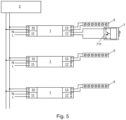
- Fig. 5 again shows a more complex DALI installation with several LED drivers 1 and a higher-level DALI control device 2, which controls the installation.
- a sensor 7 is connected to one of the LED drivers 1 and supplies its recorded environmental data to the LED driver 1.
- the LED driver serves as a kind of gateway, converts the data and sends it to the higher-level control device 2 via the DALI line.
- Fig. 6 shows an embodiment of the interface 17 of the LED driver 1.
- a few additional components are required to detect the sensor signals and supply the sensor.
- the normal function of the voltage supply to the interface is essentially carried out by the two transistors Q1 and Q2, the adjustable voltage reference U2 together with the voltage divider made up of R903 and R904.
- the current is measured via the shunt R902 and the voltage divider R901 and R153. This measurement signal is entered into the analog-digital conversion input ADC of a microcontroller (not shown) for further processing.
- This circuit is adapted by a few additional components for digital data transmission.
- the diode D3 clamps the output voltage to a maximum value because the adjustable voltage reference U2, which reacts quite slowly, causes the output voltage of the interface 17 to overshoot after the output of the interface 17 is short-circuited.
- Resistors R902 and R1 together serve as a current sensing resistor in normal operating mode, where the measured current value correlates with the current at output 13 of the driver.
- the resistor R6 ensures a current limitation of the output current of the LEDset interface.
- an active current limiting circuit can also be used. If this current limitation intervenes, the transistor Q3 goes into saturation and the current gain becomes smaller. As a consequence, the voltage across resistor R901 will increase and will generate a larger signal at the analog-to-digital conversion input ADC. So if the LEDset interface is "short-circuited", a characteristic HIGH signal is generated at the analog-digital conversion input ADC, while the signal is logically LOW if a current of 0mA to 7mA flows at the output of the LEDset interface.
- the thresholds for recognizing a logical HIGH and a logical LOW signal at the output of the LEDset interface 17 must therefore lie between these two characteristic values.
- Fig. 7 shows the characteristic curves in the operating mode explained above.
- Curve 711 shows the voltage at the output of the LEDset interface 17, which is modulated from 5V to 2.7V.
- Curve 731 shows the voltage at the analog-to-digital conversion input ADC of the microcontroller. It can be seen immediately that the voltage at the analog-digital conversion input ADC of the microcontroller can easily be differentiated between logical LOW and logical HIGH if appropriate detection thresholds are set for the two states.
- Fig. 8 shows an embodiment of the interface 71 of the sensor 7. Because the voltage when "short-circuiting" the output of the LEDset interface 17 is not “short-circuited” to 0V but to 2.7V, energy can be supplied to the LEDset interface 17 during both states of the output Sensor can be transferred for operation.
- the components D1, R5 and C7 are required for the separation, buffering and filtering of the 4.5V from the LEDset interface 17.
- the components U1, R6, Q11, Q12, C6, R9 and R10 form a two-quadrant 2.7V power supply.
- the switch M1 does not pull the positive output of the LEDset interface 17 to the negative output, but to the generated 2.7V output. This means that even in the "short-circuited" operating state, the current from the output of the LEDset interface can be used for the 2.7V supply of the sensor 7, which drastically reduces the overall power requirement and greatly increases the performance of the two-quadrant 2.7V power supply of the sensor 7. Because the power supply is designed as a two-quadrant power supply, it can also draw power from the LEDset interface 17 and thus supply the sensor.
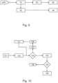
- Fig. 9 shows a schematic status diagram of the software that processes the signals present at the A/D converter of the microcontroller.
- the signal is read into logic 91, which evaluates the signal to determine whether it is a static or a clocked signal.
- the signal is recognized as a static signal, it is passed on to a low-pass filter 93, which generates an analog voltage from the signal. This voltage is then further processed as a measured LED set current 95 in the circuit arrangement, which means that a specific current is set at the output 13 of the circuit arrangement 1 in accordance with the voltage.
- the signal is recognized as a clocked signal, it is entered into a packet decoder 92, which interprets the voltage edges and generates a corresponding bit sequence. This bit sequence is then passed on as a data packet 94 for further processing.
- a status diagram shows a software packet decoder 92, which generates a digital DALI packet from the clocked signal at the second interface 17.
- step 101 the algorithm is in the idle state and waits for the detection of an edge in the signal. If an edge is detected in step 103, then the algorithm checks in step 105 whether all values have already been queried. If this is not the case, then after a short waiting time 107 the value is read in step 109 and then pre-processing takes place in step 111 with regard to the Manchester coding in which the signal is coded. After processing the first value, the query jumps back to whether there are further values that need to be processed. If further values are detected, the processing loop is run again until no further values are detected. If this is the case, all queried values are subjected to Manchester decoding in step 102 to obtain the binary data.
- step 104 This data is then checked for validity in step 104 and discarded in step 106 if errors are detected. If a valid value is recognized, then the data is packed into a DALI package in step 108 and assigned to a DALI library in the circuit arrangement 1. The data can then either be further used in the circuit arrangement 1 itself or forwarded on the DALI bus 15.
Landscapes
- Physics & Mathematics (AREA)
- Life Sciences & Earth Sciences (AREA)
- General Life Sciences & Earth Sciences (AREA)
- General Physics & Mathematics (AREA)
- Geophysics (AREA)
- Circuit Arrangement For Electric Light Sources In General (AREA)
Claims (5)
- Agencement de circuit pour le fonctionnement de sources lumineuses, comprenant :- une entrée (11) pour l'introduction d'une tension d'entrée,- une sortie (13) pour la délivrance d'un courant de sortie,- une première interface (15) pour la commande de l'agencement de circuit,- une deuxième interface (17),l'agencement de circuit étant configuré pour régler deux modes de fonctionnement différents :- dans un premier mode de fonctionnement l'agencement de circuit étant configuré pour être commandé par le biais de la première interface (15) et pour mesurer un courant présent sur la deuxième interface (17) et pour constater un besoin en courant pour la sortie (13) correspondant au courant mesuré,- dans un deuxième mode de fonctionnement, l'agencement de circuit est configuré pour être commandé par le biais de la première interface (15) et pour recevoir une information sur le courant de sortie à régler à la sortie (13),caractérisé en ce quel'agencement de circuit est configuré pour recevoir, par le biais de la deuxième interface (17) dans le deuxième mode de fonctionnement, des informations numériquement codées d'un détecteur (7) raccordé à la deuxième interface (17), pour traiter et transférer à la première interface (15) ces informations de détecteur numériquement codées traitées, etla deuxième interface (17) comprenant une source de tension (Q1, Q2, U2, R903, R904) qui donne une tension prédéterminée, et la source de tension (Q1, Q2, U2, R903, R904) étant réalisée, dans le deuxième mode de fonctionnement, pour alimenter le détecteur (7) en énergie, ainsi qu'un circuit de mesure (R902, R901, R153) pour une tension présente sur la deuxième interface (17), la deuxième interface (17) étant configuré pour, dans le deuxième mode de fonctionnement, recevoir numériquement les informations numériquement codées du détecteur (7) raccordé, par reconnaissance d'une modification de tension synchronisée entre deux tensions différentes à la sortie de la deuxième interface (17), une première tension plus haute et une deuxième tension plus basse de la deuxième interface (17) représentant les états numériques des informations numériquement codées.
- Agencement de circuit selon la revendication 1, caractérisé en ce que les sources lumineuses sont des diodes électroluminescentes ou des modules de diodes électroluminescentes (5).
- Agencement de circuit selon la revendication 1 ou 2, caractérisé en ce que la deuxième interface (17) de l'agencement de circuit comprend en outre un circuit délimitant le courant pour le courant de sortie constitué d'un transistor (Q3) et d'une résistance (R6).
- Agencement de circuit selon la revendication 3, caractérisé en ce que la tension (711) mesurée par le circuit de mesure (R902, R901, R153) dans le premier mode de fonctionnement, présente une corrélation avec le courant de sortie constaté à la sortie (13) de l'agencement de circuit.
- Agencement de circuit selon l'une des revendications précédentes, caractérisé en ce que la deuxième tension la plus basse de 2,7 V sur la deuxième interface (17) représente un un logique et la première tension la plus haute de 5 V de la deuxième interface (17) représente un zéro logique.
Applications Claiming Priority (1)
| Application Number | Priority Date | Filing Date | Title |
|---|---|---|---|
| DE102016226016.2A DE102016226016A1 (de) | 2016-12-22 | 2016-12-22 | SCHALTUNGSANORDNUNG ZUM BETREIBEN VON LICHTQUELLEN UND SENSOR ZUM ANSCHLIEßEN AN EINE SCHALTUNGSANORDNUNG |
Publications (3)
| Publication Number | Publication Date |
|---|---|
| EP3340742A1 EP3340742A1 (fr) | 2018-06-27 |
| EP3340742B1 true EP3340742B1 (fr) | 2024-01-31 |
| EP3340742C0 EP3340742C0 (fr) | 2024-01-31 |
Family
ID=60673538
Family Applications (1)
| Application Number | Title | Priority Date | Filing Date |
|---|---|---|---|
| EP17207197.9A Active EP3340742B1 (fr) | 2016-12-22 | 2017-12-14 | Agencement de circuit permettant le fonctionnement des sources lumineuses |
Country Status (3)
| Country | Link |
|---|---|
| US (1) | US10327301B2 (fr) |
| EP (1) | EP3340742B1 (fr) |
| DE (1) | DE102016226016A1 (fr) |
Families Citing this family (1)
| Publication number | Priority date | Publication date | Assignee | Title |
|---|---|---|---|---|
| CN108541107B (zh) * | 2018-04-28 | 2024-04-12 | 赛尔富电子有限公司 | 一种照明负载异常检测装置及对应的照明系统 |
Family Cites Families (15)
| Publication number | Priority date | Publication date | Assignee | Title |
|---|---|---|---|---|
| US7378805B2 (en) * | 2005-03-22 | 2008-05-27 | Fairchild Semiconductor Corporation | Single-stage digital power converter for driving LEDs |
| DE102007055164B4 (de) * | 2007-11-19 | 2019-06-27 | Tridonic Gmbh & Co Kg | Leuchtmittel-Betriebsgerät zur Datenausgabe, System und elektronisches Vorschaltgerät mit einem derartigen Betriebsgerät |
| US8022634B2 (en) * | 2008-02-05 | 2011-09-20 | Intersil Americas Inc. | Method and system for dimming AC-powered light emitting diode (LED) lighting systems using conventional incandescent dimmers |
| US8593079B2 (en) * | 2010-03-29 | 2013-11-26 | Innosys, Inc | LED dimming driver |
| JP6113417B2 (ja) * | 2011-04-22 | 2017-04-12 | アイリスオーヤマ株式会社 | Ledランプ |
| US9137878B2 (en) * | 2012-03-21 | 2015-09-15 | Osram Sylvania Inc. | Dynamic lighting based on activity type |
| AT14580U1 (de) * | 2013-01-31 | 2016-01-15 | Tridonic Gmbh & Co Kg | Vorrichtung zum Betreiben von LEDs |
| DE102013221496A1 (de) * | 2013-10-23 | 2015-04-23 | Tridonic Gmbh & Co Kg | Betriebsgerät und Verfahren zum Betreiben wenigstens einer Leuchtdiode |
| DE102013222889A1 (de) * | 2013-11-11 | 2015-05-13 | Tridonic Gmbh & Co Kg | LED-Modul, LED-Konverter und Verfahren zum Betreiben wenigstens einer Leuchtdiode |
| DE102013226964A1 (de) * | 2013-12-20 | 2015-06-25 | Tridonic Gmbh & Co Kg | LED-Treiber zum Auslesen von Information eines LED-Moduls |
| DE102014104447A1 (de) * | 2014-03-28 | 2015-10-01 | Bag Engineering Gmbh | Elektronisches Vorschaltgerät für LED-Leuchtmittel |
| DE102014208710A1 (de) * | 2014-05-09 | 2015-11-26 | Tridonic Gmbh & Co Kg | Betriebsgerät, Leuchte und Verfahren zum Versorgen eines LED-Moduls |
| EP3001778B1 (fr) * | 2014-09-29 | 2018-12-19 | Helvar Oy Ab | Dispositif accessoire connectable à un dispositif de commande |
| US9743474B2 (en) * | 2014-11-14 | 2017-08-22 | General Electric Company | Method and system for lighting interface messaging with reduced power consumption |
| EP3123937B1 (fr) * | 2015-07-28 | 2019-08-28 | ams AG | Agencement de capteur biométrique et procédé de génération d'un signal biométrique |
-
2016
- 2016-12-22 DE DE102016226016.2A patent/DE102016226016A1/de not_active Withdrawn
-
2017
- 2017-12-14 EP EP17207197.9A patent/EP3340742B1/fr active Active
- 2017-12-19 US US15/846,278 patent/US10327301B2/en active Active
Also Published As
| Publication number | Publication date |
|---|---|
| DE102016226016A1 (de) | 2018-06-28 |
| EP3340742C0 (fr) | 2024-01-31 |
| US10327301B2 (en) | 2019-06-18 |
| EP3340742A1 (fr) | 2018-06-27 |
| US20180184496A1 (en) | 2018-06-28 |
Similar Documents
| Publication | Publication Date | Title |
|---|---|---|
| EP0393233B1 (fr) | Système de transmission de signaux | |
| DE102010031239A1 (de) | LED-Ansteuerung mit getakteter Konstantstromquelle | |
| DE102013001194A1 (de) | LED-Modul. LED-Vorschaltvorrichtung und System aus einem LED-Modul und einer LED-Vorschaltvorrichtung | |
| DE102016103016A1 (de) | Bestromungsschaltung, Leuchte und Beleuchtungssystem | |
| DE10213254A1 (de) | Lastbetriebssystem und Verfahren dazu | |
| EP2939505B1 (fr) | Circuit d'interface pour la transmission de signaux | |
| DE102018205590A1 (de) | Leistungsversorgungsvorrichtung und kommunikationssystem für beleuchtungssysteme mit derselben | |
| EP3340742B1 (fr) | Agencement de circuit permettant le fonctionnement des sources lumineuses | |
| DE102007055164A1 (de) | Leuchtmittel-Betriebsgerät zu Datenausgabe | |
| EP3064041B1 (fr) | Interface à branche d'émission améliorée | |
| EP2882263B1 (fr) | Circuit d'excitation et procédé de fonctionnement d'un tronçon à LED à gradation dans une zone de gradation à deux zones | |
| EP1473976B1 (fr) | Interface pour signaux de commande digitaux ou signaux de commande par le réseau et méthode de dimensionnement d' un tel interface | |
| EP3235346A1 (fr) | Circuit d'alimentation, appareillage d'alimentation, système d'éclairage et procédé permettant de faire fonctionner au moins une diode électroluminescente | |
| DE102016105739B4 (de) | Vorrichtung mit galvanischer Trennung von einem Kommunikationsbus für mehrere Kommunikationsstandards und entsprechendes Verfahren zur Datenübertragung über eine solche Vorrichtung | |
| EP3123821B1 (fr) | Circuit d'alimentation en tension pour faire fonctionner des led | |
| EP3689112B1 (fr) | Possibilité de signalisation étendue dans un système dali | |
| DE102015200128A1 (de) | Leuchtmittel-Konverter und Leuchtmittel-Modul mit Zweidraht-Kommunikation | |
| DE102007013758A1 (de) | Schnittstelle mit temperaturkompensiertem Sendezweig | |
| EP3100591B1 (fr) | Détection d'un module led | |
| DE202019104171U1 (de) | Treiber | |
| EP3627973B1 (fr) | Procédé de fonctionnement d'un module de consommateur électrique ainsi que système de consommateur électrique | |
| DE102016118085A1 (de) | Verfahren und sensorvorrichtung zur steuerung einer beleuchtungseinrichtung in einem beleuchtungssystem sowie beleuchtungssystem hierzu | |
| WO2012146393A1 (fr) | Ballast électronique pour un appareil d'éclairage | |
| LU93231B1 (de) | Kommunikationssystem zur strommodulierten Datenübertragung über eine Stromschleife | |
| AT18171U1 (de) | Beleuchtungssystem mit Photovoltaikzelle als Umgebungslichtsensor |
Legal Events
| Date | Code | Title | Description |
|---|---|---|---|
| PUAI | Public reference made under article 153(3) epc to a published international application that has entered the european phase |
Free format text: ORIGINAL CODE: 0009012 |
|
| STAA | Information on the status of an ep patent application or granted ep patent |
Free format text: STATUS: THE APPLICATION HAS BEEN PUBLISHED |
|
| AK | Designated contracting states |
Kind code of ref document: A1 Designated state(s): AL AT BE BG CH CY CZ DE DK EE ES FI FR GB GR HR HU IE IS IT LI LT LU LV MC MK MT NL NO PL PT RO RS SE SI SK SM TR |
|
| AX | Request for extension of the european patent |
Extension state: BA ME |
|
| STAA | Information on the status of an ep patent application or granted ep patent |
Free format text: STATUS: REQUEST FOR EXAMINATION WAS MADE |
|
| 17P | Request for examination filed |
Effective date: 20190102 |
|
| RBV | Designated contracting states (corrected) |
Designated state(s): AL AT BE BG CH CY CZ DE DK EE ES FI FR GB GR HR HU IE IS IT LI LT LU LV MC MK MT NL NO PL PT RO RS SE SI SK SM TR |
|
| STAA | Information on the status of an ep patent application or granted ep patent |
Free format text: STATUS: EXAMINATION IS IN PROGRESS |
|
| 17Q | First examination report despatched |
Effective date: 20200408 |
|
| STAA | Information on the status of an ep patent application or granted ep patent |
Free format text: STATUS: EXAMINATION IS IN PROGRESS |
|
| RAP1 | Party data changed (applicant data changed or rights of an application transferred) |
Owner name: OSRAM GMBH |
|
| REG | Reference to a national code |
Ref document number: 502017015801 Country of ref document: DE Ref country code: DE Ref legal event code: R079 Free format text: PREVIOUS MAIN CLASS: H05B0037020000 Ipc: H05B0045220000 |
|
| RIC1 | Information provided on ipc code assigned before grant |
Ipc: H05B 45/10 20200101ALI20221129BHEP Ipc: H05B 47/10 20200101ALI20221129BHEP Ipc: H05B 45/22 20200101AFI20221129BHEP |
|
| GRAP | Despatch of communication of intention to grant a patent |
Free format text: ORIGINAL CODE: EPIDOSNIGR1 |
|
| STAA | Information on the status of an ep patent application or granted ep patent |
Free format text: STATUS: GRANT OF PATENT IS INTENDED |
|
| INTG | Intention to grant announced |
Effective date: 20230110 |
|
| GRAS | Grant fee paid |
Free format text: ORIGINAL CODE: EPIDOSNIGR3 |
|
| RAP1 | Party data changed (applicant data changed or rights of an application transferred) |
Owner name: INVENTRONICS GMBH |
|
| GRAA | (expected) grant |
Free format text: ORIGINAL CODE: 0009210 |
|
| STAA | Information on the status of an ep patent application or granted ep patent |
Free format text: STATUS: THE PATENT HAS BEEN GRANTED |
|
| AK | Designated contracting states |
Kind code of ref document: B1 Designated state(s): AL AT BE BG CH CY CZ DE DK EE ES FI FR GB GR HR HU IE IS IT LI LT LU LV MC MK MT NL NO PL PT RO RS SE SI SK SM TR |
|
| REG | Reference to a national code |
Ref country code: GB Ref legal event code: FG4D Free format text: NOT ENGLISH Ref country code: CH Ref legal event code: EP |
|
| REG | Reference to a national code |
Ref country code: DE Ref legal event code: R096 Ref document number: 502017015801 Country of ref document: DE |
|
| REG | Reference to a national code |
Ref country code: IE Ref legal event code: FG4D Free format text: LANGUAGE OF EP DOCUMENT: GERMAN |
|
| U01 | Request for unitary effect filed |
Effective date: 20240228 |
|
| U07 | Unitary effect registered |
Designated state(s): AT BE BG DE DK EE FI FR IT LT LU LV MT NL PT SE SI Effective date: 20240306 |
|
| PG25 | Lapsed in a contracting state [announced via postgrant information from national office to epo] |
Ref country code: IS Free format text: LAPSE BECAUSE OF FAILURE TO SUBMIT A TRANSLATION OF THE DESCRIPTION OR TO PAY THE FEE WITHIN THE PRESCRIBED TIME-LIMIT Effective date: 20240531 |
|
| PG25 | Lapsed in a contracting state [announced via postgrant information from national office to epo] |
Ref country code: GR Free format text: LAPSE BECAUSE OF FAILURE TO SUBMIT A TRANSLATION OF THE DESCRIPTION OR TO PAY THE FEE WITHIN THE PRESCRIBED TIME-LIMIT Effective date: 20240501 |
|
| PG25 | Lapsed in a contracting state [announced via postgrant information from national office to epo] |
Ref country code: RS Free format text: LAPSE BECAUSE OF FAILURE TO SUBMIT A TRANSLATION OF THE DESCRIPTION OR TO PAY THE FEE WITHIN THE PRESCRIBED TIME-LIMIT Effective date: 20240430 Ref country code: HR Free format text: LAPSE BECAUSE OF FAILURE TO SUBMIT A TRANSLATION OF THE DESCRIPTION OR TO PAY THE FEE WITHIN THE PRESCRIBED TIME-LIMIT Effective date: 20240131 |
|
| PG25 | Lapsed in a contracting state [announced via postgrant information from national office to epo] |
Ref country code: ES Free format text: LAPSE BECAUSE OF FAILURE TO SUBMIT A TRANSLATION OF THE DESCRIPTION OR TO PAY THE FEE WITHIN THE PRESCRIBED TIME-LIMIT Effective date: 20240131 |
|
| PG25 | Lapsed in a contracting state [announced via postgrant information from national office to epo] |
Ref country code: RS Free format text: LAPSE BECAUSE OF FAILURE TO SUBMIT A TRANSLATION OF THE DESCRIPTION OR TO PAY THE FEE WITHIN THE PRESCRIBED TIME-LIMIT Effective date: 20240430 Ref country code: NO Free format text: LAPSE BECAUSE OF FAILURE TO SUBMIT A TRANSLATION OF THE DESCRIPTION OR TO PAY THE FEE WITHIN THE PRESCRIBED TIME-LIMIT Effective date: 20240430 Ref country code: IS Free format text: LAPSE BECAUSE OF FAILURE TO SUBMIT A TRANSLATION OF THE DESCRIPTION OR TO PAY THE FEE WITHIN THE PRESCRIBED TIME-LIMIT Effective date: 20240531 Ref country code: HR Free format text: LAPSE BECAUSE OF FAILURE TO SUBMIT A TRANSLATION OF THE DESCRIPTION OR TO PAY THE FEE WITHIN THE PRESCRIBED TIME-LIMIT Effective date: 20240131 Ref country code: GR Free format text: LAPSE BECAUSE OF FAILURE TO SUBMIT A TRANSLATION OF THE DESCRIPTION OR TO PAY THE FEE WITHIN THE PRESCRIBED TIME-LIMIT Effective date: 20240501 Ref country code: ES Free format text: LAPSE BECAUSE OF FAILURE TO SUBMIT A TRANSLATION OF THE DESCRIPTION OR TO PAY THE FEE WITHIN THE PRESCRIBED TIME-LIMIT Effective date: 20240131 |
|
| PG25 | Lapsed in a contracting state [announced via postgrant information from national office to epo] |
Ref country code: PL Free format text: LAPSE BECAUSE OF FAILURE TO SUBMIT A TRANSLATION OF THE DESCRIPTION OR TO PAY THE FEE WITHIN THE PRESCRIBED TIME-LIMIT Effective date: 20240131 |
|
| PG25 | Lapsed in a contracting state [announced via postgrant information from national office to epo] |
Ref country code: PL Free format text: LAPSE BECAUSE OF FAILURE TO SUBMIT A TRANSLATION OF THE DESCRIPTION OR TO PAY THE FEE WITHIN THE PRESCRIBED TIME-LIMIT Effective date: 20240131 |
|
| PG25 | Lapsed in a contracting state [announced via postgrant information from national office to epo] |
Ref country code: SM Free format text: LAPSE BECAUSE OF FAILURE TO SUBMIT A TRANSLATION OF THE DESCRIPTION OR TO PAY THE FEE WITHIN THE PRESCRIBED TIME-LIMIT Effective date: 20240131 |