EP3340742B1 - Circuit assembly for operating of light sources - Google Patents
Circuit assembly for operating of light sources Download PDFInfo
- Publication number
- EP3340742B1 EP3340742B1 EP17207197.9A EP17207197A EP3340742B1 EP 3340742 B1 EP3340742 B1 EP 3340742B1 EP 17207197 A EP17207197 A EP 17207197A EP 3340742 B1 EP3340742 B1 EP 3340742B1
- Authority
- EP
- European Patent Office
- Prior art keywords
- interface
- circuit arrangement
- sensor
- voltage
- output
- Prior art date
- Legal status (The legal status is an assumption and is not a legal conclusion. Google has not performed a legal analysis and makes no representation as to the accuracy of the status listed.)
- Active
Links
- 238000000034 method Methods 0.000 claims description 5
- 239000000243 solution Substances 0.000 description 11
- 238000009434 installation Methods 0.000 description 10
- 238000006243 chemical reaction Methods 0.000 description 9
- 230000005540 biological transmission Effects 0.000 description 5
- 230000001419 dependent effect Effects 0.000 description 5
- 238000001514 detection method Methods 0.000 description 5
- 238000012545 processing Methods 0.000 description 5
- 238000013461 design Methods 0.000 description 4
- 238000010586 diagram Methods 0.000 description 4
- 238000007781 pre-processing Methods 0.000 description 3
- 238000011161 development Methods 0.000 description 2
- 238000005265 energy consumption Methods 0.000 description 2
- 238000005516 engineering process Methods 0.000 description 2
- 230000003068 static effect Effects 0.000 description 2
- 241001136792 Alle Species 0.000 description 1
- 230000003139 buffering effect Effects 0.000 description 1
- 230000007613 environmental effect Effects 0.000 description 1
- 238000001914 filtration Methods 0.000 description 1
- 230000004907 flux Effects 0.000 description 1
- 238000002955 isolation Methods 0.000 description 1
- 238000005259 measurement Methods 0.000 description 1
- 238000004806 packaging method and process Methods 0.000 description 1
- 238000000926 separation method Methods 0.000 description 1
Images


Classifications
-
- H—ELECTRICITY
- H05—ELECTRIC TECHNIQUES NOT OTHERWISE PROVIDED FOR
- H05B—ELECTRIC HEATING; ELECTRIC LIGHT SOURCES NOT OTHERWISE PROVIDED FOR; CIRCUIT ARRANGEMENTS FOR ELECTRIC LIGHT SOURCES, IN GENERAL
- H05B45/00—Circuit arrangements for operating light-emitting diodes [LED]
- H05B45/20—Controlling the colour of the light
- H05B45/22—Controlling the colour of the light using optical feedback
-
- G—PHYSICS
- G01—MEASURING; TESTING
- G01V—GEOPHYSICS; GRAVITATIONAL MEASUREMENTS; DETECTING MASSES OR OBJECTS; TAGS
- G01V8/00—Prospecting or detecting by optical means
- G01V8/10—Detecting, e.g. by using light barriers
-
- H—ELECTRICITY
- H05—ELECTRIC TECHNIQUES NOT OTHERWISE PROVIDED FOR
- H05B—ELECTRIC HEATING; ELECTRIC LIGHT SOURCES NOT OTHERWISE PROVIDED FOR; CIRCUIT ARRANGEMENTS FOR ELECTRIC LIGHT SOURCES, IN GENERAL
- H05B45/00—Circuit arrangements for operating light-emitting diodes [LED]
- H05B45/10—Controlling the intensity of the light
-
- H—ELECTRICITY
- H05—ELECTRIC TECHNIQUES NOT OTHERWISE PROVIDED FOR
- H05B—ELECTRIC HEATING; ELECTRIC LIGHT SOURCES NOT OTHERWISE PROVIDED FOR; CIRCUIT ARRANGEMENTS FOR ELECTRIC LIGHT SOURCES, IN GENERAL
- H05B47/00—Circuit arrangements for operating light sources in general, i.e. where the type of light source is not relevant
- H05B47/10—Controlling the light source
- H05B47/105—Controlling the light source in response to determined parameters
- H05B47/11—Controlling the light source in response to determined parameters by determining the brightness or colour temperature of ambient light
-
- Y—GENERAL TAGGING OF NEW TECHNOLOGICAL DEVELOPMENTS; GENERAL TAGGING OF CROSS-SECTIONAL TECHNOLOGIES SPANNING OVER SEVERAL SECTIONS OF THE IPC; TECHNICAL SUBJECTS COVERED BY FORMER USPC CROSS-REFERENCE ART COLLECTIONS [XRACs] AND DIGESTS
- Y02—TECHNOLOGIES OR APPLICATIONS FOR MITIGATION OR ADAPTATION AGAINST CLIMATE CHANGE
- Y02B—CLIMATE CHANGE MITIGATION TECHNOLOGIES RELATED TO BUILDINGS, e.g. HOUSING, HOUSE APPLIANCES OR RELATED END-USER APPLICATIONS
- Y02B20/00—Energy efficient lighting technologies, e.g. halogen lamps or gas discharge lamps
- Y02B20/40—Control techniques providing energy savings, e.g. smart controller or presence detection
Definitions
- the invention relates to a circuit arrangement for operating light sources.
- the invention is based on a circuit arrangement for operating light sources according to the preamble of the main claim.
- a device for operating LEDs which has an output to which an LED module can be connected.
- An interface is also provided, which is also connected to the LED module can be used to regulate or query parameters of the LED module.
- an LED converter and an LED module are known, which can be connected to one another via a wireless interface for the purpose of operating the LED module.
- the energy for operating the LED module is also transmitted wirelessly.
- LED technology not only enables the development of ever more efficient lights, but also offers new design freedom. In addition to the possibility of flexible arrangement of the individual LEDs on freely designable circuit board shapes / circuit board formats, this freedom of design results in particular from the low height of the LED modules.
- the limitation of the minimum height of the luminaire that can be achieved is currently determined solely by the height of the LED driver and the light control components to be integrated into the luminaire.
- the lighting industry faces two problems that need to be solved at the same time: firstly, the need for simple, cost-effective daylight and presence-dependent lighting control solutions that consist of as few components as possible.
- the height of the components used should be as low as possible, while at the same time a permanent, efficient energy supply is required.
- the solutions currently available on the market are based on the de facta standard height of the LED drivers of 21 mm.
- the solutions for individual lights consist of one or more dimmable LED drivers, a control device and at least one light/presence sensor.
- the object is achieved according to the invention with a circuit arrangement for operating light sources, having an input for inputting an input voltage, an output for outputting an output current, a first interface for controlling the circuit arrangement and a second interface, the circuit arrangement being set up to have two different operating modes to set.
- a first operating mode the circuit arrangement is set up to be controlled via the first interface and to measure a current present at the second interface and to determine a current requirement for the output in accordance with the measured current.
- the circuit arrangement is set up to be controlled via the first interface and to receive the information about the output current to be set at the output, as well as to receive and process digitally coded information from a sensor connected to the second interface via the second interface to pass on processed digitally coded sensor information to the first interface.
- Controlling the circuit arrangement means, for example, switching the light sources connected to the circuit arrangement on and off and dimming these light sources.
- the solution according to the invention uses the second interface present in the circuit arrangement.
- the second interface is an LEDset interface.
- the current strength for the LED modules connected to the driver is set via the LEDset interface by connecting an external resistor.
- this function is increasingly being replaced by programming via the first interface, which is a DALI interface, or via NFC technology using software.
- the current values programmed in this way have priority over the settings that would be specified via the resistor on the LEDset interface.
- the invention uses the LEDset interface for the alternative connection of a light and presence sensor. This sensor periodically sends digitally coded light values and presence events to the circuit arrangement by modulating information via the LEDset interface using two different voltages. At the same time, the LEDset interface serves to supply the sensor with energy.
- the circuit arrangement automatically recognizes the sensor connection as soon as it receives corresponding telegrams. Since the LED set interfaces of different circuit arrangements are generally not allowed to be connected to one another in order to prevent unwanted current flows and shifts in voltage levels, another circuit arrangement cannot simply be connected in parallel. For this reason, the sensor for connecting a further circuit arrangement has an additional interface that is galvanically isolated via an optocoupler, via which the second circuit arrangement receives identical information as the first.
- the light sources are light-emitting diodes or light-emitting diode modules.
- Light-emitting diode modules are modules built on a circuit board with several LEDs connected in series and/or series and additional electronics that regulate the power requirements of the LEDs. These have a high level of efficiency and have recently also had increasingly higher light packages, meaning that more and more lighting tasks can be solved with these light sources.
- the second interface has a voltage source that outputs a predetermined voltage, the voltage source (Q1, Q2, U2, R903, R904) being designed to supply energy to the sensor (7) in the second operating mode, and the second interface also has a measuring circuit for a voltage present at the second interface.
- the voltage source Q1, Q2, U2, R903, R904
- the second interface also has a measuring circuit for a voltage present at the second interface.
- the voltage source of the second interface only acts like a voltage source up to a certain output current of the second interface. This ensures safe operation in mode for receiving digital data from a connected sensor.
- the voltage measured by the measuring circuit correlates with the detected output current at the output of the circuit arrangement. This measure advantageously implements the LEDset standard for adjusting the output current of the driver via a current setting resistor at the second interface.
- the second interface is set up to receive the information from the sensor digitally by detecting a clocked voltage change between two different voltages at the output of the second interface.
- Clocked voltage change here means imprinting digital information by impressing two different voltage levels into the output of the second interface.
- Various digital coding methods such as Manchester coding can be used. This advantageously ensures a continuous power supply to the sensor.
- the voltage source of the second interface is therefore used to supply energy to the sensor. Because two different voltage levels are used for the information transmission, energy is advantageously transmitted to the sensor to supply the sensor with energy during the entire transmission period of the transmission of digital information.
- a voltage of 2.7V at the second interface represents a logical one and a voltage of 5V at the second interface represents a logical zero.
- An embodiment not according to the invention represents a sensor for connection to a circuit arrangement, the sensor having a first interface for transmitting information recorded by the sensor to the circuit arrangement, the sensor being set up to transmit the transmitted information digitally via binary signals at the first interface , and the sensor is set up to be powered via this interface. Due to the combined transmission of data and the power supply of the sensor, the entire arrangement is very efficient in energy consumption and it becomes additional components and terminals on the circuit arrangement side and on the sensor side are also saved.
- the senor has a galvanically isolated second interface for transmitting information to another circuit arrangement.
- two circuit arrangements such as LED drivers can advantageously be supplied with sensor information at the same time. Since they can then react immediately, this arrangement can be used advantageously in lights with high light packages, where an LED driver alone is too weak.
- the binary signals are formed by impressing two different voltages on the first interface and/or the second interface.
- the different voltages can advantageously be 2.7V and 5V, for example. Since the sensor requires 2.7V for its power supply, it can be continuously supplied with power via the interface and the energy efficiency of the entire arrangement increases.
- a voltage of 2.7V at the first interface represents a logic one and a voltage of 5V at the first interface represents a logic zero.
- the information sent represents brightness values of the light measured by the sensor (7). This means that a daylight-dependent light control can preferably be implemented, which saves energy.
- the information sent by the sensor (7) represents presence events measured.
- the light can advantageously be switched off or dimmed when people are not present in order to save further energy.
- the circuit arrangement 1 is preferably an LED driver, an electronic ballast for LEDs and LED modules. Therefore, the term LED driver is used synonymously with the term circuit arrangement in the following.
- the LED driver also has two interfaces, the first interface is a DALI interface.
- DALI Digital Addressable Light Interface
- the second interface 17 is an LEDset interface, via which the power requirement of all connected LED modules is reported to the circuit arrangement.
- the LEDset interface is a very simple and functional analog interface which is becoming more and more popular in the lighting sector.
- Fig. 1 shows a preferred embodiment of the circuit arrangement 1 in a first operating mode, in which an LED module 5 is connected to the output 13 and an interface 57 with a current setting circuit is connected to the second interface 17 of the circuit arrangement.
- the LED module 5 itself can also have an interface 57 with the current setting circuit, which is connected to the second interface 17 of the LED driver in order to report the power requirement of the LED module 5 to the circuit arrangement.
- the LED driver 1 has a voltage source which is coupled to the second interface 17.
- a current measuring device is connected to the second interface 17. The second interface therefore impresses a predetermined voltage into the LED module 5 via the voltage source and thereby measures the current that is present at the second interface.
- the measured current determines the output current that the circuit arrangement applies to the LED module 5 via the output 13.
- the current is determined by a resistor in the interface 57 (of the LED module 5), the value of which indicates the current requirement of the LED module 5.
- the standard voltage of the interface is 5V.
- the LED driver can be controlled via a first interface 15; in particular, the LED module 5 can be switched on and off and dimmed.
- the first interface 15 is designed here as a DALI interface.
- the circuit arrangement 1 also has an input 11 for entering an input voltage.
- the input voltage can be an alternating mains voltage or a direct voltage (for LED drivers with emergency power capability).
- Fig. 2 shows the preferred embodiment of the LED driver 1 in a second operating mode, in which an LED module 5 is connected to the output 13 and a sensor 7 to the second interface 17.
- the output current of the LED driver 1 for the LED module 5 is set via the first interface 15.
- the current value can be transferred digitally and stored permanently in the circuit arrangement 1.
- a sensor 7 is connected to the second interface 17. Since the second interface 17 is an LEDSet interface, the sensor can be powered via the voltage source.
- the voltage source is designed so that it only works as a voltage source up to a certain maximum current. If this maximum current is exceeded, the voltage at the interface is no longer maintained and collapses. This ensures efficient operation of the second interface 17.
- the maximum current is dimensioned so that all known resistors, which represent the current requirements of the known modules, can still be reliably identified via the voltage dropped across the resistor. In this case the maximum current is set at 6mA. If different voltage levels are periodically impressed on the second interface 17 by the sensor 7 via the sensor interface 71 in order to transmit digital data, the output current is a maximum of 6mA. This means that the losses at the interface are not too high.
- the 6mA is enough to supply the sensor with the necessary power for its operation.
- Fig. 3 shows the LED driver 1 in another operating mode in which a button to control the LED driver is connected to the first (DALI) interface.
- the LED module 5 can be switched on and off and dimmed using the button.
- the term “touch dim” has become commonplace for this.
- Using the DALI interface for this is known in the prior art.
- the combination with a button for control can be used advantageously in simple installations without a networked control system.
- the sensor can be used here, for example, to maintain a specific illuminance, whereby the LED module 5 is then operated more or less dimmed depending on the daylight.
- FIG. 4 A further variant of the described installation is shown Fig. 4 .
- Two LED drivers 1 are used here to operate two LED modules 5 with a button control and a sensor 7.
- the sensor 7 has two galvanically isolated interfaces 71 and 73, each of which is connected to an LED driver 1.
- the interface 71 simultaneously provides power to the sensor 7 via the first LED driver 1.
- the same information is output to the second driver 1 via the galvanically isolated interface 73, so that both LED modules 5 connected to the two LED drivers provide the same light, motion and and receive brightness information from the sensor. Since the LED set interfaces 17 of the LED drivers cannot be connected together, galvanic isolation is necessary.
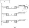
- Fig. 5 again shows a more complex DALI installation with several LED drivers 1 and a higher-level DALI control device 2, which controls the installation.
- a sensor 7 is connected to one of the LED drivers 1 and supplies its recorded environmental data to the LED driver 1.
- the LED driver serves as a kind of gateway, converts the data and sends it to the higher-level control device 2 via the DALI line.
- Fig. 6 shows an embodiment of the interface 17 of the LED driver 1.
- a few additional components are required to detect the sensor signals and supply the sensor.
- the normal function of the voltage supply to the interface is essentially carried out by the two transistors Q1 and Q2, the adjustable voltage reference U2 together with the voltage divider made up of R903 and R904.
- the current is measured via the shunt R902 and the voltage divider R901 and R153. This measurement signal is entered into the analog-digital conversion input ADC of a microcontroller (not shown) for further processing.
- This circuit is adapted by a few additional components for digital data transmission.
- the diode D3 clamps the output voltage to a maximum value because the adjustable voltage reference U2, which reacts quite slowly, causes the output voltage of the interface 17 to overshoot after the output of the interface 17 is short-circuited.
- Resistors R902 and R1 together serve as a current sensing resistor in normal operating mode, where the measured current value correlates with the current at output 13 of the driver.
- the resistor R6 ensures a current limitation of the output current of the LEDset interface.
- an active current limiting circuit can also be used. If this current limitation intervenes, the transistor Q3 goes into saturation and the current gain becomes smaller. As a consequence, the voltage across resistor R901 will increase and will generate a larger signal at the analog-to-digital conversion input ADC. So if the LEDset interface is "short-circuited", a characteristic HIGH signal is generated at the analog-digital conversion input ADC, while the signal is logically LOW if a current of 0mA to 7mA flows at the output of the LEDset interface.
- the thresholds for recognizing a logical HIGH and a logical LOW signal at the output of the LEDset interface 17 must therefore lie between these two characteristic values.
- Fig. 7 shows the characteristic curves in the operating mode explained above.
- Curve 711 shows the voltage at the output of the LEDset interface 17, which is modulated from 5V to 2.7V.
- Curve 731 shows the voltage at the analog-to-digital conversion input ADC of the microcontroller. It can be seen immediately that the voltage at the analog-digital conversion input ADC of the microcontroller can easily be differentiated between logical LOW and logical HIGH if appropriate detection thresholds are set for the two states.
- Fig. 8 shows an embodiment of the interface 71 of the sensor 7. Because the voltage when "short-circuiting" the output of the LEDset interface 17 is not “short-circuited” to 0V but to 2.7V, energy can be supplied to the LEDset interface 17 during both states of the output Sensor can be transferred for operation.
- the components D1, R5 and C7 are required for the separation, buffering and filtering of the 4.5V from the LEDset interface 17.
- the components U1, R6, Q11, Q12, C6, R9 and R10 form a two-quadrant 2.7V power supply.
- the switch M1 does not pull the positive output of the LEDset interface 17 to the negative output, but to the generated 2.7V output. This means that even in the "short-circuited" operating state, the current from the output of the LEDset interface can be used for the 2.7V supply of the sensor 7, which drastically reduces the overall power requirement and greatly increases the performance of the two-quadrant 2.7V power supply of the sensor 7. Because the power supply is designed as a two-quadrant power supply, it can also draw power from the LEDset interface 17 and thus supply the sensor.
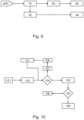
- Fig. 9 shows a schematic status diagram of the software that processes the signals present at the A/D converter of the microcontroller.
- the signal is read into logic 91, which evaluates the signal to determine whether it is a static or a clocked signal.
- the signal is recognized as a static signal, it is passed on to a low-pass filter 93, which generates an analog voltage from the signal. This voltage is then further processed as a measured LED set current 95 in the circuit arrangement, which means that a specific current is set at the output 13 of the circuit arrangement 1 in accordance with the voltage.
- the signal is recognized as a clocked signal, it is entered into a packet decoder 92, which interprets the voltage edges and generates a corresponding bit sequence. This bit sequence is then passed on as a data packet 94 for further processing.
- a status diagram shows a software packet decoder 92, which generates a digital DALI packet from the clocked signal at the second interface 17.
- step 101 the algorithm is in the idle state and waits for the detection of an edge in the signal. If an edge is detected in step 103, then the algorithm checks in step 105 whether all values have already been queried. If this is not the case, then after a short waiting time 107 the value is read in step 109 and then pre-processing takes place in step 111 with regard to the Manchester coding in which the signal is coded. After processing the first value, the query jumps back to whether there are further values that need to be processed. If further values are detected, the processing loop is run again until no further values are detected. If this is the case, all queried values are subjected to Manchester decoding in step 102 to obtain the binary data.
- step 104 This data is then checked for validity in step 104 and discarded in step 106 if errors are detected. If a valid value is recognized, then the data is packed into a DALI package in step 108 and assigned to a DALI library in the circuit arrangement 1. The data can then either be further used in the circuit arrangement 1 itself or forwarded on the DALI bus 15.
Description
Die Erfindung betrifft eine Schaltungsanordnung zum Betreiben von Lichtquellen.The invention relates to a circuit arrangement for operating light sources.
Die Erfindung geht aus von einer Schaltungsanordnung zum Betreiben von Lichtquellen nach der Gattung des Hauptanspruchs.The invention is based on a circuit arrangement for operating light sources according to the preamble of the main claim.
Speziell für intelligente Einzelleuchten (z.B. Stehleuchten) wird zunehmend eine automatische tageslicht-und präsenz-abhängige Lichtsteuerung in Ausschreibungen vorgegeben. Gründe dafür sind gestiegene Komfortansprüche, in Form einer konstanten Beleuchtungsstärke auf der Arbeitsoberfläche, bei gleichzeitig die restriktiveren Vorgaben für den maximalen Energieverbrauch. Hier seien die ENEV bzw. die EPBD genannt. Daher sind zunehmend einfache und kostengünstige Lösungen gefordert. Dies bedeutet u.a. dass die Funktion der Tageslichtregelung und Präsenzerfassung mit möglichst wenigen Komponenten realisiert werden sollte. Diese Komponenten benötigen wie alle elektronischen Geräte eine Energieversorgung die effizient genug ist, um eine geringe Standby Stromaufnahme der Gesamtlösung zu gewährleisten.Automatic daylight and presence-dependent lighting control is increasingly being specified in tenders, especially for intelligent individual lights (e.g. floor lamps). The reasons for this are increased comfort requirements, in the form of constant lighting levels on the work surface, while at the same time the more restrictive requirements for maximum energy consumption. The ENEV and the EPBD should be mentioned here. Therefore, simple and cost-effective solutions are increasingly required. This means, among other things, that the function of daylight control and presence detection should be implemented with as few components as possible. Like all electronic devices, these components require a power supply that is efficient enough to ensure a low standby power consumption for the overall solution.
Aus der
Aus der
Aus der
Die LED Technik ermöglicht nicht nur die Entwicklung immer effizienterer Leuchten, sondern bietet neue Designfreiheiten. Diese Designfreiheit ergibt sich neben der Möglichkeit der flexiblen Anordnung der Einzel LED auf frei gestaltbaren Platinen-Formen / Platinen-Formaten insbesondere auch aus der geringen Bauhöhe der LED Module. Die Limitierung der minimal realisierbaren Leuchtenbauhöhe wird derzeit allein durch die Bauhöhe des LED Treibers und der in die Leuchte zu integrierenden Lichtsteuerkomponenten bestimmt.LED technology not only enables the development of ever more efficient lights, but also offers new design freedom. In addition to the possibility of flexible arrangement of the individual LEDs on freely designable circuit board shapes / circuit board formats, this freedom of design results in particular from the low height of the LED modules. The limitation of the minimum height of the luminaire that can be achieved is currently determined solely by the height of the LED driver and the light control components to be integrated into the luminaire.
Zusammenfassend stellen sich für die Lichtindustrie also zwei gleichzeitig zu lösende Probleme, zum einen der Bedarf an einfachen, kostengünstigen tageslicht-und präsenzabhängigen Lichtsteuerlösungen die aus möglichst wenigen Komponenten besteht. Zum anderen soll die Bauhöhe der eingesetzten Komponenten möglichst gering sein wobei gleichzeitig eine dauerhafte effiziente Energieversorgung erforderlich ist.In summary, the lighting industry faces two problems that need to be solved at the same time: firstly, the need for simple, cost-effective daylight and presence-dependent lighting control solutions that consist of as few components as possible. On the other hand, the height of the components used should be as low as possible, while at the same time a permanent, efficient energy supply is required.
Die bisher am Markt verfügbaren Lösungen orientieren sich an der de Facta Standardbauhöhe der LED Treiber von 21 mm. In der Regel bestehen die Lösungen für Einzelleuchten aus einem oder mehreren dimmbaren LED-Treibern, einem Steuergerät und mindestens einen Licht- / Präsenz-Sensor.The solutions currently available on the market are based on the de facta standard height of the LED drivers of 21 mm. As a rule, the solutions for individual lights consist of one or more dimmable LED drivers, a control device and at least one light/presence sensor.
Bei bereits optimierten/vereinfachten Systemen entfällt das Steuergerät, dies Funktion übernimmt entweder der Sensor oder alternativ der LED Treiber selbst. Für diese Systeme gibt es für den Anschluss des Sensors zwei Lösungen:
- a) Anschluss des Sensors über die bereits vorhandene DALI Schnittstelle des Treibers. Dafür muss die entweder die normalerweise passive DALI Schnittstelle des Treibers zu einer aktiven DALI Schnittstelle modifiziert werden, die einen DALI Strom für die Versorgung externer Komponenten liefert, oder ein DALI Netzteil in den Sensor integriert werden. Nachteil sind zu einen ein höherer Bauteileaufwand und zum anderen eine höhere Standby-Leistung.
- b) Der LED Treiber besitzt eine zusätzliche Schnittstelle für den Sensoranschluss. Hauptnachteil ist der höhere Bauteileaufwand und die zusätzlichen Klemmen.
- a) Connecting the sensor via the driver’s existing DALI interface. To do this, either the driver's normally passive DALI interface must be modified to an active DALI interface that supplies a DALI current to supply external components, or a DALI power supply must be integrated into the sensor. The disadvantage is, on the one hand, a higher cost of components and, on the other hand, a higher standby performance.
- b) The LED driver has an additional interface for the sensor connection. The main disadvantage is the higher cost of components and the additional terminals.
Es ist Aufgabe der Erfindung, einen LED Treiber anzugeben, welcher bei geringer Bauhöhe kostengünstiger herzustellen und einfach zu installieren beziehungsweise zu betreiben ist.It is the object of the invention to provide an LED driver which is cheaper to produce with a low overall height and is easy to install or operate.
Die Lösung der Aufgabe erfolgt erfindungsgemäß mit einer Schaltungsanordnung zum Betreiben von Lichtquellen, aufweisend einen Eingang zum Eingeben einer Eingangsspannung, einen Ausgang zum Ausgeben eines Ausgangsstromes, eine erste Schnittstelle zum Steuern der Schaltungsanordnung und eine zweite Schnittstelle, wobei die Schaltungsanordnung eingerichtet ist, zwei unterschiedliche Betriebsmodi einzustellen. In einem ersten Betriebsmodus ist die Schaltungsanordnung eingerichtet über die erste Schnittstelle gesteuert zu werden und einen an der zweiten Schnittstelle anliegenden Strom zu messen und einen Strombedarf für den Ausgang entsprechend dem gemessenen Strom festzustellen.The object is achieved according to the invention with a circuit arrangement for operating light sources, having an input for inputting an input voltage, an output for outputting an output current, a first interface for controlling the circuit arrangement and a second interface, the circuit arrangement being set up to have two different operating modes to set. In a first operating mode, the circuit arrangement is set up to be controlled via the first interface and to measure a current present at the second interface and to determine a current requirement for the output in accordance with the measured current.
In einem zweiten Betriebsmodus ist die Schaltungsanordnung eingerichtet, über die erste Schnittstelle gesteuert zu werden und die Information über den am Ausgang einzustellenden Ausgangsstrom zu empfangen, sowie über die zweite Schnittstelle digital kodierte Informationen von einem an die zweite Schnittstelle angeschlossenen Sensor zu empfangen, zu verarbeiten, und diese verarbeiteten digital kodierten Sensorinformationen an die erste Schnittstelle weiterzugeben.In one In the second operating mode, the circuit arrangement is set up to be controlled via the first interface and to receive the information about the output current to be set at the output, as well as to receive and process digitally coded information from a sensor connected to the second interface via the second interface to pass on processed digitally coded sensor information to the first interface.
Mit Steuern der Schaltungsanordnung sind hier z.B. das Ein- und Ausschalten der an die Schaltungsanordnung angeschlossenen Lichtquellen sowie das Dimmen dieser Lichtquellen gemeint.Controlling the circuit arrangement here means, for example, switching the light sources connected to the circuit arrangement on and off and dimming these light sources.
Die erfindungsgemäße Lösung nutzt die bei der Schaltungsanordnung vorhandene zweite Schnittstelle. Die zweite Schnittstelle ist eine LEDset Schnittstelle. Über die LEDset Schnittstelle wird über den Anschluss eines externen Widerstandes die Stromstärke für die an den Treiber angeschlossenen LED Module eingestellt. Diese Funktion wird allerdings mehr und mehr durch eine Programmierung über die erste Schnittstelle, welche eine DALI Schnittstelle ist, oder über NFC Technologie mittels einer Software ersetzt. Die so programmierten Stromwerte haben Vorrang vor den Einstellungen die über den Widerstand an der LEDset Schnittstelle vorgegeben werden würden. Die Erfindung nutzt die LEDset Schnittstelle für den alternativen Anschluss eines Licht- und Präsenz-Sensors. Dieser Sensor sendet periodisch Lichtwerte und Präsenzereignisse digital kodiert an die Schaltungsanordnung in dem er Informationen über die LEDset Schnittstelle mittels zwei verschiedener Spannungen aufmoduliert. Gleichzeitig dient die LEDset Schnittstelle der Energieversorgung des Sensors. Die Schaltungsanordnung erkennt den Sensoranschluss automatisch, sobald er entsprechende Telegramme erhält. Da die LEDset Schnittstellen unterschiedlicher Schaltungsanordnungen in der Regel nicht miteinander verbunden werden dürfen, um ungewollte Stromflüsse und Verschiebung von Spannungspegeln zu verhindern, kann eine weitere Schaltungsanordnung nicht einfach parallel geschaltet werden. Deshalb besitzt der Sensor zum Anschluss einer weiteren Schaltungsanordnung eine zusätzliche über einen Optokoppler galvanisch abgetrennte Schnittstelle, über diese erhält die zweite Schaltungsanordnung identische Informationen wie die erste.The solution according to the invention uses the second interface present in the circuit arrangement. The second interface is an LEDset interface. The current strength for the LED modules connected to the driver is set via the LEDset interface by connecting an external resistor. However, this function is increasingly being replaced by programming via the first interface, which is a DALI interface, or via NFC technology using software. The current values programmed in this way have priority over the settings that would be specified via the resistor on the LEDset interface. The invention uses the LEDset interface for the alternative connection of a light and presence sensor. This sensor periodically sends digitally coded light values and presence events to the circuit arrangement by modulating information via the LEDset interface using two different voltages. At the same time, the LEDset interface serves to supply the sensor with energy. The circuit arrangement automatically recognizes the sensor connection as soon as it receives corresponding telegrams. Since the LED set interfaces of different circuit arrangements are generally not allowed to be connected to one another in order to prevent unwanted current flows and shifts in voltage levels, another circuit arrangement cannot simply be connected in parallel. For this reason, the sensor for connecting a further circuit arrangement has an additional interface that is galvanically isolated via an optocoupler, via which the second circuit arrangement receives identical information as the first.
Diese Ausgestaltung weist mehrere Vorteile auf:
- a) der Sensor nutzt die bestehende LEDset Schnittstelle und meldet sich selbständig an.
Vorteile:- Keine weitere Schnittstelle an der Schaltungsanordnung erforderlich.
- Wenn kein Sensor angeschlossen ist, bleibt die normale LEDset Funktion zur Einstellung der LED Modul Bestromung erhalten.
- b) Der Sensor benötigt keine eigene Netzversorgung, die Versorgung erfolgt direkt über die Schaltungsanordnung.
Vorteile:- Die Bauhöhe des Sensors kann reduziert werden.
- Die Standby Leistung des Systems Schaltungsanordnung / Sensor erhöht sich gegenüber der des Treibers ohne Sensor nur minimal.
- c) Durch eine zusätzliche passive, galvanisch abgetrennte Schnittstelle am Sensor lässt sich ein zweiter Treiber anschließen.
Vorteil:- Die Lösung ist auch für Leuchten mit höherem Lichtstrom geeignet.
- d) Die erste Schnittstelle (DALI Interface) des Treibers bleibt verfügbar.
Vorteile:- Über den Anschluss eines Tasters kann eine zusätzliche manuelle Bedienung (Schalten/Dimmen/Sollwertspeicherung) realisiert werden
- In einer Weiterentwicklung der erfindungsgemäßen Lösung, kann die Kombination aus Schaltungsanordnung und Sensor über die DALI Leitung in eine DALI Installation eingebunden werden. Dabei arbeitet die Schaltungsanordnung zusätzlich als "DALI Sensor Koppler" und gibt die Licht- und Präsenzinformationen des angeschlossenen Sensors über entsprechende DALI Telegramme an eine übergeordnete DALI Steuereinheit weiter.
- a) the sensor uses the existing LEDset interface and logs in independently.
Advantages:- No further interface on the circuit arrangement required.
- If no sensor is connected, the normal LEDset function for setting the LED module power supply remains intact.
- b) The sensor does not require its own power supply; the supply is provided directly via the circuit arrangement.
Advantages:- The height of the sensor can be reduced.
- The standby performance of the system circuit arrangement/sensor increases only minimally compared to that of the driver without a sensor.
- c) A second driver can be connected via an additional passive, galvanically isolated interface on the sensor.
Advantage:- The solution is also suitable for luminaires with higher luminous flux.
- d) The first interface (DALI interface) of the driver remains available.
Advantages:- Additional manual operation (switching/dimming/setpoint storage) can be implemented by connecting a button
- In a further development of the solution according to the invention, the combination of circuit arrangement and sensor can be integrated into a DALI installation via the DALI line. The circuit arrangement also works as a “DALI sensor coupler” and provides the light and presence information of the connected sensor via corresponding DALI telegrams to a higher-level DALI control unit.
In einer besonders bevorzugten Ausführungsform sind die Lichtquellen Leuchtdioden oder Leuchtdiodenmodule. Leuchtdiodenmodule sind hier auf einer Leiterplatte aufgebaute Module mit mehreren seriell und/oder in Reihe geschalteten LEDs und zusätzlicher Elektronik, die den Strombedarf der LEDs regeln. Diese weisen eine hohe Effizienz auf und haben in jüngerer Zeit auch immer höhere Lichtpakete so dass immer mehr Beleuchtungsaufgaben mit diesen Lichtquellen gelöst werden können.In a particularly preferred embodiment, the light sources are light-emitting diodes or light-emitting diode modules. Light-emitting diode modules are modules built on a circuit board with several LEDs connected in series and/or series and additional electronics that regulate the power requirements of the LEDs. These have a high level of efficiency and have recently also had increasingly higher light packages, meaning that more and more lighting tasks can be solved with these light sources.
Erfindungsgemäß weist die zweite Schnittstelle eine Spannungsquelle auf, die eine vorbestimmte Spannung abgibt, wobei die Spannungsquelle (Q1, Q2, U2, R903, R904) im zweiten Betriebsmodus zur Energieversorgung des Sensors (7) ausgebildet ist, und weiterhin weist die zweite Schnittstelle eine Messschaltung für eine an der zweiten Schnittstelle anliegenden Spannung auf. Damit kann vorteilhaft sowohl das LEDset Protokoll realisiert werden als auch ein digitales Protokoll zum Empfangen von Sensordaten.According to the invention, the second interface has a voltage source that outputs a predetermined voltage, the voltage source (Q1, Q2, U2, R903, R904) being designed to supply energy to the sensor (7) in the second operating mode, and the second interface also has a measuring circuit for a voltage present at the second interface. This means that both the LEDset protocol and a digital protocol for receiving sensor data can be advantageously implemented.
In einer nicht erfindungsgemäßen Ausführungsform wirkt die Spannungsquelle der zweiten Schnittstelle nur bis zu einem bestimmten Ausgangsstrom der zweiten Schnittstelle wie eine Spannungsquelle. Dies stellt einen sicheren Betrieb im Modus zum Empfangen digitaler Daten von einem angeschlossenen Sensor sicher.In an embodiment not according to the invention, the voltage source of the second interface only acts like a voltage source up to a certain output current of the second interface. This ensures safe operation in mode for receiving digital data from a connected sensor.
In einer besonders bevorzugten Ausführungsform korreliert die von der Messschaltung gemessene Spannung mit dem festgestellten Ausgangsstrom am Ausgang der Schaltungsanordnung. Diese Maßnahme realisiert vorteilhaft den LEDset Standard zur Einstellung des Ausgangsstroms des Treibers über einen Stromsetzwiderstand an der zweiten Schnittstelle.In a particularly preferred embodiment, the voltage measured by the measuring circuit correlates with the detected output current at the output of the circuit arrangement. This measure advantageously implements the LEDset standard for adjusting the output current of the driver via a current setting resistor at the second interface.
Erfindungsgemäß ist die zweite Schnittstelle eingerichtet, die Informationen von dem Sensor digital durch Erkennen einer getakteten Spannungsänderung zwischen zwei unterschiedlichen Spannungen am Ausgang der zweiten Schnittstelle zu empfangen. Mit getakteter Spannungsänderung ist hier ein Aufprägen digitaler Information durch einprägen zweier verschiedener Spannungsniveaus in den Ausgang der zweiten Schnittstelle gemeint. So kann eine erste höhere Spannung von z.B. 5V (= binär 0) und eine zweite Spannung von z.B. 2,7V (=binär 1) der zweiten Schnittstelle digitale Zustände repräsentieren, über die bitweise Informationen übertragen werden. Dabei können verschiedene digitale Kodierverfahren wie z.B. die Manchestercodierung verwendet werden. Vorteilhaft stellt dies eine kontinuierliche Spannungsversorgung des Sensors sicher.According to the invention, the second interface is set up to receive the information from the sensor digitally by detecting a clocked voltage change between two different voltages at the output of the second interface. Clocked voltage change here means imprinting digital information by impressing two different voltage levels into the output of the second interface. A first higher voltage of, for example, 5V (=binary 0) and a second voltage of, for example, 2.7V (=binary 1) of the second interface can represent digital states via which bit-by-bit information is transmitted. Various digital coding methods such as Manchester coding can be used. This advantageously ensures a continuous power supply to the sensor.
Damit dient die Spannungsquelle der zweiten Schnittstelle erfindungsgemäß zur Energieversorgung des Sensors. Dadurch, dass für die Informationsübertragung zwei unterschiedliche Spannungsniveaus verwendet werden, wird während der gesamten Übertragungsdauer der Übertragung digitaler Informationen gleichzeitig vorteilhaft Energie an den Sensor zur Energieversorgung des Sensors übertragen.According to the invention, the voltage source of the second interface is therefore used to supply energy to the sensor. Because two different voltage levels are used for the information transmission, energy is advantageously transmitted to the sensor to supply the sensor with energy during the entire transmission period of the transmission of digital information.
Bevorzugt repräsentiert eine Spannung von 2,7V an der zweiten Schnittstelle eine logische Eins und eine Spannung von 5V der zweiten Schnittstelle eine logische Null. Mit diesen zwei Spannungsniveaus kann gleichzeitig vorteilhaft die Stromversorgung des Sensors sichergestellt werden und andererseits eine einfache und zuverlässige Erkennung der digital übertragenen Werte sichergestellt werden.Preferably, a voltage of 2.7V at the second interface represents a logical one and a voltage of 5V at the second interface represents a logical zero. With these two voltage levels, the power supply to the sensor can be advantageously ensured at the same time and, on the other hand, simple and reliable detection of the digitally transmitted values can be ensured.
Eine nicht erfindungsgemäße Ausführungsform stellt einen Sensor zum Anschließen an eine Schaltungsanordnung dar, wobei der Sensor eine erste Schnittstelle zum Übertragen von vom Sensor erfassten Informationen an die Schaltungsanordnung aufweist, wobei der Sensor eingerichtet ist, die gesendeten Informationen digital über Binärsignale an der ersten Schnittstelle zu übertragen, und wobei der Sensor eingerichtet ist, über diese Schnittstelle mit Strom versorgt zu werden. Durch die kombinierte Übertragung von Daten und die Stromversorgung des Sensors ist die ganze Anordnung sehr effizient im Energieverbrauch und es werden ebenfalls zusätzliche Bauteile und Klemmen auf der Seite des Schaltungsanordnung sowie auf der Sensorseite eingespart.An embodiment not according to the invention represents a sensor for connection to a circuit arrangement, the sensor having a first interface for transmitting information recorded by the sensor to the circuit arrangement, the sensor being set up to transmit the transmitted information digitally via binary signals at the first interface , and the sensor is set up to be powered via this interface. Due to the combined transmission of data and the power supply of the sensor, the entire arrangement is very efficient in energy consumption and it becomes additional components and terminals on the circuit arrangement side and on the sensor side are also saved.
In einer weiteren nicht erfindungsgemäßen Ausführungsform weist der Sensor eine galvanisch getrennte zweite Schnittstelle zum Übertragen von Informationen an eine andere Schaltungsanordnung auf. Damit können vorteilhaft zwei Schaltungsanordnungen wie z.B. LED Treiber gleichzeitig mit Sensorinformationen versorgt werden. Da diese dann gleich reagieren können kann diese Anordnung vorteilhaft in Leuchten mit hohen Lichtpaketen verwendet werden, wo ein LED Treiber alleine zu Leistungsschwach ist.In a further embodiment not according to the invention, the sensor has a galvanically isolated second interface for transmitting information to another circuit arrangement. This means that two circuit arrangements such as LED drivers can advantageously be supplied with sensor information at the same time. Since they can then react immediately, this arrangement can be used advantageously in lights with high light packages, where an LED driver alone is too weak.
In einer anderen nicht erfindungsgemäßen Ausführungsform werden die Binärsignale durch einprägen zweier unterschiedlichen Spannungen an der ersten Schnittstelle und/oder der zweiten Schnittstelle gebildet. Dies kann vorteilhaft eine sichere Erkennung und gleichzeitig zuverlässige Stromversorgung des Sensors sicherstellen. Die unterschiedlichen Spannungen können dabei z.B. vorteilhaft 2,7V und 5V betragen. Da der Sensor 2,7V zu seiner Spannungsversorgung benötigt kann er über die Schnittstelle kontinuierlich mit Strom versorgt werden und die Energieeffizienz der gesamten Anordnung steigt.In another embodiment not according to the invention, the binary signals are formed by impressing two different voltages on the first interface and/or the second interface. This can advantageously ensure reliable detection and at the same time a reliable power supply to the sensor. The different voltages can advantageously be 2.7V and 5V, for example. Since the sensor requires 2.7V for its power supply, it can be continuously supplied with power via the interface and the energy efficiency of the entire arrangement increases.
In einer anderen nicht erfindungsgemäßen Ausführungsform repräsentiert eine Spannung von 2,7V an der ersten Schnittstelle eine logische Eins und eine Spannung von 5V an der ersten Schnittstelle eine logische Null. Der Vorteil dieser Maßnahme ist, dass die digitalen Werte besonders einfach und sicher übertragen werden können.In another embodiment not according to the invention, a voltage of 2.7V at the first interface represents a logic one and a voltage of 5V at the first interface represents a logic zero. The advantage of this measure is that the digital values can be transferred particularly easily and securely.
In einer anderen nicht erfindungsgemäßen Ausführungsform stellen die gesendeten Informationen Helligkeitswerte des vom Sensor (7) gemessenen Lichts dar. Damit kann bevorzugt eine tageslichtabhängige Lichtregelung realisiert werden, die Energie spart.In another embodiment not according to the invention, the information sent represents brightness values of the light measured by the sensor (7). This means that a daylight-dependent light control can preferably be implemented, which saves energy.
In einer weiteren nicht erfindungsgemäßen Ausführungsform stellen die gesendeten Informationen vom Sensor (7) gemessene Präsenzereignisse dar. Mit dieser Information kann das Licht bei Nichtpräsenz von Personen vorteilhaft abgeschaltet oder gedimmt werden, um weitere Energie zu sparen.In a further embodiment not according to the invention, the information sent by the sensor (7) represents presence events measured. With this information, the light can advantageously be switched off or dimmed when people are not present in order to save further energy.
Die abhängigen Ansprüche bilden den zentralen Gedanken der Erfindung in besonders vorteilhafter Weise weiter.The dependent claims further develop the central idea of the invention in a particularly advantageous manner.
Bevorzugte Ausführungsformen finden sich in den abhängigen Ansprüchen und der gesamten Offenbarung wieder.Preferred embodiments can be found in the dependent claims and the entire disclosure.
Weitere Vorteile, Merkmale und Einzelheiten der Erfindung ergeben sich anhand der nachfolgenden Beschreibung von Ausführungsbeispielen sowie anhand der Zeichnungen, in welchen gleiche oder funktionsgleiche Elemente mit identischen Bezugszeichen versehen sind. Dabei zeigen:
- Fig. 1
- ein bevorzugtes Ausführungsbeispiel der Schaltungsanordnung in einem ersten Betriebsmodus,
- Fig. 2
- ein bevorzugtes Ausführungsbeispiel der Schaltungsanordnung in einem zweiten Betriebsmodus,
- Fig. 3
- die Schaltungsanordnung in einem weiteren Betriebsmodus, in dem an die erste Schnittstelle ein Taster zur Steuerung der Schaltungsanordnung angeschlossen ist, und an dem ein Sensor an die Schaltungsanordnung angeschlossen ist,
- Fig. 4
- den schematischen Plan einer Installation zweier Schaltungsanordnungen mit einer Tastensteuerung und einem angeschlossenen Sensor,
- Fig. 5
- eine DALI Installation, an dem mehrere Schaltungsanordnungen an eine übergeordnete DALI Steuerung angeschlossen sind und an eine der Schaltungsanordnungen ein Sensor angeschlossen ist, wobei die Schaltungsanordnung die Sensorsignale umsetzt und an die übergeordnete DALI Steuerung sendet,
- Fig. 6
- eine Ausgestaltung der Schnittstelle der Schaltungsanordnung,
- Fig. 7
- charakteristischen Kurvenverläufe im Betrieb mit dem Sensor,
- Fig. 8
- eine Ausgestaltung der Schnittstelle des Sensors,
- Fig. 9
- ein schematisches Statusdiagramm der Software die die am A/D-Wandler anliegenden Signale verarbeitet,
- Fig. 10
- ein Statusdiagramm eines Paketdecoders, der aus dem getakteten Signal an der zweiten Schnittstelle ein digitales DALI Paket generiert.
- Fig. 1
- a preferred embodiment of the circuit arrangement in a first operating mode,
- Fig. 2
- a preferred embodiment of the circuit arrangement in a second operating mode,
- Fig. 3
- the circuit arrangement in a further operating mode, in which a button for controlling the circuit arrangement is connected to the first interface, and in which a sensor is connected to the circuit arrangement,
- Fig. 4
- the schematic plan of an installation of two circuit arrangements with a button control and a connected sensor,
- Fig. 5
- a DALI installation in which several circuit arrangements are connected to a higher-level DALI control and a sensor is connected to one of the circuit arrangements, the circuit arrangement converting the sensor signals and sending them to the higher-level DALI control,
- Fig. 6
- an embodiment of the interface of the circuit arrangement,
- Fig. 7
- characteristic curves during operation with the sensor,
- Fig. 8
- a design of the interface of the sensor,
- Fig. 9
- a schematic status diagram of the software that processes the signals present at the A/D converter,
- Fig. 10
- a status diagram of a packet decoder that generates a digital DALI packet from the clocked signal at the second interface.
Im Folgenden werden nun einige Ausgestaltungen der Erfindung erläutert. Zur sicheren Zuordnung folgen nun einige Begriffsdefinitionen: Die Schaltungsanordnung 1 ist in den Ausgestaltungen bevorzugt ein LED Treiber, ein elektronisches Vorschaltgerät für LEDs und LED-Module. Daher wird der Begriff LED Treiber im Folgenden gleichbedeutend mit dem Begriff Schaltungsanordnung verwendet.Some embodiments of the invention will now be explained below. To ensure safe assignment, some definitions of terms now follow: In the embodiments, the
Der LED Treiber weist ebenfalls zwei Schnittstellen auf, die erste Schnittstelle ist eine DALI Schnittstelle. DALI steht hier für "Digital Adressable Light Interface" und ist seit vielen Jahren ein Schnittstellenstandard in der Lichtindustrie. Daher wird der Begriff "DALI Schnittstelle" im Folgenden gleichbedeutend mit "erste Schnittstelle" verwendet. Die zweite Schnittstelle 17 ist eine LEDset Schnittstelle, über welche der Strombedarf aller angeschlossenen LED-Module an die Schaltungsanordnung gemeldet wird. Die LEDset Schnittstelle ist eine recht einfache und funktionale analoge Schnittstelle welche sich im Beleuchtungsbereich mehr und mehr durchsetzt. Die Spezifikation kann über das Zhaga Konsortium eingesehen werden: http://www.zhagastandard.org/data/downloadables/9/2/2/ledset-power-interface-specification-v10.pdf?force-download=yes (Abgerufen am 20.12.2016). Daher wird der Begriff "LEDset Schnittstelle" im Folgenden gleichbedeutend mit dem Begriff "zweite Schnittstelle" verwendet.The LED driver also has two interfaces, the first interface is a DALI interface. DALI stands for “Digital Addressable Light Interface” and has been an interface standard in the lighting industry for many years. Therefore, the term “DALI interface” will be used synonymously with “first interface” in the following. The
Über eine erste Schnittstelle 15 kann der LED Treiber gesteuert werden, insbesondere kann das LED-Modul 5 Ein- und ausgeschaltet sowie gedimmt werden. Die erste Schnittstelle 15 ist hier als DALI Schnittstelle ausgestaltet. Die Schaltungsanordnung 1 weist weiterhin einen Eingang 11 zum Eingeben einer Eingangsspannung auf. Die Eingangsspannung kann eine Netzwechselspannung oder eine Gleichspannung (bei Notstromfähigen LED Treibern) sein.The LED driver can be controlled via a
Der Ausgangsstrom des LED-Treibers 1 für das LED-Modul 5 wird hierbei über die erste Schnittstelle 15 eingestellt. Als DALI Schnittstelle kann der Stromwert digital übergeben und fest in der Schaltungsanordnung 1 abgespeichert werden.The output current of the
An die zweite Schnittstelle 17 ist ein Sensor 7 angeschlossen. Da die zweite Schnittstelle 17 eine LEDSet Schnittstelle ist, kann der Sensor über die Spannungsquelle versorgt werden. Die Spannungsquelle ist so ausgelegt, dass sie nur bis zu einem bestimmten Maximalstrom als Spannungsquelle arbeitet. Wird dieser Maximalstrom überschritten, so wird die Spannung an der Schnittstelle nicht mehr aufrechterhalten und bricht zusammen. Dies stellt eine effiziente Betriebsweise der zweiten Schnittstelle 17 sicher. Der Maximalstrom ist so bemessen, dass alle bekannten Widerstände, die den Strombedarf der bekannten Module repräsentieren noch sicher über die am Widerstand abfallende Spannung erkannt werden können. Vorliegend ist der Maximalstrom mit 6mA festgelegt. Werden der zweiten Schnittstelle 17 nun vom Sensor 7 über die Sensorschnittstelle 71 periodisch verschiedene Spannungsniveaus eingeprägt, um digitale Daten zu übertragen, so beträgt der Ausgangsstrom maximal 6mA. Damit fallen die Verluste an der Schnittstelle nicht zu hoch aus.A
Anders herum reichen die 6mA aber, um den Sensor mit der notwendigen Leistung für dessen Betrieb zu versorgen.The other way around, the 6mA is enough to supply the sensor with the necessary power for its operation.
Eine weiterführende Variante der beschriebenen Installation zeigt
Für die digitale Datenübertragung wird diese Schaltung durch einige weitere Bauteile angepasst. Die Diode D3 klemmt die Ausgangsspannung auf einen Maximalwert, da die recht langsam reagierende einstellbare Spannungsreferenz U2 nach einem Kurzschließen des Ausgangs der Schnittstelle 17 ein Überschwingen der Ausgangsspannung der Schnittstelle 17 verursacht. Die Widerstände R902 und R1 dienen zusammen als Strommesswiderstand im normalen Betriebsmodus, wo der gemessene Stromwert mit dem Strom am Ausgang 13 des Treibers korreliert.This circuit is adapted by a few additional components for digital data transmission. The diode D3 clamps the output voltage to a maximum value because the adjustable voltage reference U2, which reacts quite slowly, causes the output voltage of the
Ist ein Sensor 7 an die Schnittstelle angeschlossen, dann fließen höhere Ströme, was die am Widerstand R1 abfallende Spannung erhöht. Dies hat zur Folge, dass der Transistor Q3 aufgesteuert wird. Damit erzeugt eine nur kleine Änderung des Stroms über den Widerstand R902 einen hohen Ausgangsstrom der LEDset Schnittstelle 17. Das gemessene Stromsignal am Analog-Digitalwandeleingang ADC des Mikrokontrollers bleibt über einen großen Strombereich von etwa 1,2mA bis zu etwa 7mA annähernd gleich. Diese Zahlenwerte lassen sich auf die Erfordernisse des jeweiligen Systems skalieren.If a
Der Widerstand R6 stellt eine Strombegrenzung des Ausgangsstromes der LEDset Schnittstelle sicher. Alternativ zu R6 kann auch eine aktive Strombegrenzungsschaltung eingesetzt werden. Wenn diese Strombegrenzung eingreift, dann geht der Transistor Q3 in Sättigung und die Stromverstärkung wird kleiner. Als Konsequenz daraus erhöht sich die Spannung über dem Widerstand R901 und wird ein größeres Signal am Analog-Digitalwandeleingang ADC generieren. Wenn also die LEDset Schnittstelle "kurzgeschlossen" wird, dann wird ein charakteristisches HIGH Signal am Analog-Digitalwandeleingang ADC generiert, während das Signal logisch LOW ist wenn am Ausgang der LEDset Schnittstelle ein Strom von 0mA bis zu 7mA fließt. Die Schwellen zur Erkennung eines logisch HIGH und eines logisch LOW Signals am Ausgang der LEDset Schnittstelle 17 müssen also zwischen diesen beiden charakteristischen Werten liegen.The resistor R6 ensures a current limitation of the output current of the LEDset interface. As an alternative to R6, an active current limiting circuit can also be used. If this current limitation intervenes, the transistor Q3 goes into saturation and the current gain becomes smaller. As a consequence, the voltage across resistor R901 will increase and will generate a larger signal at the analog-to-digital conversion input ADC. So if the LEDset interface is "short-circuited", a characteristic HIGH signal is generated at the analog-digital conversion input ADC, while the signal is logically LOW if a current of 0mA to 7mA flows at the output of the LEDset interface. The thresholds for recognizing a logical HIGH and a logical LOW signal at the output of the
Niedrigere Lasten am Ausgang der LEDset Schnittstelle 17 münden immer in einem niedrigeren Signal am Analog-Digitalwandeleingang ADC.Lower loads at the output of the
Die Bauteile U1, R6, Q11, Q12, C6, R9 und R10 bilden eine zweiquadranten 2,7V Spannungsversorgung.The components U1, R6, Q11, Q12, C6, R9 and R10 form a two-quadrant 2.7V power supply.
Der Schalter M1 zieht den positiven Ausgang der der LEDset Schnittstelle 17 nicht auf den negativen Ausgang, sondern auf den generierten 2,7V Ausgang. Damit ist auch im "kurzgeschlossenen" Betriebszustand der Strom aus dem Ausgang der LEDset Schnittstelle für die 2,7V Versorgung des Sensors 7 benutzbar, was den Strombedarf insgesamt drastisch verringert und die Leistungsfähigkeit der zweiquadranten 2,7V Spannungsversorgung des Sensors 7 stark erhöht. Dadurch, dass die Spannungsversorgung als zweiquadranten Spannungsversorgung aufgebaut ist kann sie auch Strom von der LEDset Schnittstelle 17 beziehen und damit den Sensor versorgen.The switch M1 does not pull the positive output of the
Wird das Signal als statisches Signal erkannt, dann wird es an einen Tiefpassfilter 93 weitergegeben, der aus dem Signal eine analoge Spannung generiert. Diese Spannung wird dann als gemessener LEDset Strom 95 in der Schaltungsanordnung weiterverarbeitet, das heißt dass entsprechend der Spannung ein bestimmter Strom am Ausgang 13 der Schaltungsanordnung 1 eingestellt wird.If the signal is recognized as a static signal, it is passed on to a low-
Wird das Signal als getaktetes Signal erkannt, so wird es in einen Paketdecoder 92 eingegeben, der die Spannungsflanken interpretiert und eine entsprechende Bitfolge generiert. Diese Bitfolge wird dann als Datenpaket 94 zur weiteren Verarbeitung weitergegeben.If the signal is recognized as a clocked signal, it is entered into a
Im Zustand 101 ist der Algorithmus im Idle-Zustand und wartet auf die Detektion einer Flanke im Signal. Wenn im Schritt 103 eine Flanke detektiert wird, dann prüft der Algorithmus im Schritt 105, ob schon alle Werte abgefragt wurden. Ist dies nicht der Fall, dann wird nach einer kurzen Wartezeit 107 der Wert im Schritt 109 eingelesen und danach findet im Schritt 111 ein Pre-Processing bezüglich der Manchester Codierung statt, in der das Signal kodiert ist. Nach dem Verarbeiten des ersten Wertes wird wieder in die Abfrage gesprungen ob es weitere Werte gibt, die verarbeitet werden müssen. Werden weitere Werte detektiert, dann wird die Verarbeitungsschleife erneut durchlaufen, so lange bis keine weiteren Werte mehr erkannt werden. Ist dies der Fall, werden alle abgefragten Werte im Schritt 102 einer Manchester Decodierung unterzogen, um die Binärdaten zu erhalten.In
Diese Daten werden dann im Schritt 104 auf Gültigkeit geprüft und bei erkannten Fehlern im Schritt 106 verworfen. Wird ein gültiger Wert erkannt, dann werden die Daten im Schritt 108 in ein DALI Paket verpackt und einer DALI Bibliothek in der Schaltungsanordnung 1 zugeordnet. Die Daten können dann entweder in der Schaltungsanordnung 1 selbst weiterverwendet werden oder auf dem DALI Bus 15 weitervermittelt werden.This data is then checked for validity in
Schaltungsanordnung
- 2
- übergeordnetes DALI Steuergerät
- 5
- LED-Modul
- 7
- Sensor
- 11
- Eingang der Schaltungsanordnung
- 13
- Ausgang der Schaltungsanordnung
- 15
- erste Schnittstelle
- 17
- zweite Schnittstelle
- 57
- Schnittstelle des LED-Moduls
- 71
- erste Schnittstelle des
Sensors 7 - 73
- galvanisch getrennte zweite Schnittstelle des
Sensors 7 - 711
- Kurve der Spannung am Ausgang der zweiten Schnittstelle 17
- 731
- Kurve am Analog-Digitalwandeleingang ADC
- 91
- Signalverarbeitungslogik
- 93
- Tiefpassfilter
- 95
- LEDset Stromsignal
- 92
- Paketdecoder
- 94
- Datenpaket
- 101
- Idle Zustand des Algorithmus
- 102
- Manchester Decodierung
- 103
- Signalflanke erkannt
- 104
- Prüfen ob Daten Gültig sind
- 105
- Abfrage ob alle Werte eingegangen sind
- 106
- Verwerfen des Datenpaketes
- 107
- Verzögerungsschleife
- 108
- Verpacken und Versenden des Datenpaketes als DALI Paket
- 109
- Einlesen des Signalwertes
- 111
- Manchester Pre-Processing
- ADC
- Analog-Digitalwandeleingang
- 2
- higher-level DALI control device
- 5
- LED module
- 7
- sensor
- 11
- Input of the circuit arrangement
- 13
- Output of the circuit arrangement
- 15
- first interface
- 17
- second interface
- 57
- Interface of the LED module
- 71
- first interface of the
sensor 7 - 73
- Galvanically isolated second interface of the
sensor 7 - 711
- Curve of the voltage at the output of the
second interface 17 - 731
- Curve at the analog-digital conversion input ADC
- 91
- Signal processing logic
- 93
- Low pass filter
- 95
- LED set power signal
- 92
- Packet decoder
- 94
- Data package
- 101
- Idle state of the algorithm
- 102
- Manchester decoding
- 103
- Signal edge detected
- 104
- Check whether data is valid
- 105
- Query whether all values have been received
- 106
- Discarding the data packet
- 107
- Delay loop
- 108
- Packaging and sending the data package as a DALI package
- 109
- Reading in the signal value
- 111
- Manchester Pre Processing
- ADC
- Analog-digital conversion input
Claims (5)
- Circuit arrangement for operating light sources, having:- an input (11) for inputting an input voltage,- an output (13) for outputting an output current,- a first interface (15) for controlling the circuit arrangement,- a second interface (17),wherein the circuit arrangement is configured to set two different operating modes:- in a first operating mode, the circuit arrangement is configured to be controlled by way of the first interface (15) and to measure a current present across the second interface (17) and to determine a current requirement for the output (13) in accordance with the measured current,- in a second operating mode, the circuit arrangement is configured to be controlled by way of the first interface (15) and to receive information about the output current that is to be set at the output (13),characterized in thatthe circuit arrangement is configured to use the second interface (17) in the second operating mode to receive digitally encoded information from a sensor (7) connected to the second interface (17), to process this information and to pass this processed digitally encoded sensor information on to the first interface (15),wherein the second interface (17) has a voltage source (Q1, Q2, U2, R903, R904), which delivers a predetermined voltage, and wherein the voltage source (Q1, Q2, U2, R903, R904) is designed to supply power to the sensor (7) in the second operating mode, and a measuring circuit (R902, R901, R153) for measuring a voltage applied across the second interface (17), wherein the second interface (17) is configured, in the second operating mode, to digitally receive the digitally encoded information from the connected sensor (7) by detecting a clocked voltage change between two different voltages at the output of the second interface (17), wherein a first higher voltage and a second lower voltage of the second interface (17) represent digital states of the digitally encoded information.
- Circuit arrangement according to Claim 1, characterized in that the light sources are light-emitting diodes or light-emitting-diode modules (5).
- Circuit arrangement according to Claim 1 or 2, characterized in that the second interface (17) furthermore has a current-limiting circuit for the output current consisting of a transistor (Q3) and a resistor (R6).
- Circuit arrangement according to Claim 3, characterized in that the voltage (711) measured by the measuring circuit (R902, R901, R153) correlates with the determined output current at the output (13) of the circuit arrangement in the first operating mode.
- Circuit arrangement according to one of the preceding claims, characterized in that the second lower voltage of 2.7 V across the second interface (17) represents a logic one and the first higher voltage of 5 V of the second interface (17) represents a logic zero.
Applications Claiming Priority (1)
| Application Number | Priority Date | Filing Date | Title |
|---|---|---|---|
| DE102016226016.2A DE102016226016A1 (en) | 2016-12-22 | 2016-12-22 | CIRCUIT ARRANGEMENT FOR OPERATING LIGHT SOURCES AND SENSOR FOR CONNECTION TO A CIRCUIT ARRANGEMENT |
Publications (3)
| Publication Number | Publication Date |
|---|---|
| EP3340742A1 EP3340742A1 (en) | 2018-06-27 |
| EP3340742C0 EP3340742C0 (en) | 2024-01-31 |
| EP3340742B1 true EP3340742B1 (en) | 2024-01-31 |
Family
ID=60673538
Family Applications (1)
| Application Number | Title | Priority Date | Filing Date |
|---|---|---|---|
| EP17207197.9A Active EP3340742B1 (en) | 2016-12-22 | 2017-12-14 | Circuit assembly for operating of light sources |
Country Status (3)
| Country | Link |
|---|---|
| US (1) | US10327301B2 (en) |
| EP (1) | EP3340742B1 (en) |
| DE (1) | DE102016226016A1 (en) |
Families Citing this family (1)
| Publication number | Priority date | Publication date | Assignee | Title |
|---|---|---|---|---|
| CN108541107B (en) * | 2018-04-28 | 2024-04-12 | 赛尔富电子有限公司 | Abnormal lighting load detection device and corresponding lighting system |
Family Cites Families (15)
| Publication number | Priority date | Publication date | Assignee | Title |
|---|---|---|---|---|
| US7378805B2 (en) * | 2005-03-22 | 2008-05-27 | Fairchild Semiconductor Corporation | Single-stage digital power converter for driving LEDs |
| DE102007055164B4 (en) | 2007-11-19 | 2019-06-27 | Tridonic Gmbh & Co Kg | Bulb operating device for data output, system and electronic ballast with such a control gear |
| US8022634B2 (en) * | 2008-02-05 | 2011-09-20 | Intersil Americas Inc. | Method and system for dimming AC-powered light emitting diode (LED) lighting systems using conventional incandescent dimmers |
| US8593079B2 (en) * | 2010-03-29 | 2013-11-26 | Innosys, Inc | LED dimming driver |
| JP6113417B2 (en) * | 2011-04-22 | 2017-04-12 | アイリスオーヤマ株式会社 | LED lamp |
| US9137878B2 (en) * | 2012-03-21 | 2015-09-15 | Osram Sylvania Inc. | Dynamic lighting based on activity type |
| AT14580U1 (en) | 2013-01-31 | 2016-01-15 | Tridonic Gmbh & Co Kg | Device for operating LEDs |
| DE102013221496A1 (en) * | 2013-10-23 | 2015-04-23 | Tridonic Gmbh & Co Kg | Operating device and method for operating at least one light-emitting diode |
| DE102013222889A1 (en) * | 2013-11-11 | 2015-05-13 | Tridonic Gmbh & Co Kg | LED module, LED converter and method for operating at least one light emitting diode |
| DE102013226964A1 (en) * | 2013-12-20 | 2015-06-25 | Tridonic Gmbh & Co Kg | LED driver for reading information from an LED module |
| DE102014104447A1 (en) * | 2014-03-28 | 2015-10-01 | Bag Engineering Gmbh | Electronic ballast for LED bulbs |
| DE102014208710A1 (en) * | 2014-05-09 | 2015-11-26 | Tridonic Gmbh & Co Kg | Operating device, luminaire and method for supplying an LED module |
| EP3001778B1 (en) * | 2014-09-29 | 2018-12-19 | Helvar Oy Ab | An accessory device connectable to an operating device |
| US9743474B2 (en) * | 2014-11-14 | 2017-08-22 | General Electric Company | Method and system for lighting interface messaging with reduced power consumption |
| EP3123937B1 (en) * | 2015-07-28 | 2019-08-28 | ams AG | Biometric sensor arrangement and method for generating a biometric signal |
-
2016
- 2016-12-22 DE DE102016226016.2A patent/DE102016226016A1/en not_active Withdrawn
-
2017
- 2017-12-14 EP EP17207197.9A patent/EP3340742B1/en active Active
- 2017-12-19 US US15/846,278 patent/US10327301B2/en active Active
Also Published As
| Publication number | Publication date |
|---|---|
| EP3340742C0 (en) | 2024-01-31 |
| DE102016226016A1 (en) | 2018-06-28 |
| US20180184496A1 (en) | 2018-06-28 |
| US10327301B2 (en) | 2019-06-18 |
| EP3340742A1 (en) | 2018-06-27 |
Similar Documents
| Publication | Publication Date | Title |
|---|---|---|
| EP0393233B1 (en) | Signal transmitting system | |
| DE102010031239A1 (en) | LED control with clocked constant current source | |
| DE102013001194A1 (en) | LED module for use in LED lightening system, has power supplies for applying voltage and/or current, where one of power supplies is used for bidirectional signal transmission from module to module circuitry | |
| DE102016103016A1 (en) | Lighting circuit, luminaire and lighting system | |
| EP2939505B1 (en) | Interface circuit for signal transmission | |
| DE10213254A1 (en) | Load operating system and method therefor | |
| DE102018205590A1 (en) | POWER SUPPLY AND COMMUNICATION SYSTEM FOR LIGHTING SYSTEMS WITH THE SAME | |
| EP3340742B1 (en) | Circuit assembly for operating of light sources | |
| DE102007055164A1 (en) | Bulb operating device for data output | |
| EP2882263B1 (en) | Driver circuit and method for operating a dimmable LED section in a dimming area with two areas | |
| EP1473976A1 (en) | Interface for digital and power line control signals | |
| EP3064041B1 (en) | Interface having an improved transmitting branch | |
| WO2016094920A1 (en) | Operating circuit, operating device, lighting system and method for operating at least one light-emitting diode | |
| DE102016105739B4 (en) | Device with electrical isolation from a communication bus for a plurality of communication standards and corresponding method for data transmission via such a device | |
| EP3123821B1 (en) | Voltage supply circuit for operating leds | |
| EP3689112B1 (en) | Extended signalling capacity in a dali system | |
| DE102015200128A1 (en) | Bulb converter and light bulb module with two-wire communication | |
| DE102007013758A1 (en) | Bus-compatible operating device for illuminant, has control unit, which supplies transmission branch for transmission of digital signals present on bus | |
| EP3100591B1 (en) | Recognition of a led modul | |
| DE202019104171U1 (en) | driver | |
| EP3627973B1 (en) | Electric consumption module and method for operating an electric consumption module | |
| DE102016118085A1 (en) | METHOD AND SENSOR DEVICE FOR CONTROLLING A LIGHTING DEVICE IN A LIGHTING SYSTEM AND A LIGHTING SYSTEM THEREFOR | |
| LU93231B1 (en) | Communication system for current-modulated data transmission via a current loop | |
| AT18171U1 (en) | Lighting system with photovoltaic cell as ambient light sensor | |
| EP2614599B1 (en) | Electric installation device |
Legal Events
| Date | Code | Title | Description |
|---|---|---|---|
| PUAI | Public reference made under article 153(3) epc to a published international application that has entered the european phase |
Free format text: ORIGINAL CODE: 0009012 |
|
| STAA | Information on the status of an ep patent application or granted ep patent |
Free format text: STATUS: THE APPLICATION HAS BEEN PUBLISHED |
|
| AK | Designated contracting states |
Kind code of ref document: A1 Designated state(s): AL AT BE BG CH CY CZ DE DK EE ES FI FR GB GR HR HU IE IS IT LI LT LU LV MC MK MT NL NO PL PT RO RS SE SI SK SM TR |
|
| AX | Request for extension of the european patent |
Extension state: BA ME |
|
| STAA | Information on the status of an ep patent application or granted ep patent |
Free format text: STATUS: REQUEST FOR EXAMINATION WAS MADE |
|
| 17P | Request for examination filed |
Effective date: 20190102 |
|
| RBV | Designated contracting states (corrected) |
Designated state(s): AL AT BE BG CH CY CZ DE DK EE ES FI FR GB GR HR HU IE IS IT LI LT LU LV MC MK MT NL NO PL PT RO RS SE SI SK SM TR |
|
| STAA | Information on the status of an ep patent application or granted ep patent |
Free format text: STATUS: EXAMINATION IS IN PROGRESS |
|
| 17Q | First examination report despatched |
Effective date: 20200408 |
|
| STAA | Information on the status of an ep patent application or granted ep patent |
Free format text: STATUS: EXAMINATION IS IN PROGRESS |
|
| RAP1 | Party data changed (applicant data changed or rights of an application transferred) |
Owner name: OSRAM GMBH |
|
| REG | Reference to a national code |
Ref document number: 502017015801 Country of ref document: DE Ref country code: DE Ref legal event code: R079 Free format text: PREVIOUS MAIN CLASS: H05B0037020000 Ipc: H05B0045220000 |
|
| RIC1 | Information provided on ipc code assigned before grant |
Ipc: H05B 45/10 20200101ALI20221129BHEP Ipc: H05B 47/10 20200101ALI20221129BHEP Ipc: H05B 45/22 20200101AFI20221129BHEP |
|
| GRAP | Despatch of communication of intention to grant a patent |
Free format text: ORIGINAL CODE: EPIDOSNIGR1 |
|
| STAA | Information on the status of an ep patent application or granted ep patent |
Free format text: STATUS: GRANT OF PATENT IS INTENDED |
|
| INTG | Intention to grant announced |
Effective date: 20230110 |
|
| GRAS | Grant fee paid |
Free format text: ORIGINAL CODE: EPIDOSNIGR3 |
|
| RAP1 | Party data changed (applicant data changed or rights of an application transferred) |
Owner name: INVENTRONICS GMBH |
|
| GRAA | (expected) grant |
Free format text: ORIGINAL CODE: 0009210 |
|
| STAA | Information on the status of an ep patent application or granted ep patent |
Free format text: STATUS: THE PATENT HAS BEEN GRANTED |
|
| AK | Designated contracting states |
Kind code of ref document: B1 Designated state(s): AL AT BE BG CH CY CZ DE DK EE ES FI FR GB GR HR HU IE IS IT LI LT LU LV MC MK MT NL NO PL PT RO RS SE SI SK SM TR |
|
| REG | Reference to a national code |
Ref country code: GB Ref legal event code: FG4D Free format text: NOT ENGLISH Ref country code: CH Ref legal event code: EP |
|
| REG | Reference to a national code |
Ref country code: DE Ref legal event code: R096 Ref document number: 502017015801 Country of ref document: DE |
|
| REG | Reference to a national code |
Ref country code: IE Ref legal event code: FG4D Free format text: LANGUAGE OF EP DOCUMENT: GERMAN |
|
| U01 | Request for unitary effect filed |
Effective date: 20240228 |
|
| U07 | Unitary effect registered |
Designated state(s): AT BE BG DE DK EE FI FR IT LT LU LV MT NL PT SE SI Effective date: 20240306 |