EP3340724B1 - User terminal and wireless communication method - Google Patents
User terminal and wireless communication method Download PDFInfo
- Publication number
- EP3340724B1 EP3340724B1 EP16839184.5A EP16839184A EP3340724B1 EP 3340724 B1 EP3340724 B1 EP 3340724B1 EP 16839184 A EP16839184 A EP 16839184A EP 3340724 B1 EP3340724 B1 EP 3340724B1
- Authority
- EP
- European Patent Office
- Prior art keywords
- tti
- cell
- random access
- user terminal
- prach
- Prior art date
- Legal status (The legal status is an assumption and is not a legal conclusion. Google has not performed a legal analysis and makes no representation as to the accuracy of the status listed.)
- Active
Links
- 238000004891 communication Methods 0.000 title claims description 56
- 238000000034 method Methods 0.000 title claims description 39
- 230000004044 response Effects 0.000 claims description 108
- 230000005540 biological transmission Effects 0.000 claims description 86
- 210000004027 cell Anatomy 0.000 description 178
- 238000012545 processing Methods 0.000 description 76
- 238000010586 diagram Methods 0.000 description 30
- 208000037918 transfusion-transmitted disease Diseases 0.000 description 23
- 230000007274 generation of a signal involved in cell-cell signaling Effects 0.000 description 20
- 238000013507 mapping Methods 0.000 description 17
- 230000011664 signaling Effects 0.000 description 12
- 230000003321 amplification Effects 0.000 description 8
- 238000003199 nucleic acid amplification method Methods 0.000 description 8
- 230000002776 aggregation Effects 0.000 description 5
- 238000004220 aggregation Methods 0.000 description 5
- 239000000969 carrier Substances 0.000 description 5
- 238000005516 engineering process Methods 0.000 description 5
- 238000006243 chemical reaction Methods 0.000 description 4
- 238000005259 measurement Methods 0.000 description 4
- 230000009977 dual effect Effects 0.000 description 3
- 238000007726 management method Methods 0.000 description 3
- 239000013307 optical fiber Substances 0.000 description 3
- 230000008054 signal transmission Effects 0.000 description 3
- 101000741965 Homo sapiens Inactive tyrosine-protein kinase PRAG1 Proteins 0.000 description 2
- 102100038659 Inactive tyrosine-protein kinase PRAG1 Human genes 0.000 description 2
- 238000012937 correction Methods 0.000 description 2
- 125000004122 cyclic group Chemical group 0.000 description 2
- 230000007774 longterm Effects 0.000 description 2
- 238000010295 mobile communication Methods 0.000 description 2
- 230000008569 process Effects 0.000 description 2
- 230000006978 adaptation Effects 0.000 description 1
- 239000000470 constituent Substances 0.000 description 1
- 230000008878 coupling Effects 0.000 description 1
- 238000010168 coupling process Methods 0.000 description 1
- 238000005859 coupling reaction Methods 0.000 description 1
- 230000001934 delay Effects 0.000 description 1
- 230000001419 dependent effect Effects 0.000 description 1
- 230000000694 effects Effects 0.000 description 1
- 230000006870 function Effects 0.000 description 1
- 210000004457 myocytus nodalis Anatomy 0.000 description 1
- 230000003287 optical effect Effects 0.000 description 1
- 239000002245 particle Substances 0.000 description 1
- 238000000926 separation method Methods 0.000 description 1
- 238000004904 shortening Methods 0.000 description 1
Images


Classifications
-
- H—ELECTRICITY
- H04—ELECTRIC COMMUNICATION TECHNIQUE
- H04W—WIRELESS COMMUNICATION NETWORKS
- H04W74/00—Wireless channel access, e.g. scheduled or random access
- H04W74/002—Transmission of channel access control information
- H04W74/004—Transmission of channel access control information in the uplink, i.e. towards network
-
- H—ELECTRICITY
- H04—ELECTRIC COMMUNICATION TECHNIQUE
- H04W—WIRELESS COMMUNICATION NETWORKS
- H04W74/00—Wireless channel access, e.g. scheduled or random access
- H04W74/08—Non-scheduled or contention based access, e.g. random access, ALOHA, CSMA [Carrier Sense Multiple Access]
- H04W74/0833—Non-scheduled or contention based access, e.g. random access, ALOHA, CSMA [Carrier Sense Multiple Access] using a random access procedure
-
- H—ELECTRICITY
- H04—ELECTRIC COMMUNICATION TECHNIQUE
- H04W—WIRELESS COMMUNICATION NETWORKS
- H04W74/00—Wireless channel access, e.g. scheduled or random access
- H04W74/04—Scheduled or contention-free access
-
- H—ELECTRICITY
- H04—ELECTRIC COMMUNICATION TECHNIQUE
- H04W—WIRELESS COMMUNICATION NETWORKS
- H04W76/00—Connection management
- H04W76/10—Connection setup
-
- H—ELECTRICITY
- H04—ELECTRIC COMMUNICATION TECHNIQUE
- H04W—WIRELESS COMMUNICATION NETWORKS
- H04W72/00—Local resource management
- H04W72/04—Wireless resource allocation
- H04W72/044—Wireless resource allocation based on the type of the allocated resource
- H04W72/0446—Resources in time domain, e.g. slots or frames
Definitions
- the present invention relates to a user terminal, a radio base station, and a wireless communication method for next-generation mobile communication systems.
- LTE Long Term Evolution
- LTE Rel. 8 LTE-Advanced
- LTE Rel. 10 LTE Rel. 10
- LTE Rel. 13 a successor system of LTE
- CA Carrier Aggregation
- CCs Component Carriers
- eNB Radio base station
- UE User Equipment, User terminal
- DC Dual Connectivity
- CGs Cell Groups
- Each cell group is formed by at least one cell (CC).
- DC integrates CCs for different radio base stations and is also called Inter-eNB CA or the like.
- a random access procedure is supported to allow a user terminal to perform, e.g., initial connection, synchronization establishment, and communication restart.
- the user terminal is defined the operations and the like for transmitting a PRACH (Physical Random Access Channel) and receiving a random access response to the random access channel.
- PRACH Physical Random Access Channel
- the TTI Transmission Time Interval
- the TTI is also called a transport time interval, and it is even called a subframe length in the LTE systems (Rel. 8 - 12).
- Non-patent literature 1 3GPP TS 36.300 "Evolved Universal Terrestrial Radio Access (E-UTRA) and Evolved Universal Terrestrial Radio Access Network (E-UTRAN); Overall description; Stage 2"
- E-UTRA Evolved Universal Terrestrial Radio Access
- E-UTRAN Evolved Universal Terrestrial Radio Access Network
- Future wireless communication systems such as LTE Rel. 13 or later and 5G are expected to perform communication in high frequency bands such as several tens of gigahertz and relatively low-volume data communication such as IoT (Internet of Things), MTC (Machine Type Communication), or M2M (Machine To Machine).
- IoT Internet of Things
- MTC Machine Type Communication
- M2M Machine To Machine
- future wireless communication systems may perform communication using a shortened TTI in which a TTI is shortened to be less than 1 ms.
- a user terminal is expected to be connected to cells which use different TTIs and perform communication (e.g., CA or DC).
- a challenge is how to control the random access procedure.
- a user terminal is connected to cells which use different TTIs and performs communication, a challenge is encountered in how to control the random access procedure.
- the present invention has been made in consideration of the above-described issue, and has as one object to provide a user terminal, a radio base station, and a wireless communication method which can appropriately perform random access even when a shortened TTI is used.
- random access can be appropriately performed even when a shortened TTI is used.
- Random access can be classified into two types: CBRA (Contention-Based Random Access) and Non-CBRA (Non-Contention-Based Random Access).
- CBRA Contention-Based Random Access
- Non-CBRA Non-Contention-Based Random Access
- Non-contention-based RA may also be called CFRA (Contention-Free Random Access).
- a user terminal transmits in a PRACH, a preamble randomly selected from random access preambles (contention preambles) provided in a cell.
- contention may occur upon the use of the same random access preamble in several user terminals.
- a user terminal transmits in a PRACH, a UE-specific random access preamble (dedicated preamble) allocated from a network in advance. In this case, no contention may occur because different random access preambles are allocated to individual user terminals.
- Contention-based random access is done in, e.g., initial connection, or uplink communication start or restart.
- Non-contention-based random access is done in, e.g., a handover, or downlink communication start or restart.
- FIG. 1 illustrates an overview of random access. Contention-based random access is implemented by steps 1 to 4 and non-contention-based random access is implemented by steps 0 to 2.
- a user terminal UE transmits a random access preamble (PRACH) (Msg (Message) 1) in a PRACH resource set in the cell.
- PRACH random access preamble
- a radio base station eNB Upon detecting the random access preamble, a radio base station eNB transmits an RAR (Random Access Response) (Message 2) to the PRACH as a response thereto.
- RAR Random Access Response
- the user terminal UE attempts to receive Message 2 in a predetermined interval after transmitting a random access preamble.
- the user terminal UE fails to receive Message 2 it increases the PRACH transmission power and transmits (retransmits) Message 1 again.
- Increasing the transmission power in signal retransmission is also called power ramping.
- the user terminal UE Upon receiving the random access response, the user terminal UE transmits a data signal (Message 3) by a PUSCH (Physical Uplink Shared Channel) specified in an uplink grant included in the random access response.
- the radio base station eNB Upon receiving Message 3, the radio base station eNB transmits a contention resolution message (Message 4) to the user terminal UE.
- Message 4 a contention resolution message
- the user terminal UE ensures synchronization by Messages 1 to 4 and identifies the radio base station eNB, it completes the contention-based random access processing and establishes connection.
- a radio base station eNB transmits a PDCCH (Physical Downlink Control Channel) (Message 0) for issuing an instruction to a user terminal UE to transmit a PRACH.
- the user terminal UE transmits a random access preamble (PRACH) (Message 1) at a timing specified in the PDCCH.
- PRACH random access preamble
- the radio base station eNB Upon detecting the random access preamble, the radio base station eNB transmits an RAR (Random Access Response) (Message 2) as response information to the PRACH.
- RAR Random Access Response
- the user terminal completes the non-contention-based random access processing upon receiving Message 2.
- the user terminal fails to receive Message 2, it increases the PRACH transmission power and transmits Message 1 again, as in contention-based random access.
- PRACH random access preamble (Message 1) transmission will also be referred to as PRACH transmission
- PRACH random access response (Message 2) reception will also be referred to as PRACH reception.
- the LTE systems perform timing control for each TAG (Timing Advance Group) in UL-CA (Uplink Carrier Aggregation) by multiple timing advance. Since, for each TAG, a primary cell is not always included, non-contention-based random access in a SCell (Secondary Cell) is deployed. However, part of random access control (e.g., RAR reception) is performed using a CSS (Common Search Space). Therefore, even when a PRACH is transmitted in a secondary cell, a reception operation may be preferably performed in a cell (e.g., a PCell (Primary Cell)) in which a common search space is set.
- a cell e.g., a PCell (Primary Cell)
- the user terminal when it receives a PRACH transmission instruction (PDCCH order), it transmits a random access preamble in a secondary cell which performs timing control.
- the user terminal attempts to receive a response signal (e.g., a PDCCH) masked by an RA-RNTI (Random Access Radio Network Temporary Identifier) within a predetermined interval (reception window) in the common search space of a primary cell.
- a response signal e.g., a PDCCH
- RA-RNTI Random Access Radio Network Temporary Identifier
- An RA-RNTI can be determined on the basis of the subframe number t id (e.g., 0 to 9) in which a random access preamble is transmitted, and the frequency resource number f id (e.g., 0 to 5).
- the predetermined interval (reception window) in which a response signal is transmitted is set to a predetermined range defined from a predetermined subframe or later after random access preamble transmission.
- the random access response window size (ra-ResponseWindowSize) is notified from the radio base station to the user terminal using, e.g., upper layer signaling.
- the user terminal controls reception (e.g., the reception timing and decoding processing) of a response signal in accordance with, e.g., the subframe information (e.g., the subframe number) of the secondary cell that transmits the PRACH.
- reception timing and decoding processing e.g., the reception timing and decoding processing
- future wireless communication systems are expected to perform communication using a shortened TTI in which a TTI is shortened to be less than 1 ms.
- the TTI of the existing systems and the shortened TTI will be described below.
- FIG. 2 is a diagram for explaining an exemplary TTI (Transmission Time Interval) in LTE Rel. 8 - 12.
- the TTI in LTE Rel. 8 - 12 (to be referred to as the "normal TTI” hereinafter) has a time length of 1 ms, as depicted in FIG. 2 .
- the normal TTI is also called a subframe, which contains two time slots.
- the normal TTI is the unit of transmission time of one channel-encoded data packet (transport block) and represents the units of processing such as scheduling and link adaptation.
- the normal TTI includes 14 OFDM (Orthogonal Frequency Division Multiplexing) symbols (seven OFDM symbols per slot).
- Each OFDM symbol has a time length (symbol length) of 66.7 ⁇ s and is added with the normal CP of 4.76 ⁇ s. Since the symbol length is the reciprocal of the subcarrier spacing, the subcarrier spacing is 15 kHz when the symbol length is 66.7 ⁇ s.
- the normal TTI includes 14 SC-FDMA (Single-Carrier Frequency Division Multiple Access) symbols (seven SC-FDMA symbols per slot).
- Each SC-FDMA symbol has a time length (symbol length) of 66.7 ⁇ s and is added with the normal CP of 4.76 ⁇ s. Since the symbol length is the reciprocal of the subcarrier spacing, the subcarrier spacing is 15 kHz when the symbol length is 66.7 ⁇ s.
- the normal TTI may include 12 OFDM symbols (or 12 SC-FDMA symbols).
- each OFDM symbol (or each SC-FDMA symbol) has a time length of 66.7 ⁇ s and is added with an extended CP of 16.67 ⁇ s.
- Future wireless communication systems such as LTE Rel. 13 or later and 5G are desirably equipped with radio interfaces suitable for high frequency bands such as several tens of gigahertz, or radio interfaces which have a minimum delay with a small packet size to be suitable for relatively low-volume data communication such as IoT (Internet of Things), MTC (Machine Type Communication), or M2M (Machine To Machine).
- radio interfaces suitable for high frequency bands such as several tens of gigahertz, or radio interfaces which have a minimum delay with a small packet size to be suitable for relatively low-volume data communication such as IoT (Internet of Things), MTC (Machine Type Communication), or M2M (Machine To Machine).
- IoT Internet of Things
- MTC Machine Type Communication
- M2M Machine To Machine
- Future communication systems may therefore perform communication using a shortened TTI in which a TTI is shortened to be less than 1 ms.
- a TTI (to be referred to as a "shortened TTI” hereinafter) having a time length shorter than that of the normal TTI is used, the time margin for processing (e.g., encoding and decoding) in the user terminal and the radio base station increases, thus reducing the processing delay.
- the number of user terminals which may be accommodated per unit time can also increase (e.g., 1 ms).
- the shortened TTI has a time length (TTI length) smaller than 1 ms, as depicted in FIGs. 3A and 3B .
- the shortened TTI may be a TTI length of, e.g., 0.5 ms, 0.25 ms, 0.2 ms, or 0.1 ms whose multiple is 1ms.
- TTI length e.g., 0.5 ms, 0.25 ms, 0.2 ms, or 0.1 ms whose multiple is 1ms.
- FIGs. 3A and 3B exemplify the normal CP
- the present invention is not limited to this. It suffices to set the shortened TTI to a time length shorter than the normal TTI, and any configuration may be applied to, e.g., the number of symbols, the symbol length, or the CP length in the shortened TTI.
- OFDM symbols for a DL, and SC-FDMA symbols for a UL will be taken as an example below, the present invention is not limited to these examples.
- FIG. 3A is a diagram illustrating a first configuration example of a shortened TTI.
- the physical layer signal structure of the normal TTI can be diverted.
- the same amount of information (number of bits) as the normal TTI can be included even in the shortened TTI.
- FIG. 3B is a diagram illustrating a second configuration example of a shortened TTI.
- the shortened TTI includes seven OFDM symbols (SC-FDMA symbols) half the number of them in the normal TTI.
- the amount of information (number of bits) included in the shortened TTI can be made smaller than that in the normal TTI. This allows the user terminal to perform reception processing (e.g., demodulation and decoding) for information included in the shortened TTI in a period of time shorter than that in the normal TTI, thus shortening the processing delay.
- reception processing e.g., demodulation and decoding
- a signal in the shortened TTI illustrated in FIG. 3B and a signal in the normal TTI can be multiplexed (e.g., OFDM-multiplexed) with the same CC, thus maintaining compatibility with the normal TTI.
- FIG. 4 illustrates diagrams of setting examples of the normal TTI and a shortened TTI.
- FIG. 4 merely illustrates examples, and the present invention is not limited to these examples.
- FIG. 4A is a diagram illustrating a first setting example of a shortened TTI.
- the normal TTI and a shortened TTI may temporally coexist in the same CC (Component Carrier) (frequency domain), as illustrated in FIG. 4A .
- a shortened TTI may be set in a specific subframe (or a specific radio frame) in the same CC.
- a shortened TTI is set in five consecutive subframes in the same CC and the normal TTI is set in other subframes.
- the number and positions of subframes in which a shortened TTI is set are not limited to those illustrated in FIG. 4A .
- FIG. 4B is a diagram illustrating a second setting example of a shortened TTI.
- CA Carrier Aggregation
- DC Dual Connectivity
- a shortened TTI may be set in a specific CC (more particularly, on a DL and/or a UL of a specific CC).
- a shortened TTI is set on a DL of a specific CC and the normal TTI is set on DLs and ULs of other CCs.
- the number and positions of CCs in which a shortened TTI is set are not limited to those illustrated in FIG. 4B .
- a shortened TTI may be set in a specific CC (the P (Primary) cell or/and the S (Secondary) cell) of the same radio base station.
- a shortened TTI may be set in a specific CC (the P cell or/and the S cell) in an MCG (Master Cell Group) formed by a first radio base station, or set in a specific CC (the PS (Primary-Secondary) cell or/and the S cell) in an SCG (Secondary Cell Group) formed by a second radio base station.
- FIG. 4C is a diagram illustrating a third setting example of a shortened TTI.
- a shortened TTI may be set in either a DL or a UL, as illustrated in FIG. 4C .
- FIG. 4C illustrates a case where the normal TTI is set on a UL and a shortened TTI is set on a DL in the TDD system.
- a specific channel or signal on a DL or a UL may be allocated (set) to the shortened TTI.
- a PUCCH Physical Uplink Control Channel
- a PUSCH Physical Uplink Shared Channel
- the user terminal can set (or/and detect) a shortened TTI on the basis of implicit or explicit notification (e.g., broadcast information, RRC (Radio Resource Control) signaling, MAC (Medium Access Control) signaling, and PHY (Physical) signaling) from the radio base station.
- implicit or explicit notification e.g., broadcast information, RRC (Radio Resource Control) signaling, MAC (Medium Access Control) signaling, and PHY (Physical) signaling
- future wireless communication is expected to be performed by applying a transmission time interval shorter than the normal TTI, i.e., a shortened TTI to UL transmission and/or DL transmission.
- the user terminal may perform communication (e.g., CA or DC) using cells having different TTIs, as illustrated in FIG. 4B .
- CA or DC communication
- the inventors of the present invention hit on the idea of using different cells to control PRACH transmission and reception of a response signal to the PRACH even when the user terminal performs communication using cells (or CCs, i.e., carriers) which use different TTIs (TTI lengths).
- TTI lengths TTI lengths.
- These inventors hit on the idea of, e.g., a configuration which receives a response signal to PRACH transmission in a first cell (e.g., the secondary cell), using a second cell (e.g., the primary cell) in which a common search space is set.
- the inventors of the present invention further hit on the idea of, when the user terminal connects to cells including at least two CCs having different TTIs, forming a CG (Cell Group) for each cell having the same TTI length to execute a random access procedure (e.g., non-contention-based random access) for each cell group.
- the inventors of the present invention hit on the idea of, when the user terminal uses a first cell and a second cell having different TTIs for PRACH transmission and reception of a response signal to the PRACH, allowing the user terminal to control reception of the response signal on the basis of the TTI of the first cell or the TTI of the second cell.
- the present embodiment will be described in detail below.
- the TTI of the existing LTE systems is 1 ms (1 subframe) and the shortened TTI is 0.5 ms (0.5 subframes)
- the value of the shortened TTI is not limited to this. Since it suffices to set the shortened TTI shorter than the normal TTI of the existing LTE systems, the shortened TTI may be set not only to 0.5 ms but also to, e.g., 0.1 ms, 0.2 ms, 0.25 ms, 0.4 ms, 0.6 ms, 0.75 ms, or 0.8 ms.
- equations (1) and (2) in processing for receiving a response signal to a PRACH
- the present embodiment is not limited to this. Any equations different from equations (1) and (2) may be utilized as long as the above-described RA-RNTI and predetermined interval are determined using the TTI (subframe) number of a cell which transmits a PRACH and/or the TTI (subframe) number of a cell which receives a response signal.
- a shortened TTI The unit of transmission of a time length shorter than the normal TTI (1 ms) will be referred to as a shortened TTI hereinafter, but the term "shortened TTI" is not limited to such definition.
- LTE systems will be taken as an example below, the present embodiment is not limited to this.
- the present embodiment is applicable to any communication system which uses a shortened TTI having a transmission time interval shorter than 1 ms and executes a random access procedure.
- a user terminal when a user terminal communicates with cells including at least two cells (two CCs) having different TTIs, it controls the random access procedure (e.g., Non-CBRA) for each cell having the same TTI.
- the cells (or CCs, i.e., carriers) having different TTIs mean cells which use different TTI lengths in UL transmission and/or DL transmission.
- FIG. 5 illustrates exemplary cells (CC#1 - CC#4) connected to the user terminal.
- FIG. 5 illustrates a case where CC#1 and CC#2 have the same TTI (e.g., the normal TTI), CC#3 has a TTI (e.g., 0.5 ms) shorter than that of CC#1 and CC#2, and CC#4 has a TTI (e.g., 0.25 ms) shorter than that of CC#3.
- TTI e.g., the normal TTI
- CC#3 has a TTI (e.g., 0.5 ms) shorter than that of CC#1 and CC#2
- CC#4 has a TTI (e.g., 0.25 ms) shorter than that of CC#3.
- Neither the number of cells connected to the user terminal by CA or DC nor the TTI of each cell is not limited to this, as a matter of course.
- the user terminal can control the random access procedure (e.g., non-contention-based) for each CG (Cell Group) formed by cells having the same TTI.
- the user terminal controls random access for each cell group, assuming that cells having different TTIs belong to different cell groups.
- CC#1 and CC#2 having the same TTI can constitute a first cell group (CG#1)
- CC#3 can constitute a second cell group (CG#2)
- CC#4 can constitute a third cell group (CG#3).
- the user terminal monitors a common search space in a specific cell (e.g., the PCell or the PSCell) for each cell group to detect a response signal (a PDCCH for scheduling a response signal).
- a response signal a PDCCH for scheduling a response signal.
- the user terminal transmits a PRACH in CC#2 serving as the secondary cell
- a response signal (RAR) to the PRACH can be detected in CC#1 in which a common search space is set.
- the user terminal further controls the timing of a random access operation on the basis of a uniform (common) TTI length in the cell group.
- the user terminal can control the timing of a random access operation on the basis of the TTI (the normal TTI in this case) of CC#1 and CC#2 in the random access procedure of the first cell group (CG#1).
- an RA-RNTI can be determined on the basis of the number of a TTI (or a subframe corresponding to the TTI) in PRACH transmission of CC#2.
- the number of a TTI (or a subframe corresponding to the TTI) of CG#1 in PRACH transmission can be set as "t id " in equation (1).
- the predetermined interval (reception window) in which a response signal is detected can be determined as a predetermined interval calculated from the TTI length of CG#1 after PRACH transmission.
- the user terminal may determine "3 Subframes" in equation (2) on the basis of the unit of a TTI (or a subframe corresponding to the TTI) of CG#1.
- the user terminal executes a random access procedure (e.g., reception of a response signal) in the second cell group or the third cell group, it controls the response signal reception timing and decoding processing on the basis of a shortened TTI used in the second cell group or the third cell group.
- a random access procedure e.g., reception of a response signal
- controlling the random access procedure for each cell group formed by cells having the same TTI allows the user terminal to determine an RA-RNTI and a predetermined interval in which a response signal is detected and control random access, for each cell group.
- the user terminal can thus determine an RA-RNTI and a predetermined interval in which a response signal is detected, on the basis of one TTI, in random access within the same cell group.
- a cell which uses a first TTI transmits a PRACH
- a cell which uses a second TTI longer than the first TTI receives a response signal to the PRACH.
- a cell which uses a first TTI may be defined as a cell (e.g., a secondary cell) in which no common search space is set
- a cell which uses a second TTI may be defined as a cell (e.g., a primary cell) in which a common search space is set.
- the user terminal can control a response signal reception operation (e.g., the reception timing and decoding processing) on the basis of the TTI (or a subframe corresponding to this TTI) of a cell which transmits a PRACH or the TTI (or a subframe corresponding to this TTI) of a cell which receives a response signal to the PRACH.
- a response signal reception operation e.g., the reception timing and decoding processing
- FIG. 6 illustrates exemplary cells (CC#1 - CC#4) connected to the user terminal.
- FIG. 6 illustrates a case where a cell (CC#4) which uses a first TTI transmits a PRACH and a cell (CC#1) which uses a second TTI longer than the first TTI receives a response signal to the PRACH.
- a cell (CC#4) which uses a first TTI transmits a PRACH
- a cell (CC#1) which uses a second TTI longer than the first TTI receives a response signal to the PRACH.
- Neither the number of cells connected to the user terminal nor the TTI of each cell is not limited to this, as a matter of course.
- the user terminal can receive in CC#1, a response signal to a PRACH transmitted in CC#4.
- a radio base station Upon receiving the PRACH transmitted from the user terminal, a radio base station transmits to within a predetermined interval (reception window) a signal (e.g., a PDCCH in which a CRC is masked by an RA-RNTI) masked by a predetermined RA-RNTI from CC#1.
- the user terminal controls response signal reception processing on the basis of the TTI (or a subframe corresponding to this TTI) of the cell (CC#4) that transmits the PRACH.
- the user terminal can calculate an RA-RNTI on the basis of the number of the TTI (or a subframe corresponding to this TTI) of CC#4 in PRACH transmission. For example, the user terminal can use the subframe number (subframe #0 in this case) of CC#4 that transmits a PRACH as t id in equation (1).
- a predetermined interval (reception window) in which a response signal is detected can be calculated on the basis of the TTI of CC#4 that transmits a PRACH. For example, subframes counted in the TTI of CC#4 can be set as "3 Subframes" in equation (2). Referring to FIG. 6 , the user terminal detects a response signal within a predetermined interval set to three subframes (subframes #1 to #3) or later with the TTI of CC#4 as a unit after a subframe (subframe #0) in which a PRACH is transmitted.
- response signal reception processing e.g., determination of an RA-RNTI and/or a predetermined interval
- This can reduce the delay of a response signal in accordance with the TTI of a CC which actually transmits a PRACH.
- the user terminal may limit the subframes in which a PRACH is transmitted in a cell having a short TTI, in accordance with the TTI length of a CC which receives a response signal.
- a four-TTI (four-subframe) period can be set as the period of PRACH transmission with the TTI of CC#4 as a unit. This can avoid the situation in which a response signal is received immediately after PRACH transmission.
- FIG. 7 illustrates exemplary cells (CC#1 - CC#4) connected to the user terminal.
- FIG. 7 illustrates a case where a cell (CC#4) which uses a first TTI transmits a PRACH and a cell (CC#1) which uses a second TTI longer than the first TTI receives a response signal to the PRACH.
- the user terminal can receive in CC#1, a response signal to a PRACH transmitted in CC#4.
- a radio base station Upon receiving the PRACH transmitted from the user terminal, a radio base station transmits to within a predetermined interval (reception window) a signal masked by a predetermined RA-RNTI from CC#1.
- the user terminal controls response signal reception processing on the basis of the TTI (or a subframe corresponding to this TTI) of the cell (CC#1) that receives the response signal.
- the user terminal can calculate an RA-RNTI on the basis of the number of the TTI (or a subframe corresponding to this TTI) of CC#1 in PRACH transmission.
- the user terminal determines an RA-RNTI on the basis of the TTI (subframe) number of not a cell which transmits a PRACH but a cell (CC#1) which receives a response signal.
- the user terminal can use the subframe number of CC#1 in PRACH transmission of CC#4 as t id in equation (1).
- a predetermined interval (reception window) in which a response signal is detected can be calculated on the basis of the TTI of CC#1 which receives a response signal to a PRACH. For example, subframes counted in the TTI of CC#1 can be set as "3 Subframes" in equation (2). Referring to FIG. 7 , the user terminal detects a response signal in a reception window interval set to three subframes or later with the TTI of CC#1 as a unit after a subframe in which a PRACH is transmitted.
- response signal reception processing is controlled on the basis of the TTI of the cell that receives the response signal. This can relax the conditions of a processing delay request involved in the random access procedure of the user terminal to simplify implementation circuits.
- the user terminal may limit the subframes in which a PRACH is transmitted in a cell having a short TTI.
- four consecutive TTIs of CC#4 correspond to one TTI of CC1.
- the user terminal can be configured to transmit a PRACH exclusively to the head TTI (subframe) of four TTIs of CC#4 corresponding to one TTI of CC#1.
- short TTIs e.g., four TTIs of CC#4
- long TTI e.g., one TTI of CC#1
- a cell which uses a first TTI transmits a PRACH and a cell which uses a second TTI shorter than the first TTI receives a response signal to the PRACH.
- a cell which uses a first TTI may be defined as a cell (e.g., a secondary cell) in which no common search space is set
- a cell which uses a second TTI may be defined as a cell (e.g., a primary cell) in which a common search space is set.
- the user terminal can control a response signal reception operation (e.g., the reception timing and decoding processing) on the basis of the TTI (or a subframe corresponding to this TTI) of a cell which transmits a PRACH or the TTI (or a subframe corresponding to this TTI) of a cell which receives a response signal to the PRACH.
- a response signal reception operation e.g., the reception timing and decoding processing
- FIG. 8 illustrates exemplary cells (CC#1 - CC#4) connected to the user terminal.
- FIG. 8 illustrates a case where a cell (CC#1) which uses a first TTI transmits a PRACH and a cell (CC#4) which uses a second TTI shorter than the first TTI receives a response signal to the PRACH.
- a cell (CC#1) which uses a first TTI transmits a PRACH
- a cell (CC#4) which uses a second TTI shorter than the first TTI receives a response signal to the PRACH.
- the user terminal can receive in CC#4, a response signal to a PRACH transmitted in CC#1.
- a radio base station Upon receiving the PRACH transmitted from the user terminal, a radio base station transmits to within a predetermined interval (reception window) a signal masked by a predetermined RA-RNTI from CC#4.
- the user terminal controls response signal reception processing on the basis of the TTI (or a subframe corresponding to this TTI) of the cell (CC#4) that receives the response signal.
- the user terminal can calculate an RA-RNTI on the basis of the number of the TTI (or a subframe corresponding to this TTI) of CC#4 in PRACH transmission.
- the user terminal determines an RA-RNTI on the basis of the TTI (subframe) number of not a cell which transmits a response signal but a cell (CC#4) which receives a response signal.
- the user terminal can use the subframe number of CC#1 in PRACH transmission of CC#4 as t id in equation (1).
- a predetermined interval (reception window) in which a response signal is detected can be calculated on the basis of the TTI of CC#4 which receives a response signal to a PRACH. For example, subframes counted in the TTI of CC#4 can be set as "3 Subframes" in equation (2). Referring to FIG. 8 , the user terminal detects a response signal in a predetermined interval set to three subframes (#0 - #2) or later with the TTI of CC#4 as a unit after a subframe in which a PRACH is transmitted.
- response signal reception processing is controlled on the basis of the TTI of the cell that receives the response signal. Since a response signal can be received in accordance with the TTI length of a cell (CC) which receives the response signal, the delay of random access can be reduced.
- FIG. 9 illustrates exemplary cells (CC#1 - CC#4) connected to the user terminal.
- FIG. 9 illustrates a case where a cell (CC#1) which uses a first TTI transmits a PRACH and a cell (CC#4) which uses a second TTI shorter than the first TTI receives a response signal to the PRACH.
- the user terminal can receive in CC#4, a response signal to a PRACH transmitted in CC#1.
- a radio base station Upon receiving the PRACH transmitted from the user terminal, a radio base station transmits to within a predetermined interval (reception window) a signal (e.g., a PDCCH in which a CRC is masked by an RA-RNTI) masked by a predetermined RA-RNTI from CC#4.
- the user terminal controls response signal reception processing on the basis of the TTI (or a subframe corresponding to this TTI) of the cell (CC#1) that transmits the PRACH.
- the user terminal can calculate an RA-RNTI on the basis of the number of the TTI (or a subframe corresponding to this TTI) of CC#1 in PRACH transmission. For example, the user terminal can use the subframe number (subframe #0 in this case) of CC#1 that transmits a PRACH as t id in equation (1).
- a predetermined interval (reception window) in which a response signal is detected can be calculated on the basis of the TTI of CC#1 that transmits a PRACH. For example, subframes counted in the TTI of CC#1 can be set as "3 Subframes" in equation (2). Referring to FIG. 8 , the user terminal detects a response signal in a reception window interval set to three subframes (subframes #1 to #3) or later with the TTI of CC#1 as a unit after a subframe (subframe #0) in which a PRACH is transmitted.
- response signal reception processing is controlled on the basis of the TTI of the cell that transmits the PRACH. This can relax the conditions of a processing delay request involved in the random access procedure of the user terminal to simplify implementation circuits.
- the configuration of a wireless communication system according to an embodiment of the present invention will be described below.
- the wireless communication method according to each of the above-mentioned aspects is applied to the wireless communication system.
- the wireless communication methods according to the above-mentioned respective aspects may be applied independently or in combination.
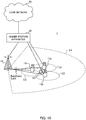
- FIG. 10 is a diagram illustrating an exemplary schematic configuration of a wireless communication system according to an embodiment of the present invention.
- CA Carrier Aggregation
- DC Direct Connectivity
- the wireless communication system 1 may be called, e.g., SUPER 3G, LTE-A (LTE-Advanced), IMT-Advanced, 4G, 5G, or FRA (Future Radio Access).
- the wireless communication system 1 depicted in FIG. 10 includes a radio base station 11 forming a macrocell C1, and radio base stations 12a to 12c forming small cells C2 which are located in the macrocell C1 and more local than the macrocell C1.
- a user terminal 20 resides in the macrocell C1 and each small cell C2.
- the user terminal 20 is connectable to both the radio base station 11 and the radio base stations 12.
- the user terminal 20 is expected to simultaneously use the macrocell C1 and the small cell C2 that use different frequencies by CA or DC.
- the user terminal 20 may employ CA or DC using cells (CCs) (e.g., six or more CCs).
- CCs cells
- a shortened TTI is applicable to UL transmission and/or DL transmission between the user terminal 20 and the radio base station 11/radio base stations 12.
- the user terminal 20 and the radio base station 11 can communicate with each other using a carrier (the existing carrier called, e.g., Legacy carrier) having a narrow bandwidth in a relatively low frequency band (e.g., 2 GHz).
- the user terminal 20 and the radio base stations 12 may communicate with each other using a carrier having a wide bandwidth in a relatively high frequency band (e.g., 3.5 or 5 GHz) or using the same carrier as in communication with the radio base station 11.
- the configuration of the frequency band used by each radio base station is not limited to this.
- Wired connection e.g., an X2 interface or an optical fiber conforming to the CPRI (Common Public Radio Interface)
- wireless connection may be established between the radio base station 11 and the radio base stations 12 (or between the two radio base stations 12).
- the radio base station 11 and each radio base station 12 are respectively connected to a host station device 30 and further connected to a core network 40 via the host station device 30.
- the host station device 30 includes, e.g., an access gateway device, an RNC (Radio Network Controller), and an MME (Mobility Management Entity), the present invention is not limited to this.
- Each radio base station 12 may be connected to the host station device 30 via the radio base station 11.
- the radio base station 11 has a relatively wide coverage and may be called, e.g., a macro base station, an aggregation node, an eNB (eNodeB), or a transmitting/receiving point.
- the radio base station 12 has a local coverage and may be called e.g., a small base station, a micro base station, a pico base station, a femto base station, an HeNB (Home eNodeB), an RRH (Remote Radio Head), or a transmitting/receiving point.
- the radio base stations 11 and 12 will be collectively referred to as radio base stations 10 hereinafter when no distinction is made between them.
- Each user terminal 20 is a terminal that is compatible with various communication schemes such as LTE and LTE-A and may include not only mobile communication terminal but also fixed communication terminal.
- the wireless communication system 1 uses as a radio access scheme, OFDMA (Orthogonal Frequency Division Multiple Access) for downlinks and SC-FDMA (Single-Carrier Frequency Division Multiple Access) for uplinks.
- OFDMA is a multicarrier transmission scheme for communication by dividing a frequency band into narrow frequency bands (subcarriers) and mapping data to each subcarrier.
- SC-FDMA is a single-carrier transmission scheme for dividing the system bandwidth into bands including one or continuous resource block for each terminal, and allowing these terminals to use different bands, thus alleviating inter-terminal interference.
- the uplink and downlink radio access schemes are not limited to these combinations and OFDMA may be used for uplinks.
- the wireless communication system 1 uses, e.g., a PDSCH (Physical Downlink Shared Channel) shared by each user terminal 20, a PBCH (Physical Broadcast Channel), and a downlink L1/L2 control channel as downlink channels.
- the PDSCH is used to transmit, e.g., user data, upper layer control information, and an SIB (System Information Block).
- the PBCH is used to transmit an MIB (Master Information Block).
- the downlink L1/L2 control channel includes, e.g., downlink control channels (a PDCCH (Physical Downlink Control Channel) and an EPDCCH (Enhanced Physical Downlink Control Channel)), a PCFICH (Physical Control Format Indicator Channel), and a PHICH (Physical Hybrid-ARQ Indicator Channel).
- the PDCCH is used to transmit, e.g. DCI (Downlink Control Information) including scheduling information of PDSCHs and PUSCHs.
- the PCFICH is used to transmit the number of OFDM symbols used in the PDCCH.
- the PHICH is used to transmit HARQ delivery acknowledgement information (ACK/NACK) for the PUSCH.
- the EPDCCH is frequency-division-multiplexed with the PDSCH (Physical Downlink Shared Channel) and used to transmit, e.g., DCI, like the PDCCH.
- the wireless communication system 1 uses, e.g., a PUSCH (Physical Uplink Shared Channel) shared by each user terminal 20, a PUCCH (Physical Uplink Control Channel), and a PRACH (Physical Random Access Channel) as uplink channels.
- the PUSCH is used to transmit user data and upper layer control information.
- the PUSCH or the PUCCH is used to transmit UCI (Uplink Control Information) including at least one of, e.g., delivery acknowledgement information (ACK/NACK) and wireless quality information (CQI).
- UCI Uplink Control Information
- ACK/NACK delivery acknowledgement information
- CQI wireless quality information
- the PRACH is used to transmit a random access preamble for establishing connection with a cell.
- FIG. 11 is a diagram illustrating an exemplary configuration of an entire radio base station according to an embodiment of the present invention.
- the radio base station 10 includes transmitting/receiving antennas 101, amplification sections 102, transmitting/receiving sections 103, a baseband signal processing section 104, a call processing section 105, and a transmission line interface 106.
- the transmitting/receiving section 103 includes a transmission unit and a reception unit.
- User data transmitted from the radio base station 10 to the user terminal 20 by a downlink is input from the host station device 30 to the baseband signal processing section 104 via the transmission line interface 106.
- the baseband signal processing section 104 performs transmission processing for the user data, such as PDCP (Packet Data Convergence Protocol) layer processing, user data division and coupling, RLC (Radio Link Control) layer transmission processing such as RLC retransmission control, MAC (Medium Access Control) retransmission control (e.g., HARQ (Hybrid Automatic Repeat reQuest) transmission processing), scheduling, transport format selection, channel encoding, IFFT (Inverse Fast Fourier Transform) processing, and precoding processing, and transfers the user data to the transmitting/receiving sections 103. Transmission processing such as channel encoding and IFFT is also performed for downlink control signals, which are then transferred to the transmitting/receiving sections 103.
- PDCP Packet Data Convergence Protocol
- RLC Radio Link Control
- MAC Medium Access Control
- HARQ Hybrid Automatic Repeat reQuest
- Transmission processing such as channel encoding and IFFT is also performed for downlink control signals, which are then
- the transmitting/receiving section 103 converts a baseband signal precoded and output from the baseband signal processing section 104 for each antenna into a radio frequency band and transmits it.
- the radio frequency signal after frequency conversion by the transmitting/receiving section 103 is amplified by the amplification section 102 and transmitted from the transmitting/receiving antenna 101.
- the transmitting/receiving section (transmission section) 103 can transmit a PDCCH (Physical Downlink Control Channel) (Message 0) for issuing an instruction to transmit a PRACH.
- the transmitting/receiving section (reception section) 103 receives a random access preamble (PRACH) transmitted from the user terminal.
- the transmitting/receiving section (transmission section) 103 can further transmit a response signal (RAR) to a random access preamble transmitted from the user terminal. In doing this, the transmitting/receiving section 103 can perform control to transmit in a second cell, a response signal to a random access preamble received in a first cell.
- the transmitting/receiving section 103 may be implemented as a transmitter/receiver, a transmitting/receiving circuit, or a transmitting/receiving device described on the basis of a common understanding in the technical field according to the present invention.
- the transmitting/receiving section 103 may serve as an integrated transmitting/receiving section or include a transmission section and reception section.
- a radio frequency signal received by the transmitting/receiving antenna 101 is amplified by the amplification section 102.
- the transmitting/receiving section 103 receives the uplink signal amplified by the amplification section 102.
- the transmitting/receiving section 103 performs frequency conversion of the received signal into a baseband signal and outputs it to the baseband signal processing section 104.
- the baseband signal processing section 104 performs FFT (Fast Fourier Transform) processing, IDFT (Inverse Discrete Fourier Transform) processing, error correction decoding, MAC retransmission control reception processing, and RLC layer and PDCP layer reception processing, for user data contained in input uplink signals, and transfers the user data to the host station device 30 via the transmission line interface 106.
- the call processing section 105 performs call processing such as communication channel setup and release, state management of the radio base station 10, and radio resource management.
- the transmission line interface 106 exchanges signals with the host station device 30 via a predetermined interface.
- the transmission line interface 106 may exchange signals with a neighboring radio base station 10 (backhaul signaling) via an interface between base stations (e.g., an X2 interface or an optical fiber conforming to the CPRI (Common Public Radio Interface)).
- a neighboring radio base station 10 backhaul signaling
- base stations e.g., an X2 interface or an optical fiber conforming to the CPRI (Common Public Radio Interface)
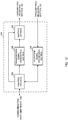
- FIG. 12 is a diagram illustrating an exemplary functional configuration of the radio base station according to the present embodiment.
- FIG. 12 mainly illustrates functional blocks of feature portions in the present embodiment and the radio base station 10 also includes other functional blocks involved in wireless communication.
- the baseband signal processing section 104 includes a control section (scheduler) 301, a transmission signal generation section (generation unit) 302, a mapping section 303, and a received signal processing section 304, as illustrated in FIG. 12 .
- the control section (scheduler) 301 controls scheduling (e.g., resource assignment) of downlink data signals transmitted by PDSCHs and downlink control signals transmitted by PDCCHs and/or EPDCCHs.
- the control section 301 further controls scheduling of, e.g., system information, sync signals, paging information, CRSs (Cell-specific Reference Signals), and CSI-RSs (Channel State Information Reference Signals).
- the control section 301 even controls scheduling of, e.g., uplink reference signals, uplink data signals transmitted by PUSCHs, and uplink control signals transmitted by PUCCHs and/or PUSCHs.
- the control section 301 controls response signal transmission (e.g., the transmission timing) on the basis of a random access preamble transmitted from the user terminal.
- the control section 301 further controls the TTI (Transmission Time Interval) used in DL signal reception and/or UL signal transmission.
- the control section 301 can even control a predetermined interval (reception window) used in response signal transmission, on the basis of the TTI of a cell in which the user terminal transmits a random access preamble or the TTI of a cell in which the user terminal receives a response signal.
- the control section 301 may be implemented as a controller, a control circuit, or a control device described on the basis of a common understanding in the technical field according to the present invention.
- the transmission signal generation section 302 generates a DL signal (including a downlink data signal and a downlink control signal) on the basis of an instruction from the control section 301 and outputs it to the mapping section 303. More specifically, the transmission signal generation section 302 generates a downlink data signal (PDSCH) including user data and outputs it to the mapping section 303. The transmission signal generation section 302 further generates a downlink control signal (PDCCH/EPDCCH) including DCI (UL grant) and outputs it to the mapping section 303. The transmission signal generation section 302 further generates downlink reference signals such as a CRS and a CSI-RS and outputs them to the mapping section 303.
- a DL signal including a downlink data signal and a downlink control signal
- PDSCH downlink data signal
- the transmission signal generation section 302 further generates a downlink control signal (PDCCH/EPDCCH) including DCI (UL grant) and outputs it to the mapping section 303.
- the transmission signal generation section 302
- the transmission signal generation section 302 can even generate an RA-RNTI used for a response signal (e.g., a PDCCH) on the basis of the TTI of a cell in which the user terminal transmits a random access preamble or the TTI of a cell in which the user terminal receives a response signal.
- the transmission signal generation section 302 may be implemented as a signal generator, a signal generation circuit, or a signal generation device described on the basis of a common understanding in the technical field according to the present invention.
- the mapping section 303 maps the DL signal generated by the transmission signal generation section 302 to a predetermined radio resource on the basis of an instruction from the control section 301 and outputs it to the transmitting/receiving section 103.
- the mapping section 303 may be implemented as a mapper, a mapping circuit, or a mapping device described on the basis of a common understanding in the technical field according to the present invention.
- the received signal processing section 304 performs reception processing (e.g., demapping, demodulation, and decoding) for a UL signal (e.g., HARQ-ACK or a PUSCH) transmitted from the user terminal 20.
- reception processing e.g., demapping, demodulation, and decoding
- a UL signal e.g., HARQ-ACK or a PUSCH
- the processing result is output to the control section 301.
- the received signal processing section 304 may be implemented as a set of a signal processor, a signal processing circuit, or a signal processing device and a gauge, a measurement circuit, or a measurement device described on the basis of a common understanding in the technical field according to the present invention.
- FIG. 13 is a diagram illustrating an exemplary configuration of an entire user terminal according to an embodiment of the present invention.
- the user terminal 20 includes transmitting/receiving antennas 201 for MIMO transmission, amplification sections 202, transmitting/receiving sections 203, a baseband signal processing section 204, and an application section 205.
- the transmitting/receiving section 203 may include a transmission unit and a reception unit.
- Radio frequency signals received by the transmitting/receiving antennas 201 are respectively amplified by the amplification sections 202.
- Each transmitting/receiving section 203 receives downlink signals amplified by the amplification sections 202.
- the transmitting/receiving sections 203 perform frequency conversion of the received signals into baseband signals and output them to the baseband signal processing section 204.
- the transmitting/receiving section (reception section) 203 receives DL data signals (e.g., a PDSCH), DL control signals (e.g., HARQ-ACK and a UL grant), and information (HARQ RTT) concerning the HARQ-ACK feedback timing when a shortened TTI is used.
- DL data signals e.g., a PDSCH
- DL control signals e.g., HARQ-ACK and a UL grant
- HARQ RTT information concerning the HARQ-ACK feedback timing when a shortened TTI is used.
- the transmitting/receiving section (reception section) 203 can further receive a PDCCH (Physical Downlink Control Channel) (Message 0) for issuing an instruction to transmit a PRACH.
- PDCCH Physical Downlink Control Channel
- the transmitting/receiving section (transmission section) 203 transmits a random access preamble (PRACH).
- PRACH random access preamble
- the transmitting/receiving section (reception section) 203 can further receive a response signal (RAR) to the random access preamble.
- the transmitting/receiving section 203 may be implemented as a transmitter/receiver, a transmitting/receiving circuit, or a transmitting/receiving device described on the basis of a common understanding in the technical field according to the present invention.
- the baseband signal processing section 204 performs, e.g., FFT processing, error correction decoding, and retransmission control reception processing for an input baseband signal.
- User data on a downlink is transferred to the application section 205.
- the application section 205 performs, e.g., processing associated with layers above a physical layer and a MAC layer. Broadcast information of the data on a downlink is also transferred to the application section 205.
- the baseband signal processing section 204 performs, e.g., retransmission control transmission processing (e.g., HARQ transmission processing), channel encoding, precoding, DFT (Discrete Fourier Transform) processing, and IFFT processing and transfers baseband signals to each transmitting/receiving section 203.
- the transmitting/receiving sections 203 convert the baseband signals output from the baseband signal processing section 204 into radio frequency bands and transmit them.
- the radio frequency signals after frequency conversion by the transmitting/receiving sections 203 are amplified by the amplification sections 202 and transmitted from the transmitting/receiving antennas 201.
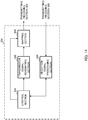
- FIG. 14 is a diagram illustrating an exemplary functional configuration of the user terminal according to the present embodiment.
- FIG. 14 mainly illustrates functional blocks of feature portions in the present embodiment and the user terminal 20 also includes other functional blocks involved in wireless communication.
- the baseband signal processing section 204 of the user terminal 20 includes a control section 401, a transmission signal generation section 402, a mapping section 403, and a received signal processing section 404, as illustrated in FIG. 14 .
- the control section 401 controls communication (e.g., transmission and/or reception) using cells including at least two cells having different TTIs. More specifically, the control section 401 obtains from the received signal processing section 404, a downlink control signal (a signal transmitted by a PDCCH/EPDCCH) and a downlink data signal (a signal transmitted by a PDSCH) transmitted from the radio base station 10.
- the control section 401 controls generation of an uplink control signal (e.g., a delivery acknowledgement signal (HARQ-ACK)) and an uplink data signal on the basis of, e.g., the result of a decision as to whether retransmission control may be performed for the downlink control signal and the downlink data signal. More specifically, the control section 401 can control the transmission signal generation section 402, the mapping section 403, and the received signal processing section 404.
- HARQ-ACK delivery acknowledgement signal
- the control section 401 can control random access preamble transmission and response signal reception so that a second cell receives a response signal to a random access preamble transmitted in a first cell.
- the control section 401 can perform control to, e.g., receive a response signal in a second cell which uses a TTI equal to that of a first cell.
- the control section 401 can perform control not only to transmit a non-contention-based random access preamble for each group formed by cells which use the same TTI, but also to receive a response signal to the non-contention-based random access preamble in a specific cell.
- the control section 401 can control response signal reception on the basis of a first TTI or a subframe number corresponding to the first TTI (see FIG. 6 ).
- the control section 401 can control response signal reception on the basis of a second TTI or a subframe number corresponding to the second TTI (see FIG. 7 ).
- the control section 401 can control response signal reception on the basis of a first TTI or a subframe number corresponding to the first TTI (see FIG. 8 ).
- the control section 401 can control response signal reception on the basis of a second TTI or a subframe number corresponding to the second TTI (see FIG. 9 ).
- the control section 401 can determine an RA-RNTI and/or a predetermined reception interval used in response signal reception, on the basis of the TTI of a first cell which transmits a random access preamble or a second TTI in which a response signal is received.
- the control section 401 may be implemented as a controller, a control circuit, or a control device described on the basis of a common understanding in the technical field according to the present invention.
- the transmission signal generation section 402 generates a UL signal on the basis of an instruction from the control section 401 and outputs it to the mapping section 403.
- the transmission signal generation section 402 generates, e.g., a delivery acknowledgement signal (HARQ-ACK) and an uplink control signal such as channel state information (CSI) on the basis of instructions from the control section 401.
- HARQ-ACK delivery acknowledgement signal
- CSI channel state information
- the transmission signal generation section 402 generates an uplink data signal on the basis of an instruction from the control section 401.
- the transmission signal generation section 402 is instructed to generate an uplink data signal by the control section 401.
- the transmission signal generation section 402 may be implemented as a signal generator, a signal generation circuit, or a signal generation device described on the basis of a common understanding in the technical field according to the present invention.
- the mapping section 403 maps the uplink signal (an uplink control signal and/or uplink data) generated by the transmission signal generation section 402 to a radio resource on the basis of an instruction from the control section 401 and outputs it to the transmitting/receiving section 203.
- the mapping section 403 may be implemented as a mapper, a mapping circuit, or a mapping device described on the basis of a common understanding in the technical field according to the present invention.
- the received signal processing section 404 performs reception processing (e.g., demapping, demodulation, and decoding) for DL signals (e.g., a downlink control signal transmitted from the radio base station and a downlink data signal transmitted by a PDSCH).
- the received signal processing section 404 outputs information received from the radio base station 10 to the control section 401.
- the received signal processing section 404 outputs, e.g., broadcast information, system information, RRC signaling, and DCI to the control section 401.
- the received signal processing section 404 may be implemented as a set of a signal processor, a signal processing circuit, or a signal processing device and a gauge, a measurement circuit, or a measurement device described on the basis of a common understanding in the technical field according to the present invention.
- the received signal processing section 404 may implement a reception unit according to the present invention.
- each functional block may be implemented as one physically coupled device or implemented by at least two physically separate devices connected in a wired or wireless manner.
- radio base station 10 and the user terminal 20 may be implemented using hardware such as an ASIC (Application Specific Integrated Circuit), a PLD (Programmable Logic Device), or an FPGA (Field Programmable Gate Array).
- the radio base station 10 and the user terminal 20 may be implemented as a computer apparatus including a processor (CPU: Central Processing Unit), a communication interface for network connection, a memory, and a computer-readable storage medium holding a program.
- a radio base station, a user terminal, and the like may serve as computers which perform the processes of a wireless communication method according to the present invention.
- the processor, the memory, and the like are connected to each other via buses for information communication.
- Examples of the computer-readable recording medium include storage media such as a flexible disk, a magnetooptical disk, a ROM (Read Only Memory), an EPROM (Erasable Programmable ROM), a CD-ROM (Compact Disc-ROM), a RAM (Random Access Memory), and a hard disk.
- the program may be transmitted from a network via an electrical communication line.
- the radio base station 10 and the user terminal 20 may include input devices such as input keys and output devices such as displays.
- the functional configuration of the radio base station 10 and the user terminal 20 may be implemented as the above-mentioned hardware, as a software module executed by the processor, or as a combination thereof.
- the processor controls the overall user terminal by running the operating system.
- the processor reads out a program, a software module, and data from the storage medium to the memory and performs various processes in accordance with them.
- the program may be any program which causes the computer to execute the respective operations described in the above-described respective embodiments.
- the control section 401 of the user terminal 20 for example, may be implemented as a control program stored in the memory and running on the processor, and the remaining functional blocks may be implemented similarly.
- Software, instructions, and the like may be transmitted and received via transmission media.
- wired technologies such as a coaxial cable, an optical fiber cable, a twisted pair, and a DSL (Digital Subscriber Line) and/or wireless technologies such as infrared, radio, and microwave technologies
- these wired technologies and/or wireless technologies fall within the definition of the transmission media.
- the terms described in this specification and/or the terms involved in understanding this specification may be replaced with terms having the same or similar meanings.
- the channels and/or symbols, for example, may be replaced with signals (signaling).
- the signals may be implemented as messages.
- the CCs Component Carriers
- the CCs may be referred to as carrier frequencies, cells, or the like.
- the information, parameters, and the like described in this specification may be represented by absolute values, values relative to certain values, or other types of equivalent information.
- the radio resources for example, may be indicated by indices.
- Data, instructions, commands, information, signals, bits, symbols, chips, and the like that may be referred to throughout the above description, for example, may be represented by voltages, currents, electromagnetic waves, magnetic fields or particles, optical fields or photons, or any combination thereof.
- the respective aspects/embodiments described in this specification may be used solely, used in combination, or switchably used upon execution.
- the notification of predetermined information e.g., the notification of "X"
- the notification of "X" is not limited to explicit notification, and may be done implicitly (e.g., without notification of the predetermined information).
- the information notification is not limited to the aspects/embodiments described in this specification and may be done using other methods.
- the information notification may be done by, e.g., physical layer signaling (e.g., DCI (Downlink Control Information) and UCI (Uplink Control Information)), upper layer signaling (e.g., RRC (Radio Resource Control) signaling, MAC (Medium Access Control) signaling, and broadcast information (an MIB (Master Information Block) and an SIB (System Information Block))), other signals, or any combination thereof.
- RRC signaling may also be referred to as RRC messages, which may include, e.g., RRC connection setup (RRCConnectionSetup) messages and RRC connection reconfiguration (RRCConnectionReconfiguration) messages.
- LTE Long Term Evolution
- LTE-A Long Term Evolution-Advanced
- SUPER 3G IMT-Advanced
- 4G 5G
- FRA Full Radio Access
- CDMA2000 UMB (Ultra Mobile Broadband)
- UMB Universal Mobile Broadband
- IEEE 802.11 Wi-Fi
- IEEE 802.16 Wi-MAX
- IEEE 802.20 UWB (Ultra-WideBand)
- Bluetooth® Bluetooth®
Applications Claiming Priority (2)
| Application Number | Priority Date | Filing Date | Title |
|---|---|---|---|
| JP2015164189 | 2015-08-21 | ||
| PCT/JP2016/074164 WO2017033837A1 (ja) | 2015-08-21 | 2016-08-19 | ユーザ端末、無線基地局及び無線通信方法 |
Publications (3)
| Publication Number | Publication Date |
|---|---|
| EP3340724A1 EP3340724A1 (en) | 2018-06-27 |
| EP3340724A4 EP3340724A4 (en) | 2019-03-20 |
| EP3340724B1 true EP3340724B1 (en) | 2021-06-30 |
Family
ID=58100196
Family Applications (1)
| Application Number | Title | Priority Date | Filing Date |
|---|---|---|---|
| EP16839184.5A Active EP3340724B1 (en) | 2015-08-21 | 2016-08-19 | User terminal and wireless communication method |
Country Status (6)
| Country | Link |
|---|---|
| US (1) | US11405949B2 (es) |
| EP (1) | EP3340724B1 (es) |
| JP (1) | JP6797807B2 (es) |
| CN (1) | CN107926063B (es) |
| ES (1) | ES2880776T3 (es) |
| WO (1) | WO2017033837A1 (es) |
Families Citing this family (13)
| Publication number | Priority date | Publication date | Assignee | Title |
|---|---|---|---|---|
| BR112017011341A2 (pt) * | 2015-01-14 | 2017-12-26 | Huawei Tech Co Ltd | terminal, estação base, controlador de rede de rádio e método de transmissão de dados em um processo de acesso randômico |
| EP3391604B1 (en) * | 2015-12-18 | 2024-02-21 | Fraunhofer-Gesellschaft zur Förderung der angewandten Forschung e.V. | Data signal transmission in a wireless communication system with reduced end-to-end latency |
| CN107852322A (zh) * | 2016-01-21 | 2018-03-27 | 三菱电机株式会社 | 通信系统、通信装置及通信方法 |
| US20180132242A1 (en) * | 2016-11-04 | 2018-05-10 | Mediatek Inc. | Grouping of serving cells with shortened transmission time intervals |
| WO2018203410A1 (ja) * | 2017-05-02 | 2018-11-08 | 株式会社Nttドコモ | ユーザ装置、基地局及び上り送信タイミング制御方法 |
| JP2020120142A (ja) * | 2017-05-26 | 2020-08-06 | シャープ株式会社 | 端末装置、基地局装置、通信方法、および、集積回路 |
| BR112020022381A2 (pt) * | 2018-05-09 | 2021-02-02 | Ntt Docomo, Inc. | terminal e método de comunicação por um terminal |
| JP7248675B2 (ja) * | 2018-06-28 | 2023-03-29 | 株式会社Nttドコモ | 端末、無線通信方法、基地局及びシステム |
| WO2020003468A1 (ja) * | 2018-06-28 | 2020-01-02 | 株式会社Nttドコモ | ユーザ端末 |
| US20210314049A1 (en) * | 2018-08-09 | 2021-10-07 | Ntt Docomo, Inc. | User terminal and radio communication method |
| EP3927092A4 (en) * | 2019-02-15 | 2022-09-07 | Ntt Docomo, Inc. | USER TERMINAL AND WIRELESS COMMUNICATION METHOD |
| KR20210126615A (ko) * | 2019-02-15 | 2021-10-20 | 가부시키가이샤 엔티티 도코모 | 유저단말 |
| US20220159739A1 (en) * | 2019-03-15 | 2022-05-19 | Ntt Docomo, Inc. | User terminal and radio communication method |
Family Cites Families (36)
| Publication number | Priority date | Publication date | Assignee | Title |
|---|---|---|---|---|
| KR101382748B1 (ko) * | 2008-01-25 | 2014-04-08 | 엘지전자 주식회사 | 무선통신 시스템에서 랜덤 액세스 과정을 수행하는 방법 |
| ES2618152T3 (es) | 2008-02-11 | 2017-06-21 | Nokia Corporation | Respuesta de preámbulo RACH con asignación de enlace ascendente flexible |
| KR100925450B1 (ko) * | 2008-03-03 | 2009-11-06 | 엘지전자 주식회사 | 상향링크 신호의 충돌 해결 방법 |
| GB2461158B (en) * | 2008-06-18 | 2011-03-02 | Lg Electronics Inc | Method for performing random access procedures and terminal therof |
| US8830884B2 (en) * | 2008-08-18 | 2014-09-09 | Qualcomm Incorporated | TTI bundling in a random access procedure |
| EP2553986B1 (en) * | 2010-04-01 | 2016-09-07 | Sun Patent Trust | Transmit power control for physical random access channels |
| EP2265077B1 (en) * | 2009-06-18 | 2012-03-21 | Panasonic Corporation | Enhanced random access procedure for mobile communications |
| KR101528091B1 (ko) * | 2011-04-28 | 2015-06-10 | 엘지전자 주식회사 | 랜덤 액세스 수행 방법 및 장치 |
| US20120300714A1 (en) * | 2011-05-06 | 2012-11-29 | Samsung Electronics Co., Ltd. | Methods and apparatus for random access procedures with carrier aggregation for lte-advanced systems |
| US20140112254A1 (en) * | 2011-06-17 | 2014-04-24 | Telefonaktiebolaget L M Ericsson (Publ) | Methods and nodes for random access |
| US20130010711A1 (en) * | 2011-07-06 | 2013-01-10 | Daniel Larsson | Random Access with Primary and Secondary Component Carrier Communications |
| CN103597886B (zh) | 2011-09-25 | 2018-01-02 | Lg电子株式会社 | 用于控制上行链路传输功率的方法和设备 |
| US20140334448A1 (en) * | 2012-01-17 | 2014-11-13 | Telefonaktiebolaget L M Ericsson (Publ) | Support of Switching TTI Bundling On/Off |
| US8462688B1 (en) * | 2012-01-25 | 2013-06-11 | Ofinno Technologies, Llc | Base station and wireless device radio resource control configuration |
| US8995405B2 (en) * | 2012-01-25 | 2015-03-31 | Ofinno Technologies, Llc | Pathloss reference configuration in a wireless device and base station |
| JP6002245B2 (ja) * | 2012-01-26 | 2016-10-05 | ノキア ソリューションズ アンド ネットワークス オサケユキチュア | 伝送時間間隔長さを決定する方法及び装置 |
| US8995381B2 (en) | 2012-04-16 | 2015-03-31 | Ofinno Technologies, Llc | Power control in a wireless device |
| JP6042127B2 (ja) | 2012-07-25 | 2016-12-14 | 株式会社Nttドコモ | 移動端末装置及び基地局装置 |
| US9131498B2 (en) * | 2012-09-12 | 2015-09-08 | Futurewei Technologies, Inc. | System and method for adaptive transmission time interval (TTI) structure |
| US9204467B2 (en) * | 2012-12-11 | 2015-12-01 | Blackberry Limited | Communicating encoded traffic data |
| WO2014110772A1 (zh) * | 2013-01-17 | 2014-07-24 | 富士通株式会社 | 随机接入方法、装置和系统 |
| HUE038735T2 (hu) * | 2013-03-15 | 2018-11-28 | Qualcomm Inc | Javított véletlen hozzáférési eljárás nyalábformálással LTE rendszerben |
| EP3026830B1 (en) * | 2013-07-26 | 2019-12-04 | LG Electronics Inc. | Method for transmitting signal for mtc and apparatus for same |
| US20170290008A1 (en) * | 2014-09-08 | 2017-10-05 | Interdigital Patent Holdings, Inc. | Systems and Methods of Operating with Different Transmission Time Interval (TTI) Durations |
| US10039134B2 (en) * | 2014-11-14 | 2018-07-31 | Electronics And Telecommunications Research Institute | Method and apparatus for random access in wireless communication system |
| EP3238491A1 (en) * | 2014-12-23 | 2017-11-01 | IDAC Holdings, Inc. | Latency reduction in lte systems |
| US10110363B2 (en) * | 2015-01-29 | 2018-10-23 | Qualcomm Incorporated | Low latency in time division duplexing |
| WO2016133122A1 (ja) * | 2015-02-20 | 2016-08-25 | 株式会社Nttドコモ | ユーザ装置、及びタイマ制御方法 |
| US10455600B2 (en) * | 2015-04-08 | 2019-10-22 | Lg Electronics Inc. | Method for transmitting and receiving data in wireless communication system and apparatus for the same |
| US20160345311A1 (en) * | 2015-05-22 | 2016-11-24 | Qualcomm Incorporated | Techniques for scheduling data communications with shortened time duration |
| CN107615832B (zh) * | 2015-06-11 | 2020-04-21 | 华为技术有限公司 | 一种drx实现方法、配置方法及相关设备 |
| CN107852313B (zh) * | 2015-07-24 | 2021-08-03 | Lg 电子株式会社 | 下行链路控制信息接收方法和用户设备以及下行链路控制信息发送方法和基站 |
| DE112015006779T5 (de) * | 2015-08-06 | 2018-05-24 | Intel IP Corporation | Ausführen missionskritischer Kommunikation an einem Teilnehmergerät (UE) |
| CN107852266B (zh) * | 2015-08-19 | 2020-09-15 | 富士通株式会社 | 支持多种传输时间间隔的随机接入方法、装置以及通信系统 |
| US20180035470A1 (en) * | 2016-07-28 | 2018-02-01 | Asustek Computer Inc. | Method and apparatus for improving msg3 transmission of random access procedure in a wireless communication system |
| EP3277047B1 (en) * | 2016-07-28 | 2021-02-24 | ASUSTek Computer Inc. | Method and apparatus for improving random access procedure in a wireless communication system |
-
2016
- 2016-08-19 CN CN201680048020.3A patent/CN107926063B/zh active Active
- 2016-08-19 JP JP2017536391A patent/JP6797807B2/ja active Active
- 2016-08-19 EP EP16839184.5A patent/EP3340724B1/en active Active
- 2016-08-19 WO PCT/JP2016/074164 patent/WO2017033837A1/ja active Application Filing
- 2016-08-19 ES ES16839184T patent/ES2880776T3/es active Active
- 2016-08-19 US US15/753,730 patent/US11405949B2/en active Active
Non-Patent Citations (1)
| Title |
|---|
| None * |
Also Published As
| Publication number | Publication date |
|---|---|
| EP3340724A1 (en) | 2018-06-27 |
| US11405949B2 (en) | 2022-08-02 |
| JP6797807B2 (ja) | 2020-12-09 |
| US20180242354A1 (en) | 2018-08-23 |
| ES2880776T3 (es) | 2021-11-25 |
| CN107926063B (zh) | 2021-09-21 |
| JPWO2017033837A1 (ja) | 2018-07-19 |
| WO2017033837A1 (ja) | 2017-03-02 |
| CN107926063A (zh) | 2018-04-17 |
| EP3340724A4 (en) | 2019-03-20 |
Similar Documents
| Publication | Publication Date | Title |
|---|---|---|
| EP3340724B1 (en) | User terminal and wireless communication method | |
| US20210195588A1 (en) | Terminal, base station, and radio communication method | |
| US10743304B2 (en) | User terminal, radio base station, and radio communication method | |
| JP6886919B2 (ja) | 端末及び無線通信方法 | |
| JP6961484B2 (ja) | 端末、無線通信方法及びシステム | |
| WO2016121913A1 (ja) | ユーザ端末、無線基地局及び無線通信方法 | |
| US10721615B2 (en) | Terminal and radio communication method for managing a supportable delay using capability information | |
| EP3397012B1 (en) | User terminal, wireless base station, and wireless communication method | |
| US10925089B2 (en) | User terminal, radio base station, and radio communication method | |
| US10602431B2 (en) | User terminal, radio base station, and radio communication method | |
| US20180235010A1 (en) | User terminal, radio base station and radio communication method | |
| WO2017038672A1 (ja) | ユーザ端末、無線基地局及び無線通信方法 |
Legal Events
| Date | Code | Title | Description |
|---|---|---|---|
| STAA | Information on the status of an ep patent application or granted ep patent |
Free format text: STATUS: THE INTERNATIONAL PUBLICATION HAS BEEN MADE |
|
| PUAI | Public reference made under article 153(3) epc to a published international application that has entered the european phase |
Free format text: ORIGINAL CODE: 0009012 |
|
| STAA | Information on the status of an ep patent application or granted ep patent |
Free format text: STATUS: REQUEST FOR EXAMINATION WAS MADE |
|
| 17P | Request for examination filed |
Effective date: 20180306 |
|
| AK | Designated contracting states |
Kind code of ref document: A1 Designated state(s): AL AT BE BG CH CY CZ DE DK EE ES FI FR GB GR HR HU IE IS IT LI LT LU LV MC MK MT NL NO PL PT RO RS SE SI SK SM TR |
|
| AX | Request for extension of the european patent |
Extension state: BA ME |
|
| DAV | Request for validation of the european patent (deleted) | ||
| DAX | Request for extension of the european patent (deleted) | ||
| RIC1 | Information provided on ipc code assigned before grant |
Ipc: H04W 74/08 20090101AFI20170316BHEP Ipc: H04W 76/02 20090101ALI20170316BHEP Ipc: H04W 72/04 20090101ALI20170316BHEP |
|
| A4 | Supplementary search report drawn up and despatched |
Effective date: 20190219 |
|
| RIC1 | Information provided on ipc code assigned before grant |
Ipc: H04W 74/08 20090101AFI20190213BHEP Ipc: H04W 72/04 20090101ALN20190213BHEP |
|
| STAA | Information on the status of an ep patent application or granted ep patent |
Free format text: STATUS: EXAMINATION IS IN PROGRESS |
|
| 17Q | First examination report despatched |
Effective date: 20200226 |
|
| STAA | Information on the status of an ep patent application or granted ep patent |
Free format text: STATUS: EXAMINATION IS IN PROGRESS |
|
| RIC1 | Information provided on ipc code assigned before grant |
Ipc: H04W 74/08 20090101AFI20210201BHEP Ipc: H04W 72/04 20090101ALN20210201BHEP |
|
| GRAP | Despatch of communication of intention to grant a patent |
Free format text: ORIGINAL CODE: EPIDOSNIGR1 |
|
| STAA | Information on the status of an ep patent application or granted ep patent |
Free format text: STATUS: GRANT OF PATENT IS INTENDED |
|
| INTG | Intention to grant announced |
Effective date: 20210315 |
|
| RIC1 | Information provided on ipc code assigned before grant |
Ipc: H04W 72/04 20090101ALN20210302BHEP Ipc: H04W 74/08 20090101AFI20210302BHEP |
|
| GRAS | Grant fee paid |
Free format text: ORIGINAL CODE: EPIDOSNIGR3 |
|
| GRAA | (expected) grant |
Free format text: ORIGINAL CODE: 0009210 |
|
| STAA | Information on the status of an ep patent application or granted ep patent |
Free format text: STATUS: THE PATENT HAS BEEN GRANTED |
|
| REG | Reference to a national code |
Ref country code: DE Ref legal event code: R082 Ref document number: 602016060099 Country of ref document: DE Representative=s name: HOFFMANN - EITLE PATENT- UND RECHTSANWAELTE PA, DE |
|
| AK | Designated contracting states |
Kind code of ref document: B1 Designated state(s): AL AT BE BG CH CY CZ DE DK EE ES FI FR GB GR HR HU IE IS IT LI LT LU LV MC MK MT NL NO PL PT RO RS SE SI SK SM TR |
|
| REG | Reference to a national code |
Ref country code: CH Ref legal event code: EP |
|
| REG | Reference to a national code |
Ref country code: AT Ref legal event code: REF Ref document number: 1407604 Country of ref document: AT Kind code of ref document: T Effective date: 20210715 |
|
| REG | Reference to a national code |
Ref country code: FI Ref legal event code: FGE |
|
| REG | Reference to a national code |
Ref country code: DE Ref legal event code: R096 Ref document number: 602016060099 Country of ref document: DE |
|
| REG | Reference to a national code |
Ref country code: NL Ref legal event code: FP Ref country code: IE Ref legal event code: FG4D |
|
| REG | Reference to a national code |
Ref country code: LT Ref legal event code: MG9D |
|
| PG25 | Lapsed in a contracting state [announced via postgrant information from national office to epo] |
Ref country code: HR Free format text: LAPSE BECAUSE OF FAILURE TO SUBMIT A TRANSLATION OF THE DESCRIPTION OR TO PAY THE FEE WITHIN THE PRESCRIBED TIME-LIMIT Effective date: 20210630 Ref country code: BG Free format text: LAPSE BECAUSE OF FAILURE TO SUBMIT A TRANSLATION OF THE DESCRIPTION OR TO PAY THE FEE WITHIN THE PRESCRIBED TIME-LIMIT Effective date: 20210930 |
|
| REG | Reference to a national code |
Ref country code: ES Ref legal event code: FG2A Ref document number: 2880776 Country of ref document: ES Kind code of ref document: T3 Effective date: 20211125 |
|
| PG25 | Lapsed in a contracting state [announced via postgrant information from national office to epo] |
Ref country code: NO Free format text: LAPSE BECAUSE OF FAILURE TO SUBMIT A TRANSLATION OF THE DESCRIPTION OR TO PAY THE FEE WITHIN THE PRESCRIBED TIME-LIMIT Effective date: 20210930 Ref country code: SE Free format text: LAPSE BECAUSE OF FAILURE TO SUBMIT A TRANSLATION OF THE DESCRIPTION OR TO PAY THE FEE WITHIN THE PRESCRIBED TIME-LIMIT Effective date: 20210630 Ref country code: RS Free format text: LAPSE BECAUSE OF FAILURE TO SUBMIT A TRANSLATION OF THE DESCRIPTION OR TO PAY THE FEE WITHIN THE PRESCRIBED TIME-LIMIT Effective date: 20210630 Ref country code: LV Free format text: LAPSE BECAUSE OF FAILURE TO SUBMIT A TRANSLATION OF THE DESCRIPTION OR TO PAY THE FEE WITHIN THE PRESCRIBED TIME-LIMIT Effective date: 20210630 Ref country code: GR Free format text: LAPSE BECAUSE OF FAILURE TO SUBMIT A TRANSLATION OF THE DESCRIPTION OR TO PAY THE FEE WITHIN THE PRESCRIBED TIME-LIMIT Effective date: 20211001 |
|
| PG25 | Lapsed in a contracting state [announced via postgrant information from national office to epo] |
Ref country code: SK Free format text: LAPSE BECAUSE OF FAILURE TO SUBMIT A TRANSLATION OF THE DESCRIPTION OR TO PAY THE FEE WITHIN THE PRESCRIBED TIME-LIMIT Effective date: 20210630 Ref country code: SM Free format text: LAPSE BECAUSE OF FAILURE TO SUBMIT A TRANSLATION OF THE DESCRIPTION OR TO PAY THE FEE WITHIN THE PRESCRIBED TIME-LIMIT Effective date: 20210630 Ref country code: EE Free format text: LAPSE BECAUSE OF FAILURE TO SUBMIT A TRANSLATION OF THE DESCRIPTION OR TO PAY THE FEE WITHIN THE PRESCRIBED TIME-LIMIT Effective date: 20210630 Ref country code: CZ Free format text: LAPSE BECAUSE OF FAILURE TO SUBMIT A TRANSLATION OF THE DESCRIPTION OR TO PAY THE FEE WITHIN THE PRESCRIBED TIME-LIMIT Effective date: 20210630 Ref country code: PT Free format text: LAPSE BECAUSE OF FAILURE TO SUBMIT A TRANSLATION OF THE DESCRIPTION OR TO PAY THE FEE WITHIN THE PRESCRIBED TIME-LIMIT Effective date: 20211102 Ref country code: RO Free format text: LAPSE BECAUSE OF FAILURE TO SUBMIT A TRANSLATION OF THE DESCRIPTION OR TO PAY THE FEE WITHIN THE PRESCRIBED TIME-LIMIT Effective date: 20210630 |
|
| PG25 | Lapsed in a contracting state [announced via postgrant information from national office to epo] |
Ref country code: PL Free format text: LAPSE BECAUSE OF FAILURE TO SUBMIT A TRANSLATION OF THE DESCRIPTION OR TO PAY THE FEE WITHIN THE PRESCRIBED TIME-LIMIT Effective date: 20210630 |
|
| REG | Reference to a national code |
Ref country code: DE Ref legal event code: R097 Ref document number: 602016060099 Country of ref document: DE Ref country code: CH Ref legal event code: PL |
|
| PG25 | Lapsed in a contracting state [announced via postgrant information from national office to epo] |
Ref country code: MC Free format text: LAPSE BECAUSE OF FAILURE TO SUBMIT A TRANSLATION OF THE DESCRIPTION OR TO PAY THE FEE WITHIN THE PRESCRIBED TIME-LIMIT Effective date: 20210630 |
|
| REG | Reference to a national code |
Ref country code: BE Ref legal event code: MM Effective date: 20210831 |
|
| PG25 | Lapsed in a contracting state [announced via postgrant information from national office to epo] |
Ref country code: LI Free format text: LAPSE BECAUSE OF NON-PAYMENT OF DUE FEES Effective date: 20210831 Ref country code: DK Free format text: LAPSE BECAUSE OF FAILURE TO SUBMIT A TRANSLATION OF THE DESCRIPTION OR TO PAY THE FEE WITHIN THE PRESCRIBED TIME-LIMIT Effective date: 20210630 Ref country code: CH Free format text: LAPSE BECAUSE OF NON-PAYMENT OF DUE FEES Effective date: 20210831 |
|
| PLBE | No opposition filed within time limit |
Free format text: ORIGINAL CODE: 0009261 |
|
| STAA | Information on the status of an ep patent application or granted ep patent |
Free format text: STATUS: NO OPPOSITION FILED WITHIN TIME LIMIT |
|
| PG25 | Lapsed in a contracting state [announced via postgrant information from national office to epo] |
Ref country code: AL Free format text: LAPSE BECAUSE OF FAILURE TO SUBMIT A TRANSLATION OF THE DESCRIPTION OR TO PAY THE FEE WITHIN THE PRESCRIBED TIME-LIMIT Effective date: 20210630 Ref country code: LU Free format text: LAPSE BECAUSE OF NON-PAYMENT OF DUE FEES Effective date: 20210819 |
|
| 26N | No opposition filed |
Effective date: 20220331 |
|
| PG25 | Lapsed in a contracting state [announced via postgrant information from national office to epo] |
Ref country code: FR Free format text: LAPSE BECAUSE OF NON-PAYMENT OF DUE FEES Effective date: 20210830 Ref country code: BE Free format text: LAPSE BECAUSE OF NON-PAYMENT OF DUE FEES Effective date: 20210831 |
|
| REG | Reference to a national code |
Ref country code: AT Ref legal event code: UEP Ref document number: 1407604 Country of ref document: AT Kind code of ref document: T Effective date: 20210630 |
|
| PG25 | Lapsed in a contracting state [announced via postgrant information from national office to epo] |
Ref country code: LT Free format text: LAPSE BECAUSE OF FAILURE TO SUBMIT A TRANSLATION OF THE DESCRIPTION OR TO PAY THE FEE WITHIN THE PRESCRIBED TIME-LIMIT Effective date: 20210630 |
|
| PG25 | Lapsed in a contracting state [announced via postgrant information from national office to epo] |
Ref country code: HU Free format text: LAPSE BECAUSE OF FAILURE TO SUBMIT A TRANSLATION OF THE DESCRIPTION OR TO PAY THE FEE WITHIN THE PRESCRIBED TIME-LIMIT; INVALID AB INITIO Effective date: 20160819 |
|
| P01 | Opt-out of the competence of the unified patent court (upc) registered |
Effective date: 20230509 |
|
| PG25 | Lapsed in a contracting state [announced via postgrant information from national office to epo] |
Ref country code: CY Free format text: LAPSE BECAUSE OF FAILURE TO SUBMIT A TRANSLATION OF THE DESCRIPTION OR TO PAY THE FEE WITHIN THE PRESCRIBED TIME-LIMIT Effective date: 20210630 |
|
| PGFP | Annual fee paid to national office [announced via postgrant information from national office to epo] |
Ref country code: NL Payment date: 20230821 Year of fee payment: 8 |
|
| PGFP | Annual fee paid to national office [announced via postgrant information from national office to epo] |
Ref country code: IT Payment date: 20230825 Year of fee payment: 8 Ref country code: IE Payment date: 20230822 Year of fee payment: 8 Ref country code: GB Payment date: 20230822 Year of fee payment: 8 Ref country code: AT Payment date: 20230822 Year of fee payment: 8 Ref country code: FI Payment date: 20230821 Year of fee payment: 8 |
|
| PGFP | Annual fee paid to national office [announced via postgrant information from national office to epo] |
Ref country code: DE Payment date: 20230821 Year of fee payment: 8 |
|
| PGFP | Annual fee paid to national office [announced via postgrant information from national office to epo] |
Ref country code: ES Payment date: 20231027 Year of fee payment: 8 |
|
| PG25 | Lapsed in a contracting state [announced via postgrant information from national office to epo] |
Ref country code: MK Free format text: LAPSE BECAUSE OF FAILURE TO SUBMIT A TRANSLATION OF THE DESCRIPTION OR TO PAY THE FEE WITHIN THE PRESCRIBED TIME-LIMIT Effective date: 20210630 |