EP3340627A1 - Bilddecodierungsverfahren - Google Patents
Bilddecodierungsverfahren Download PDFInfo
- Publication number
- EP3340627A1 EP3340627A1 EP18152576.7A EP18152576A EP3340627A1 EP 3340627 A1 EP3340627 A1 EP 3340627A1 EP 18152576 A EP18152576 A EP 18152576A EP 3340627 A1 EP3340627 A1 EP 3340627A1
- Authority
- EP
- European Patent Office
- Prior art keywords
- block
- information
- prediction
- motion
- motion information
- Prior art date
- Legal status (The legal status is an assumption and is not a legal conclusion. Google has not performed a legal analysis and makes no representation as to the accuracy of the status listed.)
- Ceased
Links
Images


Classifications
-
- H—ELECTRICITY
- H04—ELECTRIC COMMUNICATION TECHNIQUE
- H04N—PICTORIAL COMMUNICATION, e.g. TELEVISION
- H04N19/00—Methods or arrangements for coding, decoding, compressing or decompressing digital video signals
- H04N19/50—Methods or arrangements for coding, decoding, compressing or decompressing digital video signals using predictive coding
- H04N19/503—Methods or arrangements for coding, decoding, compressing or decompressing digital video signals using predictive coding involving temporal prediction
- H04N19/51—Motion estimation or motion compensation
- H04N19/513—Processing of motion vectors
- H04N19/521—Processing of motion vectors for estimating the reliability of the determined motion vectors or motion vector field, e.g. for smoothing the motion vector field or for correcting motion vectors
-
- H—ELECTRICITY
- H04—ELECTRIC COMMUNICATION TECHNIQUE
- H04N—PICTORIAL COMMUNICATION, e.g. TELEVISION
- H04N19/00—Methods or arrangements for coding, decoding, compressing or decompressing digital video signals
- H04N19/10—Methods or arrangements for coding, decoding, compressing or decompressing digital video signals using adaptive coding
- H04N19/102—Methods or arrangements for coding, decoding, compressing or decompressing digital video signals using adaptive coding characterised by the element, parameter or selection affected or controlled by the adaptive coding
- H04N19/103—Selection of coding mode or of prediction mode
- H04N19/105—Selection of the reference unit for prediction within a chosen coding or prediction mode, e.g. adaptive choice of position and number of pixels used for prediction
-
- H—ELECTRICITY
- H04—ELECTRIC COMMUNICATION TECHNIQUE
- H04N—PICTORIAL COMMUNICATION, e.g. TELEVISION
- H04N19/00—Methods or arrangements for coding, decoding, compressing or decompressing digital video signals
- H04N19/10—Methods or arrangements for coding, decoding, compressing or decompressing digital video signals using adaptive coding
- H04N19/102—Methods or arrangements for coding, decoding, compressing or decompressing digital video signals using adaptive coding characterised by the element, parameter or selection affected or controlled by the adaptive coding
- H04N19/103—Selection of coding mode or of prediction mode
- H04N19/109—Selection of coding mode or of prediction mode among a plurality of temporal predictive coding modes
-
- H—ELECTRICITY
- H04—ELECTRIC COMMUNICATION TECHNIQUE
- H04N—PICTORIAL COMMUNICATION, e.g. TELEVISION
- H04N19/00—Methods or arrangements for coding, decoding, compressing or decompressing digital video signals
- H04N19/10—Methods or arrangements for coding, decoding, compressing or decompressing digital video signals using adaptive coding
- H04N19/102—Methods or arrangements for coding, decoding, compressing or decompressing digital video signals using adaptive coding characterised by the element, parameter or selection affected or controlled by the adaptive coding
- H04N19/119—Adaptive subdivision aspects, e.g. subdivision of a picture into rectangular or non-rectangular coding blocks
-
- H—ELECTRICITY
- H04—ELECTRIC COMMUNICATION TECHNIQUE
- H04N—PICTORIAL COMMUNICATION, e.g. TELEVISION
- H04N19/00—Methods or arrangements for coding, decoding, compressing or decompressing digital video signals
- H04N19/10—Methods or arrangements for coding, decoding, compressing or decompressing digital video signals using adaptive coding
- H04N19/102—Methods or arrangements for coding, decoding, compressing or decompressing digital video signals using adaptive coding characterised by the element, parameter or selection affected or controlled by the adaptive coding
- H04N19/124—Quantisation
-
- H—ELECTRICITY
- H04—ELECTRIC COMMUNICATION TECHNIQUE
- H04N—PICTORIAL COMMUNICATION, e.g. TELEVISION
- H04N19/00—Methods or arrangements for coding, decoding, compressing or decompressing digital video signals
- H04N19/10—Methods or arrangements for coding, decoding, compressing or decompressing digital video signals using adaptive coding
- H04N19/134—Methods or arrangements for coding, decoding, compressing or decompressing digital video signals using adaptive coding characterised by the element, parameter or criterion affecting or controlling the adaptive coding
- H04N19/136—Incoming video signal characteristics or properties
- H04N19/137—Motion inside a coding unit, e.g. average field, frame or block difference
- H04N19/139—Analysis of motion vectors, e.g. their magnitude, direction, variance or reliability
-
- H—ELECTRICITY
- H04—ELECTRIC COMMUNICATION TECHNIQUE
- H04N—PICTORIAL COMMUNICATION, e.g. TELEVISION
- H04N19/00—Methods or arrangements for coding, decoding, compressing or decompressing digital video signals
- H04N19/10—Methods or arrangements for coding, decoding, compressing or decompressing digital video signals using adaptive coding
- H04N19/134—Methods or arrangements for coding, decoding, compressing or decompressing digital video signals using adaptive coding characterised by the element, parameter or criterion affecting or controlling the adaptive coding
- H04N19/146—Data rate or code amount at the encoder output
- H04N19/15—Data rate or code amount at the encoder output by monitoring actual compressed data size at the memory before deciding storage at the transmission buffer
-
- H—ELECTRICITY
- H04—ELECTRIC COMMUNICATION TECHNIQUE
- H04N—PICTORIAL COMMUNICATION, e.g. TELEVISION
- H04N19/00—Methods or arrangements for coding, decoding, compressing or decompressing digital video signals
- H04N19/10—Methods or arrangements for coding, decoding, compressing or decompressing digital video signals using adaptive coding
- H04N19/134—Methods or arrangements for coding, decoding, compressing or decompressing digital video signals using adaptive coding characterised by the element, parameter or criterion affecting or controlling the adaptive coding
- H04N19/157—Assigned coding mode, i.e. the coding mode being predefined or preselected to be further used for selection of another element or parameter
- H04N19/159—Prediction type, e.g. intra-frame, inter-frame or bidirectional frame prediction
-
- H—ELECTRICITY
- H04—ELECTRIC COMMUNICATION TECHNIQUE
- H04N—PICTORIAL COMMUNICATION, e.g. TELEVISION
- H04N19/00—Methods or arrangements for coding, decoding, compressing or decompressing digital video signals
- H04N19/10—Methods or arrangements for coding, decoding, compressing or decompressing digital video signals using adaptive coding
- H04N19/169—Methods or arrangements for coding, decoding, compressing or decompressing digital video signals using adaptive coding characterised by the coding unit, i.e. the structural portion or semantic portion of the video signal being the object or the subject of the adaptive coding
- H04N19/17—Methods or arrangements for coding, decoding, compressing or decompressing digital video signals using adaptive coding characterised by the coding unit, i.e. the structural portion or semantic portion of the video signal being the object or the subject of the adaptive coding the unit being an image region, e.g. an object
- H04N19/176—Methods or arrangements for coding, decoding, compressing or decompressing digital video signals using adaptive coding characterised by the coding unit, i.e. the structural portion or semantic portion of the video signal being the object or the subject of the adaptive coding the unit being an image region, e.g. an object the region being a block, e.g. a macroblock
-
- H—ELECTRICITY
- H04—ELECTRIC COMMUNICATION TECHNIQUE
- H04N—PICTORIAL COMMUNICATION, e.g. TELEVISION
- H04N19/00—Methods or arrangements for coding, decoding, compressing or decompressing digital video signals
- H04N19/10—Methods or arrangements for coding, decoding, compressing or decompressing digital video signals using adaptive coding
- H04N19/169—Methods or arrangements for coding, decoding, compressing or decompressing digital video signals using adaptive coding characterised by the coding unit, i.e. the structural portion or semantic portion of the video signal being the object or the subject of the adaptive coding
- H04N19/182—Methods or arrangements for coding, decoding, compressing or decompressing digital video signals using adaptive coding characterised by the coding unit, i.e. the structural portion or semantic portion of the video signal being the object or the subject of the adaptive coding the unit being a pixel
-
- H—ELECTRICITY
- H04—ELECTRIC COMMUNICATION TECHNIQUE
- H04N—PICTORIAL COMMUNICATION, e.g. TELEVISION
- H04N19/00—Methods or arrangements for coding, decoding, compressing or decompressing digital video signals
- H04N19/50—Methods or arrangements for coding, decoding, compressing or decompressing digital video signals using predictive coding
- H04N19/503—Methods or arrangements for coding, decoding, compressing or decompressing digital video signals using predictive coding involving temporal prediction
- H04N19/51—Motion estimation or motion compensation
- H04N19/513—Processing of motion vectors
- H04N19/517—Processing of motion vectors by encoding
- H04N19/52—Processing of motion vectors by encoding by predictive encoding
-
- H—ELECTRICITY
- H04—ELECTRIC COMMUNICATION TECHNIQUE
- H04N—PICTORIAL COMMUNICATION, e.g. TELEVISION
- H04N19/00—Methods or arrangements for coding, decoding, compressing or decompressing digital video signals
- H04N19/60—Methods or arrangements for coding, decoding, compressing or decompressing digital video signals using transform coding
- H04N19/61—Methods or arrangements for coding, decoding, compressing or decompressing digital video signals using transform coding in combination with predictive coding
-
- H—ELECTRICITY
- H04—ELECTRIC COMMUNICATION TECHNIQUE
- H04N—PICTORIAL COMMUNICATION, e.g. TELEVISION
- H04N19/00—Methods or arrangements for coding, decoding, compressing or decompressing digital video signals
- H04N19/70—Methods or arrangements for coding, decoding, compressing or decompressing digital video signals characterised by syntax aspects related to video coding, e.g. related to compression standards
-
- H—ELECTRICITY
- H04—ELECTRIC COMMUNICATION TECHNIQUE
- H04N—PICTORIAL COMMUNICATION, e.g. TELEVISION
- H04N19/00—Methods or arrangements for coding, decoding, compressing or decompressing digital video signals
- H04N19/90—Methods or arrangements for coding, decoding, compressing or decompressing digital video signals using coding techniques not provided for in groups H04N19/10-H04N19/85, e.g. fractals
- H04N19/96—Tree coding, e.g. quad-tree coding
Definitions
- Embodiments described herein relate generally to an image encoding method and an image decoding method.
- H.264 a moving image coding method in which a encoding efficiency is largely improved is recommended as ITU-T Rec. H.264 and ISO/IEC 14496-10 (hereinafter referred to as H.264) by ITU-T and ISO/IEC.
- prediction processing, transform processing, and entropy coding processing are performed in rectangular block units (for example, a 16-by-16 pixel block unit and an 8-by-8 pixel block unit).
- motion compensation is performed to a rectangular block of an encoding target (hereinafter referred to as an encoding target block).
- a prediction in a temporal direction is performed by referring to an already-encoded frame (hereinafter referred to as a reference frame).
- the motion compensation it is necessary to encode and transmit motion information including a motion vector to a decoding side.
- the motion vector is information on a spatial shift between the encoding target block and a block referred to in the reference frame.
- the motion compensation is performed using a plurality of reference frames, it is necessary to encode a reference frame number in addition to the motion information. Therefore, an code amount related to the motion information and the reference frame number may increase.
- a direct mode in which the motion vector to be allocated to the encoding target block is derived from the motion vectors allocated to the already-encoded blocks and the predicted image is generated based on the derived motion vector, is cited as an example of a method for evaluating the motion vector in motion compensation prediction (see JP-B 4020789 and United States Patent NO. 7233621 ).
- the direct mode because the motion vector is not encoded, the code amount of the motion information can be reduced.
- the direct mode is adopted in H.264/AVC.
- the motion vector of the encoding target block is predicted and generated by a fixed method for calculating the motion vector from a median of the motion vectors of the already-encoded blocks adjacent to the encoding target block. Therefore, the motion vector calculation has a low degree of freedom.
- a method for selecting one already-encoded block from the already-encoded blocks to allocate the motion vector to the encoding target block has been proposed in order to enhance the degree of freedom of the motion vector calculation.
- an object of the invention is to provide image encoding and image decoding methods having a high encoding efficiency.
- an image encoding method includes a first step of selecting a motion reference block from an already-encoded pixel block to which an inter prediction is applied, the motion reference block including a first motion reference block that is spatially adjacent to an encoding target block in an upward direction and a second motion reference block that is spatially adjacent to the encoding target block in a left direction.
- the image encoding method includes a second step of selecting one or more available blocks from the motion reference block, the available blocks each including a candidate of motion information applied to the encoding target block and different motion information.
- the image encoding method includes a third step of selecting a selection block from the available blocks.
- the image encoding method includes a fourth step of generating a predicted image of the encoding target block using motion information of the selection block.
- the image encoding method includes a fifth step of encoding a prediction error between the predicted image and an original image.
- the image encoding method includes a sixth step of encoding selection information specifying the selection block by referring to a code table decided according to a number of the available blocks.
- an image decoding method includes a first step of selecting a motion reference block from an already-decoded pixel block to which an inter prediction is applied, the motion reference block including a first motion reference block that is spatially adjacent to an decoding target block in an upward direction and a second motion reference block that is spatially adjacent to the decoding target block in a left direction.
- the image decoding method includes a second step of selecting one or more available blocks from the motion reference block, the available blocks each including a candidate of motion information applied to the decoding target block and different motion information.
- the image decoding method includes a third step of selecting a selection block from the available blocks.
- the image decoding method includes a fourth step of generating a predicted image of the decoding target block using motion information of the selection block.
- the image decoding method includes a fifth step of decoding a prediction error between the predicted image and an original image.
- the image decoding method includes a sixth step of decoding selection information specifying the selection block by referring to a code table decided according to a number of the available blocks.
- FIG. 1 schematically illustrates an image encoding apparatus according to a first embodiment.
- the image encoding apparatus includes an image encoder 100, an encoding controller 150, and an output buffer 110.
- the image encoding apparatus in FIG. 1 may be realized by hardware, such as an LSI chip, or realized by causing a computer to execute an image encoding program.
- an input image signal 10 of a moving image or a still image is input to the image encoder 100 in a unit of each of the pixel blocks into which an original image is divided.
- the image encoder 100 performs compression encoding of the input image signal 10 to generate encoded data 14.
- the generated encoded data 14 is temporarily stored in the output buffer 110, and transmitted to a storage system (a storage media, not illustrated) or a transmission system (a communication line, not illustrated) at an output timing managed by the encoding controller 150.
- the encoding controller 150 controls the entire encoding processing of the image encoder 100, namely, feedback control of a generated code amount, quantization control, prediction mode control, and entropy encoding control. Specifically, the encoding controller 150 provides encoding control information 50 to the image encoder 100, and properly receives feedback information 51 from the image encoder 100.
- the encoding control information 50 includes prediction information, motion information 18, and quantization parameter information.
- the prediction information includes prediction mode information and block size information.
- the motion information 18 includes a motion vector, a reference frame number, and a prediction direction (a unidirectional prediction and a bidirectional prediction).
- the quantization parameter information includes a quantization parameter, such as a quantization width (or a quantization step size), and a quantization matrix.
- the feedback information 51 includes the generated code amount by the image encoder 100. For example, the feedback information 51 is used to decide the quantization parameter.
- the image encoder 100 encodes the input image signal 10 in pixel block units (for example, a coding tree unit, a macroblock, a sub-block, and one pixel). Therefore, the input image signal 10 is sequentially input to the image coding unit 100 in units of pixel blocks into which the original image is divided.
- a processing unit for encoding is the coding tree unit, and the coding tree unit that is of an encoding target is referred to as an encoding target block.
- the processing unit for encoding is not limited to the coding tree unit, but the macroblock, the sub-block, or one pixel may be used as the processing unit for encoding.
- the coding tree unit can be replaced with the macroblock, the sub-block, or one pixel.
- an image frame including the encoding target block, namely the image frame of the encoding target is referred to as an encoding target frame.
- the coding tree unit is a 128-by-128-pixel block in FIG. 2A , a 64-by-64-pixel block in FIG. 2B , a 32-by-32-pixel block in FIG. 2C , a 16-by-16-pixel block in FIG. 2D , an 8-by-8-pixel block in FIG. 2E , and a 4-by-4-pixel block in FIG. 2F .
- the coding tree unit is not limited to the pixel blocks in FIGS. 2A to 2F , and the coding tree unit may be a pixel block larger than the 128-by-128-pixel block or the pixel block smaller than the 4-by-4-pixel block.
- a shape of the coding tree unit is not limited to a square in FIGS. 2A to 2F , and the coding tree unit may be set to any shape, such as a rectangular pixel block (an N-by-M-pixel block) of a 32-by-16-pixel block.
- FIGS. 3A to 3D illustrate specific examples of the coding tree unit.
- FIG. 3A illustrates a 64-by-64-pixel coding tree unit CU 0 .
- the size of the coding tree unit is defined as 2N ⁇ 2N pixels.
- N indicates the size of the coding tree unit that is of a reference.
- N 32 in the coding tree unit CU 0 in FIG. 3A .
- the coding tree unit CU 0 has a quadtree structure, and the coding tree unit CU 0 can be divided into four pixel blocks each of which has N ⁇ N pixels. In the case that the coding tree unit is divided, an index is provided to the four pixel blocks in the Z-scan order.
- FIG. 3B illustrates an example of quadtree segmentation of the 64-by-64-pixel block in FIG. 3A . Numbers of 0 to 3 in FIG. 3B indicate the order of the Z-scan.
- the quadtree segmentation of the pixel block obtained by the quadtree segmentation can recursively be performed. In the present embodiment, a depth of the segmentation is defined by Depth.
- the coding tree unit CU 1 is divided into four pixel blocks each of which has 16 ⁇ 16 pixels as illustrated in FIG. 3D .
- the size of coding tree unit decreases with increasing depth Depth of the division.
- the largest unit of the coding tree unit is referred to as a large coding tree unit, and the input image signal 10 is sequentially input and encoded in this unit.
- the quadtree segmentation of the coding tree unit is recursively performed.
- Each of the large coding tree unit and the minimum coding tree unit may have any size as long as the size of the large coding tree unit is greater than or equal to that of the minimum coding tree unit.
- the sizes of the large coding tree unit and the minimum coding tree unit may be changed in each sequence, picture, slice, and region in the slice.
- the sizes of the large coding tree unit and the minimum coding tree unit may adaptively be switched according to slice types, such as an I-slice, a B-slice, and a P-slice.
- the encoding processing may be performed to each coding tree unit in the encoding target frame in any order.
- the encoding processing is performed from the coding tree unit of the upper left of the encoding target frame toward the coding tree unit of the lower right, namely, in the raster-scan order.
- the image encoder 100 of the present embodiment can perform prediction processing in a pixel block unit called a prediction unit.
- the prediction unit is the same pixel block as the coding tree unit or each of the pixel blocks into which the coding tree unit is divided.
- the prediction unit may be a pixel block having a shape different from that of the coding tree unit.
- the prediction unit may be a pixel block having a size larger than that of the coding tree unit.
- FIGS. 5A to 5I illustrate specific examples of the prediction unit.
- FIG. 5A illustrates an example in which the size of the prediction unit is equal to that of the coding tree unit. In this case, one prediction unit PU0 exists in the coding tree unit.
- FIGS. 5B to 5I illustrate examples in each of which a plurality of prediction units exist in the coding tree unit.
- two prediction units PU 0 and PU 1 exist in the coding tree unit.
- the prediction units PU 0 and PU 1 are two pixel blocks into which the coding tree unit is vertically divided.
- the prediction units PU 0 and PU 1 are two pixel blocks into which the coding tree unit is horizontally divided.
- FIG. 5D illustrates an example in which the prediction units are the four pixel blocks into which the coding tree unit is divided.
- the block sizes of the prediction units existing in the coding tree unit may be different from each other as illustrated in FIGS. 5E, 5F , and 5G .
- the prediction unit may be a pixel block that is obtained by dividing the coding tree unit into line segments or curves, such as arcs.
- the image encoder 100 in FIG. 1 will be described in detail.
- the image encoder 100 in FIG. 1 includes a predictor 101, a subtractor 102, a transform/quantization module 103, a variable length encoder 104, an inverse-quantization/inverse-transform module 105, an adder 106, a frame memory 107, a motion information memory 108, and an available-block acquiring module 109.
- the input image signal 10 is provided to the predictor 101 and the subtractor 102.
- the subtractor 102 receives the input image signal 10, and receives a predicted image signal 11 from the predictor 101.
- the subtractor 102 calculates a difference between the input image signal 10 and the predicted image signal 11 to generate a prediction error image signal 12.
- the transform/quantization module 103 receives the prediction error image signal 12 from the subtractor 102, and performs transform processing to the received prediction error image signal 12 to generate a transform coefficient.
- the transform processing is an orthogonal transform, such as a discrete cosine transform (DCT).
- the transform/quantization module 103 may generate the transform coefficient using techniques, such as a wavelet transform and an independent component analysis, instead of the discrete cosine transform. Then the transform/quantization module 103 quantizes the generated transform coefficient based on the quantization parameter provided by the encoding controller 150.
- the quantized transform coefficient (also called transform coefficient information) 13 is transmitted to the variable length encoder 104 and the inverse-quantization/inverse-transform module 105.
- the inverse-quantization/inverse-transform module 105 inversely quantizes the quantized transform coefficient 13 based on the quantization parameter provided by the encoding controller 150, namely, the quantization parameter that is identical to that of the transform/quantization module 103. Then the inverse-quantization/inverse-transform module 105 performs an inverse transform to the inversely-quantized transform coefficient to generate a decoded prediction error signal 15. The inverse transform processing performed by the inverse-quantization/inverse-transform module 105 is matched with the inverse transform processing of the transform processing performed by the transform/quantization module 103.
- an inverse discrete cosine transform is the inverse transform processing performed by the inverse-quantization/inverse-transform module 105.
- IDCT inverse discrete cosine transform
- wavelet transform is the transform processing performed by the transform/quantization module 103
- inverse wavelet transform is the inverse transform processing performed by the inverse-quantization/inverse-transform module 105.
- the adder 106 receives the decoded prediction error signal 15 from the inverse-quantization/inverse-transform module 105, and receives the predicted image signal 11 from the predictor 101.
- the adder 106 adds the decoded prediction error signal 15 and the predicted image signal 11 to generate a locally-decoded image signal 16.
- the generated locally-decoded image signal 16 is stored as a reference image signal 17 in the frame memory 107.
- the reference image signal 17 stored in the frame memory 107 is read and referred to by the predictor 101 in encoding the encoding target block.
- the predictor 101 receives the reference image signal 17 from the frame memory 107, and receives the available block information 20 from the available-block acquiring module 109.
- the predictor 101 receives reference motion information 19 from the motion information memory 108.
- the predictor 101 generates the predicted image signal 11, the motion information 18, selection block information 21, and prediction switching information 22 based on the reference image signal 17, the reference motion information 19, and the available block information 20.
- the predicted image signal 11 is transmitted to the subtractor 102 and the adder 106.
- the motion information 18 is transmitted to the variable length encoder 104, and stored in the motion information memory 108 for the purpose of the prediction processing performed to the subsequent encoding target block.
- the selection block information 21 and the prediction switching information 22 are transmitted to the variable length encoder 104.
- the predictor 101 is described in detail later.
- FIG. 6A illustrates an example of the motion information memory 108. As illustrated in FIG. 6A , the pieces of reference motion information 19 are retained in frames in the motion information memory 108, and form a motion information frame 25. FIG. 6A also illustrates an example of the motion information frame 25 of the encoding target frame, wherein the pieces of motion information 18 of the already-encoded coding tree unit and the prediction unit are stored as the pieces of reference motion information 19.
- FIG. 6B illustrates another example of the motion information memory 108.
- FIG. 6B only the pieces of reference motion information 19 of the pixel blocks adjacent to the encoding target block are retained.
- a capacity of memory can be reduced compared with the case that the pieces of reference motion information 19 of all the already-encoded pixel blocks are retained as illustrated in FIG. 6A .
- the pieces of reference motion information 19 are retained in the motion information frame 25 in a unit of a predetermined region (for example, in a unit of 4-by-4-pixel block).
- the reference motion information 19 includes information indicating whether the region is encoded by an inter prediction or an intra prediction.
- the motion information on the coding tree unit (or the prediction unit) is retained as the reference motion information 19 even in the case that the inter prediction of the coding tree unit (or the prediction unit) is performed without encoding a value of the motion vector using the motion information predicted from the already-encoded region.
- the motion information memory 108 is not limited to the example in which the pieces of reference motion information 19 are retained in a unit of 4-by-4-pixel block, and the pieces of reference motion information 19 may be retained in another pixel block unit.
- the unit of the pixel block in which the reference motion information 19 is retained may be one pixel or a 2-by-2-pixel block.
- the shape of the pixel block in which the reference motion information 19 is retained is not limited to the square, and the pixel block may have any shape.
- the variable length encoder 104 in FIG. 1 receives the transform coefficient information 13 from the transform/quantization module 103, receives the motion information 18, the selection block information 21, and the prediction switching information 22 from the predictor 101, receives the prediction information and encoding parameters, such as the quantization parameter, from the encoding controller 150, and receives the available block information 20 from the available-block acquiring module 109.
- the variable length encoder 104 performs entropy encoding (for example, fixed length coding, Huffman coding, and arithmetic coding) to the transform coefficient information 13, the motion information 18, the selection block information 21, the prediction switching information 22, and the encoding parameters, and multiplexes them to generate the encoded data 14.
- the variable length encoder 104 includes a parameter encoder 701, a transform coefficient encoder 702, a selection block information/prediction switching information encoder 703, a motion information encoder 704, and a multiplexer 705.
- the parameter encoder 701 encodes the encoding parameters received from the encoding controller 150, and generates encoded data 14A.
- the transform coefficient encoder 702 encodes the transform coefficient information 13 received from the transform/quantization module 103, and generates encoded data 14B.
- the selection block information/prediction switching information encoder 703 encodes the selection block information 21 and the prediction switching information 22, which are received from the predictor 101, and generates encoded data 14C.
- the motion information encoder 704 encodes the motion information 18 received from the predictor 101, and generates encoded data 14D.
- the multiplexer 705 multiplexes the pieces of encoded data 14A, 14B, 14C, and 14D to generate the encoded data 14.
- the generated encoded data 14 includes all parameters, such as information on the transform coefficient and information on the quantization, which are necessary for the decoding.
- the encoded data 14 is temporarily stored in the output buffer 110 and then transmitted to the storage system (not illustrated) or the transmission system (not illustrated).
- the motion information encoder 704 is not used when a first predictor 1001 (illustrated in FIG. 10 ) performs the prediction processing.
- the selection block information/prediction switching information encoder 703 is not used when a second predictor 1002 (illustrated in FIG. 10 ) performs the prediction processing.
- a plurality of prediction modes are prepared in the image encoder 100 in FIG. 1 , and the prediction modes differ from each other in a method for generating the predicted image signal 11 and a motion compensation block size.
- the method by which the predictor 101 generates the predicted image signal 11 is divided into the intra prediction (also called intra-frame prediction) that generates a prediction image using the reference image signal 17 of the encoding target frame (or a field) and the inter prediction (also called inter-frame prediction) that generates a prediction image using the reference image signal 17 of at least one already-encoded reference frame (or a reference field).
- the predictor 101 selectively switches between the intra prediction and the inter prediction to generate the predicted image signal 11 of the encoding target block.
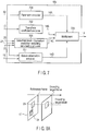
- FIG. 8A illustrates an example of the inter prediction.
- the inter prediction is performed in prediction units, and different pieces of motion information 18 can be possessed in prediction units.
- the predicted image signal 11 is generated using the reference image signal 17 of a block 24 in the position that is spatially shifted from a block 23 according to the motion vector included in the motion information 18, wherein the block 23 is of a pixel block in the already-encoded reference frame (for example, the already-encoded frame in one frame earlier) and is located in the same position as the prediction unit of the encoding target. That is, the reference image signal 17 of the block 24 in the reference frame, which is specified by the position (a coordinate) of the encoding target block and the motion vector included in the motion information 18, is used in generating the predicted image signal 11.
- interpolation processing can be performed to a luminance signal up to the 1/4 pixel accuracy.
- an information amount of the motion information 18 is quadruple of that of the integer pixel accuracy.
- the interpolation processing can be performed using arbitrary filtering instead of the filtering defined in H.264.
- the inter prediction is not limited to the example in which the reference frame in the preceding frame is used as illustrated in FIG. 8A , and any already-encoded reference frame may be used as illustrated in FIG. 8B .
- the reference image signals 17 of the multiple reference frames having different temporal positions are retained, the information indicating where the predicted image signal 11 is generated from the reference image signal 17 in the temporal position is expressed by the reference frame number.
- the reference frame number is included in the motion information 18.
- the reference frame number can be changed in region units (such as picture units and block units). That is, a different reference frame can be used in each prediction unit. For example, in the case that the reference frame in the first preceding already-encoded frame is used in the prediction, the reference frame number in this region is set to 0.
- the reference frame number in this region is set to 1.
- the reference frame number is always set to 0.
- the size suitable for the encoding target block can be selected from the previously-prepared sizes of the prediction units. For example, as illustrated in FIGS. 5A to 5I , the motion compensation can be performed in each prediction unit that is obtained by dividing the coding tree unit.
- the motion information 18 on the already-encoded pixel block (for example, 4-by-4-pixel block) in the encoding target frame used for the inter prediction is retained as the reference motion information 19, so that the shape, the motion vector, and the reference frame number of the optimum motion compensation block can be used according to a local property of the input image signal 10.
- the coding tree unit and the prediction unit can arbitrarily be combined.
- the 16-by-16-pixel block can hierarchically be used from the 64-by-64-pixel block by further dividing the four coding tree units (32-by-32-pixel blocks), into which the 64-by-64-pixel block is divided, into four.
- the 8-by-8-pixel block can hierarchically be used from the 64-by-64-pixel block.
- the prediction unit is one in which the coding tree unit is divided into four
- hierarchical motion compensation processing from the 64-by-64-pixel block to the 4-by-4-pixel block can be performed.
- the motion reference block is selected from the encoding target frame and the already-encoded block in the reference frame according to the method decided by both the image encoding apparatus in FIG. 1 and an image decoding apparatus.
- an already-encoded block A that is adjacent to an encoding target block X in the left direction and an already-encoded block B that is adjacent to the encoding target block X in the upward direction are selected as the motion reference block from the already-encoded blocks of the encoding target frame.
- Pixels a and b which are specified by relative positions in FIG. 9B from the upper-left pixel in the encoding target block, belong to the blocks A and B, respectively.
- the block A includes the pixel a that is adjacent to the upper-left pixel in the encoding target block in the left direction
- the block B includes the pixel b that is adjacent to the upper-left pixel in the encoding target block in the upward direction.
- Each available block is selected from the motion reference blocks by the available-block acquiring module 109.
- the available block is a block to which the inter prediction is applied in the motion reference blocks.
- one of the motion reference blocks is selected as the available block. Therefore, in the case the available blocks are selected, the available blocks have different motion vectors.
- the available-block acquiring module 109 When selecting the available block from the motion reference blocks, the available-block acquiring module 109 outputs the available block information 20 indicating the selected available block. For example, as illustrated in FIG. 9A , in the case that the motion reference blocks are the blocks A and B that are adjacent to the encoding target block, the available-block acquiring module 109 refers to the pieces of reference motion information 19 on the blocks A and B to determine whether the blocks A and B are the available blocks, and the available-block acquiring module 109 outputs the available block information 20 indicating a determination result.
- the number of motion reference blocks is not limited to two in FIG. 9A , and the number of motion reference blocks may be three or more.
- already-encoded adjacent blocks C and D in FIG. 9C are used as the motion reference block.
- FIG. 9D illustrates an example of the relative positions of the pixels a, b, c, and d included in the blocks A, B, C, and D in FIG. 9D with respect to the upper-left pixel in the encoding target block X.
- the encoding target block is illustrated as the N-by-N-pixel block.
- the block C includes the pixel c in the position that is shifted from the upper-left pixel in the encoding target block X by N pixels in the right direction and by one pixel in the upward direction
- the block D includes the pixel d in the position that is shifted from the upper-left pixel in the encoding target block X by one pixel in the left direction and by one pixel in the upward direction.
- FIG. 9A the example in which the blocks A and B adjacent to the encoding target block are selected as the motion reference block is described.
- the predictor 101 of the first embodiment will be described in detail below.
- the predictor 101 includes the first predictor 1001, the second predictor 1002, and a prediction method selector switch 1003.
- the predictor 101 selectively switches between the first predictor 1001 and the second predictor 1002 to generate the predicted image signal 11.
- the first predictor 1001 generates a predicted image signal 11A according to a first prediction method. Specifically, the first predictor 1001 selects, as a selection block, the block, which is used for the prediction, from the available blocks indicated by the available block information 20, and generates the predicted image signal 11A using reference motion information 19 on the selection block. The first predictor 1001 outputs information on the selection block (selection block information) 21.
- the selection block information (also referred to as selection information) 21 includes information on the number of available blocks and information identifying the selection block.
- the selection block information/prediction switching information encoder 703 encodes the selection block information 21 using a code table that is previously decided according to the number of available blocks indicated by the available block information 20.
- FIG. 11 illustrates the first predictor 1001 in detail.
- the first predictor 1001 includes a motion information selector 1101 and a motion compensator 1104.
- the available block information 20, the reference motion information 19, and the reference image signal 17 are input to the first predictor 1001, and the first predictor 1001 outputs the predicted image signal 11A, the motion information 18, and the selection block information 21.
- the motion information selector 1101 includes a motion information acquiring module 1102 and a motion information selector switch 1103.
- the available block information 20 and the reference motion information 19 on the motion reference block are provided to the motion information acquiring module 1102.
- the motion information acquiring module 1102 generates motion information 18A and motion information 18B.
- the motion information 18A includes the reference motion information 19 on the motion reference block A and the available block information 20, and the motion information 18B includes the reference motion information 19 on the motion reference block B and the available block information 20.
- the motion reference block A is spatially adjacent to the encoding target block in the left direction, namely, adjacent to the encoding target block in the left direction in the encoding target frame.
- the motion reference block B is spatially adjacent to the encoding target block in the upward direction, namely, adjacent to the encoding target block in the upward direction in the encoding target frame.
- the motion information acquiring module 1102 outputs as many pieces of motion information as available blocks.
- the two motion reference blocks A and B are set, as in the first embodiment, the two pieces of motion information are output at most.
- the pieces of motion information 18A and 18B are output when both the motion reference blocks A and B are selected as the available block, and the motion information is not output when both the motion reference blocks A and B are not selected as the available block.
- the four motion reference blocks are set as illustrated in FIG. 9C , the four pieces of motion information are output at most according to the number of available blocks.
- the motion information selector switch 1103 selects one selection block from the available blocks to transmit one of the pieces of motion information 18A and 18B as the motion information 18 to the motion compensator 1104.
- the motion information selector switch 1103 outputs the selection block information 21 indicating which available block is selected as the selection block.
- the motion information selector switch 1103 selects the available block as the selection block such that an encoding cost derived from a cost equation indicated by the following mathematical formula (1) is minimized.
- J D + ⁇ ⁇ R
- J indicates the encoding cost
- D indicates an encoding strain expressing a sum of squared difference between the input image signal 10 and the reference image signal 17.
- R indicates a code amount estimated by temporary encoding and ⁇ indicates a Lagrange undetermined coefficient defined by the quantization width.
- the encoding cost J may be calculated using only the code amount R or the encoding strain D instead of the mathematical formula (1), and a cost function of the mathematical formula (1) may be produced using a value in which the code amount R or the encoding strain D is approximated.
- the encoding strain D is not limited to the sum of squared difference, and the encoding strain D may be a sum of absolute difference (SAD). Only the code amount related to the motion information may be used as the code amount R.
- the selection block is not limited to the example in which the available block minimizing the encoding cost is selected as the selection block, and one available block having a value within a range where the encoding cost is at least the minimum may be selected as the selection block.
- the motion compensator 1104 derives the position of the pixel block, in which the reference image signal 17 is taken out as the predicted image signal, based on the reference motion information (or a reference motion information group) on the selection block selected by the motion information selector 1101.
- the motion compensator 1104 divides the pixel block taken out as the predicted image signal by the reference image signal 17 into small pixel blocks (for example, 4-by-4-pixel blocks), and applies the corresponding reference motion information to each small pixel block to acquire the predicted image signal 11A from the reference image signal 17. For example, as illustrated in FIG. 8A , the position of the block in which the predicted image signal 11A is acquired is shifted from the small pixel block to the spatial direction according to the motion vector included in the reference motion information 19.
- the motion compensator 1104 generates the predicted image signal 11A using the reference motion information (one of pieces of reference motion information 19A and 19B) from the motion information selector 1101 and the reference image signal 17 from the frame memory 107.
- the first predictor 1001 does not perform the prediction processing, and only the second predictor 1002 performs the prediction processing.
- the second predictor 1002 in FIG. 10 generates a predicted image signal 11B of the encoding target block according to a second prediction method, in which the motion information 18 is derived from the input image signal 10 and the reference image signal 17 to perform the motion compensation.
- the second predictor 1002 includes a motion information acquiring module 1201 that generates the motion information 18 using the input image signal 10 and the reference image signal 17 and a motion compensator 1202 that generates the predicted image signal 11B using the reference image signal 17 and the motion information 18.
- the motion information acquiring module 1201 evaluates the motion information 18 including the motion vector and the reference frame number, which should be allocated to the encoding target block, by block matching.
- a value in which a difference between the input image signal 10 and the post-matching interpolation image is accumulated in each pixel can be used as a criterion of the matching.
- one of the predicted image signal 11A from the first predictor 1001 and the predicted image signal 11B from the second predictor 1002 is selected by the prediction method selector switch 1003 in FIG. 10 .
- the prediction method selector switch 1003 evaluates the encoding cost for each of the predicted image signals 11A and 11B using the input image signal 10, and selects one of the predicted image signals 11A and 11B such that the encoding cost decreases. Then the prediction method selector switch 1003 outputs the selected predicted image signal as the predicted image signal 11.
- the prediction method selector switch 1003 also outputs the motion information 18, which is used to generate the predicted image signal 11, and the prediction switching information 22 indicating which one of the first predictor 1001 and the second predictor 1002 generates the predicted image signal 11.
- the prediction method selector switch 1003 further outputs the selection block information 21 in the case that the predicted image signal 11A is selected.
- the same motion compensation processing as that of H.264 can be used as the motion compensation processing performed by the motion compensators 1104 and 1202.
- An interpolation technique of the 1/4 pixel accuracy will specifically be described by way of example.
- the motion vector points out an integral pixel position in the case that each component of the motion vector is a multiple of 4. In other cases, the motion vector points out a predicted position corresponding to an interpolation position of fractional accuracy.
- x_pos x + mv_x / 4
- y_pos y + mv_y / 4
- x and y indicate indexes in vertical and horizontal directions of a beginning position (for example, an upper-left top) of the prediction target block
- x_pos and y_pos indicate the corresponding predicted position of the reference image signal 17.
- (mv_x,mv_y) indicates the motion vector having the 1/4 pixel accuracy.
- a predicted pixel is generated with respect to the determined pixel position through processing of compensating or interpolating the corresponding pixel position of the reference image signal 17.
- FIG. 13 illustrates an example of the predicted pixel generated according to H.264. In FIG.
- a square (a square drawn by oblique lines) indicated by a capital letter expresses the pixel in the integral position, and a hatched square expresses the interpolation pixel in the 1/2 pixel position.
- a white square expresses the interpolation pixel corresponding to the 1/4 pixel position.
- a letter (for example, b, h, and C1) indicated in the mathematical formulae (3) and (4) indicates the value of the pixel to which the same letter is provided in FIG. 13 .
- ">>" indicates a right shift calculation, and ">> 5" corresponds to a division by 32. That is, the interpolation pixel in the 1/2 pixel position is calculated with a six-tap FIR (Finite Impulse Response) filter (tap coefficient: (1,-5,20,20,-5,1)/32).
- FIR Finite Impulse Response
- the interpolation pixel in the 1/4 pixel position is calculated with a two-tap average-value filter (tap coefficient: (1/2,1/2)).
- the processing of interpolating 1/2 pixel corresponding to the letter j existing in the middle of the four integral pixel positions is generated with six taps in the vertical direction and six taps in the horizontal direction. For other pixel positions, the interpolation pixel value is generated in a similar manner.
- the interpolation processing is not limited to the examples of the mathematical formulae (3) and (4), and the interpolation pixel value may be generated using another interpolation coefficient.
- a fixed value provided from the encoding controller 150 may be used as the interpolation coefficient, or the interpolation coefficient may be optimized in each frame based on the encoding cost and generated using the optimized interpolation coefficient.
- Step S1401 in FIG. 14 whether the prediction method applied to the motion reference blocks (for example, blocks A and B in FIG. 9A ) adjacent to the encoding target block is the intra prediction or the inter prediction is determined, or whether the motion reference blocks is the block that is located in a region out of a screen or a pre-coding region, where the block cannot be referred to, is determined. Because the block to which the inter prediction is applied has the reference motion information 19, whether the block to which the inter prediction is adapted can be determined by the existence or non-existence of the reference motion information 19.
- the intra prediction is applied to both the blocks A and B in Step S1401, or when both the blocks A and B cannot be referred to in Step S1401, the flow goes to Step S1405, and the available block is not selected. In the case that the available block is not selected, the first predictor 101 cannot perform the prediction processing, and the flow goes to Step S1413.
- Step S1413 the second predictor 1002 performs the motion compensation processing using the motion information 18 that is derived by the block matching defined in H.264.
- the prediction switching information (a merge_flag) 22 switching between the first predictor 1001 and the second predictor 1002 and the selection block information (a merge_left_flag) 21.
- Step S1404 the motion reference block to which the inter prediction is applied is selected as the available block. It is assumed that the available block is a block Y (Y is A or B) .
- Step S1407 whether the motion compensation is performed by the first predictor 1001 is determined. Specifically, the motion compensation that is performed by applying the reference motion information 19 on the block Y to the encoding target block and the motion compensation that is performed by the second predictor 1002 are switched using the prediction switching information (the merge_flag) 22.
- the prediction switching information 22 indicates the use of the first predictor 1001 (that is, the merge_flag is true)
- the flow goes to Step S1412.
- Step S1412 the first predictor 1001 performs the motion compensation processing using the reference motion information 19 on the block Y.
- Step S1407 When the prediction switching information 22 indicates the use of the second predictor 1002 (that is, the merge_flag is false) in Step S1407, the flow goes to Step S1413.
- the second predictor 1002 performs the motion compensation. For example, in the switching in S1407, the encoding cost expressed by the mathematical formula (1) is calculated, and one of the first predictor 1001 and the second predictor 1002 is selected such that the encoding cost becomes smaller.
- Step S1402 When the inter prediction is applied to both the motion reference blocks A and B in Step S1401, the flow goes to Step S1402. In Step S1402, whether the motion reference blocks A and B are identical to each other in the reference motion information 19 is determined. When the motion reference blocks A and B are identical to each other in the reference motion information 19, the flow goes to Step S1404. In Step S1404, one of the motion reference blocks A and B is selected as the available block Y. The pieces of processing after Step S1404 are described above.
- Step S1406 whether the motion compensation is performed using the first predictor 1002 is determined. Specifically, the motion compensation performed by the first predictor 1002 and the motion compensation performed by the second predictor 1002 are switched using the prediction switching information (merge_flag) 22. When the prediction switching information 22 indicates the use of the second predictor 1002 (that is, the merge_flag is false), the flow goes to Step S1413, and the second predictor 1002 performs the motion compensation.
- the prediction switching information 22 indicates the use of the second predictor 1002 (that is, the merge_flag is false)
- Step S1409 whether the motion reference block A is used in the prediction processing of the first predictor 1001 is determined. Specifically, whether the motion reference block A or the motion reference block B is used is determined based on the selection block information (the merge_left_flag) 21. For example, in the switching in S1409, the encoding cost expressed by the mathematical formula (1) is calculated, and one of the motion reference block A and the motion reference block B is selected such that the encoding cost becomes smaller.
- Step S1410 the first predictor 1002 performs the motion compensation processing using the reference motion information 19 on the motion reference block A as the motion information 18 on the encoding target block.
- Step S1411 the first predictor 1001 performs the motion compensation processing using the reference motion information 19 on the motion reference block B as the motion information 18 on the encoding target block.
- the prediction methods are switched according to the number of available blocks, and the existence or non-existence of the encoding of each of the prediction switching information and the selection block information is switched according to the number of available blocks, so that an efficient prediction method can be performed with a small code amount.
- a syntax indicates a structure of the encoded data (for example, the encoded data 14 in FIG. 1 ) when the image encoding apparatus encodes the moving image data.
- the image decoding apparatus refers to the same syntax structure to perform a syntax interpretation.
- FIG. 15 illustrates an example of a syntax 1500 used by the image encoding apparatus in FIG. 1 .
- the syntax 1500 includes three parts, namely, a high-level syntax 1501, a slice-level syntax 1502, and a coding-tree-level syntax 1503.
- the high-level syntax 1501 includes syntax information on a layer higher than a slice.
- the slice means a rectangular region or a continuous region, which is included in the frame or the field.
- the slice-level syntax 1502 includes information necessary to decode each slice.
- the coding-tree-level syntax 1503 includes information necessary to decode each coding tree unit.
- Each of the parts includes a further detailed syntax.
- the high-level syntax 1501 includes sequence-level and picture-level syntaxes, such as a sequence-parameter-set syntax 1504 and a picture-parameter-set syntax 1505.
- the slice-level syntax 1502 includes a slice header syntax 1506 and a slice data syntax 1507.
- the coding-tree-level syntax 1503 includes a coding-tree-unit syntax 1508 and a prediction-unit syntax 1509.
- the coding-tree-unit syntax 1508 can have a quadtree structure. Specifically, the coding-tree-unit syntax 1508 can recursively be called as a syntax element of the coding-tree-unit syntax 1508. That is, one coding tree unit can be segmented by the quadtree.
- the coding-tree-unit syntax 1508 includes a transform-unit syntax 1510 and a prediction-unit syntax 1509. The pieces of information on the inverse orthogonal transform and the quantization are described in the transform-unit syntax 1510, and the transform-unit syntax 1510 is called in each coding-tree-unit syntax 1508 at a tail end of the quadtree.
- FIG. 16 illustrates an example of the sequence-parameter-set syntax 1504 of the present embodiment.
- An inter_merge_flag in FIG. 16 is a syntax element indicating whether the first prediction method of the present embodiment is valid in the sequence. In the case that the inter_merge_flag is set to 0, the inter_merge_flag indicates that the first prediction method is invalid in the slice. In this case, only the second prediction method becomes valid. Accordingly, it is not necessary to encode the following merge_flag and merge_left_flag. For example, in the case that the inter_merge_flag is set to 1, the first prediction method of the present embodiment is valid in the whole region of the slice.
- the inter_merge_flag may be included in the slice header syntax 1506.
- the inter_merge_flag is a syntax element indicating whether the first prediction method is valid in the slice.
- FIG. 18 illustrates an example of the coding-tree-unit syntax 1508.
- a split_coding_unit_flag in FIG. 18 is a flag indicating whether the coding tree unit is divided into four. In the case that the split_coding_unit_flag is set to 1, the split_coding_unit_flag indicates that the coding tree unit is divided into four. In this case, the syntax of the coding tree unit that is obtained by dividing the coding tree unit into four is recursively called. Parameters x0, x1, y0, and y1 in FIG. 18 are used to indicate the positions of the four divided coding tree units, and a splitCodingUnitSize indicates the size of each of the four divided coding tree unit.
- the split_coding_unit_flag indicates that the coding tree unit is not divided into four.
- An NumMergeCandidates indicates the number of available blocks that are derived in FIG. 14 . In the case that the available block exists (that is, NumMergeCandidates > 0), the merge_flag indicating the prediction switching information 22 is encoded. In the case that the merge_flag is set to 1, the merge_flag indicates that the first prediction method is used. In the case that the merge_flag is set to 0, the merge_flag indicates that the second prediction method is used.
- the merge_flag is set to 1 (true) while the two available blocks exist (that is, NumMergeCandidates > 1)
- the merge_left_flag that is of the selection block information 21 indicating which one of the motion reference blocks A and B is used as the selection block is encoded.
- the prediction-unit syntax is called to encode the prediction information (such as the motion information 18) in the coding tree unit.
- the merge_flag is set to 1, it is not necessary to encode parameters (such as the motion information 18 and the prediction unit division information) related to the prediction in the coding tree unit.
- the merge_flag and the merge_left_flag may be included in the prediction unit syntax.
- the merge_flag and the merge_left_flag have the same meanings as the merge_flag and merge_left_flag in FIG. 18 .
- the selection block information may be not the flag but information including a plurality of symbols.
- FIG. 20 illustrates an example of the coding tree syntax in which whether the first prediction method is valid is switched according to the size of the coding tree unit.
- a merge_available_size() in FIG. 20 is a function that outputs validity/invalidity of the first prediction method in each size (a currCodingUnitSize) of the encoding target block, namely, mode encoding information indicating whether the prediction switching information (the merge_flag) is encoded according to the size of the encoding target block.
- the merge_available_size() is set to 1, the first prediction method is valid.
- the merge_available_size() is set to 0, the first prediction method is invalid, and only the second prediction method is valid. In this case, it is not necessary to encode the merge_flag and the merge_left_flag.
- the switching information in the merge_available_size() may previously be encoded by the sequence-parameter-set syntax, the picture-parameter-set syntax, and the slice header syntax. The same switching information as the later-described decoding apparatus may be retained.
- the NumMergeCandidates in FIG. 18 may always be set to 0 instead of setting the merge_available_size() to 0.
- the first prediction method can be invalidated in the coding tree unit having the specific size, and the code amounts of the prediction switching information and the selection block information can be reduced.
- the available block is selected from the plurality of motion reference blocks, the existence or non-existence of the encoding of each of the prediction switching information and the selection block information is switched according to the number of selected available blocks. Therefore, the code amount can be reduced and the high encoding efficiency can be implemented. Additionally, in the image encoding apparatus of the first embodiment, whether the first prediction method is used is determined according to the size of the encoding target block, and it is not necessary to encode the prediction switching information and the selection block information when the first prediction method is not used. Therefore, the code amount can be reduced.
- the image encoding apparatus of the second embodiment has a configuration similar to that of the first embodiment in FIG. 1 .
- a component and an operation, which are different from those of the first embodiment, are mainly described in the second embodiment.
- the first prediction method is applied to the coding tree unit of the encoding target.
- the first prediction method is applied to the prediction unit of the encoding target.
- the block X in FIG. 9A corresponds to the prediction unit of the encoding target
- the blocks A and B correspond to the motion reference blocks.
- the coding tree unit may be replaced with the prediction unit in the description related to the first prediction method of the first embodiment.
- FIG. 21 illustrates an example of a prediction-unit syntax 1509 of the second embodiment.
- An NumPuParts(inter_partitioning_idc) in FIG. 21 is an index that defines the method for dividing the prediction unit. Specifically, the NumPuParts(inter_partitioning_idc) indicates the number of prediction units into which the prediction unit is divided as illustrated in FIGS. 5A to 5I . The NumPuParts is 2 in the example in FIG. 5B , and the NumPuParts is 4 in the example in FIG. 5D .
- a variable i in FIG. 21 is an index of the divided prediction unit.
- An NumMergeCandidates in FIG. 21 indicates the number of available blocks in the prediction unit i.
- a merge_flag[i] and a merge_left_flag[i] in FIG. 21 indicate the prediction switching information and the selection block information in the prediction unit i, respectively.
- the methods for deriving the merge_flag[i] and the merge_left_flag[i] are identical to those of the first embodiment.
- the same effect as the first embodiment can be obtained in the image encoding apparatus of the second embodiment in which the first prediction method is applied to the prediction unit.
- FIG. 22 schematically illustrates an image decoding apparatus according to a third embodiment.
- the image decoding apparatus includes an image decoder 2200, a decoding controller 2250, and an output buffer 2208.
- the image decoding apparatus of the third embodiment corresponds to the image encoding apparatus of the first embodiment. That is, the decoding processing performed by the image decoding apparatus in FIG. 22 has a complementary relationship with the encoding processing performed by the image encoding processing in FIG. 1 .
- the image decoding apparatus in FIG. 22 may be realized by hardware, such as an LSI chip, or realized by causing a computer to execute an image decoding program.
- the image decoding apparatus in FIG. 22 includes the image decoder 2200, the decoding controller 2250, and the output buffer 2208.
- the image decoder 2200 includes an encoded sequence decoder 2201, an inverse-quantization/inverse-transform module 2202, an adder 2203, a frame memory 2204, a predictor 2205, a motion information memory 2206, and an available-block acquiring module 2207.
- encoded data 30 from the storage system (not illustrated) or the transmission system (not illustrated) is provided to the encoded sequence decoder 2201.
- the encoded data 30 corresponds to the encoded data 14, which is transmitted from the image encoding apparatus in FIG. 1 while multiplexed.
- the image decoding apparatus in FIG. 22 decodes the encoded data 30 by selectively switching between the prediction method (the first prediction method) in which, as illustrated in FIG. 9A , the motion compensation is performed using the pieces of reference motion information possessed by the blocks A and B adjacent to the decoding target block X as the motion information on the decoding target block X and the prediction method (the second prediction method) in which, like H.264, the motion compensation is performed to the decoding target block using one motion vector.
- the prediction method the first prediction method
- the second prediction method the prediction method in which, like H.264, the motion compensation is performed to the decoding target block using one motion vector.
- the pixel block (for example, the coding tree unit, the prediction unit, the macroblock, and one pixel) that is of a decoding target is referred to as a decoding target block.
- An image frame including the decoding target block is referred to as a decoding target frame.
- the decoding is performed in each frame or field by a syntax analysis based on the syntax. Specifically, the encoding sequence decoder 2201 sequentially performs variable length decoding of an encoded sequence of each syntax, and decodes encoding parameters related to the decoding target block to obtain decoding parameters.
- the decoding parameters include motion information 40, prediction switching information 62, selection block information 61, a transform coefficient 33, and the pieces of prediction information, such as the block size information and the prediction mode information.
- the decoding parameters include the transform coefficient 33, the selection block information 61, and the prediction information
- the decoding parameters include all the parameters necessary to decode the information on the transform coefficient, the information on the quantization, and the like.
- the prediction information, the information on the transform coefficient, and the information on the quantization are provided as control information 71 to the decoding controller 2250.
- the decoding controller 2250 provides the decoding control information 70, which includes the parameters necessary to decode the prediction information, the quantization parameter, and the like, to each module of the image decoder 2200.
- FIG. 23 illustrates the detailed encoded sequence decoder 2201.
- the encoded sequence decoder 2201 includes a separator 2301, a parameter decoder 2302, a transform coefficient decoder 2303, a prediction switching information/selection block information decoder 2304, and a motion information decoder 2305.
- the separator 2301 separates the encoded data 30 in syntax units to generate encoded data 30A including parameters related to the block size and the quantization, encoded data 30B including the transform coefficient information, encoded data 30C including the prediction information and the selection block information, and encoded data 30D including the motion information.
- the parameter decoder 2302 decodes the encoded data 30A to obtain the parameters related to the block size information and the quantization.
- the transform coefficient decoder 2303 decodes the encoded data 30B to obtain the transform coefficient information 31.
- the prediction switching information/selection block information decoder 2304 decodes the encoded data 30C to obtain the selection block information 61 and the prediction switching information 62.
- the prediction switching information/selection block information decoder 2304 receives available block information 60 indicating the number of available blocks from the available block acquiring module 2207, and decodes the selection block information 61 using a code table that is previously decided according to the number of available blocks. However, in the case that the available block information 60 indicates that the available block is not selected, it is not necessary for the prediction switching information/selection block information decoder 2304 to decode the encoded data 30C including the prediction switching information 62 and the available block information 60.
- the motion information decoder 2305 decodes the encoded data 30D to obtain the motion information 40.
- the motion information decoder 2305 receives the prediction switching information 62 from the prediction switching information/selection block information decoder 2304, and refers to the prediction switching information 62.
- the prediction switching information 62 indicates that the predictor 101 in FIG. 1 uses the second prediction method, namely, in the case that the decoding target block is encoded by the second prediction method, it is not necessary for the prediction switching information/selection block information decoder 2304 to decode the encoded data 30C.
- the transform coefficient information 31 decoded by the transform coefficient decoder 2303 is transmitted to the inverse-quantization/inverse-transform module 2202.
- Various pieces of control information (for example, a quantization parameter and a quantization matrix) 71 on the quantization, which are decoded by the parameter decoder 2302, are provided to the decoding controller 2250 and loaded to the inverse-quantization/inverse-transform module 2202 during the inverse quantization.
- the inverse-quantization/inverse-transform module 2202 inversely quantizes the transform coefficient information 31 according to the loaded information on the quantization, and performs the inverse transform processing (for example, the inverse discrete cosine transform) to generate a prediction error signal 34.
- the inverse transform processing performed by the inverse-quantization/inverse-transform module 2202 in FIG. 22 is an inverse transform of the transform processing performed by the transform/quantization module 103 in FIG. 1 .
- the inverse-quantization/inverse-transform module 2202 performs the inverse quantization and the inverse wavelet transform.
- the prediction error signal 34 restored by the inverse-quantization/inverse-transform module 2202 is transmitted to the adder 2203.
- the adder 2203 generates a decoded image signal 36 by adding the prediction error signal 34 from the inverse-quantization/inverse-transform module 2202 and a predicted image signal 35 generated by the predictor 2205.
- the generated decoded image signal 36 is output from the image decoder 2200, and tentatively stored in the output buffer 2208. Then the decoded image signal 36 is output at an output timing managed by the decoding controller 2250.
- the decoded image signal 36 is also stored as a reference image signal 37 in the frame memory 2204.
- the reference image signal 37 is properly read in each frame or field by the predictor 2205.
- the available-block acquiring module 2207 receives reference motion information 39 from the motion information memory 2206, and outputs available block information 60. Because the operation of the available-block acquiring module 2207 is identical to that of the available-block acquiring module 109 (shown in FIG. 1 ) of the first embodiment, the description is omitted.
- the motion information memory 2206 receives motion information 38 from the predictor 2205, and temporarily stores the motion information 38 as the reference motion information 39.
- the motion information memory 2206 stores the reference motion information 39 in the same manner as the motion information memory 108 in FIG. 6A . That is, the motion information memory 2206 retains the reference motion information 39 in frame units, and the pieces of motion information 38 on the already-decoded coding tree unit and the prediction unit are stored as the reference motion information 39 in the motion information memory 2206.
- the motion information memory 2206 may store the reference motion information 39 in the same manner as the motion information memory 108 in FIG. 6B . That is, only the reference motion information 39 on the pixel block adjacent to the decoding target block may be retained.
- the motion reference block is selected from the decoding target frame and the already-decoded block in the reference frame according to the method decided by both the image encoding apparatus in FIG. 1 and the image decoding apparatus in FIG. 22 .
- the already-decoded block A that is adjacent to the decoding target block X in the left direction and the already-decoded block B that is adjacent to the decoding target block X in the upward direction are selected as the motion reference blocks from the already-decoded blocks of the decoding target frame.
- Pixels a and b which are specified by the relative positions in FIG. 9B from the upper-left pixel in the decoding target block, belong to the blocks A and B, respectively.
- the block A includes the pixel a that is adjacent to the upper-left pixel of the decoding target block in the left direction
- the block B includes the pixel b that is adjacent to the upper-left pixel of the decoding target block in the upward direction.
- the number of motion reference blocks is not limited to two in FIG. 9A , and the number of motion reference blocks may be at least three.
- the already-decoded adjacent blocks C and D in FIG. 9C are used as the motion reference block.
- FIG. 9D illustrates an example of the relative positions of the pixels a, b, c, and d included in the blocks A, B, C, and D in FIG. 9D with respect to the upper-left pixel in the decoding target block X.
- the decoding target block is illustrated as the N-by-N-pixel block.
- the block C includes the pixel c in the position that is shifted from the upper-left pixel in the decoding target block X by N pixels in the right direction and by one pixel in the upward direction
- the block D includes the pixel d in the position that is shifted from the upper-left pixel in the decoding target block X by one pixel in the left direction and by one pixel in the upward direction.
- the available block is selected from the motion reference blocks by the available-block acquiring module 2207.
- the available block is a block to which the inter prediction is applied in the motion reference blocks.
- one of the motion reference blocks is selected as the available block. Therefore, in the case the plurality of available blocks are selected, the available blocks have different motion vectors.
- the available-block acquiring module 2207 When selecting the available block from the motion reference blocks, the available-block acquiring module 2207 outputs the available block information 60 indicating the selected available block. For example, as illustrated in FIG. 9A , in the case that the motion reference blocks are the blocks A and B that are adjacent to the decoding target block, the available-block acquiring module 2207 refers to the pieces of reference motion information 39 on the blocks A and B to determine whether the blocks A and B are the available blocks, and the available-block acquiring module 2207 outputs the available block information 60 indicating a determination result.
- the predictor 2205 includes a first predictor 2401, a second predictor 2402, and a prediction method selector switch 2403.
- the available block information 60, the selection block information 61, the reference motion information 39, and the reference image signal 37 are input to the first predictor 2401, and the first predictor 2401 generates a predicted image signal 35A according to the first prediction method.
- the second predictor 2402 uses the reference image signal 37 and the motion information 40 from the encoding sequence decoder 2201, the second predictor 2402 performs the motion compensation prediction similarly to the second predictor 1002 of the first embodiment, and generates a predicted image signal 35B.
- the prediction method selector switch 2403 selects one of the predicted image signal 35A of the first predictor 2401 and the predicted image signal 35B from the second predictor 2402, and outputs the selected predicted image signal as the predicted image signal 35.
- the motion information selector switch 2503 transmits the motion information, which is used by the selected first predictor 2401 or second predictor 2402, as the motion information 38 to the motion information memory 2206.
- the first predictor 2401 includes a motion information selector 2501 and a motion compensator 2504, and the motion information selector 2501 includes a motion information acquiring module 2502 and a motion information selector switch 2503.
- the first predictor 2401 has the same configuration and function as the first predictor 1001 of the first embodiment.
- the available block information 60, the selection block information 61, the reference motion information 39, and the reference image signal 37 are input to the first predictor 2401, and the first predictor 2401 outputs the predicted image signal 35 and the motion information 38.
- the motion information acquiring module 2502 has the same function as the motion information acquiring module 1102 of the first embodiment. That is, the motion information acquiring module 2502 outputs motion information 38A including the reference motion information 39 on the motion reference block A and the available block information 60 and motion information 38B including the reference motion information 39 on the motion reference block B and the available block information 60. As illustrated in FIG. 9A , the motion reference block A is spatially adjacent to the encoding target block in the left direction and the motion reference block B is spatially adjacent to the encoding target block in the upward direction.
- the motion information acquiring module 2502 outputs as many pieces of motion information as available blocks.
- the two motion reference blocks are set as illustrated in FIG. 9A , the two pieces of motion information are output at most according to the two motion reference blocks.
- the four motion reference blocks are set as illustrated in FIG. 9C , the four pieces of motion information are output at most according to the number of available blocks.
- the motion information selector switch 2503 selects one of the pieces of motion information 38A and 38B according to the selection block information 61, and transmits the selected motion information as the motion information 38 to the motion compensator 1104. Using the motion information 38 and the reference image signal 37, the motion compensator 2504 performs the same motion compensation prediction as the motion compensator 1104 to generate the predicted image signal 35A.
- the second predictor 2402 includes a motion compensator 2601. Using the reference image signal 37 and the motion information 40 obtained by the encoding sequence decoder 2201, the motion compensator 2601 performs the same motion compensation prediction as the motion compensator 2504 in FIG. 25 to generate the predicted image signal 35B.
- the prediction method selector switch 2403 in FIG. 24 selects one of the predicted image signal 35A of the first predictor 2401 and the predicted image signal 35B from the second predictor 2402, and outputs the selected predicted image signal as the predicted image signal 35.
- the prediction method selector switch 2403 also outputs the motion information, which is used to obtain the selected predicted image signal, as the motion information 38.
- the motion information 38 is transmitted to the motion information memory 2206.
- the description is omitted. However, in the description of the operation of the predictor 2205, it is necessary to properly replace the encoding with the decoding.
- the syntax indicates a structure when the image decoding apparatus decodes the moving image data.
- FIG. 15 illustrates an example of a syntax 1500 used by the image decoding apparatus in FIG. 22 .
- the syntax 1500 includes three parts, namely, a high-level syntax 1501, a slice-level syntax 1502, and a coding-tree-level syntax 1503.
- the high-level syntax 1501 includes syntax information on the layer higher than the slice.
- the slice means the rectangular region or the continuous region, which is included in the frame or the field.
- the slice-level syntax 1502 includes information necessary to decode each slice.
- the coding-tree-level syntax 1503 includes information necessary to decode each coding tree unit.
- Each of the parts includes the further detailed syntax.
- the high-level syntax 1501 includes sequence-level and picture-level syntaxes, such as a sequence-parameter-set syntax 1504 and a picture-parameter-set syntax 1505.
- the slice-level syntax 1502 includes a slice header syntax 1506 and a slice data syntax 1507.
- the coding-tree-level syntax 1503 includes a coding-tree-unit syntax 1508 and a prediction-unit syntax 1509.
- the coding-tree-unit syntax 1508 can have the quadtree structure. Specifically, the coding-tree-unit syntax 1508 can recursively be called as the syntax element of the coding-tree-unit syntax 1508. That is, one coding tree unit can be segmented by the quadtree.
- the coding-tree-unit syntax 1508 includes a transform-unit syntax 1510 and the prediction-unit syntax 1509. The pieces of information on the inverse orthogonal transform and the quantization are described in the transform-unit syntax 1510, and the transform-unit syntax 1510 is called in each coding-tree-unit syntax 1508 at the tail end of the quadtree.
- FIG. 16 illustrates an example of the sequence-parameter-set syntax 1504 of the present embodiment.
- the inter_merge_flag in FIG. 16 is the syntax element indicating whether the first prediction method of the present embodiment is valid in the sequence. In the case that the inter_merge_flag is set to 0, the inter_merge_flag indicates that the first prediction method is invalid in the slice. In this case, only the second prediction method becomes valid. Accordingly, it is not necessary to decode the following merge_flag and merge_left_flag. For example, in the case that the inter_merge_flag is set to 1, the first prediction method of the present embodiment is valid in the whole region of the slice.
- the inter_merge_flag may be included in the slice header syntax 1506.
- the inter_merge_flag is the syntax element indicating whether the first prediction method is valid in the slice.
- FIG. 18 illustrates an example of the coding-tree-unit syntax 1508.
- a split_coding_unit_flag in FIG. 18 is the flag indicating whether the coding tree unit is divided into four. In the case that the split_coding_unit_flag is set to 1, the split_coding_unit_flag indicates that the coding tree unit is divided into four. In this case, the syntax of the coding tree unit that is obtained by dividing the coding tree unit into four is recursively called. Parameters x0, x1, y0, and y1 in FIG. 18 are used to indicate the positions of the four divided coding tree units, and the splitCodingUnitSize indicates the size of each of the four divided coding tree units.
- the split_coding_unit_flag indicates that the coding tree unit is not divided into four.
- the NumMergeCandidates indicates the number of available blocks that are derived in FIG. 14 . In the case that the available block exists (that is, NumMergeCandidates > 0), the merge_flag indicating the prediction switching information 62 is decoded. In the case that the merge_flag is set to 1, the merge_flag indicates that the first prediction method is used. In the case that the merge_flag is set to 0, the merge_flag indicates that the second prediction method is used.
- the merge_flag is set to 1 (true) while the two available blocks exist (that is, NumMergeCandidates > 1)
- the merge_left_flag that is of the selection block information 61 indicating which one of the motion reference blocks A and B is used as the selection block is decoded.
- the prediction-unit syntax is called to decode the prediction information (such as the motion information 38) in the coding tree unit.
- the merge_flag is set to 1, it is not necessary to decode parameters (such as the motion information 38 and the prediction unit division information) related to the prediction in the coding tree unit.
- the merge_flag and the merge_left_flag may be included in the prediction unit syntax.
- the merge_flag and the merge_left_flag have the same meanings as the merge_flag and merge_left_flag in FIG. 18 .
- the selection block information may be not the flag but information including a plurality of symbols.
- FIG. 20 illustrates an example of the coding tree syntax in which whether the first prediction method is valid is switched according to the size of the coding tree unit.
- the merge_available_size() in FIG. 20 is the function that outputs validity/invalidity of the first prediction method in each size (the currCodingUnitSize) of the encoding target block, namely, mode encoding information indicating whether the prediction switching information (the merge_flag) is encoded according to the size of the encoding target block.
- the merge_available_size() is set to 1, the first prediction method is valid.
- the merge_available_size() is set to 0
- the first prediction method is invalid, and only the second prediction method is valid. In this case, it is not necessary to decode the merge_flag and the merge_left_flag.
- the switching information in the merge_available_size() may previously be decoded by the sequence-parameter-set syntax, the picture-parameter-set syntax, and the slice header syntax. The same switching information as the later-described decoding apparatus may be retained.
- the NumMergeCandidates in FIG. 18 may always be set to 0 instead of setting the merge_available_size() to 0.
- the first prediction method can be invalidated in the coding tree unit having the specific size, and the code amount of the prediction switching information and the selection block information can be reduced.
- the image decoding apparatus of the third embodiment decodes the image that is encoded by the image encoding apparatus of the first embodiment. Accordingly, the image decoding apparatus of the third embodiment can reproduce a high-quality decoded image from a relatively small amount of encoded data.
- the image decoding apparatus of the fourth embodiment has a configuration similar to that of the third embodiment in FIG. 22 .
- a component and an operation, which are different from those of the third embodiment, are mainly described in the fourth embodiment.
- the first prediction method is applied to the coding tree unit of the decoding target.
- the first prediction method is applied to the prediction unit of the decoding target.
- the block X in FIG. 9A corresponds to the prediction unit of the decoding target, and the blocks A and B correspond to the motion reference blocks.
- the coding tree unit may be replaced with a prediction unit in the description related to the first prediction method of the third embodiment.
- FIG. 21 illustrates an example of a prediction-unit syntax 1509 of the fourth embodiment.
- An NumPuParts(inter_partitioning_idc) in FIG. 21 is the index that defines the method for dividing the prediction unit. Specifically, the NumPuParts(inter_partitioning_idc) indicates the number of prediction units into which the prediction unit is divided as illustrated in FIGS. 5A to 5I . The NumPuParts is 2 in the example in FIG. 5B , and the NumPuParts is 4 in the example in FIG. 5D .
- the variable i in FIG. 21 is an index of the divided prediction unit.
- the NumMergeCandidates in FIG. 21 indicates the number of available blocks in the prediction unit i.
- the merge_flag[i] and the merge_left_flag[i] in FIG. 21 indicate the prediction switching information and the selection block information in the prediction unit i, respectively.
- the methods for deriving the merge_flag[i] and the merge_left_flag[i] are identical to those of the third embodiment.
- the same effect as the third embodiment can be obtained in the image decoding apparatus of the fourth embodiment in which the first prediction method is applied to the prediction unit.
- the frame is divided into the rectangular blocks, such as the coding tree unit, and the encoding and the decoding are sequentially performed from the upper-left block on the screen toward the lower-right block.
- the encoding order and the decoding order are not limited to the first to fourth embodiments.
- the encoding and the decoding may sequentially be performed from the lower-right block toward the upper-left block, or the encoding and the decoding may spirally be performed from the center of the screen toward the screen end.
- the encoding and the decoding may sequentially be performed from the upper-right block toward the lower-left block, or the encoding and the decoding may spirally be performed from the screen end toward the center of the screen.
- the block size is selected in consideration of a balance between the code amount of the division information and the quality of the locally-decoded image or the decoded image.
- the luminance signal and the color-difference signal are not distinguished from each other, but the color signal component is described in detail.
- an identical or different prediction method may be adopted.
- the prediction method selected for the color-difference signal can be encoded and decoded by the same method as the luminance signal.
- the luminance signal and the color-difference signal are not distinguished from each other, but the color signal component is described in detail.
- an identical orthogonal transform method may be adopted or a different orthogonal transform methods may be adopted.
- the orthogonal transform method selected for the color-difference signal can be encoded and decoded by the same method as the luminance signal.
- a syntax element that is not defined herein can be inserted in a line space of the table indicated in the syntax configuration, and a description related to another conditional branching may be included.
- the syntax table may be divided and integrated into a plurality of tables. It is not always necessary to use an identical term, and the term may be arbitrarily changed according to an application mode.
- a high-efficiency orthogonal transform and inverse orthogonal transform are implemented while the difficulty is reduced in the hardware mounting and the software mounting. According to the first to fourth embodiments, the encoding efficiency is improved, and therefore the subjective image quality is improved.
- a program performing the pieces of processing of each embodiment can be provided while being stored in a computer-readable storage medium.
- Computer-readable storage mediums having any storage format such as a magnetic disk, an optical disk (for example, a CD-ROM, a CD-R, and a DVD), a magnetooptical disk (for example, an MO), and a semiconductor memory, may be used as long as the program can be stored in a computer-readable storage medium.
- the program performing the pieces of processing of each embodiment may be stored in a computer (server) connected to a network, such as the Internet, and downloaded to a computer (client) through the network.
Applications Claiming Priority (2)
| Application Number | Priority Date | Filing Date | Title |
|---|---|---|---|
| PCT/JP2010/056400 WO2011125211A1 (ja) | 2010-04-08 | 2010-04-08 | 画像符号化方法及び画像復号化方法 |
| EP10849496.4A EP2557790A4 (de) | 2010-04-08 | 2010-11-26 | Verfahren zur bildkodierung und bilddekodierung |
Related Parent Applications (1)
| Application Number | Title | Priority Date | Filing Date |
|---|---|---|---|
| EP10849496.4A Division EP2557790A4 (de) | 2010-04-08 | 2010-11-26 | Verfahren zur bildkodierung und bilddekodierung |
Publications (1)
| Publication Number | Publication Date |
|---|---|
| EP3340627A1 true EP3340627A1 (de) | 2018-06-27 |
Family
ID=44762196
Family Applications (2)
| Application Number | Title | Priority Date | Filing Date |
|---|---|---|---|
| EP10849496.4A Ceased EP2557790A4 (de) | 2010-04-08 | 2010-11-26 | Verfahren zur bildkodierung und bilddekodierung |
| EP18152576.7A Ceased EP3340627A1 (de) | 2010-04-08 | 2010-11-26 | Bilddecodierungsverfahren |
Family Applications Before (1)
| Application Number | Title | Priority Date | Filing Date |
|---|---|---|---|
| EP10849496.4A Ceased EP2557790A4 (de) | 2010-04-08 | 2010-11-26 | Verfahren zur bildkodierung und bilddekodierung |
Country Status (6)
| Country | Link |
|---|---|
| US (15) | US10009623B2 (de) |
| EP (2) | EP2557790A4 (de) |
| JP (1) | JP5368631B2 (de) |
| CN (3) | CN102823248B (de) |
| SG (2) | SG10201502340WA (de) |
| WO (2) | WO2011125211A1 (de) |
Families Citing this family (45)
| Publication number | Priority date | Publication date | Assignee | Title |
|---|---|---|---|---|
| JP5368631B2 (ja) | 2010-04-08 | 2013-12-18 | 株式会社東芝 | 画像符号化方法、装置、及びプログラム |
| EP3285490B1 (de) * | 2010-04-22 | 2021-03-10 | HFI Innovation Inc. | Bewegungsvorhersageverfahren |
| KR101484281B1 (ko) * | 2010-07-09 | 2015-01-21 | 삼성전자주식회사 | 블록 병합을 이용한 비디오 부호화 방법 및 그 장치, 블록 병합을 이용한 비디오 복호화 방법 및 그 장치 |
| SI2924995T1 (sl) | 2010-07-09 | 2018-10-30 | Samsung Electronics Co., Ltd. | Postopek za dekodiranje videa z uporabo združevanja blokov |
| KR20120068743A (ko) | 2010-12-17 | 2012-06-27 | 한국전자통신연구원 | 인터 예측 방법 및 그 장치 |
| JP2012209911A (ja) * | 2010-12-20 | 2012-10-25 | Sony Corp | 画像処理装置および方法 |
| US9924188B2 (en) * | 2011-01-07 | 2018-03-20 | Lg Electronics Inc. | Method for encoding and decoding image information to determine reference index in skip mode or merge mode and device using same |
| CN102595118B (zh) * | 2011-01-14 | 2015-04-08 | 华为技术有限公司 | 一种编解码中的预测方法和预测器 |
| JP2012151576A (ja) | 2011-01-18 | 2012-08-09 | Hitachi Ltd | 画像符号化方法、画像符号化装置、画像復号方法及び画像復号装置 |
| US10171813B2 (en) | 2011-02-24 | 2019-01-01 | Qualcomm Incorporated | Hierarchy of motion prediction video blocks |
| JP5807588B2 (ja) * | 2011-03-08 | 2015-11-10 | 株式会社Jvcケンウッド | 動画像符号化装置、動画像符号化方法及び動画像符号化プログラム、並びに、送信装置、送信方法及び送信プログラム |
| JP5682582B2 (ja) * | 2011-03-08 | 2015-03-11 | 株式会社Jvcケンウッド | 動画像復号装置、動画像復号方法及び動画像復号プログラム、並びに、受信装置、受信方法及び受信プログラム |
| WO2012134046A2 (ko) | 2011-04-01 | 2012-10-04 | 주식회사 아이벡스피티홀딩스 | 동영상의 부호화 방법 |
| EP4228264A1 (de) | 2011-06-23 | 2023-08-16 | Sun Patent Trust | Bilddekodierungsvorrichtung, bildkodierungsvorrichtung |
| USRE47366E1 (en) | 2011-06-23 | 2019-04-23 | Sun Patent Trust | Image decoding method and apparatus based on a signal type of the control parameter of the current block |
| TWI581615B (zh) | 2011-06-24 | 2017-05-01 | Sun Patent Trust | A decoding method, a coding method, a decoding device, an encoding device, and a coding / decoding device |
| WO2012176465A1 (ja) | 2011-06-24 | 2012-12-27 | パナソニック株式会社 | 画像復号方法、画像符号化方法、画像復号装置、画像符号化装置及び画像符号化復号装置 |
| EP2725793A4 (de) | 2011-06-27 | 2014-12-03 | Panasonic Ip Corp America | Bilddekodierungsverfahren, bildkodierungsverfahren, bilddekodierungsvorrichtung, bildkodierungsvorrichtung und bildkodierungs-/dekodierungsvorrichtung |
| RU2602671C2 (ru) | 2011-06-28 | 2016-11-20 | Сан Пэтент Траст | Способ декодирования изображений, способ кодирования изображений, устройство декодирования изображений, устройство кодирования изображений и устройство кодирования и декодирования изображений |
| KR102006032B1 (ko) | 2011-06-29 | 2019-07-31 | 선 페이턴트 트러스트 | 화상 복호 방법, 화상 부호화 방법, 화상 복호 장치, 화상 부호화 장치 및 화상 부호화 복호 장치 |
| CN107181948B (zh) | 2011-06-30 | 2020-03-13 | 太阳专利托管公司 | 图像编码方法、图像编码装置及图像编码解码装置 |
| WO2013001769A1 (ja) | 2011-06-30 | 2013-01-03 | パナソニック株式会社 | 画像復号方法、画像符号化方法、画像復号装置、画像符号化装置及び画像符号化復号装置 |
| RU2714371C2 (ru) | 2011-07-11 | 2020-02-14 | Сан Пэтент Траст | Способ декодирования изображений, способ кодирования изображений, устройство декодирования изображений, устройство кодирования изображений и устройство кодирования и декодирования изображений |
| US9344743B2 (en) * | 2011-08-24 | 2016-05-17 | Texas Instruments Incorporated | Flexible region based sample adaptive offset (SAO) and adaptive loop filter (ALF) |
| JP2013126182A (ja) * | 2011-12-15 | 2013-06-24 | Samsung Electronics Co Ltd | 撮像装置及び画像処理方法 |
| JP6094760B2 (ja) * | 2012-02-07 | 2017-03-15 | パナソニックIpマネジメント株式会社 | 画像処理装置および画像処理方法 |
| US9532080B2 (en) | 2012-05-31 | 2016-12-27 | Sonic Ip, Inc. | Systems and methods for the reuse of encoding information in encoding alternative streams of video data |
| US9350990B2 (en) | 2013-02-28 | 2016-05-24 | Sonic Ip, Inc. | Systems and methods of encoding multiple video streams with adaptive quantization for adaptive bitrate streaming |
| US9357210B2 (en) * | 2013-02-28 | 2016-05-31 | Sonic Ip, Inc. | Systems and methods of encoding multiple video streams for adaptive bitrate streaming |
| CN109951714B (zh) * | 2013-04-08 | 2022-11-11 | 杜比国际公司 | 对lut进行编码的方法和进行解码的方法以及对应的设备 |
| KR102260146B1 (ko) * | 2014-03-31 | 2021-06-03 | 인텔렉추얼디스커버리 주식회사 | 시점 간 움직임 병합 후보 유도 방법 및 장치 |
| JP6482191B2 (ja) * | 2014-06-12 | 2019-03-13 | キヤノン株式会社 | 画像符号化装置、画像符号化方法及びプログラム、画像復号装置、画像復号方法及びプログラム |
| US10306258B2 (en) | 2016-01-29 | 2019-05-28 | Google Llc | Last frame motion vector partitioning |
| US10469841B2 (en) * | 2016-01-29 | 2019-11-05 | Google Llc | Motion vector prediction using prior frame residual |
| RU2696551C1 (ru) | 2016-03-15 | 2019-08-02 | МедиаТек Инк. | Способ и устройство для кодирования видео с компенсацией аффинного движения |
| WO2017195608A1 (ja) * | 2016-05-13 | 2017-11-16 | シャープ株式会社 | 動画像復号装置 |
| CN106299084B (zh) * | 2016-08-30 | 2018-10-16 | 开发晶照明(厦门)有限公司 | Led封装结构 |
| JP6503014B2 (ja) * | 2017-06-16 | 2019-04-17 | 株式会社東芝 | 動画像符号化方法及び動画像復号化方法 |
| US10356439B2 (en) * | 2017-06-29 | 2019-07-16 | Intel Corporation | Flexible frame referencing for display transport |
| JP6510084B2 (ja) * | 2018-01-05 | 2019-05-08 | 株式会社東芝 | 動画像復号化方法及び電子装置 |
| US11425390B2 (en) * | 2018-01-26 | 2022-08-23 | Electronics And Telecommunications Research Institute | Method and apparatus for image encoding and image decoding using temporal motion information |
| WO2019147067A1 (ko) * | 2018-01-26 | 2019-08-01 | 한국전자통신연구원 | 시간적 움직임 정보를 이용하는 영상 부호화 및 영상 복호화를 위한 방법 및 장치 |
| US10841617B2 (en) | 2018-11-27 | 2020-11-17 | Semiconductor Components Industries, Llc | Methods and apparatus for successive intra block prediction |
| MX2021011338A (es) * | 2019-03-20 | 2021-12-10 | V Nova Int Ltd | Procesamiento de residuos en codificacion de video. |
| US11558637B1 (en) * | 2019-12-16 | 2023-01-17 | Meta Platforms, Inc. | Unified search window to support multiple video encoding standards |
Citations (2)
| Publication number | Priority date | Publication date | Assignee | Title |
|---|---|---|---|---|
| US7233621B2 (en) | 2002-10-04 | 2007-06-19 | Lg Electronics, Inc. | Method of determining a motion vector for deriving motion vectors of bi-predictive block |
| WO2008127597A2 (en) * | 2007-04-12 | 2008-10-23 | Thomson Licensing | Method and apparatus for context dependent merging for skip-direct modes for video encoding and decoding |
Family Cites Families (122)
| Publication number | Priority date | Publication date | Assignee | Title |
|---|---|---|---|---|
| JPS5217634A (en) | 1975-07-31 | 1977-02-09 | Matsushita Electric Works Ltd | Heat-proofing processd power board |
| JPS58138655A (ja) | 1982-02-12 | 1983-08-17 | Toshiba Corp | 文書印刷制御装置 |
| JP2811600B2 (ja) | 1990-05-15 | 1998-10-15 | 須賀工業株式会社 | ヒートパイプ式熱交換器 |
| GB9215102D0 (en) | 1992-07-16 | 1992-08-26 | Philips Electronics Uk Ltd | Tracking moving objects |
| JP3778960B2 (ja) | 1994-06-29 | 2006-05-24 | 株式会社東芝 | 動画像符号化方法及び装置 |
| US6961375B1 (en) | 1997-02-06 | 2005-11-01 | Sony Corporation | Picture coding device and method, picture transmitting device and method and recording medium |
| JPH10224800A (ja) * | 1997-02-07 | 1998-08-21 | Matsushita Electric Ind Co Ltd | 動きベクトル符号化方法および復号化方法 |
| JP3775630B2 (ja) | 1998-07-29 | 2006-05-17 | Kddi株式会社 | 動画像の領域分割符号化装置 |
| DE19835845A1 (de) | 1998-08-07 | 2000-02-10 | Siemens Ag | Verfahren und Anordnung zur Bewegungsschätzung in einem digitalisierten Bild mit Bildpunkten |
| JP3662171B2 (ja) * | 2000-06-05 | 2005-06-22 | 三菱電機株式会社 | 符号化装置及び符号化方法 |
| US7116372B2 (en) * | 2000-10-20 | 2006-10-03 | Matsushita Electric Industrial Co., Ltd. | Method and apparatus for deinterlacing |
| JP4644939B2 (ja) | 2001-01-17 | 2011-03-09 | 日本電気株式会社 | 動画像符号化装置および動画像符号化方法 |
| JP4068317B2 (ja) | 2001-07-27 | 2008-03-26 | Necディスプレイソリューションズ株式会社 | 液晶表示装置 |
| US7280594B2 (en) * | 2001-10-29 | 2007-10-09 | Parthuseeva Ltd. | Method and apparatus for motion estimation in a sequence of digital images |
| KR101076506B1 (ko) * | 2001-11-21 | 2011-10-24 | 제너럴 인스트루먼트 코포레이션 | 복수의 픽쳐를 갖는 영상 시퀀스의 엔코딩 및 디코딩 방법 |
| JP4193406B2 (ja) | 2002-04-16 | 2008-12-10 | 三菱電機株式会社 | 映像データ変換装置および映像データ変換方法 |
| CN101631247B (zh) | 2002-04-18 | 2011-07-27 | 株式会社东芝 | 运动图像编码/解码方法和装置 |
| JP2004208259A (ja) * | 2002-04-19 | 2004-07-22 | Matsushita Electric Ind Co Ltd | 動きベクトル計算方法 |
| JP3807342B2 (ja) | 2002-04-25 | 2006-08-09 | 三菱電機株式会社 | デジタル信号符号化装置、デジタル信号復号装置、デジタル信号算術符号化方法、およびデジタル信号算術復号方法 |
| US7609767B2 (en) * | 2002-05-03 | 2009-10-27 | Microsoft Corporation | Signaling for fading compensation |
| US7277486B2 (en) * | 2002-05-03 | 2007-10-02 | Microsoft Corporation | Parameterization for fading compensation |
| US20040001546A1 (en) * | 2002-06-03 | 2004-01-01 | Alexandros Tourapis | Spatiotemporal prediction for bidirectionally predictive (B) pictures and motion vector prediction for multi-picture reference motion compensation |
| JP2004023458A (ja) | 2002-06-17 | 2004-01-22 | Toshiba Corp | 動画像符号化/復号化方法及び装置 |
| JP4138391B2 (ja) * | 2002-07-03 | 2008-08-27 | 株式会社エヌ・ティ・ティ・ドコモ | 可変長符号生成装置、可変長復号装置、可変長符号生成方法、及び可変長復号方法 |
| JP4724351B2 (ja) | 2002-07-15 | 2011-07-13 | 三菱電機株式会社 | 画像符号化装置、画像符号化方法、画像復号装置、画像復号方法、および通信装置 |
| KR100774296B1 (ko) | 2002-07-16 | 2007-11-08 | 삼성전자주식회사 | 움직임 벡터 부호화 방법, 복호화 방법 및 그 장치 |
| KR100865034B1 (ko) * | 2002-07-18 | 2008-10-23 | 엘지전자 주식회사 | 모션 벡터 예측 방법 |
| US7154952B2 (en) | 2002-07-19 | 2006-12-26 | Microsoft Corporation | Timestamp-independent motion vector prediction for predictive (P) and bidirectionally predictive (B) pictures |
| EP2320659B1 (de) | 2002-08-08 | 2014-10-01 | Panasonic Intellectual Property Corporation of America | Codierungsverfahren und Decodierungsverfahren für bewegliche Bilder |
| JP3977716B2 (ja) * | 2002-09-20 | 2007-09-19 | 株式会社東芝 | 動画像符号化/復号化方法及び装置 |
| JP2004179687A (ja) | 2002-11-22 | 2004-06-24 | Toshiba Corp | 動画像符号化/復号化方法及び装置 |
| JP4373702B2 (ja) | 2003-05-07 | 2009-11-25 | 株式会社エヌ・ティ・ティ・ドコモ | 動画像符号化装置、動画像復号化装置、動画像符号化方法、動画像復号化方法、動画像符号化プログラム及び動画像復号化プログラム |
| GB0319697D0 (en) * | 2003-08-21 | 2003-09-24 | Falanx Microsystems As | Method of and apparatus for differential encoding and decoding |
| JP2005124001A (ja) | 2003-10-17 | 2005-05-12 | Ntt Docomo Inc | 動画像符号化装置、動画像符号化方法、動画像符号化プログラム、動画像復号装置、動画像復号方法、及び動画像復号プログラム |
| US7400681B2 (en) * | 2003-11-28 | 2008-07-15 | Scientific-Atlanta, Inc. | Low-complexity motion vector prediction for video codec with two lists of reference pictures |
| US7379608B2 (en) * | 2003-12-04 | 2008-05-27 | Fraunhofer-Gesellschaft Zur Foerderung Der Angewandten Forschung, E.V. | Arithmetic coding for transforming video and picture data units |
| JP4591657B2 (ja) | 2003-12-22 | 2010-12-01 | キヤノン株式会社 | 動画像符号化装置及びその制御方法、プログラム |
| KR101000926B1 (ko) | 2004-03-11 | 2010-12-13 | 삼성전자주식회사 | 영상의 불연속성을 제거하기 위한 필터 및 필터링 방법 |
| US20050207490A1 (en) * | 2004-03-18 | 2005-09-22 | Wang Jason N | Stored picture index for AVC coding |
| JP4247680B2 (ja) | 2004-07-07 | 2009-04-02 | ソニー株式会社 | 符号化装置、符号化方法、符号化方法のプログラム及び符号化方法のプログラムを記録した記録媒体 |
| CN101023672A (zh) | 2004-07-12 | 2007-08-22 | 诺基亚公司 | 在可调整视频编码中用于运动预测的系统和方法 |
| JP2006074474A (ja) | 2004-09-02 | 2006-03-16 | Toshiba Corp | 動画像符号化装置、動画像符号化方法および動画像符号化プログラム |
| WO2006028088A1 (ja) | 2004-09-08 | 2006-03-16 | Matsushita Electric Industrial Co., Ltd. | 動画像符号化方法および動画像復号化方法 |
| CN100525454C (zh) | 2004-09-14 | 2009-08-05 | 华为技术有限公司 | 帧间预测模式的选择方法 |
| KR20070064598A (ko) | 2004-09-16 | 2007-06-21 | 톰슨 라이센싱 | 인터프레임에 대한 고속 모드 결정 방법 및 장치 |
| JP4835855B2 (ja) | 2004-10-07 | 2011-12-14 | 日本電気株式会社 | 動画像符号化の装置、方法及びプログラムと、動画像復号の装置方法及びプログラム |
| JP4032049B2 (ja) * | 2004-10-18 | 2008-01-16 | 株式会社東芝 | 動きベクトル検出方法及びその装置 |
| JP5046335B2 (ja) | 2004-11-04 | 2012-10-10 | トムソン ライセンシング | ビデオ符号器におけるbフレームの高速モード決定のための方法および装置 |
| KR100886191B1 (ko) * | 2004-12-06 | 2009-02-27 | 엘지전자 주식회사 | 영상 블록을 디코딩 하는 방법 |
| US7983341B2 (en) * | 2005-02-24 | 2011-07-19 | Ericsson Television Inc. | Statistical content block matching scheme for pre-processing in encoding and transcoding |
| JP4504230B2 (ja) * | 2005-03-02 | 2010-07-14 | 株式会社東芝 | 動画像処理装置、動画像処理方法、及び動画像処理プログラム |
| JP4502203B2 (ja) | 2005-03-17 | 2010-07-14 | ルネサスエレクトロニクス株式会社 | 画像符号化装置、及び画像復号化装置 |
| CN1698964A (zh) | 2005-06-08 | 2005-11-23 | 石家庄欣榕科技开发有限公司 | 振动简摆式双腔颚式破碎机 |
| KR100678911B1 (ko) * | 2005-07-21 | 2007-02-05 | 삼성전자주식회사 | 방향적 인트라 예측의 적용을 확장하여 비디오 신호를인코딩하고 디코딩하는 방법 및 장치 |
| RU2369038C1 (ru) | 2005-11-30 | 2009-09-27 | Кабусики Кайся Тосиба | Способ кодирования изображения/декодирования изображения, устройство кодирования изображения/декодирования изображения |
| JP4643453B2 (ja) | 2006-01-10 | 2011-03-02 | 株式会社東芝 | 情報処理装置及び情報処理装置の動画像復号方法 |
| WO2007105590A1 (ja) * | 2006-03-09 | 2007-09-20 | Nec Corporation | 動画像符号化方法、およびこれを用いた装置とプログラム |
| KR101378079B1 (ko) * | 2006-04-20 | 2014-03-28 | 톰슨 라이센싱 | 중복 비디오 코딩을 위한 방법 및 장치 |
| JPWO2007136088A1 (ja) | 2006-05-24 | 2009-10-01 | パナソニック株式会社 | 画像符号化装置、画像符号化方法、及び画像符号化用集積回路 |
| CN100508608C (zh) | 2006-06-02 | 2009-07-01 | 清华大学 | 一种无预测循环的抗误码视频编解码方法 |
| WO2007148906A1 (en) | 2006-06-19 | 2007-12-27 | Lg Electronics, Inc. | Method and apparatus for processing a vedeo signal |
| US20080002770A1 (en) * | 2006-06-30 | 2008-01-03 | Nokia Corporation | Methods, apparatus, and a computer program product for providing a fast inter mode decision for video encoding in resource constrained devices |
| EP2052546A4 (de) * | 2006-07-12 | 2010-03-03 | Lg Electronics Inc | Verfahren und vorrichtung zum verarbeiten eines signals |
| JP4712643B2 (ja) | 2006-08-17 | 2011-06-29 | 富士通セミコンダクター株式会社 | フレーム間予測処理装置、フレーム間予測方法、画像符号化装置及び画像復号装置 |
| AU2006230691B2 (en) | 2006-10-19 | 2010-11-25 | Canon Kabushiki Kaisha | Video Source Coding with Decoder Side Information |
| JP4999859B2 (ja) * | 2006-10-30 | 2012-08-15 | 日本電信電話株式会社 | 予測参照情報生成方法、動画像符号化及び復号方法、それらの装置、及びそれらのプログラム並びにプログラムを記録した記憶媒体 |
| US20080101474A1 (en) | 2006-11-01 | 2008-05-01 | Yi-Jen Chiu | Optimizing the storage and reducing the computation of reference picture list processing in video decoding |
| US8351513B2 (en) * | 2006-12-19 | 2013-01-08 | Allot Communications Ltd. | Intelligent video signal encoding utilizing regions of interest information |
| US8311120B2 (en) * | 2006-12-22 | 2012-11-13 | Qualcomm Incorporated | Coding mode selection using information of other coding modes |
| KR101383540B1 (ko) | 2007-01-03 | 2014-04-09 | 삼성전자주식회사 | 복수의 움직임 벡터 프리딕터들을 사용하여 움직임 벡터를추정하는 방법, 장치, 인코더, 디코더 및 복호화 방법 |
| TW200843510A (en) | 2007-01-17 | 2008-11-01 | Lg Electronics Inc | Method and apparatus for processing a video signal |
| KR101365574B1 (ko) | 2007-01-29 | 2014-02-20 | 삼성전자주식회사 | 영상 부호화 방법 및 장치, 복호화 방법 및 장치 |
| KR101103699B1 (ko) * | 2007-02-23 | 2012-01-11 | 니폰덴신뎅와 가부시키가이샤 | 영상 부호화 방법 및 복호 방법, 그들의 장치, 그들의 프로그램 및 프로그램을 기록한 기록매체 |
| US20100266042A1 (en) * | 2007-03-02 | 2010-10-21 | Han Suh Koo | Method and an apparatus for decoding/encoding a video signal |
| US8358699B2 (en) * | 2007-04-09 | 2013-01-22 | Cavium, Inc. | Method and system for selection of reference picture and mode decision |
| KR20100014553A (ko) | 2007-04-25 | 2010-02-10 | 엘지전자 주식회사 | 비디오 신호의 인코딩/디코딩 방법 및 장치 |
| JP4788649B2 (ja) * | 2007-04-27 | 2011-10-05 | 株式会社日立製作所 | 動画像記録方法及びその装置 |
| US8917775B2 (en) | 2007-05-02 | 2014-12-23 | Samsung Electronics Co., Ltd. | Method and apparatus for encoding and decoding multi-view video data |
| US8254455B2 (en) | 2007-06-30 | 2012-08-28 | Microsoft Corporation | Computing collocated macroblock information for direct mode macroblocks |
| JP4325708B2 (ja) | 2007-07-05 | 2009-09-02 | ソニー株式会社 | データ処理装置、データ処理方法およびデータ処理プログラム、符号化装置、符号化方法および符号化プログラム、ならびに、復号装置、復号方法および復号プログラム |
| TWI338869B (en) * | 2007-08-03 | 2011-03-11 | Via Tech Inc | Method and apparatus for block-based digital encoded picture |
| EP2177036A2 (de) * | 2007-08-15 | 2010-04-21 | Thomson Licensing | Verfahren und vorrichtung für bewegungsüberspringungsmodus in einem kodierten mehrfachansichtsvideo mit regionalen disparitätsvektoren |
| WO2009028922A2 (en) * | 2007-09-02 | 2009-03-05 | Lg Electronics Inc. | A method and an apparatus for processing a video signal |
| WO2009041215A1 (ja) * | 2007-09-25 | 2009-04-02 | Sharp Kabushiki Kaisha | 動画像符号化装置及び動画像復号装置 |
| KR101712915B1 (ko) * | 2007-10-16 | 2017-03-07 | 엘지전자 주식회사 | 비디오 신호 처리 방법 및 장치 |
| ES2812473T3 (es) | 2008-03-19 | 2021-03-17 | Nokia Technologies Oy | Vector de movimiento combinado y predicción de índice de referencia para la codificación de vídeo |
| JP4990927B2 (ja) * | 2008-03-28 | 2012-08-01 | 三星電子株式会社 | 動きベクトル情報の符号化/復号化方法及び装置 |
| KR101727311B1 (ko) | 2008-04-25 | 2017-04-14 | 톰슨 라이센싱 | 깊이 정보에 기초한 디스패리티 예측을 구비한 다중 시점 비디오 코딩 |
| JP5340172B2 (ja) * | 2008-05-20 | 2013-11-13 | パナソニック株式会社 | 画像符号化装置及び画像符号化方法 |
| KR20090129926A (ko) * | 2008-06-13 | 2009-12-17 | 삼성전자주식회사 | 영상 부호화 방법 및 그 장치, 영상 복호화 방법 및 그 장치 |
| JP4977094B2 (ja) * | 2008-06-25 | 2012-07-18 | 株式会社東芝 | 画像符号化方法 |
| JP5289440B2 (ja) | 2008-07-10 | 2013-09-11 | 三菱電機株式会社 | 画像符号化装置、画像復号装置、画像符号化方法及び画像復号方法 |
| JPWO2010016534A1 (ja) * | 2008-08-08 | 2012-01-26 | シャープ株式会社 | 動画像符号化装置および動画像復号装置 |
| US8213503B2 (en) | 2008-09-05 | 2012-07-03 | Microsoft Corporation | Skip modes for inter-layer residual video coding and decoding |
| JP5680283B2 (ja) * | 2008-09-19 | 2015-03-04 | 株式会社Nttドコモ | 動画像符号化装置、動画像復号装置、動画像符号化方法、動画像復号方法、動画像符号化プログラム、及び動画像復号プログラム |
| US8724697B2 (en) | 2008-09-26 | 2014-05-13 | Qualcomm Incorporated | Locating motion vectors for video data units |
| JP5422168B2 (ja) | 2008-09-29 | 2014-02-19 | 株式会社日立製作所 | 動画像符号化方法および動画像復号化方法 |
| CN102210152A (zh) * | 2008-10-06 | 2011-10-05 | Lg电子株式会社 | 用于处理视频信号的方法和设备 |
| KR101279573B1 (ko) * | 2008-10-31 | 2013-06-27 | 에스케이텔레콤 주식회사 | 움직임 벡터 부호화 방법 및 장치와 그를 이용한 영상 부호화/복호화 방법 및 장치 |
| CN103647972B (zh) * | 2008-12-03 | 2017-04-12 | 日立麦克赛尔株式会社 | 运动图像解码方法和运动图像编码方法 |
| WO2010086018A1 (en) * | 2009-01-29 | 2010-08-05 | Telefonaktiebolaget L M Ericsson (Publ) | Method and apparatus for efficient hardware motion estimation |
| CA3188289A1 (en) | 2009-06-18 | 2010-12-23 | Kabushiki Kaisha Toshiba | Video encoding apparatus, video decoding apparatus and related methods |
| SI3448031T1 (sl) | 2009-06-18 | 2021-03-31 | Kabushiki Kaisha Toshiba | Naprava za video dekodiranje in postopek za video dekodiranje |
| KR101452859B1 (ko) | 2009-08-13 | 2014-10-23 | 삼성전자주식회사 | 움직임 벡터를 부호화 및 복호화하는 방법 및 장치 |
| US9060176B2 (en) * | 2009-10-01 | 2015-06-16 | Ntt Docomo, Inc. | Motion vector prediction in video coding |
| KR101522850B1 (ko) | 2010-01-14 | 2015-05-26 | 삼성전자주식회사 | 움직임 벡터를 부호화, 복호화하는 방법 및 장치 |
| KR101768207B1 (ko) | 2010-01-19 | 2017-08-16 | 삼성전자주식회사 | 축소된 예측 움직임 벡터의 후보들에 기초해 움직임 벡터를 부호화, 복호화하는 방법 및 장치 |
| WO2011095259A1 (en) * | 2010-02-05 | 2011-08-11 | Telefonaktiebolaget L M Ericsson (Publ) | Selecting predicted motion vector candidates |
| US20110206118A1 (en) * | 2010-02-19 | 2011-08-25 | Lazar Bivolarsky | Data Compression for Video |
| US8913661B2 (en) * | 2010-02-19 | 2014-12-16 | Skype | Motion estimation using block matching indexing |
| US9313526B2 (en) * | 2010-02-19 | 2016-04-12 | Skype | Data compression for video |
| JP5368631B2 (ja) | 2010-04-08 | 2013-12-18 | 株式会社東芝 | 画像符号化方法、装置、及びプログラム |
| WO2012023061A1 (en) | 2010-07-06 | 2012-02-23 | Nokia Corporation | Method and apparatus for determining mapping between a syntax element and a code word for variable length coding |
| US20130107962A1 (en) * | 2011-10-26 | 2013-05-02 | Intellectual Discovery Co., Ltd. | Scalable video coding method and apparatus using inter prediction mode |
| JP5444497B2 (ja) | 2013-09-11 | 2014-03-19 | 株式会社東芝 | 画像符号化方法及び画像復号化方法 |
| JP5479648B1 (ja) | 2013-12-10 | 2014-04-23 | 株式会社東芝 | 画像符号化方法及び画像復号化方法 |
| JP2014131295A (ja) | 2014-01-23 | 2014-07-10 | Toshiba Corp | 画像符号化方法及び画像復号化方法 |
| JP2014131293A (ja) | 2014-01-23 | 2014-07-10 | Toshiba Corp | 画像符号化方法及び画像復号化方法 |
| JP5571262B2 (ja) | 2014-01-23 | 2014-08-13 | 株式会社東芝 | 画像符号化方法及び画像復号化方法 |
| WO2016008161A1 (en) | 2014-07-18 | 2016-01-21 | Mediatek Singapore Pte. Ltd. | Temporal derived bi-directional motion vector predictor |
| US10187655B2 (en) * | 2015-09-30 | 2019-01-22 | Apple Inc. | Memory-to-memory low resolution motion estimation systems and methods |
| US10721489B2 (en) * | 2016-09-06 | 2020-07-21 | Qualcomm Incorporated | Geometry-based priority for the construction of candidate lists |
-
2010
- 2010-04-08 JP JP2012509253A patent/JP5368631B2/ja active Active
- 2010-04-08 WO PCT/JP2010/056400 patent/WO2011125211A1/ja active Application Filing
- 2010-04-08 CN CN201080066017.7A patent/CN102823248B/zh active Active
- 2010-11-26 SG SG10201502340WA patent/SG10201502340WA/en unknown
- 2010-11-26 CN CN201310142233.0A patent/CN103227923B/zh active Active
- 2010-11-26 EP EP10849496.4A patent/EP2557790A4/de not_active Ceased
- 2010-11-26 CN CN201080066019.6A patent/CN102835109B/zh active Active
- 2010-11-26 WO PCT/JP2010/071178 patent/WO2011125256A1/ja active Application Filing
- 2010-11-26 SG SG2012075347A patent/SG184542A1/en unknown
- 2010-11-26 EP EP18152576.7A patent/EP3340627A1/de not_active Ceased
-
2012
- 2012-10-08 US US13/647,140 patent/US10009623B2/en active Active
- 2012-10-08 US US13/647,124 patent/US20130028328A1/en not_active Abandoned
-
2014
- 2014-02-26 US US14/190,909 patent/US9794587B2/en active Active
- 2014-02-26 US US14/190,929 patent/US9538181B2/en active Active
- 2014-02-26 US US14/190,779 patent/US10560717B2/en active Active
-
2016
- 2016-11-14 US US15/350,265 patent/US9906812B2/en active Active
-
2017
- 2017-09-07 US US15/698,336 patent/US10715828B2/en active Active
- 2017-09-08 US US15/698,934 patent/US10091525B2/en active Active
-
2018
- 2018-08-30 US US16/117,609 patent/US10542281B2/en active Active
-
2019
- 2019-01-17 US US16/250,430 patent/US10779001B2/en active Active
-
2020
- 2020-06-02 US US16/890,734 patent/US10999597B2/en active Active
- 2020-07-27 US US16/939,479 patent/US11265574B2/en active Active
-
2021
- 2021-03-31 US US17/219,065 patent/US20210218986A1/en active Pending
-
2022
- 2022-01-11 US US17/573,020 patent/US11889107B2/en active Active
-
2023
- 2023-12-12 US US18/536,396 patent/US20240107057A1/en active Pending
Patent Citations (3)
| Publication number | Priority date | Publication date | Assignee | Title |
|---|---|---|---|---|
| US7233621B2 (en) | 2002-10-04 | 2007-06-19 | Lg Electronics, Inc. | Method of determining a motion vector for deriving motion vectors of bi-predictive block |
| JP4020789B2 (ja) | 2002-10-04 | 2007-12-12 | エルジー エレクトロニクス インコーポレイティド | Bピクチャのダイレクトモード動きベクトル演算方法 |
| WO2008127597A2 (en) * | 2007-04-12 | 2008-10-23 | Thomson Licensing | Method and apparatus for context dependent merging for skip-direct modes for video encoding and decoding |
Non-Patent Citations (3)
| Title |
|---|
| ANONYMOUS: "Test Model under Consideration (draft007)", no. JCTVC-B205, 9 October 2010 (2010-10-09), XP055322849, Retrieved from the Internet <URL:http://wftp3.itu.int/av-arch/jctvc-site/2010_07_B_Geneva/JCTVC-B205_draft007.doc> [retrieved on 20161124] * |
| JEONG S ET AL: "TE11: Cross-check result of merge/skip (3.2c)", 3. JCT-VC MEETING; 94. MPEG MEETING; 7-10-2010 - 15-10-2010; GUANGZHOU; (JOINT COLLABORATIVE TEAM ON VIDEO CODING OF ISO/IEC JTC1/SC29/WG11 AND ITU-T SG.16 ); URL: HTTP://WFTP3.ITU.INT/AV-ARCH/JCTVC-SITE/,, no. JCTVC-C191, 1 October 2010 (2010-10-01), XP030007898 * |
| LAROCHE G ET AL: "RD Optimized Coding for Motion Vector Predictor Selection", IEEE TRANSACTIONS ON CIRCUITS AND SYSTEMS FOR VIDEO TECHNOLOGY, IEEE SERVICE CENTER, PISCATAWAY, NJ, US, vol. 18, no. 9, 1 September 2008 (2008-09-01), pages 1247 - 1257, XP011231739, ISSN: 1051-8215, DOI: 10.1109/TCSVT.2008.928882 * |
Also Published As
Similar Documents
| Publication | Publication Date | Title |
|---|---|---|
| US11265574B2 (en) | Image encoding method and image decoding method | |
| US20210266546A1 (en) | Jvet quadtree plus binary tree (qtbt) structure with multiple asymmetrical partitioning | |
| DK3282705T3 (en) | PROCEDURE FOR DECODING AND APPARATUS FOR ENCODING A PICTURE THROUGH INTRAPHIC PREDICTION. | |
| US20150055701A1 (en) | Image encoding/decoding apparatus and method | |
| JP2022517488A (ja) | エンコーダ、デコーダ、および対応するブロック解除フィルタ適応の方法 | |
| JP2023099561A (ja) | オプティカルフローの改善の早期終了 | |
| JP2023528609A (ja) | 符号化・復号方法、装置及びそのデバイス | |
| JP5367161B2 (ja) | 画像符号化方法、装置、及びプログラム | |
| EP3446483A1 (de) | Binäre, ternäre und quad-baumpartitionierung zur jvet-codierung von videodaten | |
| JP5649701B2 (ja) | 画像復号化方法、装置、及びプログラム |
Legal Events
| Date | Code | Title | Description |
|---|---|---|---|
| PUAI | Public reference made under article 153(3) epc to a published international application that has entered the european phase |
Free format text: ORIGINAL CODE: 0009012 |
|
| STAA | Information on the status of an ep patent application or granted ep patent |
Free format text: STATUS: REQUEST FOR EXAMINATION WAS MADE |
|
| 17P | Request for examination filed |
Effective date: 20180119 |
|
| AC | Divisional application: reference to earlier application |
Ref document number: 2557790 Country of ref document: EP Kind code of ref document: P |
|
| AK | Designated contracting states |
Kind code of ref document: A1 Designated state(s): AL AT BE BG CH CY CZ DE DK EE ES FI FR GB GR HR HU IE IS IT LI LT LU LV MC MK MT NL NO PL PT RO RS SE SI SK SM TR |
|
| STAA | Information on the status of an ep patent application or granted ep patent |
Free format text: STATUS: EXAMINATION IS IN PROGRESS |
|
| 17Q | First examination report despatched |
Effective date: 20190508 |
|
| STAA | Information on the status of an ep patent application or granted ep patent |
Free format text: STATUS: EXAMINATION IS IN PROGRESS |
|
| STAA | Information on the status of an ep patent application or granted ep patent |
Free format text: STATUS: THE APPLICATION HAS BEEN REFUSED |
|
| 18R | Application refused |
Effective date: 20210928 |