EP3339895A1 - Système radar à entrées et sorties multiples (mimo) - Google Patents
Système radar à entrées et sorties multiples (mimo) Download PDFInfo
- Publication number
- EP3339895A1 EP3339895A1 EP17181032.8A EP17181032A EP3339895A1 EP 3339895 A1 EP3339895 A1 EP 3339895A1 EP 17181032 A EP17181032 A EP 17181032A EP 3339895 A1 EP3339895 A1 EP 3339895A1
- Authority
- EP
- European Patent Office
- Prior art keywords
- transmit
- radar
- mimo
- antenna array
- antennas
- Prior art date
- Legal status (The legal status is an assumption and is not a legal conclusion. Google has not performed a legal analysis and makes no representation as to the accuracy of the status listed.)
- Pending
Links
Images


Classifications
-
- G—PHYSICS
- G01—MEASURING; TESTING
- G01S—RADIO DIRECTION-FINDING; RADIO NAVIGATION; DETERMINING DISTANCE OR VELOCITY BY USE OF RADIO WAVES; LOCATING OR PRESENCE-DETECTING BY USE OF THE REFLECTION OR RERADIATION OF RADIO WAVES; ANALOGOUS ARRANGEMENTS USING OTHER WAVES
- G01S13/00—Systems using the reflection or reradiation of radio waves, e.g. radar systems; Analogous systems using reflection or reradiation of waves whose nature or wavelength is irrelevant or unspecified
- G01S13/02—Systems using reflection of radio waves, e.g. primary radar systems; Analogous systems
- G01S13/06—Systems determining position data of a target
- G01S13/42—Simultaneous measurement of distance and other co-ordinates
-
- G—PHYSICS
- G01—MEASURING; TESTING
- G01S—RADIO DIRECTION-FINDING; RADIO NAVIGATION; DETERMINING DISTANCE OR VELOCITY BY USE OF RADIO WAVES; LOCATING OR PRESENCE-DETECTING BY USE OF THE REFLECTION OR RERADIATION OF RADIO WAVES; ANALOGOUS ARRANGEMENTS USING OTHER WAVES
- G01S13/00—Systems using the reflection or reradiation of radio waves, e.g. radar systems; Analogous systems using reflection or reradiation of waves whose nature or wavelength is irrelevant or unspecified
- G01S13/02—Systems using reflection of radio waves, e.g. primary radar systems; Analogous systems
- G01S13/06—Systems determining position data of a target
- G01S13/08—Systems for measuring distance only
- G01S13/32—Systems for measuring distance only using transmission of continuous waves, whether amplitude-, frequency-, or phase-modulated, or unmodulated
- G01S13/34—Systems for measuring distance only using transmission of continuous waves, whether amplitude-, frequency-, or phase-modulated, or unmodulated using transmission of continuous, frequency-modulated waves while heterodyning the received signal, or a signal derived therefrom, with a locally-generated signal related to the contemporaneously transmitted signal
- G01S13/347—Systems for measuring distance only using transmission of continuous waves, whether amplitude-, frequency-, or phase-modulated, or unmodulated using transmission of continuous, frequency-modulated waves while heterodyning the received signal, or a signal derived therefrom, with a locally-generated signal related to the contemporaneously transmitted signal using more than one modulation frequency
-
- G—PHYSICS
- G01—MEASURING; TESTING
- G01S—RADIO DIRECTION-FINDING; RADIO NAVIGATION; DETERMINING DISTANCE OR VELOCITY BY USE OF RADIO WAVES; LOCATING OR PRESENCE-DETECTING BY USE OF THE REFLECTION OR RERADIATION OF RADIO WAVES; ANALOGOUS ARRANGEMENTS USING OTHER WAVES
- G01S13/00—Systems using the reflection or reradiation of radio waves, e.g. radar systems; Analogous systems using reflection or reradiation of waves whose nature or wavelength is irrelevant or unspecified
- G01S13/003—Bistatic radar systems; Multistatic radar systems
-
- G—PHYSICS
- G01—MEASURING; TESTING
- G01S—RADIO DIRECTION-FINDING; RADIO NAVIGATION; DETERMINING DISTANCE OR VELOCITY BY USE OF RADIO WAVES; LOCATING OR PRESENCE-DETECTING BY USE OF THE REFLECTION OR RERADIATION OF RADIO WAVES; ANALOGOUS ARRANGEMENTS USING OTHER WAVES
- G01S13/00—Systems using the reflection or reradiation of radio waves, e.g. radar systems; Analogous systems using reflection or reradiation of waves whose nature or wavelength is irrelevant or unspecified
- G01S13/87—Combinations of radar systems, e.g. primary radar and secondary radar
- G01S13/878—Combination of several spaced transmitters or receivers of known location for determining the position of a transponder or a reflector
Definitions
- the invention relates to a multiple input multiple output, MIMO, radar system providing adaptive transmission of frequency subcarriers and providing orthogonality among transmit antennas of the multiple input multiple output, MIMO, radar system.
- Radar Radio Detection and Ranging
- a radar apparatus comprises a transmitter generating electromagnetic waves in a radio or microwave frequency domain and transmitting antennas to transmit the generated electromagnetic waves.
- the radar apparatus further comprises receiving antennas to capture any return signals reflected by objects in the path of the emitted signals supplied to a receiver which is adapted to process the received signals captured by the receiving antenna.
- MIMO systems comprise multiple transmit and receive antennas and are widely used in wireless communications to provide spatial diversity.
- the MIMO concept has also been introduced to radar applications.
- MIMO radar systems employ multiple transmitters, multiple receivers and multiple orthogonal signals which provide more degrees of freedom for the design of radar systems as well as advantages for signal processing.
- each transmit antenna can radiate an arbitrary waveform independently of the other transmitting antennas of the antenna array.
- Each receiving antenna can receive the transmitted and reflected signals. Due to the different waveforms echo signals reflected by a target or object can be assigned to a transmitter.
- orthogonal non-overlapping signals are transmitted from different transmit antennas to leverage spatial diversity that MIMO radar systems offer.
- the orthogonality between various transmit waveforms can be achieved through time division multiplexing, through orthogonal waveforms or through frequency division multiplexing.
- MIMO radar systems utilize the spatial diversity offered by the multiple transmit and receive antennas.
- the operating carrier frequency, multi-path reflection and antenna separation in the MIMO configuration ensures that the received signals at the multiple receive antennas are uncorrelated from one another to ensure full spatial diversity.
- one of the methods for achieving orthogonality among transmit antennas with a frequency division multiplexing method is by transmitting a subset of distinct non-overlapping frequencies through different antennas.
- distinct subsets of frequency subcarriers are allocated statically to transmit antennas of the antenna array.
- the static allocation of subcarriers to transmit antennas causes a relative low received signal to noise ratio, SNR, of the received radar signals. This makes it inefficient or non-optimal to detect targets and objects by the radar system.
- a method for adaptive transmission of frequency subcarriers through transmit antennas of a multiple input multiple output, MIMO, radar system comprising the steps of:
- the method for adaptive transmission of frequency subcarriers improves a received signal to noise ratio, SNR, of the MIMO radar system through optimal allocation of frequency subcarriers to transmit antennas of the MIMO radar antenna array of the system.
- SNR signal to noise ratio
- a signal is transmitted using a subset of frequency subcarriers from any transmit antenna of the MIMO radar antenna array where instead of a static allocation of frequency subcarrier subsets the frequency subcarrier subsets are dynamically allocated.
- the MIMO radar system adaptively transmits signals over frequency subcarriers and transmit antenna pairs based on maximizing the received signal strength.
- the frequency subcarriers are allocated to transmit antennas dynamically in the adaption phase by locally optimizing the received signal strength over the frequency subcarriers for each transmit antenna.
- the frequency subcarriers are allocated to transmit antennas dynamically in the adaption phase by globally optimizing the total received signal strength over the frequency subcarriers for all transmit antennas.
- the received signal strength is computed over each frequency subcarrier for all transmit antennas of the multiple input multiple output, MIMO, antenna array.
- the probing phase and the adaption phase are alternating and repeated periodically in a periodic sequence.
- the probing phase comprises a frame to transmit all frequency subcarriers in one or more symbols from all transmit antennas of said MIMO radar system in a time division multiplexing mode by switching between the transmit antennas in a round robin scheme.
- the adaption phase comprises at least one frame where the transmit antennas transmit simultaneously the frequency subcarriers allocated to the transmit antennas.
- the frequency subcarriers are allocated in the adaption phase to transmit antennas of said MIMO radar system to provide a subcarrier-antenna mapping.
- At least a minimum number of frequency subcarriers is allocated to each transmit antenna of said MIMO radar system.
- individual frequency subcarriers are allocated in the adaption phase to transmit antennas of said MIMO radar system by optimizing a received signal strength.
- a frequency subcarrier block of contiguous frequency subcarriers is allocated in the adaption phase to transmit antennas of said MIMO radar system by optimizing a mean received signal strength over the contiguous frequency subcarriers of said frequency subcarrier block.
- the invention further provides according to a second aspect a multiple input multiple output, MIMO, radar system comprising a MIMO radar antenna array having transmit antennas adapted to transmit signals and receive antennas adapted to receive signals, wherein in a probing phase all frequency subcarriers are transmitted from all transmit antennas of said MIMO radar antenna array in a time division multiplexing mode and wherein in an adaption phase frequency subcarriers are allocated dynamically to transmit antennas of said MIMO radar antenna array by optimizing a received signal strength of signals received by the receive antennas of said MIMO radar antenna array.
- the frequency subcarriers are allocated to transmit antennas dynamically in the adaption phase by locally optimizing the received signal strength over the frequency subcarriers for each transmit antenna or wherein the frequency subcarriers are allocated to transmit antennas dynamically in the adaption phase by globally optimizing the total received signal strength over the frequency subcarriers for all transmit antennas.
- the probing phase comprises a frame to transmit all frequency subcarriers in one or more symbols from all transmit antennas of said MIMO radar antenna array in a time division multiplexing mode by switching between the transmit antennas in a round robin scheme and wherein the adaption phase further comprises at least one frame where the transmit antennas transmit simultaneously with the frequency subcarriers allocated to the transmit antennas.
- the method for adaptive transmission of frequency subcarriers according to the first aspect of the present invention and the multiple input multiple output, MIMO, radar system according to the second aspect of the present invention can be used in a wide range of applications including detection, tracking and imaging targets.
- orthogonal non-overlapping signals are transmitted from different transmit antennas of the multiple input multiple output, MIMO, radar antenna array.
- the invention further provides according to a third aspect a method for providing orthogonality among transmit antennas of the multiple input multiple output, MIMO, radar antenna array of the MIMO radar system.
- the invention provides according to the third aspect a method for providing orthogonality among transmit antennas of a multiple input multiple output, MIMO, radar antenna array of a radar system, wherein the method comprises the following steps:
- pulse coding is applied by means of a phase operation on blocks of two consecutive symbols in order to achieve pulse diversity.
- a phase coding is used achieved through Zadoff-Chu codes.
- the transmit signal waveforms using all, N, frequency subcarriers are transmitted from two collocated transmit antennas of said multiple input multiple output, MIMO, radar antenna array.
- a first transmit signal waveform (X1) is transmitted as a first symbol from a first transmit antenna and a second transmit signal waveform (X2) is transmitted simultaneously as a first symbol from a second transmit antenna of said MIMO radar antenna array.
- a negative conjugate second transmit signal waveform (-X2*) is transmitted as a second symbol from the first transmit antenna and a conjugate first transmit signal waveform (X1*) is transmitted as a second symbol from the second transmit antenna of said MIMO radar antenna array.
- the transmitted symbols comprise OFDM symbols.
- the invention further provides according to a fourth aspect a radar apparatus adapted to provide orthogonality among transmit antennas of a multiple input multiple output, MIMO, radar antenna array of said radar apparatus, wherein said radar apparatus comprises a transmitting unit adapted to transmit signal waveforms using all, N, frequency subcarriers from any transmit antenna of said multiple input multiple output, MIMO, radar antenna array and further adapted to perform a linear complex transformation of the transmit signal waveforms (x) across transmit antennas and across subsequent symbols of the transmit signal waveforms (x) to provide separability of the transmit signal waveforms (x) at any receive antenna of said multiple input multiple output, MIMO, radar antenna array of said radar apparatus through matched filtering.
- the multiple input multiple output, MIMO, radar antenna array of said radar apparatus comprises two collocated transmit antennas adapted to transmit signal waveforms (x) using all, N, frequency subcarriers.
- a first transmit signal waveform (X1) is transmitted as a first symbol from a first transmit antenna of said MIMO radar antenna array and the second transmit signal waveform (X2) is transmitted simultaneously as a first symbol from a second transmit antenna of said MIMO radar antenna array.
- a negative conjugate second transmit signal waveform (-X2*) is transmitted as a second symbol from the first transmit antenna of said MIMO radar antenna array and a conjugate first transmit signal waveform (X1*) is transmitted as a second symbol from the second transmit antenna of said MIMO radar antenna array of said radar apparatus.
- the transmitted symbols comprise OFDM symbols.
- the radar apparatus further comprises a receiving unit adapted to perform a matched filtering of signals received by the receive antennas of the MIMO radar antenna array to separate the transmit signal waveforms (x) at any of the receive antennas.
- the two transmit antennas are oppositely polarized, i.e. horizontally polarized and vertically polarized.
- the method and apparatus for providing orthogonality among the transmit antennas according to the third and fourth aspect of the present invention use all frequency subcarriers from any transmit antenna and intelligently permute the transmitted signal from other transmit antennas in subsequent pulses to ensure a linear separability of the transmit waveforms at any of the receiver antennas of the MIMO radar antenna array.
- the invention further provides according to a fifth aspect an alternative method for providing orthogonality among the transmit antennas of a multiple input multiple output, MIMO, radar system.
- the invention provides according to the fifth aspect a method for providing orthogonality among the transmit antennas of a multiple input multiple output, MIMO, radar system comprising the following steps:
- the multiple, N t , transmit antennas of said multiple input multiple output, MIMO, radar antenna array are collocated.
- the multiple, N t , transmit antennas of said multiple input multiple output, MIMO, radar antenna array are distributed.
- the processing of the signals received by the multiple receive antennas of said multiple input multiple output, MIMO, radar antenna array comprises fast Fourier transformation, FFT, processing or discrete Fourier transformation, DFT, processing.
- each time-coded data signal transmitted from the multiple, N t , transmit antennas of said multiple input multiple output, MIMO, radar antenna array comprises symbols carried by a predetermined number, N, of frequency subcarriers.
- the time-coded data symbols transmitted from the multiple, N t , transmit antennas of said multiple input multiple output, MIMO, radar antenna array comprise OFDM symbols.
- the invention further provides according to a sixth aspect a radar apparatus adapted to provide orthogonality among transmit antennas of a multiple input multiple output, MIMO, radar antenna array of said radar apparatus, said radar apparatus comprising:
- the multiple, N t , transmit antennas of said multiple input multiple output, MIMO, radar antenna array are collocated or distributed.
- the receiving unit of said radar apparatus is adapted to perform a fast Fourier transformation, FFT, processing or a discrete Fourier transformation, DFT, processing of the signals received by the multiple receive antennas of said multiple input multiple output, MIMO, radar antenna array to separate a target response from all, N t , transmit antennas of said multiple input multiple output, MIMO, radar antenna array.
- FFT fast Fourier transformation
- DFT discrete Fourier transformation
- each time-coded data signal transmitted from the multiple, N t , transmit antennas of said multiple input multiple output, MIMO, radar antenna array comprises symbols carried by a predetermined number, N, of frequency subcarriers.
- the time-coded data signals transmitted by the multiple, N t , transmit antennas of said multiple input multiple output, MIMO, radar antenna array comprise OFDM symbols.
- the invention further provides a radar network comprising distributed radar apparatuses according to the sixth aspect of the present invention.
- the distributed radar apparatuses are connected to a central control unit adapted to synchronize the distributed radar apparatuses.
- a multiple input multiple output, MIMO, radar apparatus 1 comprises in the illustrated embodiment at least one MIMO antenna array 2.
- the MIMO radar antenna array 2 comprises transmit antennas 3 adapted to transmit radar signals and receive antennas 4 adapted to receive reflected or echo signals which can be reflected by a target object TO as illustrated schematically in Fig. 1 .
- the MIMO radar antenna array 2 is connected to a signal processing unit 5 as shown in Fig. 1 .
- the signal processing unit 5 comprises in the illustrated exemplary embodiment a transmitting unit or transmitter 6.
- the signal processing unit 5 further comprises in the illustrated embodiment a receiving unit or receiver 7.
- a possible implementation of the radar apparatus 1 as shown in Fig. 1 is illustrated in Fig. 10 .
- the radar apparatus 1 comprises a transmit signal path and a receive signal path.
- the output signals of the transmitting unit 6 are supplied to the different transmit antennas 3 of the MIMO antenna array 2.
- the output signals received by the receive antennas 4 of the MIMO antenna array 2 are output to the receiving unit 7 for processing.
- the radar apparatus 1 is configured to perform an adaptive transmission of frequency subcarriers through the transmit antennas 3 of the multiple input multiple output, MIMO, radar antenna array 2.
- Fig. 2 shows a flowchart of a possible exemplary embodiment of a method for adaptive transmission of frequency subcarriers according to the first aspect of the present invention which can be performed in a possible embodiment by the radar apparatus 1 illustrated in Fig. 1 .
- a first step S1A all frequency subcarriers from all transmit antennas of the transmit antenna array 3 shown in Fig. 1 are transmitted in a probing phase in a time division multiplexing mode.
- step S1B in an adaption phase, frequency subcarriers are allocated dynamically to transmit antennas of the transmit antenna array 3 by optimizing a received signal strength RSSI.
- a probing phase is illustrated in Figs. 3, 4 .
- the adaption phase is illustrated in Figs. 5, 6 .
- the frequency subcarriers are allocated adaptively to transmit antennas by either locally optimizing the received signal strength, RSSI, at a frequency subcarrier or by globally optimizing the total received signal strength RSSI from any given transmit antenna. Accordingly, in a possible embodiment of the adaptive transmission method according to the first aspect of the present invention as shown in Fig. 2 , the frequency subcarriers are allocated to transmit antennas in step S1B dynamically by locally optimizing the received signal strength RSSI over the frequency subcarriers for each single transmit antenna. In an alternative embodiment of the method for adaptive transmission according to the first aspect of the present invention as illustrated in Fig.
- the frequency subcarriers are allocated in step S1B to transmit antennas of the transmit antenna array 3 dynamically in the adaption phase by globally optimizing the total received signal strength RSSI over the frequency subcarriers for all transmit antennas of the transmit antenna array 3.
- the received signal strength RSSI can be computed over each frequency subcarrier for all transmit antennas.
- the probing phase and the adaption phase are alternating and repeated periodically in a periodic sequence as also illustrated in Figs. 7, 8 .
- the probing phase comprises a frame to transmit all frequency subcarriers in one or more symbols from all transmit antennas of the transmit antenna array 3 in a time division multiplexing mode by switching between the transmit antennas in a round robin scheme.
- the adaption phase comprises in a possible embodiment at least one frame where the transmit antennas transmit simultaneously the frequency subcarriers allocated to the transmit antennas of the transmit antenna array 3.
- frequency subcarriers can be allocated to the transmit antennas to provide a subcarrier-antenna mapping.
- At least a minimum number of frequency subcarriers is allocated to each transmit antenna 3-i of the transmit antenna array 3. Further, in a possible embodiment, in the adaption phase, individual frequency subcarriers can be allocated to transmit antennas of the transmit antenna array 3 by optimizing a received signal strength, i.e. by maximizing a received signal strength RSSI.
- a frequency subcarrier block of contiguous, i.e. neighbouring frequency subcarriers is allocated to transmit antennas of the transmit antenna array 3 by optimizing a mean received signal strength RSSI over the contiguous neighbouring subcarriers of the frequency subcarrier block.
- the respective frequency subcarrier is dynamically reallocated.
- Fig. 3 shows a schematic diagram for illustrating a transmission of signals in a probing phase performed in step S1A of the method for adaptive transmission according to the first aspect of the present invention.
- the adaptive transmission via the antenna array 3 comprises in the illustrated embodiment a probing phase having a frame comprising several symbols NSYM.
- the transmit antenna array 3 comprises N TX transmit antennas 3-i in the illustrated embodiment.
- all frequency subcarriers are transmitted in one or more symbols from all transmit antennas 3-i of the transmit antenna array 3 in a time division multiplexing mode, TDM, by switching between the transmit antennas 3-i of the transmit antenna array 3 in a round robin scheme as illustrated in Fig. 3 .
- TDM time division multiplexing mode
- For the different frequency subcarriers any kind of signal can be transmitted, for instance a pseudorandom signal or the like.
- Fig. 4 illustrates a target strength matrix TSM indicating for each frequency subcarrier and each antenna the received signal strength RSSI.
- the target signal strength matrix, TSM, illustrated in Fig. 4 can change dynamically and is created on the receiving side of the radar apparatus 1 shown in Fig. 1 .
- the radar apparatus 1 comprises a receive antenna array 4 comprising several receive antennas.
- the receive antenna array 4 comprises 16 receive antennas 4-i.
- a target strength matrix TSM as illustrated in Fig. 4 can be provided.
- the different frequency subcarriers can be allocated to different transmit antennas, for instance to two different transmit antennas of the transmit antenna array 3, dynamically in the adaption phase by optimizing the received signal strength RSSI over the frequency subcarriers for each transmit antenna 3-i.
- the data entries for the received signal strength RSSI can be read from the target strength matrix TSM as illustrated in Fig. 4 .
- the received signal strength RSSI over the frequency subcarriers for each transmit antenna is optimized, i.e. maximized.
- the optimization or maximization of the received signal strength RSSI can be performed either locally or globally. For local optimization, the received signal strength RSSI is optimized for the frequency subcarriers for each transmit antenna 3-i separately. Alternatively, for global optimization, the total received signal strength RSSI is maximized over the frequency subcarriers for all transmit antennas of said transmit antenna array 3.
- Fig. 5 illustrates schematically a signal processing during the adaption phase of the adaptive transmission method according to the first aspect of the present invention.
- the number N TX of transmission antennas 3-i can vary and can comprise two or more transmission antennas.
- the number N of frequency subcarriers fsc can vary in different applications.
- the different received signal strengths RSSI are illustrated for each frequency subcarrier and each transmit antenna. For instance, the signal strength RSSI (1, 2) in the first row of the illustrated matrix indicates the received signal strength RSSI for the first frequency subcarrier fsc1 and the second transmission antenna 3-2.
- the transmission antennas of the transmit antenna array 3 are adapted to transmit simultaneously with the allocated frequency subcarriers that provide a maximum received signal strength RSSI in the adaption phase. This can be done by locally optimizing the received signal strength for each single transmit antenna separately.
- the maximum received signal strength RSSI for each frequency subcarrier fsc is printed in bold letters.
- the subcarrier transmit antenna mapping can be derived by maximizing a global or overall received signal strength using an optimization algorithm.
- all frequency subcarriers are transmitted in one or more symbols from all transmit antennas in a time division multiplexing mode TDM by switching between the transmit antennas 3-i in a round robin manner. Since the transmit antennas of the transmit antenna array 3 are switched in the time division multiplexing mode and a cyclic prefix CP is chosen so as to avoid intercarrier interference the transmissions from the respective transmit antennas of the transmit antenna array 3 can be separated from each another.
- the probing phase and the adaptive phase are repeated periodically.
- the proposed optimization is based on locally optimizing the utilization of transmit antenna-subcarrier resources to maximize the received signal strength RSSI at each frequency subcarrier fsc with minimal computation resources.
- the optimization is performed globally. Similar to the first implementation of the probing phase, all frequency subcarriers fsc are transmitted through all transmit antennas 3-i in a time division multiplexing mode, TDM. Also, the received signal strength RSSI at each frequency subcarrier from all transmit antennas are similarly computed. A difference in the optimization lies in the way the subcarrier-transmit antenna map is generated.
- N min ( ⁇ N/N TX ) frequency subcarriers are assigned to a transmit antenna of the transmit antenna array 3.
- a block of contiguous or neighbouring frequency subcarriers can be allocated to any transmit antenna based on maximizing a mean received signal strength RSSI over the complete contiguous frequency subcarrier block to reduce the required computational complexity.
- N ch is the number of contiguous frequency subcarriers then a modified adaptive optimization can be done over a N/N ch set instead of N frequency subcarriers.
- a warm-up phase i.e. at least one probing phase and adaption phase instead of optimizing over all the frequency subcarriers it is possible to only re-optimize a subcarrier-transmit-antenna pair for few frequency subcarriers, whose Present RSSI n i assigned RSSI max n ⁇ ⁇ , wherein RSSI max (n) is the maximum received signal strength RSSI at frequency subcarrier n that leads to an assignment of frequency subcarrier n to i assigned .
- Present RSSI(n,i assigned ) is the same received signal strength RSSI on the probing phase of the present cycle. Accordingly, such frequency subcarriers are re-optimized whose received signal strength RSSI has drastically or significantly dropped from the time it was allocated to the antenna.
- Fig. 6 further shows schematically the adaption phase in a MIMO radar system employing the adaptive transmission method according to the first aspect of the present invention.
- the switching between the antennas is performed in the frequency domain between frequency subcarriers.
- Fig. 7 shows schematically a first operation mode of the radar system where a probing phase comprises a single frame whereas the adaption phase comprises multiple frames.
- Fig. 8 illustrates an operation mode where both the probing phase and the adaption phase each comprise a single frame. Accordingly, in the operation mode illustrated in Fig. 8 , the adaption is performed more often.
- the operation mode illustrated in Fig. 7 is more suitable in situations where the received signal strength RSSI does not change rapidly, for instance for a stationary or slow target such as a pedestrian.
- the other operation mode illustrated in Fig. 8 is more suitable for situations where the received signal strength RSSI changes more drastically, for instance for a fast-moving target or object such as a car or aeroplane.
- the radar apparatus 1 according to the present invention can switch between different operation modes including the operation mode 1 illustrated in Fig. 7 and the second operation mode illustrated in Fig. 8 .
- Fig. 9 illustrates schematically a time frequency representation of a OFDM signal over N frequency subcarriers and K symbols as employed in a possible embodiment of the radar apparatus 1 according to the present invention.
- the symbols in the probing phase and the adaption phase comprise OFDM symbols as shown in Fig. 9 .
- the information secured by the MIMO radar system includes the position, velocity and aspect angle of a target object TO relative to the radar unit.
- the OFDM signal is composed of modulation symbols and can be applied for radar applications.
- An OFDM symbol can comprise an IFFT OFDM waveform and a guard interval as illustrated in Fig. 9 .
- IFFT creates OFDM waveforms from OFDM subcarriers.
- a modulated frequency subcarrier comprises one point in frequency and time.
- An OFDM burst can comprise one or more OFDM symbols as shown in Fig. 9 .
- Fig. 10 shows a possible hardware implementation of a radar apparatus 1 as shown in Fig. 1 .
- the transmit antenna array 3 of the radar apparatus comprises two transmit antennas 3-1, 3-2.
- the receive antenna array 4 comprises in the illustrated embodiment for instance sixteen receive antennas 4-1 to 4-16.
- the radar apparatus 1 comprises a transmit signal path and a receive signal path.
- each antenna 3-i of the transmit antenna array is connected to a corresponding RF up-conversion unit 8-i.
- each of the sixteen receive antennas 4-i of the receive antenna array 4 is connected to an associated RF down-conversion unit 9-i.
- the signal processing unit 5 comprises a FPGA 10 (Field Programmable Gate Array).
- the Field Programmable Gate Array 10 comprises in the illustrated implementation several subunits including a radar transmission signal generator 11A and a radar receive signal processing unit 11B.
- the radar transmit signal generation unit 11A can provide selected predetermined signals such as a chirp signal or a pseudorandom signal. This signal is supplied to a subcarrier mapping unit 12.
- the transmit signal path shown in Fig. 10 comprises further two separate IFFT units 13-1, 13-2, two cyclic prefix units 14-1, 14-2 and two parallel vector modulators 15-1, 15-2 connected both to a numerically controlled oscillator NCO 16. Further, the transmit signal path comprises two digital analog converters 17-1, 17-2 followed by band-pass filters 18-1, 18-2.
- the transmit signal path comprises in the illustrated implementation, two SPDT switches 19-1, 19-2 to select a transmit antenna 3-1, 3-2 within the transmit antenna array 3.
- the first SPDT switch 19-1 supplies the signal to the first RF up-conversion unit 8-1 and the other SPDT switch 19-2 supplies the signal to the other RF up-conversion unit 8-2 for the second transmit antenna 3-2.
- the up-conversion units 8-i comprise a mixer M followed by an amplifier A, a further band-pass filter BPF and a power amplifier PA as illustrated in Fig. 10 .
- the mixer M can be switched to a phase-locked loop, PLL, frequency synthesizer 20 of the radar apparatus 1. This PLL frequency synthesizer 20 can for instance provide a signal in a frequency range between 4 and 13.6 GHz.
- the radar apparatus 1 comprises in the illustrated embodiment two transmit antennas 3-1, 3-2 for transmission signals for instance with a 50 MHz bandwidth.
- the radar apparatus 1 further comprises in the illustrated embodiment of Fig. 10 sixteen receive antennas 4-i adapted to receive signals for instance with a 50 MHz bandwidth. Each receive antenna 4-i is connected to an associated RF down-conversion unit 9-i as shown in Fig. 10 .
- the RF down-conversion unit comprises an LNA multiplier, a mixer M, an amplifier A followed by a band-pass filter BPF and an adaptive VGA as shown in Fig. 10 .
- the multiplier M of the RF down-conversion unit can be switched to the phase-locked loop, PLL, frequency synthesizer 20 of the radar apparatus 1.
- each of the RF down-conversion units 9-i is followed within the receive signal path of the radar apparatus 1 by an associated band-pass filter 21-i and a digital analog converter 22-i.
- the receive signal path of the radar apparatus 1 illustrated in Fig. 10 comprises in the illustrated embodiment sixteen channels.
- a vector demodulator 23-i is provided connected to the numerically controlled oscillator 16.
- the IQ output signals of the vector demodulators 23-i are supplied to an inverse cyclic prefix unit 24-i followed by an FFT unit 25-i as shown in Fig. 10 .
- the output signals of all sixteen FFT units 25-i are supplied to a subcarrier demapping unit 26 of the receive signal path.
- the subcarrier demapping unit 26 provides an output signal which is supplied to the radar receive signal processing unit 11B of the FPGA 10.
- the transmit signal path and the receive signal path both comprise a digital portion and an analog RF frontend portion.
- the antennas of the transmit antenna array 3 and the receive antenna array 4 are connected to the analog RF front portion of the radar apparatus 1.
- the radar signals transmitted by the transmit antennas 3-i of the transmit antenna array 3 can be reflected by a target object TO wherein the reflected signals are received by the receive antenna array 4-i of the receive antennas 4 of the radar apparatus 1.
- the MIMO radar apparatus 1 as illustrated in Fig. 10 can provide a position, velocity and aspect angle of a target object TO relative to the radar apparatus 1.
- the radar apparatus 1 as shown in Figs. 1 , 10 can be used for a wide range of applications.
- a multiple input multiple output radar apparatus 1 can facilitate the creation of a radar network which can be used for tracking, surveillance and defence operations.
- a MIMO radar apparatus 1 as illustrated in the embodiments of Figs. 1 , 10 can also be used in automotive applications where permissible power transmission is limited.
- the MIMO radar apparatus 1 as illustrated in Figs. 1 , 10 can also be used for providing situational awareness in flying platforms such as UAVs and helicopters.
- the radar apparatus 1 as shown in Figs. 1 , 10 uses an adaptive transmission method for adaptive transmission of frequency subcarriers to increase the signal to noise ratio SNR of the received signals reflected from a target object TO.
- the received signal to noise ratio, SNR is improved through optimal subcarrier transmission antenna pair assignment, i.e. by dynamically allocating in an adaption phase frequency subcarriers to the transmit antennas 3-i of the MIMO radar apparatus 1 by optimizing the received signal strength RSSI globally or locally.
- Fig. 11 shows a flowchart of a possible exemplary embodiment of a method for providing orthogonality among transmit antennas of a multiple input multiple output, MIMO, radar antenna array of a radar system.
- the method illustrated in Fig. 11 can be used for a radar apparatus 1 as illustrated in Fig. 1 or in Fig. 10 .
- a first step S3A transmit signal waveforms x are transmitted using all, N, frequency subcarriers from any transmit antenna 3-i of the multiple input multiple output, MIMO, radar antenna array.
- a linear complex transformation of the transmit signal waveforms is performed across transmit antennas 3-i and across subsequent symbols of the transmit signal waveforms X to provide separability of the transmit signal waveforms at any receive antenna 4-i of the multiple input multiple output, MIMO, radar antenna array 2 through matched filtering.
- a pulse coding operation across blocks of consecutive symbols 1S is performed in order to achieve pulse diversity.
- the transmit signal waveforms using all, N, frequency subcarriers can be transmitted in a possible embodiment from two collocated transmit antennas 3-1, 3-2 of the transmit antenna array 3 of the radar apparatus 1 as illustrated in the embodiments of Figs. 1 , 10 .
- a first transmit signal waveform (X1) is transmitted as a first symbol from a first transmit antenna 3-1 and a second transmit signal waveform (X2) is transmitted simultaneously as a first symbol from a second transmit antenna 3-2 of the multiple input multiple output, MIMO, radar antenna array.
- a negative conjugate second transmit signal waveform (-X2*) is transmitted at a second symbol from the first transmit antenna 3-1 and a conjugate first transmit signal waveform (X1*) is transmitted as a second symbol from the second transmit antenna 3-2 of said multiple input multiple output, MIMO, radar antenna array.
- the transmitted symbols can comprise OFDM symbols.
- the method for providing orthogonality among transmit antennas operates with two transmit antennas 3-1, 3-2 of a transmit antenna array 3.
- the number of receive antennas 4-i used in the method for providing orthogonality among transmit antennas according to the third aspect of the present invention can vary. In a possible implementation, sixteen receive antennas 4-1 to 4-16 are used.
- x 1 , x 2 in equation (6) represent the transmitted signals on the N frequency subcarriers fc y 1 , y 2 represent the received signals on the N frequency subcarriers at symbol 1 and symbol 2 and Z 1 , Z 2 represent noise.
- the transmit signal waveforms x 1 , x 2 can comprise different kinds of signals such as pseudorandom signals.
- the two signal waveforms x 1 , x 2 have to be different to achieve orthogonality using the method for providing orthogonality according to the third aspect of the present invention as also illustrated in the flowchart of Fig. 11 .
- the method does leverage the spatial diversity of the MIMO radar system and also fast-time diversity. Accordingly, it can make the system more robust against adverse phenomena such as speckle, occlusion of targets or multi-path effects.
- Fig. 12 illustrates a proposed transmission scheme across time, frequency and transmission antennas 3-i in a MIMO radar system according to the present invention to illustrate the operation of a method for providing orthogonality among transmit antennas according to the third aspect of the present invention.
- Fig. 12 illustrates the two transmit antennas 3-1, 3-2 of the transmit antenna array 3.
- the transmit antennas 3-1, 3-2 are collocated in a preferred embodiment and transmit radar signals to a target object TO reflecting the radar signals to receive antennas 4-1 to 4-16 of the receive antenna array 4.
- Fig. 13 illustrates the reception of target data across time, frequency and transmit antennas for the first receive antenna 4-1 for illustrating the operation of a method for providing orthogonality among transmit antennas 3-i according to the third aspect of the present invention.
- the linear transformation illustrated in Fig. 13 can be applied in the same manner at the other receive antennas 4-2 to 4-16 as well.
- the receiving unit 7 of the radar apparatus 1 is adapted to perform a matched filtering of signals received by the receive antennas 4-i of the MIMO radar antenna array 2 to separate the transmit signal waveform at any receive antenna 4-i as illustrated in Fig. 13 .
- Fig. 14 illustrates a further exemplary transmission scheme for the two transmit antennas 3-1, 3-2 when using more than two symbols.
- the sequence code across the symbol's pulses provides pulse diversity to the MIMO radar system.
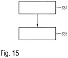
- Fig. 15 shows a flowchart of a possible exemplary embodiment of a further alternative method for providing orthogonality among the transmit antennas 3-i of a multiple input multiple output, MIMO, radar system according to a fifth aspect of the present invention.
- the illustrated method for providing orthogonality according to the fifth aspect of the present invention comprises two main steps.
- a first step S5A distinct time-coded data signals are transmitted from multiple, N t , transmit antennas 3-i of a multiple input multiple output, MIMO, radar antenna array.
- step S5B of the method for providing orthogonality according to the fifth aspect of the present invention signals received by multiple receive antennas 4-i of the multiple input multiple output, MIMO, radar antenna array are processed to separate a target response for all, N t , transmit antennas 3-i of the multiple input multiple output, MIMO, radar antenna array.
- the method for providing orthogonality among the transmit antennas can employ more than two transmit antennas.
- the coding is done only across time and can be used for both closely separated antennas and widely separated antennas.
- the method according to the fifth aspect of the present invention scales with multiple transmit antennas 3-i.
- the method for providing orthogonality according to the fifth aspect of the present invention can also be used for radar networks where individual radar apparatuses A in the radar network operate independently but where time and frequency is synchronized with other radar apparatuses within the radar network by a central control unit of the radar network.
- multiple transmit antennas 3-i of the multiple input multiple output MIMO radar antenna array can be collocated, i.e. located close to each other.
- the multiple transmit antennas 3-i of the multiple input multiple output, MIMO, radar antenna array can also be distributed and form part of a distributed radar network.
- the processing of the signals received by the multiple receive antennas 4-i of the multiple input multiple output, MIMO, radar antenna array 2 comprises a fast Fourier transformation processing FFT or a discrete Fourier transformation DFT processing.
- the time-coded data symbols transmitted from the multiple N t transmit antennas of the multiple input multiple output, MIMO, radar antenna array 2 used in the method according to the fifth aspect of the present invention can also comprise OFDM symbols.
- the method for providing orthogonality among transmit antennas can comprise two or more transmit antennas 3-i.
- a signal processing can be performed.
- Nx 1 data is transmitted on the N consecutive time indices
- the second transmit antenna 3-2 ( x 2 , ⁇ 1 x 2 , ⁇ 2 x 2 ,..., x 2 ) Nx 1
- data is transmitted on the N consecutive time indices and similarly on the N th transmit antenna ( x N, ⁇ N -1 x N , ⁇ 2( N -1) x N ,..., ⁇ ( N -1)( N -1) x N ), data are transmitted on N consecutive time indices.
- the target/channel response is separated from all the N t transmit antennas 3-i.
- the method for providing orthogonality among the transmit antennas 3-i according to the fifth aspect of the present invention requires few computational resources and scales for multiple transmit antennas 3-i easily.
- Fig. 16 illustrates the transmission of data from all N t transmit antennas 3-i across time and frequency for a target.
- Fig. 17 illustrates the received data from the receive antenna 4-i in response to the applied transmit time-coded data of all N t transmit antennas 3-i.
- the method for providing orthogonality according to the fifth aspect of the present invention has the advantage that it provides a time pulse diversity in the MIMO radar system.
- the method for providing orthogonality according to the fifth aspect of the present invention can also be applied to radar networks where all radar units are synchronized but all radar units require orthogonality or linear separability of the respective transmit signals for target imaging or target classification.
- Fig. 18 illustrates schematically a possible implementation of a radar network comprising different radar units each comprising one or several transmit antennas 3-i and receive antennas 4-i.
- the target object TO can be for instance a moving aeroplane as illustrated in Fig. 18 .
- the distance between the moving target object TO and the different radar units is illustrated as a radius r i .
- the radar units have a common reference point of a coordinate system origin at a distance of R i , respectively, as shown in Fig. 18 .
- the different radar units comprise a radar apparatus 1 such as illustrated in Figs. 1 , 10 .
- the MIMO radar system allows for detection of a moving target object TO more efficiently. Further, the resource allocation to detect the target object TO is optimized.
- the MIMO radar system according to the illustrated embodiments increases the signal to noise ratio SNR of the received signals making the detection of the target object TO more reliable.
- the method and radar apparatus 1 according to the different aspects of the present invention allow for detection of targets with a small radar cross-section RCS and/or a target object TO at a wide detection range.
- the method and radar apparatus 1 of the radar system can be used for radar signals in a wide frequency range, for instance from 4 to 100 GHz.
- the MIMO radar system according to the present invention can be used for different applications, for instance surveillance systems surveilling objects or targets in an open area or in automotive systems of cars. Further, the radar system can be used for fast-moving targets such as aeroplanes. The radar system can be used for tracking, surveillance and defence operations. The MIMO radar system can also be used for automotive radar apparatuses where power transmission is limited. The MIMO radar system can secure different kinds of information about the object or target including its position, its velocity and its aspect angle (azimuth, elevation) relative to the radar apparatus 1.
- the method according to the third aspect of the present invention and according to the fifth aspect of the present invention provide orthogonality among the transmit antennas 3-i of the radar system.
- the method according to the first aspect of the present invention provides for adaptive transmission of frequency subcarriers fc to improve efficiency of the radar system.
Landscapes
- Engineering & Computer Science (AREA)
- Radar, Positioning & Navigation (AREA)
- Remote Sensing (AREA)
- Computer Networks & Wireless Communication (AREA)
- Physics & Mathematics (AREA)
- General Physics & Mathematics (AREA)
- Radio Transmission System (AREA)
Applications Claiming Priority (3)
| Application Number | Priority Date | Filing Date | Title |
|---|---|---|---|
| IN201641043881 | 2016-12-22 | ||
| IN201641043893 | 2016-12-22 | ||
| IN201641043847 | 2016-12-22 |
Publications (1)
| Publication Number | Publication Date |
|---|---|
| EP3339895A1 true EP3339895A1 (fr) | 2018-06-27 |
Family
ID=59325230
Family Applications (3)
| Application Number | Title | Priority Date | Filing Date |
|---|---|---|---|
| EP17181032.8A Pending EP3339895A1 (fr) | 2016-12-22 | 2017-07-12 | Système radar à entrées et sorties multiples (mimo) |
| EP17181029.4A Pending EP3339892A1 (fr) | 2016-12-22 | 2017-07-12 | Système radar à entrées et sorties multiples (mimo) |
| EP17181035.1A Pending EP3339893A1 (fr) | 2016-12-22 | 2017-07-12 | Système radar à entrées et sorties multiples (mimo) |
Family Applications After (2)
| Application Number | Title | Priority Date | Filing Date |
|---|---|---|---|
| EP17181029.4A Pending EP3339892A1 (fr) | 2016-12-22 | 2017-07-12 | Système radar à entrées et sorties multiples (mimo) |
| EP17181035.1A Pending EP3339893A1 (fr) | 2016-12-22 | 2017-07-12 | Système radar à entrées et sorties multiples (mimo) |
Country Status (1)
| Country | Link |
|---|---|
| EP (3) | EP3339895A1 (fr) |
Cited By (6)
| Publication number | Priority date | Publication date | Assignee | Title |
|---|---|---|---|---|
| CN110579755A (zh) * | 2019-09-18 | 2019-12-17 | 四川天邑康和通信股份有限公司 | 一种高精度多普勒频率测速装置 |
| CN112346058A (zh) * | 2020-10-30 | 2021-02-09 | 西安电子科技大学 | 基于连续脉冲编码提升高速sar平台信噪比的成像方法 |
| CN113253249A (zh) * | 2021-04-19 | 2021-08-13 | 中国电子科技集团公司第二十九研究所 | 一种基于深度强化学习的mimo雷达功率分配设计方法 |
| CN113311402A (zh) * | 2021-04-16 | 2021-08-27 | 苏州迈斯维通信技术有限公司 | 考虑发射波形非理想正交的mimo雷达目标测向方法及系统 |
| US20220050197A1 (en) * | 2018-07-17 | 2022-02-17 | Aptiv Technologies Limited | Slow Time Frequency Division Multiplexing with Binary Phase Shifters |
| CN115015841A (zh) * | 2022-06-02 | 2022-09-06 | 中国人民解放军国防科技大学 | 基于多入多出阵列的探通扰一体化波形优化方法和系统 |
Families Citing this family (5)
| Publication number | Priority date | Publication date | Assignee | Title |
|---|---|---|---|---|
| CN110673120B (zh) * | 2019-09-18 | 2022-03-29 | 四川天邑康和通信股份有限公司 | 一种基于Zadoff-Chu序列的移动速率测定方法 |
| US10812154B1 (en) | 2019-10-22 | 2020-10-20 | Semiconductor Components Industries, Llc | MIMO radar with receive antenna multiplexing |
| US20230308248A1 (en) * | 2020-08-25 | 2023-09-28 | Interdigital Patent Holdings, Inc. | Methods and procedures for orthogonal radar communication |
| CN112834988B (zh) * | 2021-02-08 | 2023-02-17 | 上海保隆汽车科技股份有限公司 | 一种车载mimo雷达天线布局结构 |
| JP7345710B2 (ja) | 2021-09-07 | 2023-09-15 | 三菱電機株式会社 | 検出装置および検出方法 |
Citations (3)
| Publication number | Priority date | Publication date | Assignee | Title |
|---|---|---|---|---|
| US20110013716A1 (en) * | 2009-07-17 | 2011-01-20 | Mitre Corporation | Time-Frequency Space Constructions of Families of Signals |
| WO2017084664A2 (fr) | 2015-11-19 | 2017-05-26 | Schaeffler Technologies AG & Co. KG | Dispositif de réglage en hauteur du châssis d'un véhicule à moteur |
| WO2017084661A1 (fr) | 2015-11-19 | 2017-05-26 | Conti Temic Microelectronic Gmbh | Système radar à émission série et réception parallèle imbriquées |
Family Cites Families (4)
| Publication number | Priority date | Publication date | Assignee | Title |
|---|---|---|---|---|
| DE102011009874B3 (de) * | 2011-01-31 | 2012-04-12 | Karlsruher Institut für Technologie | Verfahren zur Sendesignaltrennung in einem Radarsystem und Radarsystem |
| DE102014206927A1 (de) * | 2014-04-10 | 2015-10-15 | Robert Bosch Gmbh | Verfahren zum Ermitteln einer Zeitmultiplexsequenz für ein MIMO Radar |
| CN104166132B (zh) * | 2014-08-14 | 2016-08-17 | 东南大学 | 一种非正交多载波相位编码雷达系统 |
| US10126421B2 (en) * | 2015-05-15 | 2018-11-13 | Maxlinear, Inc. | Dynamic OFDM symbol shaping for radar applications |
-
2017
- 2017-07-12 EP EP17181032.8A patent/EP3339895A1/fr active Pending
- 2017-07-12 EP EP17181029.4A patent/EP3339892A1/fr active Pending
- 2017-07-12 EP EP17181035.1A patent/EP3339893A1/fr active Pending
Patent Citations (3)
| Publication number | Priority date | Publication date | Assignee | Title |
|---|---|---|---|---|
| US20110013716A1 (en) * | 2009-07-17 | 2011-01-20 | Mitre Corporation | Time-Frequency Space Constructions of Families of Signals |
| WO2017084664A2 (fr) | 2015-11-19 | 2017-05-26 | Schaeffler Technologies AG & Co. KG | Dispositif de réglage en hauteur du châssis d'un véhicule à moteur |
| WO2017084661A1 (fr) | 2015-11-19 | 2017-05-26 | Conti Temic Microelectronic Gmbh | Système radar à émission série et réception parallèle imbriquées |
Non-Patent Citations (1)
| Title |
|---|
| CAO YUN-HE ET AL: "IRCI free colocated mimo radar based on sufficient cyclic prefix OFDM waveforms", IEEE TRANSACTIONS ON AEROSPACE AND ELECTRONIC SYSTEMS, IEEE SERVICE CENTER, PISCATAWAY, NJ, US, vol. 51, no. 3, 1 July 2015 (2015-07-01), pages 2107 - 2120, XP011670246, ISSN: 0018-9251, [retrieved on 20150921], DOI: 10.1109/TAES.2015.140526 * |
Cited By (10)
| Publication number | Priority date | Publication date | Assignee | Title |
|---|---|---|---|---|
| US20220050197A1 (en) * | 2018-07-17 | 2022-02-17 | Aptiv Technologies Limited | Slow Time Frequency Division Multiplexing with Binary Phase Shifters |
| US11726198B2 (en) * | 2018-07-17 | 2023-08-15 | Aptiv Technologies Limited | Slow time frequency division multiplexing with binary phase shifters |
| CN110579755A (zh) * | 2019-09-18 | 2019-12-17 | 四川天邑康和通信股份有限公司 | 一种高精度多普勒频率测速装置 |
| CN112346058A (zh) * | 2020-10-30 | 2021-02-09 | 西安电子科技大学 | 基于连续脉冲编码提升高速sar平台信噪比的成像方法 |
| CN112346058B (zh) * | 2020-10-30 | 2023-02-07 | 西安电子科技大学 | 基于连续脉冲编码提升高速sar平台信噪比的成像方法 |
| CN113311402A (zh) * | 2021-04-16 | 2021-08-27 | 苏州迈斯维通信技术有限公司 | 考虑发射波形非理想正交的mimo雷达目标测向方法及系统 |
| CN113311402B (zh) * | 2021-04-16 | 2022-03-01 | 苏州迈斯维通信技术有限公司 | 考虑发射波形非理想正交的mimo雷达目标测向方法及系统 |
| CN113253249A (zh) * | 2021-04-19 | 2021-08-13 | 中国电子科技集团公司第二十九研究所 | 一种基于深度强化学习的mimo雷达功率分配设计方法 |
| CN115015841A (zh) * | 2022-06-02 | 2022-09-06 | 中国人民解放军国防科技大学 | 基于多入多出阵列的探通扰一体化波形优化方法和系统 |
| CN115015841B (zh) * | 2022-06-02 | 2023-09-12 | 中国人民解放军国防科技大学 | 基于多入多出阵列的探通扰一体化波形优化方法和系统 |
Also Published As
| Publication number | Publication date |
|---|---|
| EP3339892A1 (fr) | 2018-06-27 |
| EP3339893A1 (fr) | 2018-06-27 |
Similar Documents
| Publication | Publication Date | Title |
|---|---|---|
| EP3339895A1 (fr) | Système radar à entrées et sorties multiples (mimo) | |
| Rahman et al. | Framework for a perceptive mobile network using joint communication and radar sensing | |
| Kumari et al. | Investigating the IEEE 802.11 ad standard for millimeter wave automotive radar | |
| EP3339894A1 (fr) | Système radar à entrées et sorties multiples (mimo) | |
| EP2463683B1 (fr) | Système de radar actif et procédé | |
| CN106291559A (zh) | 用于运行雷达设备的方法 | |
| EP2556385B2 (fr) | Système de mesure de compteur électronique | |
| EP3324201B1 (fr) | Forme d'onde de système de radar de véhicule | |
| Mishra et al. | Sub-Nyquist radar: Principles and prototypes | |
| AU2002340719A1 (en) | System and method for narrowband pre-detection signal processing for passive coherent location applications | |
| Kiviranta et al. | 5G radar: Scenarios, numerology and simulations | |
| Zhang et al. | Framework for an innovative perceptive mobile network using joint communication and sensing | |
| CN110333507A (zh) | 多发多收合成孔径雷达成像方法 | |
| Gaudio et al. | Hybrid digital-analog beamforming and MIMO radar with OTFS modulation | |
| Hosseini et al. | Wide band channel characterization for low altitude unmanned aerial system communication using software defined radios | |
| Zwanetski et al. | Waveform design for FMCW MIMO radar based on frequency division | |
| CN114073016A (zh) | 多流mimo/波束成形雷达 | |
| Keskin et al. | ICI-aware parameter estimation for MIMO-OFDM radar via APES spatial filtering | |
| JP2022085412A (ja) | レーダ装置 | |
| US11047972B2 (en) | Method, apparatus and device for determining a velocity of an object in a time switched MIMO radar system | |
| Bekar et al. | Realization of a joint MIMO radar and communication system using a PSK-LFM waveform | |
| Sun et al. | Embedding the radio imaging in 5G networks: Signal processing and an airport use case | |
| Wojaczek et al. | Range compression strategies for passive radar on airborne platforms | |
| Cao | Cellular Base Station Imaging for UAV Detection | |
| CN113740823A (zh) | 适用于机载多通道合成孔径雷达的运动目标信号处理方法 |
Legal Events
| Date | Code | Title | Description |
|---|---|---|---|
| PUAI | Public reference made under article 153(3) epc to a published international application that has entered the european phase |
Free format text: ORIGINAL CODE: 0009012 |
|
| STAA | Information on the status of an ep patent application or granted ep patent |
Free format text: STATUS: THE APPLICATION HAS BEEN PUBLISHED |
|
| AK | Designated contracting states |
Kind code of ref document: A1 Designated state(s): AL AT BE BG CH CY CZ DE DK EE ES FI FR GB GR HR HU IE IS IT LI LT LU LV MC MK MT NL NO PL PT RO RS SE SI SK SM TR |
|
| AX | Request for extension of the european patent |
Extension state: BA ME |
|
| STAA | Information on the status of an ep patent application or granted ep patent |
Free format text: STATUS: REQUEST FOR EXAMINATION WAS MADE |
|
| 17P | Request for examination filed |
Effective date: 20181220 |
|
| RBV | Designated contracting states (corrected) |
Designated state(s): AL AT BE BG CH CY CZ DE DK EE ES FI FR GB GR HR HU IE IS IT LI LT LU LV MC MK MT NL NO PL PT RO RS SE SI SK SM TR |
|
| STAA | Information on the status of an ep patent application or granted ep patent |
Free format text: STATUS: REQUEST FOR EXAMINATION WAS MADE |
|
| STAA | Information on the status of an ep patent application or granted ep patent |
Free format text: STATUS: EXAMINATION IS IN PROGRESS |
|
| STAA | Information on the status of an ep patent application or granted ep patent |
Free format text: STATUS: EXAMINATION IS IN PROGRESS |
|
| 17Q | First examination report despatched |
Effective date: 20210303 |
|
| TPAC | Observations filed by third parties |
Free format text: ORIGINAL CODE: EPIDOSNTIPA |