EP3339780A1 - Aufgereihte kühlvorrichtungen - Google Patents
Aufgereihte kühlvorrichtungen Download PDFInfo
- Publication number
- EP3339780A1 EP3339780A1 EP16877165.7A EP16877165A EP3339780A1 EP 3339780 A1 EP3339780 A1 EP 3339780A1 EP 16877165 A EP16877165 A EP 16877165A EP 3339780 A1 EP3339780 A1 EP 3339780A1
- Authority
- EP
- European Patent Office
- Prior art keywords
- door body
- claw
- elastic piece
- hanger
- locking
- Prior art date
- Legal status (The legal status is an assumption and is not a legal conclusion. Google has not performed a legal analysis and makes no representation as to the accuracy of the status listed.)
- Granted
Links
Images

Classifications
-
- F—MECHANICAL ENGINEERING; LIGHTING; HEATING; WEAPONS; BLASTING
- F25—REFRIGERATION OR COOLING; COMBINED HEATING AND REFRIGERATION SYSTEMS; HEAT PUMP SYSTEMS; MANUFACTURE OR STORAGE OF ICE; LIQUEFACTION SOLIDIFICATION OF GASES
- F25D—REFRIGERATORS; COLD ROOMS; ICE-BOXES; COOLING OR FREEZING APPARATUS NOT OTHERWISE PROVIDED FOR
- F25D23/00—General constructional features
- F25D23/02—Doors; Covers
- F25D23/028—Details
-
- E—FIXED CONSTRUCTIONS
- E05—LOCKS; KEYS; WINDOW OR DOOR FITTINGS; SAFES
- E05C—BOLTS OR FASTENING DEVICES FOR WINGS, SPECIALLY FOR DOORS OR WINDOWS
- E05C7/00—Fastening devices specially adapted for two wings
- E05C7/04—Fastening devices specially adapted for two wings for wings which abut when closed
-
- E—FIXED CONSTRUCTIONS
- E05—LOCKS; KEYS; WINDOW OR DOOR FITTINGS; SAFES
- E05B—LOCKS; ACCESSORIES THEREFOR; HANDCUFFS
- E05B65/00—Locks or fastenings for special use
- E05B65/0042—For refrigerators or cold rooms
-
- E—FIXED CONSTRUCTIONS
- E05—LOCKS; KEYS; WINDOW OR DOOR FITTINGS; SAFES
- E05C—BOLTS OR FASTENING DEVICES FOR WINGS, SPECIALLY FOR DOORS OR WINDOWS
- E05C1/00—Fastening devices with bolts moving rectilinearly
- E05C1/004—Fastening devices with bolts moving rectilinearly parallel to the surface on which the fastener is mounted
- E05C1/006—Fastening devices with bolts moving rectilinearly parallel to the surface on which the fastener is mounted parallel to the wing edge
-
- E—FIXED CONSTRUCTIONS
- E05—LOCKS; KEYS; WINDOW OR DOOR FITTINGS; SAFES
- E05C—BOLTS OR FASTENING DEVICES FOR WINGS, SPECIALLY FOR DOORS OR WINDOWS
- E05C1/00—Fastening devices with bolts moving rectilinearly
- E05C1/08—Fastening devices with bolts moving rectilinearly with latching action
- E05C1/085—With means for assisting depression of the latch bolt during latching
-
- E—FIXED CONSTRUCTIONS
- E05—LOCKS; KEYS; WINDOW OR DOOR FITTINGS; SAFES
- E05C—BOLTS OR FASTENING DEVICES FOR WINGS, SPECIALLY FOR DOORS OR WINDOWS
- E05C19/00—Other devices specially designed for securing wings, e.g. with suction cups
- E05C19/02—Automatic catches, i.e. released by pull or pressure on the wing
-
- F—MECHANICAL ENGINEERING; LIGHTING; HEATING; WEAPONS; BLASTING
- F25—REFRIGERATION OR COOLING; COMBINED HEATING AND REFRIGERATION SYSTEMS; HEAT PUMP SYSTEMS; MANUFACTURE OR STORAGE OF ICE; LIQUEFACTION SOLIDIFICATION OF GASES
- F25D—REFRIGERATORS; COLD ROOMS; ICE-BOXES; COOLING OR FREEZING APPARATUS NOT OTHERWISE PROVIDED FOR
- F25D23/00—General constructional features
- F25D23/02—Doors; Covers
-
- F—MECHANICAL ENGINEERING; LIGHTING; HEATING; WEAPONS; BLASTING
- F25—REFRIGERATION OR COOLING; COMBINED HEATING AND REFRIGERATION SYSTEMS; HEAT PUMP SYSTEMS; MANUFACTURE OR STORAGE OF ICE; LIQUEFACTION SOLIDIFICATION OF GASES
- F25D—REFRIGERATORS; COLD ROOMS; ICE-BOXES; COOLING OR FREEZING APPARATUS NOT OTHERWISE PROVIDED FOR
- F25D2323/00—General constructional features not provided for in other groups of this subclass
- F25D2323/02—Details of doors or covers not otherwise covered
- F25D2323/021—French doors
Definitions
- the present disclosure relates to a technical field of electric appliance manufacture, and specifically to a side-by-side refrigerator.
- the present disclosure seeks to solve one of the technical problems existing in the related art to at least some extent.
- the present disclosure provides a side-by-side refrigerator which has advantages of a simple structure, low cost, high production efficiency and etc.
- the side-by-side refrigerator includes: a refrigerator body having a refrigerating compartment therein; a left door body and a right door body pivotably arranged on the refrigerator body respectively so as to jointly open and close the refrigerating compartment, the left door body being provided with a left door seal and the right door body being provided with a right door seal; and a door body locking assembly, in which when the left door body and the right door body close the refrigerating compartment, the left door body and the right door body are locked by the door body locking assembly and the left door seal and the right door seal jointly seal a gap between the left door body and the right door body.
- the side-by-side refrigerator according to embodiments of the present disclosure has the advantages of a simple structure, low cost, high production efficiency and etc.
- the side-by-side refrigerator according to embodiments of the present disclosure further has the following additional technical features:
- the left door body is provided with a left hanger and the right door body is provided with a right hanger, and the left hanger and the right hanger are locked by the door body locking assembly when the left door body and the right door body close the refrigerating compartment.
- the door body locking assembly includes: a casing provided to the refrigerator body; a left claw and a right claw, the left claw and the right claw being rotatably disposed to the casing separately; a left elastic piece and a right elastic piece, the left elastic piece being compressed between the casing and the left claw and the right elastic piece being compressed between the casing and the right claw, in which when the left door body and the right door body close the refrigerating compartment, the left hanger is hooked by the left claw under an action of the left elastic piece and the right hanger is hooked by the right claw under an action of the right elastic piece.
- the left hanger is provided with a left locking lug having a circular cross section
- the left claw is provided with a left guiding slope and a left locking arc surface located behind the left guiding slope
- the right hanger is provided with a right locking lug having a circular cross section
- the right claw is provided with a right guiding slope and a right locking arc surface located behind the right guiding slope
- the left claw and the right claw are arranged opposite to each other in left and right directions, and a rotation axis of the left claw and a rotation axis of the right claw are parallel and oriented in up and down directions.
- the casing is located at a center of the refrigerator body in left and right directions, the left hanger is disposed to a rear surface of the left door body and adjacent to a right side face of the left door body, and the right hanger is disposed to a rear surface of the right door body and adjacent to a left side surface of the right door body.
- the casing includes a body having an accommodating cavity, the accommodating cavity having an open rear surface, a front surface of the body being provided with a locking opening communicated with the accommodating cavity, the left claw, the right claw, the left elastic piece and the right elastic piece being all arranged in the accommodating cavity, and the left claw extending into the locking opening under an action of the left elastic piece and the right claw extending into the locking opening under an action of the right elastic piece; and a cover detachably mounted to the body and covering the rear surface of the accommodating cavity.
- the left claw is provided with a left rotation shaft
- the right claw is provided with a right rotation shaft
- the cover and the body jointly define a left rotation shaft groove and a right rotation shaft groove
- the left rotation shaft is rotatably fitted in the left rotation shaft groove
- the right rotation shaft is rotatably fitted in the right rotation shaft groove.
- the left elastic piece and the right elastic piece are both springs, a left side surface of the left claw is provided with a left positioning column and a right side surface of the right claw is provided with a right positioning column, the left elastic piece has a first left end abutted against a left side wall of the accommodating cavity and a first right end fitted over the left positioning column, the right elastic piece has a second left end fitted over the right positioning column and a second right end abutted against a right side wall of the accommodating cavity.
- two door body locking assemblies are provided and disposed to an upper face and a lower face of the refrigerating compartment respectively.
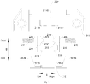
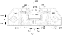
- FIG. 1 side-by-side refrigerator 1, left door body 110, left door seal 111, left hanger 112, left locking lug 1120, right door body 120, right door seal 121, right hanger 122, right locking lug 1220, door body locking assembly 200, casing 210, body 211, locking opening 2110, left rotation shaft groove 2111, right rotation shaft groove 2112, cover 212, left limiting rib 2121, right limiting rib 2122, left limiting plate 2123, right limiting plate 2124, left claw 220, left guiding slope 221, left locking arc surface 222, left rotation shaft 223, left positioning column 224, right claw 230, right guiding slope 231, right locking arc surface 232, right rotation shaft 233, right positioning column 234, left elastic piece 241, right elastic piece 242.
- a side-by-side refrigerator 1 according to embodiments of the present disclosure is described in the following with reference to the accompany drawings.
- the side-by-side refrigerator 1 includes a refrigerator body (not illustrated in the figures), a left door body 110, a right door body 120 and a door body locking assembly 200 (left and right directions are shown by an arrow C in Fig. 1 to Fig. 4 ).
- the refrigerator body is provided with a refrigerating compartment therein.
- the left door body 110 and the right door body 120 are pivotably arranged on the refrigerator body respectively so as to jointly open and close the refrigerating compartment, and the left door body 110 and the right door body 120 are arranged to be opened oppositely.
- the left door body 110 is provided with a left door seal 111 and the right door body 120 is provided with a right door seal 121.
- the left door body 110 and the right door body 120 close the refrigerating compartment, the left door body 110 and the right door body 120 are locked by the door body locking assembly 200 and the left door seal 111 and the right door seal 121 jointly seal a gap between the left door body 110 and the right door body 120.
- the left door body 110 and the right door body 120 can be locked by mean of the door body locking assembly 200, so as to lock the left door body 110 and the right door body 120 when the left door body 110 and the right door body 120 jointly close the refrigerating compartment, thus preventing the left door body 110 and the right door body 120 from being opened in cases except that the users open the left door body 110 and the right door body 120 on their own initiative, and guaranteeing reliability of the left door body 110 and the right door body 120 for closing the refrigerating compartment.
- the left door seal 111 to the left door body 110 and arranging the right door seal 121 to the right door body 120, it is possible to jointly seal the gap between the left door body 110 and the right door body 120 by means of the left door seal 111 and the right door seal 121 when the left door body 110 and the right door body 120 close the refrigerating compartment. Furthermore, as the left door body 110 and the right door body 120 are locked by the door body locking assembly 200 when the left door body 110 and the right door body 120 close the refrigerating compartment, it is possible to further guarantee sealing effect on the gap between the left door body 110 and the right door body 120 by means of the left door seal 111 and the right door seal 121, thus guaranteeing the leakproofhess of the refrigerating compartment.
- the gap between the left door body 110 and the right door body 120 of the side-by-side refrigerator 1 is sealed by the left door seal 111 and the right door seal 121 and the left door body 110 and the right door body 120 are locked by means of the door body locking assembly 200, compared with the manner in related art that the gap between door bodies is sealed by means of a turnover beam, it is possible to not only omit the part cost of the turnover beam, further simplify the structure of the side-by-side refrigerator 1, reduce the number of the parts of the side-by-side refrigerator 1 and hence the manufacture cost of the side-by-side refrigerator 1, but also omit assembly procedure for mounting the turnover beam, simplify the assembly process of the side-by-side refrigerator 1, improve the production efficiency of the side-by-side refrigerator 1, reduce the operation intensity of installation personnel so as to reduce labor cost, thus further reduce the production cost of the side-by-side refrigerator 1.
- the side-by-side refrigerator 1 has advantages of a simple structure, low cost, high production efficiency and etc.
- the side-by-side refrigerator 1 includes the refrigerator body, the left door body 110, the right door body 120 and the door body locking assembly 200.
- the left door seal 111 is located at a right side wall of the left door body 110 and disposed adjacent to a rear surface of the left door body 110
- the right door seal 121 is located at a left side wall of the right door body 120 and disposed adjacent to a rear surface of the right door body 120.
- the left door body 110 is provided with a left hanger 112 and the right door body 120 is provided with a right hanger 122, and the left hanger 112 and the right hanger 122 are locked by the door body locking assembly 200 when the left door body 110 and the right door body 120 close the refrigerating compartment.
- the left hanger 112 and the right hanger 122 can be conveniently used to position the left door body 110 and the right door body 120, such that the door body locking assembly 200 can conveniently lock the left door body 110 and the right door body 120.
- the door body locking assembly 200 includes a casing 210, a left claw 220, a right claw 230, a left elastic piece 241 and a right elastic piece 242.
- the casing 210 is provided to the refrigerator body.
- the left claw 220 and the right claw 230 are rotatably disposed to the casing 210 separately.
- the left elastic piece 241 is compressed between the casing 210 and the left claw 220 and the right elastic piece 242 is compressed between the casing 210 and the right claw 230.
- the left hanger 112 is hooked by the left claw 220 under the action of the left elastic piece 241 and the right hanger 122 is hooked by the right claw 230 under the action of the right elastic piece 242.
- the left claw 220 and the right claw 230 can be squeezed by the left hanger 112 and the right hanger 122, enabling the left claw 220 and the right claw 230 to overcome an elastic force of the elastic piece to rotate, thereby facilitating the opening and locking of the door body.
- the left door body 110 by means of the left hanger 112 and the left claw 220 and lock the right door body 120 by means of the right hanger 122 and the right claw 230, which not only releases the user from considering the sequence of door opening, thus improving the convenience of the side-by-side refrigerator 1, but also facilitates the assembly of the door body locking assembly 200 by providing the casing 210.
- the left claw 220, the right claw 230, the left elastic piece 241 and the right elastic piece 242 can be firstly mounted to the casing 210 to form the door body locking assembly 200, and the door body locking assembly 200 can be then mounted to the refrigerator body.
- the left hanger 112 is provided with a left locking lug 1120 having a circular cross section
- the left claw 220 is provided with a left guiding slope 221 and a left locking arc surface 222 located behind the left guiding slope 221
- the right hanger 122 is provided with a right locking lug 1220 having a circular cross section
- the right claw 230 is provided with a right guiding slope 231 and a right locking arc surface 232 located behind the right guiding slope 231.
- the left claw 220 is hooked to the left locking arc surface 222 under a guidance of the left guiding slope 221 and the right claw 230 is hooked to the right locking arc surface 232 under a guidance of the right guiding slope 231.
- the left locking lug 1120 can be located at a left side wall of the left hanger 112 and disposed adjacent to a rear end of the left hanger 112
- the right locking lug 1220 can be located at a right side wall of the right hanger 122 and disposed adjacent to a rear end of the right hanger 122 (front and rear directions are shown by an arrow B in Fig. 1 to Fig. 4 ).
- the processes of opening and closing the door body can be more smooth, so as to facilitate the opening and closing of the door body, and the opening of the door body by itself in conditions where the user doesn't apply a force to the door body can be prevented, so as to guarantee the reliability of the side-by-side refrigerator 1.
- the left claw 220 and the right claw 230 are arranged opposite to each other in the left and right directions, and a rotation axis of the left claw 220 and a rotation axis of the right claw 230 are parallel and oriented along up and down directions.
- the left claw 220 and the right claw 230 can be enabled to rotate in a horizontal direction, so as to facilitate the opening and closing of the door body in the horizontal direction.
- the casing 210 is located at a center of the refrigerator body in the left and right directions, the left hanger 112 is disposed to the rear surface of the left door body 110 and adjacent to a right side surface of the left door body 110, the right hanger 122 is disposed to the rear surface of the right door body 120 and adjacent to a left side surface of the right door body 120.
- the door body locking assembly 200 can be applied to refrigerators having the left door body 110 and the right door body 120 of same size, and locking effect on the left door body 110 and the right door body 120 by means of the door body locking assembly 200 as well as sealing effect on the gap between the left door body 110 and the right door body 120 can be improved.
- the casing 210 can also be not disposed at the center of the refrigerator body in the horizontal direction, so as to enable the door body locking assembly 200 to be applied to refrigerators having door bodies of different sizes.
- the casing 210 can be mounted to the refrigerator body by means of threaded fasteners.
- the casing 210 includes a body 211 and a cover 212.
- the body 211 has an accommodating cavity, the accommodating cavity has an open rear surface, a front surface of the body 211 is provided with a locking opening 2110 communicated with the accommodating cavity.
- the left claw 220, the right claw 230, the left elastic piece 241 and the right elastic piece 242 are all arranged in the accommodating cavity.
- the left claw 220 extends into the locking opening 2110 under the action of the left elastic piece 241 and the right claw 230 extends into the locking opening 2110 under the action of the right elastic piece 242.
- the cover 212 is detachably mounted to the body 211 and covers the rear surface of the accommodating cavity. Thus, it is convenient for the assembly and disassembly of the door body locking assembly 200, so as to facilitate the detachment and repair of the door body locking assembly 200.
- the left claw 220 is provided with a left rotation shaft 223
- the right claw 230 is provided with a right rotation shaft 233
- the cover 212 and the body 211 jointly define a left rotation shaft groove 2111 and a right rotation shaft groove 2112
- the left rotation shaft 223 is rotataly fitted in the left rotation shaft groove
- the right rotation shaft 233 is rotatably fitted in the right rotation shaft groove.
- the cover 212 is provided with a left limiting rib 2121 and a right limiting rib 2122
- the body 211 can be provided with a left notch and a right notch
- the left notch and the left limiting rib 2121 jointly define the left rotation shaft groove 2111
- the right notch and the right limiting rib 2122 jointly define the right rotation shaft groove 2112.
- the rotation shaft can be firstly fitted in the notch, and then be positioned by using the limiting rib, to prevent the rotation shaft from breaking away from the notch.
- the left elastic piece 241 and the right elastic piece 242 are both springs, a left side surface of the left claw 220 is provided with a left positioning column 224 and a right side surface of the right claw 230 is provided with a right positioning column 234.
- the left elastic piece 241 has a first left end abutted against a left side wall of the accommodating cavity and a first right end fitted over the left positioning column 224
- the right elastic piece 242 has a second left end fitted over the right positioning column 234 and a second right end abutted against a right side wall of the accommodating cavity.
- the ends of the springs adjacent to the claws can be positioned by means of the left positioning column 224 and the right positioning column 234, so as to improve the stability of the springs.
- the casing 210 can be provided with a left limiting plate 2123 and a right limiting plate 2124.
- the left end of the left elastic piece 241 can be abutted between a front end of the left limiting plate 2123 and an inner wall of the body 211
- the right end of the right elastic piece 242 can be abutted between a front end of the right limiting plate 2124 and an inner wall of the body 211, thus the left end of the left elastic piece 241 and the right end of the right elastic piece 242 can be further positioned so as to improve the stability of the springs further.
- two door body locking assemblies are provided and disposed to an upper surface and a lower surface of the refrigerating compartment respectively.
- first and second are used herein for purposes of description and are not intended to indicate or imply relative importance or significance or to imply the number of indicated technical features.
- the feature defined with “first” and “second” may comprise one or more of this feature.
- a plurality of' means two or more than two, unless specified otherwise.
- the terms “mounted,” “connected,” “coupled,” “fixed” and the like are used broadly, and may be, for example, fixed connections, detachable connections, or integral connections; may also be mechanical connection, electrical connections, or be communicable to each other; may also be direct connections or indirect connections via intervening structures; may also be inner communications or interaction relationship of two elements, which can be understood by those skilled in the art according to specific situations.
- a structure in which a first feature is "on" or “below” a second feature may include an embodiment in which the first feature is in direct contact with the second feature, and may also include an embodiment in which the first feature and the second feature are not in direct contact with each other, but are contacted via an additional feature formed therebetween.
- a first feature "on,” “above,” or “on top of' a second feature may include an embodiment in which the first feature is right or obliquely “on,” “above,” or “on top of' the second feature, or just means that the first feature is at a height higher than that of the second feature; while a first feature "below,” “under,” or “on bottom of' a second feature may include an embodiment in which the first feature is right or obliquely “below,” “under,” or “on bottom of' the second feature, or just means that the first feature is at a height lower than that of the second feature.
Landscapes
- Engineering & Computer Science (AREA)
- Mechanical Engineering (AREA)
- Physics & Mathematics (AREA)
- Thermal Sciences (AREA)
- Chemical & Material Sciences (AREA)
- Combustion & Propulsion (AREA)
- General Engineering & Computer Science (AREA)
- Refrigerator Housings (AREA)
Applications Claiming Priority (3)
| Application Number | Priority Date | Filing Date | Title |
|---|---|---|---|
| CN201510981560.4A CN105423686B (zh) | 2015-12-22 | 2015-12-22 | 对开门冰箱 |
| CN201521088333.0U CN205332647U (zh) | 2015-12-22 | 2015-12-22 | 对开门冰箱 |
| PCT/CN2016/079978 WO2017107351A1 (zh) | 2015-12-22 | 2016-04-22 | 对开门冰箱 |
Publications (3)
| Publication Number | Publication Date |
|---|---|
| EP3339780A1 true EP3339780A1 (de) | 2018-06-27 |
| EP3339780A4 EP3339780A4 (de) | 2018-12-19 |
| EP3339780B1 EP3339780B1 (de) | 2020-10-28 |
Family
ID=59088925
Family Applications (1)
| Application Number | Title | Priority Date | Filing Date |
|---|---|---|---|
| EP16877165.7A Active EP3339780B1 (de) | 2015-12-22 | 2016-04-22 | Side-by-side-kühlschrank |
Country Status (3)
| Country | Link |
|---|---|
| US (1) | US10309714B2 (de) |
| EP (1) | EP3339780B1 (de) |
| WO (1) | WO2017107351A1 (de) |
Families Citing this family (5)
| Publication number | Priority date | Publication date | Assignee | Title |
|---|---|---|---|---|
| KR102721610B1 (ko) * | 2016-12-08 | 2024-10-25 | 삼성전자주식회사 | 냉장고 |
| CN209179655U (zh) * | 2018-08-01 | 2019-07-30 | 宁波市攸曼儿童防护用品有限公司 | 一种锁紧装置及其冰箱 |
| CN211795265U (zh) * | 2019-01-28 | 2020-10-30 | 欧蒙医学诊断(中国)有限公司 | 一种tip头盒定位机构及仪器 |
| CN114136040B (zh) * | 2020-09-04 | 2023-09-29 | 青岛海尔电冰箱有限公司 | 冰箱 |
| CN115164474A (zh) * | 2021-04-02 | 2022-10-11 | 合肥海尔电冰箱有限公司 | 一种冰箱 |
Family Cites Families (18)
| Publication number | Priority date | Publication date | Assignee | Title |
|---|---|---|---|---|
| US1918911A (en) | 1931-12-24 | 1933-07-18 | Rex Mfg Co Inc | Refrigerator cabinet |
| US2692809A (en) | 1952-02-21 | 1954-10-26 | Gen Motors Corp | Refrigerating apparatus |
| US2767040A (en) * | 1954-02-15 | 1956-10-16 | Gen Motors Corp | Refrigerating apparatus |
| US3583737A (en) * | 1969-11-07 | 1971-06-08 | Zenzi Tutikawa | Locking apparatus for set of swinging doors |
| KR970004281Y1 (ko) * | 1992-12-17 | 1997-05-08 | 윤종용 | 냉장고용 도어의 홀딩장치 |
| JP3682015B2 (ja) * | 2000-11-06 | 2005-08-10 | 松下冷機株式会社 | 扉装置および扉装置を備えた冷蔵庫 |
| ATE306153T1 (de) | 2001-01-31 | 2005-10-15 | Verfahren und anordnung zur übertragung in einem optischen netzwerk | |
| DE10117782A1 (de) * | 2001-04-09 | 2002-10-17 | Bsh Bosch Siemens Hausgeraete | Kältegerät mit Türsicherung |
| KR100659661B1 (ko) * | 2004-06-08 | 2006-12-21 | 엘지전자 주식회사 | 냉장고용 도어열림방지장치 |
| KR100707435B1 (ko) * | 2005-02-28 | 2007-04-13 | 엘지전자 주식회사 | 냉장고의 도어 개폐 장치 |
| KR100707450B1 (ko) * | 2005-04-16 | 2007-04-13 | 엘지전자 주식회사 | 냉장고의 도어 개폐 장치 |
| CN201810072U (zh) * | 2009-12-15 | 2011-04-27 | 海信容声(广东)冰箱有限公司 | 一种左右开门型冰箱的门锁 |
| CN201858833U (zh) | 2010-07-09 | 2011-06-08 | 安徽尊贵电器集团有限公司 | 一种对挤门封 |
| CN202074770U (zh) * | 2011-05-19 | 2011-12-14 | 六安索伊电器制造有限公司 | 冰箱侧面门封 |
| WO2013082765A1 (zh) * | 2011-12-06 | 2013-06-13 | 合肥美的荣事达电冰箱有限公司 | 冰箱及用于冰箱的门体锁紧组件 |
| CN102518348B (zh) * | 2011-12-06 | 2014-10-22 | 合肥美的电冰箱有限公司 | 冰箱及用于冰箱的门体锁紧组件 |
| CN105423686B (zh) * | 2015-12-22 | 2019-01-22 | 合肥华凌股份有限公司 | 对开门冰箱 |
| CN205332647U (zh) | 2015-12-22 | 2016-06-22 | 合肥华凌股份有限公司 | 对开门冰箱 |
-
2016
- 2016-04-22 US US15/760,633 patent/US10309714B2/en active Active
- 2016-04-22 EP EP16877165.7A patent/EP3339780B1/de active Active
- 2016-04-22 WO PCT/CN2016/079978 patent/WO2017107351A1/zh not_active Ceased
Also Published As
| Publication number | Publication date |
|---|---|
| US20180299186A1 (en) | 2018-10-18 |
| WO2017107351A1 (zh) | 2017-06-29 |
| US10309714B2 (en) | 2019-06-04 |
| EP3339780A4 (de) | 2018-12-19 |
| EP3339780B1 (de) | 2020-10-28 |
Similar Documents
| Publication | Publication Date | Title |
|---|---|---|
| EP3339780A1 (de) | Aufgereihte kühlvorrichtungen | |
| US10934756B2 (en) | Refrigerator | |
| JP5535035B2 (ja) | ヒンジ装置及びそれを用いた超低温フリーザ | |
| US20160084567A1 (en) | Anchor assemblies and mounting kits for connecting door handles to doors of refrigerator appliances | |
| US12031769B2 (en) | Attachment assembly for an insulated door | |
| US11268708B2 (en) | Outdoor unit for central air conditioner and central air conditioner having same | |
| CN105423686B (zh) | 对开门冰箱 | |
| EP3428558B1 (de) | Ultratieftemperaturgefriergerät | |
| US8926033B2 (en) | Door closure structure for rotary door and side-by-side refrigerator comprising the same | |
| US11408666B2 (en) | Refrigeration appliance cabinet thermal insulation container and refrigeration appliance | |
| KR101594334B1 (ko) | 차량의 엠블럼 일체형 트렁크 스위치 어셈블리 | |
| AU2015307547A1 (en) | Refrigerator door and refrigerator | |
| EP2789942B1 (de) | Kühlschrank und türverriegelungselement zur verwendung in diesem kühlschrank | |
| US2137165A (en) | Refrigerator cabinet | |
| US10194494B2 (en) | Microwave cooking device | |
| CN103256783B (zh) | 冰箱 | |
| US20180187959A1 (en) | Refrigeration appliance | |
| CN205332647U (zh) | 对开门冰箱 | |
| CN106193827A (zh) | 制冷设备用柜体及制冷设备 | |
| CN209658666U (zh) | 一种采用活动走线加强筋的电器箱柜门 | |
| CN205531828U (zh) | 汽车门把手罩盖安装结构 | |
| CN216162157U (zh) | 电气柜 | |
| CN102494482A (zh) | 用于冰箱的吧台内罩组件及具有它的冰箱 | |
| CN103615852B (zh) | 冰箱 | |
| US12480707B2 (en) | Vertical beam assembly for refrigerator door and refrigerator |
Legal Events
| Date | Code | Title | Description |
|---|---|---|---|
| STAA | Information on the status of an ep patent application or granted ep patent |
Free format text: STATUS: THE INTERNATIONAL PUBLICATION HAS BEEN MADE |
|
| PUAI | Public reference made under article 153(3) epc to a published international application that has entered the european phase |
Free format text: ORIGINAL CODE: 0009012 |
|
| STAA | Information on the status of an ep patent application or granted ep patent |
Free format text: STATUS: REQUEST FOR EXAMINATION WAS MADE |
|
| 17P | Request for examination filed |
Effective date: 20180314 |
|
| AK | Designated contracting states |
Kind code of ref document: A1 Designated state(s): AL AT BE BG CH CY CZ DE DK EE ES FI FR GB GR HR HU IE IS IT LI LT LU LV MC MK MT NL NO PL PT RO RS SE SI SK SM TR |
|
| AX | Request for extension of the european patent |
Extension state: BA ME |
|
| A4 | Supplementary search report drawn up and despatched |
Effective date: 20181115 |
|
| RIC1 | Information provided on ipc code assigned before grant |
Ipc: E05C 19/02 20060101ALI20181109BHEP Ipc: F25D 23/02 20060101AFI20181109BHEP Ipc: E05C 7/04 20060101ALI20181109BHEP |
|
| DAV | Request for validation of the european patent (deleted) | ||
| DAX | Request for extension of the european patent (deleted) | ||
| GRAP | Despatch of communication of intention to grant a patent |
Free format text: ORIGINAL CODE: EPIDOSNIGR1 |
|
| STAA | Information on the status of an ep patent application or granted ep patent |
Free format text: STATUS: GRANT OF PATENT IS INTENDED |
|
| INTG | Intention to grant announced |
Effective date: 20200814 |
|
| GRAS | Grant fee paid |
Free format text: ORIGINAL CODE: EPIDOSNIGR3 |
|
| GRAA | (expected) grant |
Free format text: ORIGINAL CODE: 0009210 |
|
| STAA | Information on the status of an ep patent application or granted ep patent |
Free format text: STATUS: THE PATENT HAS BEEN GRANTED |
|
| AK | Designated contracting states |
Kind code of ref document: B1 Designated state(s): AL AT BE BG CH CY CZ DE DK EE ES FI FR GB GR HR HU IE IS IT LI LT LU LV MC MK MT NL NO PL PT RO RS SE SI SK SM TR |
|
| REG | Reference to a national code |
Ref country code: GB Ref legal event code: FG4D |
|
| REG | Reference to a national code |
Ref country code: CH Ref legal event code: EP |
|
| REG | Reference to a national code |
Ref country code: AT Ref legal event code: REF Ref document number: 1328627 Country of ref document: AT Kind code of ref document: T Effective date: 20201115 |
|
| REG | Reference to a national code |
Ref country code: DE Ref legal event code: R096 Ref document number: 602016046911 Country of ref document: DE |
|
| REG | Reference to a national code |
Ref country code: IE Ref legal event code: FG4D |
|
| REG | Reference to a national code |
Ref country code: AT Ref legal event code: MK05 Ref document number: 1328627 Country of ref document: AT Kind code of ref document: T Effective date: 20201028 |
|
| REG | Reference to a national code |
Ref country code: NL Ref legal event code: MP Effective date: 20201028 |
|
| PG25 | Lapsed in a contracting state [announced via postgrant information from national office to epo] |
Ref country code: RS Free format text: LAPSE BECAUSE OF FAILURE TO SUBMIT A TRANSLATION OF THE DESCRIPTION OR TO PAY THE FEE WITHIN THE PRESCRIBED TIME-LIMIT Effective date: 20201028 Ref country code: PT Free format text: LAPSE BECAUSE OF FAILURE TO SUBMIT A TRANSLATION OF THE DESCRIPTION OR TO PAY THE FEE WITHIN THE PRESCRIBED TIME-LIMIT Effective date: 20210301 Ref country code: NO Free format text: LAPSE BECAUSE OF FAILURE TO SUBMIT A TRANSLATION OF THE DESCRIPTION OR TO PAY THE FEE WITHIN THE PRESCRIBED TIME-LIMIT Effective date: 20210128 Ref country code: FI Free format text: LAPSE BECAUSE OF FAILURE TO SUBMIT A TRANSLATION OF THE DESCRIPTION OR TO PAY THE FEE WITHIN THE PRESCRIBED TIME-LIMIT Effective date: 20201028 |
|
| REG | Reference to a national code |
Ref country code: LT Ref legal event code: MG4D |
|
| PG25 | Lapsed in a contracting state [announced via postgrant information from national office to epo] |
Ref country code: IS Free format text: LAPSE BECAUSE OF FAILURE TO SUBMIT A TRANSLATION OF THE DESCRIPTION OR TO PAY THE FEE WITHIN THE PRESCRIBED TIME-LIMIT Effective date: 20210228 Ref country code: PL Free format text: LAPSE BECAUSE OF FAILURE TO SUBMIT A TRANSLATION OF THE DESCRIPTION OR TO PAY THE FEE WITHIN THE PRESCRIBED TIME-LIMIT Effective date: 20201028 Ref country code: LV Free format text: LAPSE BECAUSE OF FAILURE TO SUBMIT A TRANSLATION OF THE DESCRIPTION OR TO PAY THE FEE WITHIN THE PRESCRIBED TIME-LIMIT Effective date: 20201028 Ref country code: BG Free format text: LAPSE BECAUSE OF FAILURE TO SUBMIT A TRANSLATION OF THE DESCRIPTION OR TO PAY THE FEE WITHIN THE PRESCRIBED TIME-LIMIT Effective date: 20210128 Ref country code: ES Free format text: LAPSE BECAUSE OF FAILURE TO SUBMIT A TRANSLATION OF THE DESCRIPTION OR TO PAY THE FEE WITHIN THE PRESCRIBED TIME-LIMIT Effective date: 20201028 Ref country code: AT Free format text: LAPSE BECAUSE OF FAILURE TO SUBMIT A TRANSLATION OF THE DESCRIPTION OR TO PAY THE FEE WITHIN THE PRESCRIBED TIME-LIMIT Effective date: 20201028 Ref country code: SE Free format text: LAPSE BECAUSE OF FAILURE TO SUBMIT A TRANSLATION OF THE DESCRIPTION OR TO PAY THE FEE WITHIN THE PRESCRIBED TIME-LIMIT Effective date: 20201028 |
|
| PG25 | Lapsed in a contracting state [announced via postgrant information from national office to epo] |
Ref country code: NL Free format text: LAPSE BECAUSE OF FAILURE TO SUBMIT A TRANSLATION OF THE DESCRIPTION OR TO PAY THE FEE WITHIN THE PRESCRIBED TIME-LIMIT Effective date: 20201028 Ref country code: HR Free format text: LAPSE BECAUSE OF FAILURE TO SUBMIT A TRANSLATION OF THE DESCRIPTION OR TO PAY THE FEE WITHIN THE PRESCRIBED TIME-LIMIT Effective date: 20201028 |
|
| REG | Reference to a national code |
Ref country code: DE Ref legal event code: R097 Ref document number: 602016046911 Country of ref document: DE |
|
| PG25 | Lapsed in a contracting state [announced via postgrant information from national office to epo] |
Ref country code: SK Free format text: LAPSE BECAUSE OF FAILURE TO SUBMIT A TRANSLATION OF THE DESCRIPTION OR TO PAY THE FEE WITHIN THE PRESCRIBED TIME-LIMIT Effective date: 20201028 Ref country code: RO Free format text: LAPSE BECAUSE OF FAILURE TO SUBMIT A TRANSLATION OF THE DESCRIPTION OR TO PAY THE FEE WITHIN THE PRESCRIBED TIME-LIMIT Effective date: 20201028 Ref country code: LT Free format text: LAPSE BECAUSE OF FAILURE TO SUBMIT A TRANSLATION OF THE DESCRIPTION OR TO PAY THE FEE WITHIN THE PRESCRIBED TIME-LIMIT Effective date: 20201028 Ref country code: SM Free format text: LAPSE BECAUSE OF FAILURE TO SUBMIT A TRANSLATION OF THE DESCRIPTION OR TO PAY THE FEE WITHIN THE PRESCRIBED TIME-LIMIT Effective date: 20201028 Ref country code: CZ Free format text: LAPSE BECAUSE OF FAILURE TO SUBMIT A TRANSLATION OF THE DESCRIPTION OR TO PAY THE FEE WITHIN THE PRESCRIBED TIME-LIMIT Effective date: 20201028 Ref country code: EE Free format text: LAPSE BECAUSE OF FAILURE TO SUBMIT A TRANSLATION OF THE DESCRIPTION OR TO PAY THE FEE WITHIN THE PRESCRIBED TIME-LIMIT Effective date: 20201028 |
|
| PG25 | Lapsed in a contracting state [announced via postgrant information from national office to epo] |
Ref country code: DK Free format text: LAPSE BECAUSE OF FAILURE TO SUBMIT A TRANSLATION OF THE DESCRIPTION OR TO PAY THE FEE WITHIN THE PRESCRIBED TIME-LIMIT Effective date: 20201028 |
|
| PLBE | No opposition filed within time limit |
Free format text: ORIGINAL CODE: 0009261 |
|
| STAA | Information on the status of an ep patent application or granted ep patent |
Free format text: STATUS: NO OPPOSITION FILED WITHIN TIME LIMIT |
|
| 26N | No opposition filed |
Effective date: 20210729 |
|
| PG25 | Lapsed in a contracting state [announced via postgrant information from national office to epo] |
Ref country code: AL Free format text: LAPSE BECAUSE OF FAILURE TO SUBMIT A TRANSLATION OF THE DESCRIPTION OR TO PAY THE FEE WITHIN THE PRESCRIBED TIME-LIMIT Effective date: 20201028 Ref country code: IT Free format text: LAPSE BECAUSE OF FAILURE TO SUBMIT A TRANSLATION OF THE DESCRIPTION OR TO PAY THE FEE WITHIN THE PRESCRIBED TIME-LIMIT Effective date: 20201028 |
|
| PG25 | Lapsed in a contracting state [announced via postgrant information from national office to epo] |
Ref country code: SI Free format text: LAPSE BECAUSE OF FAILURE TO SUBMIT A TRANSLATION OF THE DESCRIPTION OR TO PAY THE FEE WITHIN THE PRESCRIBED TIME-LIMIT Effective date: 20201028 Ref country code: MC Free format text: LAPSE BECAUSE OF FAILURE TO SUBMIT A TRANSLATION OF THE DESCRIPTION OR TO PAY THE FEE WITHIN THE PRESCRIBED TIME-LIMIT Effective date: 20201028 |
|
| PG25 | Lapsed in a contracting state [announced via postgrant information from national office to epo] |
Ref country code: LU Free format text: LAPSE BECAUSE OF NON-PAYMENT OF DUE FEES Effective date: 20210422 |
|
| REG | Reference to a national code |
Ref country code: BE Ref legal event code: MM Effective date: 20210430 |
|
| PG25 | Lapsed in a contracting state [announced via postgrant information from national office to epo] |
Ref country code: CH Free format text: LAPSE BECAUSE OF NON-PAYMENT OF DUE FEES Effective date: 20210430 Ref country code: LI Free format text: LAPSE BECAUSE OF NON-PAYMENT OF DUE FEES Effective date: 20210430 |
|
| PG25 | Lapsed in a contracting state [announced via postgrant information from national office to epo] |
Ref country code: IE Free format text: LAPSE BECAUSE OF NON-PAYMENT OF DUE FEES Effective date: 20210422 |
|
| PG25 | Lapsed in a contracting state [announced via postgrant information from national office to epo] |
Ref country code: IS Free format text: LAPSE BECAUSE OF FAILURE TO SUBMIT A TRANSLATION OF THE DESCRIPTION OR TO PAY THE FEE WITHIN THE PRESCRIBED TIME-LIMIT Effective date: 20210228 |
|
| PG25 | Lapsed in a contracting state [announced via postgrant information from national office to epo] |
Ref country code: BE Free format text: LAPSE BECAUSE OF NON-PAYMENT OF DUE FEES Effective date: 20210430 |
|
| PGFP | Annual fee paid to national office [announced via postgrant information from national office to epo] |
Ref country code: TR Payment date: 20230323 Year of fee payment: 8 |
|
| PG25 | Lapsed in a contracting state [announced via postgrant information from national office to epo] |
Ref country code: CY Free format text: LAPSE BECAUSE OF FAILURE TO SUBMIT A TRANSLATION OF THE DESCRIPTION OR TO PAY THE FEE WITHIN THE PRESCRIBED TIME-LIMIT Effective date: 20201028 |
|
| PG25 | Lapsed in a contracting state [announced via postgrant information from national office to epo] |
Ref country code: HU Free format text: LAPSE BECAUSE OF FAILURE TO SUBMIT A TRANSLATION OF THE DESCRIPTION OR TO PAY THE FEE WITHIN THE PRESCRIBED TIME-LIMIT; INVALID AB INITIO Effective date: 20160422 Ref country code: GR Free format text: LAPSE BECAUSE OF FAILURE TO SUBMIT A TRANSLATION OF THE DESCRIPTION OR TO PAY THE FEE WITHIN THE PRESCRIBED TIME-LIMIT Effective date: 20201028 |
|
| PGFP | Annual fee paid to national office [announced via postgrant information from national office to epo] |
Ref country code: FR Payment date: 20230424 Year of fee payment: 8 Ref country code: DE Payment date: 20230424 Year of fee payment: 8 |
|
| PGFP | Annual fee paid to national office [announced via postgrant information from national office to epo] |
Ref country code: GB Payment date: 20230424 Year of fee payment: 8 |
|
| PG25 | Lapsed in a contracting state [announced via postgrant information from national office to epo] |
Ref country code: MK Free format text: LAPSE BECAUSE OF FAILURE TO SUBMIT A TRANSLATION OF THE DESCRIPTION OR TO PAY THE FEE WITHIN THE PRESCRIBED TIME-LIMIT Effective date: 20201028 |
|
| PG25 | Lapsed in a contracting state [announced via postgrant information from national office to epo] |
Ref country code: MT Free format text: LAPSE BECAUSE OF FAILURE TO SUBMIT A TRANSLATION OF THE DESCRIPTION OR TO PAY THE FEE WITHIN THE PRESCRIBED TIME-LIMIT Effective date: 20201028 |
|
| REG | Reference to a national code |
Ref country code: DE Ref legal event code: R119 Ref document number: 602016046911 Country of ref document: DE |
|
| GBPC | Gb: european patent ceased through non-payment of renewal fee |
Effective date: 20240422 |
|
| PG25 | Lapsed in a contracting state [announced via postgrant information from national office to epo] |
Ref country code: DE Free format text: LAPSE BECAUSE OF NON-PAYMENT OF DUE FEES Effective date: 20241105 |
|
| PG25 | Lapsed in a contracting state [announced via postgrant information from national office to epo] |
Ref country code: GB Free format text: LAPSE BECAUSE OF NON-PAYMENT OF DUE FEES Effective date: 20240422 |
|
| PG25 | Lapsed in a contracting state [announced via postgrant information from national office to epo] |
Ref country code: FR Free format text: LAPSE BECAUSE OF NON-PAYMENT OF DUE FEES Effective date: 20240430 |
|
| PG25 | Lapsed in a contracting state [announced via postgrant information from national office to epo] |
Ref country code: GB Free format text: LAPSE BECAUSE OF NON-PAYMENT OF DUE FEES Effective date: 20240422 Ref country code: FR Free format text: LAPSE BECAUSE OF NON-PAYMENT OF DUE FEES Effective date: 20240430 Ref country code: DE Free format text: LAPSE BECAUSE OF NON-PAYMENT OF DUE FEES Effective date: 20241105 |