EP3339713B1 - Steckkupplung fuer kryoleitungen - Google Patents
Steckkupplung fuer kryoleitungen Download PDFInfo
- Publication number
- EP3339713B1 EP3339713B1 EP16306805.9A EP16306805A EP3339713B1 EP 3339713 B1 EP3339713 B1 EP 3339713B1 EP 16306805 A EP16306805 A EP 16306805A EP 3339713 B1 EP3339713 B1 EP 3339713B1
- Authority
- EP
- European Patent Office
- Prior art keywords
- coupling
- plug
- reservoir
- socket
- cold
- Prior art date
- Legal status (The legal status is an assumption and is not a legal conclusion. Google has not performed a legal analysis and makes no representation as to the accuracy of the status listed.)
- Active
Links
Images

Classifications
-
- F—MECHANICAL ENGINEERING; LIGHTING; HEATING; WEAPONS; BLASTING
- F16—ENGINEERING ELEMENTS AND UNITS; GENERAL MEASURES FOR PRODUCING AND MAINTAINING EFFECTIVE FUNCTIONING OF MACHINES OR INSTALLATIONS; THERMAL INSULATION IN GENERAL
- F16L—PIPES; JOINTS OR FITTINGS FOR PIPES; SUPPORTS FOR PIPES, CABLES OR PROTECTIVE TUBING; MEANS FOR THERMAL INSULATION IN GENERAL
- F16L59/00—Thermal insulation in general
- F16L59/06—Arrangements using an air layer or vacuum
- F16L59/065—Arrangements using an air layer or vacuum using vacuum
-
- F—MECHANICAL ENGINEERING; LIGHTING; HEATING; WEAPONS; BLASTING
- F16—ENGINEERING ELEMENTS AND UNITS; GENERAL MEASURES FOR PRODUCING AND MAINTAINING EFFECTIVE FUNCTIONING OF MACHINES OR INSTALLATIONS; THERMAL INSULATION IN GENERAL
- F16L—PIPES; JOINTS OR FITTINGS FOR PIPES; SUPPORTS FOR PIPES, CABLES OR PROTECTIVE TUBING; MEANS FOR THERMAL INSULATION IN GENERAL
- F16L39/00—Joints or fittings for double-walled or multi-channel pipes or pipe assemblies
-
- F—MECHANICAL ENGINEERING; LIGHTING; HEATING; WEAPONS; BLASTING
- F16—ENGINEERING ELEMENTS AND UNITS; GENERAL MEASURES FOR PRODUCING AND MAINTAINING EFFECTIVE FUNCTIONING OF MACHINES OR INSTALLATIONS; THERMAL INSULATION IN GENERAL
- F16L—PIPES; JOINTS OR FITTINGS FOR PIPES; SUPPORTS FOR PIPES, CABLES OR PROTECTIVE TUBING; MEANS FOR THERMAL INSULATION IN GENERAL
- F16L59/00—Thermal insulation in general
- F16L59/14—Arrangements for the insulation of pipes or pipe systems
- F16L59/141—Arrangements for the insulation of pipes or pipe systems in which the temperature of the medium is below that of the ambient temperature
-
- F—MECHANICAL ENGINEERING; LIGHTING; HEATING; WEAPONS; BLASTING
- F16—ENGINEERING ELEMENTS AND UNITS; GENERAL MEASURES FOR PRODUCING AND MAINTAINING EFFECTIVE FUNCTIONING OF MACHINES OR INSTALLATIONS; THERMAL INSULATION IN GENERAL
- F16L—PIPES; JOINTS OR FITTINGS FOR PIPES; SUPPORTS FOR PIPES, CABLES OR PROTECTIVE TUBING; MEANS FOR THERMAL INSULATION IN GENERAL
- F16L59/00—Thermal insulation in general
- F16L59/14—Arrangements for the insulation of pipes or pipe systems
- F16L59/16—Arrangements specially adapted to local requirements at flanges, junctions, valves or the like
- F16L59/18—Arrangements specially adapted to local requirements at flanges, junctions, valves or the like adapted for joints
- F16L59/182—Joints with sleeve or socket
-
- F—MECHANICAL ENGINEERING; LIGHTING; HEATING; WEAPONS; BLASTING
- F16—ENGINEERING ELEMENTS AND UNITS; GENERAL MEASURES FOR PRODUCING AND MAINTAINING EFFECTIVE FUNCTIONING OF MACHINES OR INSTALLATIONS; THERMAL INSULATION IN GENERAL
- F16L—PIPES; JOINTS OR FITTINGS FOR PIPES; SUPPORTS FOR PIPES, CABLES OR PROTECTIVE TUBING; MEANS FOR THERMAL INSULATION IN GENERAL
- F16L59/00—Thermal insulation in general
- F16L59/14—Arrangements for the insulation of pipes or pipe systems
- F16L59/16—Arrangements specially adapted to local requirements at flanges, junctions, valves or the like
- F16L59/18—Arrangements specially adapted to local requirements at flanges, junctions, valves or the like adapted for joints
- F16L59/184—Flanged joints
Definitions
- the invention relates to a plug-in coupling for cryogenic lines with a coupling socket and a coupling plug according to the preamble of claim 1.
- Such a plug-in coupling is for example from the EP 1 957 851 B1 out.
- the coupling socket and the coupling plug of such a plug-in coupling are detachably connected together at one end by a flange connection. This end is referred to as a "warm” end because this range is essentially affected by ambient temperature.
- the end of the coupling plug which projects furthest into the coupling socket is called a “cold” end.
- An annular gap between the coupling elements is sealed at the "cold" end by a ring seal and at the "warm” end by a ring seal located in the area of the flange connection.
- Such a clutch is also referred to as a Johnston clutch.
- Johnston couplings are commonly used in vacuum insulated piping systems used to transport cryogenic media.
- the elements of the coupling are expediently double-walled and vacuum-insulated. This creates a greater spatial distance between the junction of the two outer coupling elements and the point at which the transfer of the cryogenic medium from one to the other line, made. Due to this relatively large distance between the "warm” and “cold” end of the coupling, the heat load is to be reduced from normal to cryogenic temperature. An icing of the coupling point and losses of the cryogenic medium by evaporation should be reduced.
- the coupling plug is also referred to as a "male part” and the associated coupling socket as "female part”.
- EP 1 957 851 B1 is a plug-in coupling for vacuum-insulated lines in the manner of a Johnston coupling known.
- a comparable plug-in coupling goes out of the JP S53 6923 U out.
- the coupling has a seal in the "cold" area and in the "warm” area of the plug-in coupling.
- the seal in the cold region may be made of plastic, for example polytetrafluoroethylene (PTFE), or else of metal. In the warm area, an additional seal is created via an O-ring seal.
- PTFE polytetrafluoroethylene
- cryogenic liquid can generate an overpressure in the annular gap when warming the clutch, which is prevented by a built-in safety valve.
- the present invention has for its object to provide a releasable plug-in coupling for cryogenic lines, which is characterized by extremely low losses. In particular, the emergence of the heat pipe effect and the icing of plug-in couplings should be prevented.
- the plug-in coupling according to the invention is designed such that in the horizontal or nearly horizontal arrangement, the condensate of the air, which is present during assembly of the plug-in coupling, is held in the reservoir at the cold end of the coupling.
- the condensate can thus not flow to the warm end and there evaporate, so that the heat pipe effect is prevented.
- the reservoir is designed so that all the condensed fluid can be held therein.
- the size of the reservoir is therefore adapted to the volume of the annular gap between the coupling elements. It is therefore also possible to provide couplings with larger annular gaps, which are necessary for certain applications, without the coupling being impaired by the heat pipe effect.
- the seals at the hot end and at the cold end of the plug-in coupling largely prevent the penetration of cryogenic liquid, vapor or air into the annular gap.
- cryogenic liquid should cryogenic liquid penetrate through a defective seal at the cold end of the plug-in coupling in the annular gap, so this, in addition to the condensate of air, held in the reservoir and prevented from flowing to the warm end of the clutch.
- Fig. 1 the two coupling elements 1, 2 are shown prior to assembly.
- the reference numeral 1 refers to the coupling socket or the female part, whereas the reference numeral 2 indicates the coupling plug or the male part.
- the coupling socket or socket 1 consists of an inner tube piece 3 and an outer tube piece 4.
- the inner and the outer tube piece 3, 4 are welded at its end with a flange 5 vacuum-tight.
- the inner diameter of the bore of the flange 5 corresponds to the inner diameter of the inner pipe section 3.
- the flange 5 facing away from the ends of the pipe sections 3, 4 are vacuum-tight welded to the inner tube or the outer tube of a cryogenic pipe or a supply port of a cooling system for the cryogenic medium (not shown).
- the inner pipe section 3 of the coupling bushing 1 has at its end remote from the flange a region 6 with an enlarged diameter in relation to the inner diameter of the pipe.
- This enlarged annular portion 6 forms a reservoir 6.
- the reservoir 6 has at its end facing away from the flange 5 a receiving part 7.
- the receiving part 7 is a rotary member, which causes the transition between the widened region 6 and the cryo-pipe or the supply pipe.
- the receiving part 7 has a projecting into the coupling socket 1 projection which cooperates with the end of the coupling plug 2.
- the coupling plug 2 consists of an inner pipe section 8 and an outer pipe section 9. Between the pipe sections 8, 9 there is an evacuated annular gap 89. This evacuated annular space 89 is also connected to the evacuated annular space of the cryogenic pipe (not shown).
- the inner diameter of the inner pipe section 3 of the coupling bush 1 is slightly larger than the outer diameter of the outer pipe section 9 of the coupling plug. 2
- a flange 10 is vacuum-tightly welded to one end of the outer tube piece 9 of the male part 2 or coupling plug.
- the flange 10 facing away from the ends of the inner pipe section 8 and the outer pipe section 9 are each vacuum-tight welded to a receiving part 11.
- the receiving part 11 has a tubular projection 11a, on which a sealing ring 12 is arranged.
- a sealing ring 12 may for example consist of PTFE. Instead of a PTFE sealing ring, a C-ring seal can also be used.
- the flange 10 has an annular groove 10a running around the flange surface with a sealing ring 10b located therein.
- the flange 10 also has a tubular extension 10c.
- the flange 5 of the coupling bushing 1 shows in its inner bore a diameter extension 5a, in which the tubular projection 10c of the flange 10 can be inserted. By using the projection 10c in the diameter extension 5a, the two coupling parts 1, 2 are centered during assembly to each other.
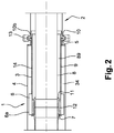
- Fig. 2 shows the plug-in coupling in the assembled state.
- the two flanges 5, 10 are connected to a tensioning chain 13.
- another clamping of the flanges 5, 10, for example a clamp can also be used.
- the flanges 5, 10 provided with holes and connected with screws or bolts.
- the sealing ring 12 shrinks due to the low temperature at the cold end of the coupling 1 on the two receiving parts 7, 11 and thus seals the ring gap 14 located between the coupling plug 2 and the coupling socket 1 with respect to the interior of the cryogenic line.
- a C-ring seal is used, it must be biased by a force acting continuously in the longitudinal axial direction force. At the opposite end of the annular gap 14 is also sealed by the sealing ring 10b.
- the reservoir 6 forms an extension of the annular gap 14 between the two coupling elements 1, 2 at the cold end of the coupling plug.
- condensed fluid for example, air or cryogenic medium
- the liquid is thus prevented from flowing to the warm end.
- the reservoir 6 is designed so that all the condensed liquid can be held therein. For example, this takes into account the volume of air present in the annular gap during assembly of the coupling and the resulting volume of liquid.
- the volume ratio between gaseous air and liquid air is approximately 750. For an air volume of, for example, 1500 ml, the reservoir 6 can therefore absorb about 2 ml of liquid.
- an inner diameter of the female part 1 of about 150 mm and an inner length of the Johnston coupling including the length of the reservoir 6 of about 800 mm, for example, an inner diameter of the Reservoirs 6 of approximately 154 mm and a length of the reservoir of approximately 50 mm, so that 2 ml of condensate can be absorbed.
- Inner tube diameter of 20 mm or 50 mm of the cryogenic lines to be connected this means, for example, that the reservoir 6 has a diameter about 2-4 mm larger than the inner tube piece 3 and extends about 5-20 mm along the coupling.
- the expanded diameter ring portion 6 advantageously has a length selected so that the reservoir 6 does not extend into the warm region of the coupling 1 so that the liquid accumulated in the reservoir 6 does not evaporate.
- the reservoir has a bottom 6a, which is flat in longitudinal section, so that the reservoir 6 is arranged concentrically relative to the remaining bush inner tube 3.
- the diameter of the reservoir 6 is constant over the entire ring section.
- the bottom of the reservoir may also have a concave shape or a conical, extended to the cold end shape (each seen in longitudinal section).
- the invention is applicable, for example, to the connection of conduits for the transport of cryogenic media or to the connection between a superconducting cable system and an end termination.
- a particularly preferred area of application is the connection of horizontal transport lines of cryogenic media.
Landscapes
- Engineering & Computer Science (AREA)
- General Engineering & Computer Science (AREA)
- Mechanical Engineering (AREA)
- Thermal Insulation (AREA)
- Joints With Sleeves (AREA)
- Quick-Acting Or Multi-Walled Pipe Joints (AREA)
Description
- Die Erfindung bezieht sich auf eine Steckkupplung für Kryoleitungen mit einer Kupplungsbuchse und einem Kupplungsstecker gemäß dem Oberbegriff des Patentanspruch 1.
- Eine solche Steckkupplung geht beispielsweise aus der
EP 1 957 851 B1 hervor. - Die Kupplungsbuchse und der Kupplungsstecker einer solchen Steckkupplung sind an einem Ende durch eine Flanschverbindung lösbar miteinander verbunden. Dieses Ende wird als "warmes" Ende bezeichnet, weil dieser Bereich im wesentlichen von der Umgebungstemperatur beeinflußt wird. Das Ende des Kupplungssteckers, das am weitesten in die Kupplungsbuchse hineinragt, wird als "kaltes" Ende bezeichnet. Ein Ringspalt zwischen den Kupplungselementen ist am "kalten" Ende durch eine Ringdichtung und am "warmen" Ende durch eine im Bereich der Flanschverbindung befindliche Ringdichtung abgedichtet. Eine derartige Kupplung wird auch als Johnston-Kupplung bezeichnet.
- Johnston-Kupplungen werden allgemein in vakuumisolierten Leitungssystemen eingesetzt, welche zum Transport von kryogenen Medien verwendet werden. Die Elemente der Kupplung sind zweckmäßigerweise doppelwandig und vakuumisoliert ausgebildet. Dadurch wird eine größere räumliche Entfernung zwischen der Verbindungsstelle der beiden äußeren Kupplungselemente und der Stelle, an welcher der Übertritt des kryogenen Mediums von der einen in die andere Leitung erfolgt, geschaffen. Durch diese relativ große Entfernung zwischen dem "warmen" und "kalten" Ende der Kupplung soll die Wärmelast von Normal- zu kryogener Temperatur reduziert werden. Eine Vereisung der Kupplungsstelle und Verluste des kryogenen Mediums durch Verdampfung sollen dadurch verringert werden.
- Bei einer solchen Kupplung wird der Kupplungsstecker auch als "Male-Teil" und die dazugehörige Kupplungsbuchse auch als "Female-Teil" bezeichnet.
- Aus der eingangs erwähnten
EP 1 957 851 B1 ist eine Steckkupplung für vakuumisolierte Leitungen nach Art einer Johnston-Kupplung bekannt. Eine vergleichbare Steckkupplung geht aus derJP S53 6923 U - In horizontalen oder annähernd horizontalen Kupplungsanordnungen können die am kalten Ende im Ringspalt durch Kondensation gebildeten Flüssigkeiten zum warmen Ende fließen, wo sie verdampft werden. Der Dampf gelangt wiederum zum kalten Ende, wo er erneut kondensiert. Dieser Kreislauf der ständigen Phasenwechsel ist mit permanent eingebrachter und abgegebener latenter Wärme verbunden, was wiederum zu einem sehr großen thermischen Austausch mit der Umgebung und damit zum Vereisen der Außenseite der Kupplung führen kann. Dieser Effekt wird auch Wärmerohreffekt genannt. In vertikalen und bis zu etwa 45° geneigten Kupplungen treten diese unerwünschten Effekte nicht auf.
- Der vorliegenden Erfindung liegt die Aufgabe zugrunde, eine lösbare Steckkupplung für Kryoleitungen bereitzustellen, die sich durch extrem geringe Verluste auszeichnet. Insbesondere sollen das Entstehen des Wärmerohreffekts und das Vereisen von Steckkupplungen verhindert werden.
- Diese Aufgabe wird entsprechend dem kennzeichnenden Merkmal des Patentanspruchs 1 gelöst.
- Die erfindungsgemäße Steckkupplung ist derart ausgelegt, dass bei horizontaler oder nahezu horizontaler Anordnung das Kondensat der Luft, welche beim Zusammenbau der Steckkupplung vorhanden ist, in dem Reservoir am kalten Ende der Kupplung gehalten wird. Das Kondensat kann somit nicht zum warmen Ende fließen und dort verdunsten, sodaß der Wärmerohreffekt verhindert wird. Dadurch können ein zu großer Wärmeaustausch mit der Umgebung und ein äußeres Vereisen der Kupplung vermieden werden. Das Reservoir ist so gestaltet, dass das gesamte kondensierte Fluid darin gehalten werden kann. Die Größe des Reservoirs ist demnach dem Volumen des Ringspaltes zwischen den Kupplungselementen angepaßt. Es ist deshalb auch möglich, Kupplungen mit größeren Ringspalten, die für bestimmte Anwendungen notwendig sind, vorzusehen, ohne dass die Kupplung durch den Wärmerohreffekt beeinträchtigt wird. Durch die Dichtungen am warmen und am kalten Ende der Steckkupplung wird das Eindringen von kryogener Flüssigkeit, Dampf oder Luft in den Ringspalt weitestgehend verhindert. Sollte dennoch kryogene Flüssigkeit durch eine defekte Dichtung am kalten Ende der Steckkupplung in den Ringspalt eindringen, so wird auch diese, zusätzlich zu dem Kondensat der Luft, in dem Reservoir gehalten und daran gehindert, zum warmen Ende der Kupplung zu fließen.
- Weitere vorteilhafte Ausgestaltungen der Erfindung sind in den Unteransprüchen erfaßt.
- Ausführungsbeispiele des Erfindungsgegenstandes sind in den Zeichnungen dargestellt.
- Es zeigen:
-
Fig. 1 den Kupplungsstecker und die Kupplungsbuchse der erfindungsgemäßen Steckkupplung nach einer Ausführungsform vor dem Zusammenbau. -
Fig. 2 die Steckkupplung in montiertem Zustand. - In den Zeichnungen beziehen sich gleiche Bezugszeichen auf gleiche technische Merkmale.
- In
Fig. 1 sind die beiden Kupplungselemente 1, 2 vor dem Zusammenbau dargestellt. Das Bezugszeichen 1 bezieht sich auf die Kupplungsbuchse bzw. das Female-Teil, wogegen das Bezugszeichen 2 auf den Kupplungsstecker bzw. das Male-Teil hinweist. - Die Kupplungsbuchse bzw. -dose 1 besteht aus einem inneren Rohrstück 3 und einem äußeren Rohrstück 4. Das innere und das äußere Rohrstück 3, 4 sind an ihrem Ende mit einem Flansch 5 vakuumdicht verschweißt. Der Innendurchmesser der Bohrung des Flansches 5 entspricht dem Innendurchmesser des inneren Rohrstücks 3. Die dem Flansch 5 abgekehrten Enden der Rohrstücke 3, 4 sind mit dem Innenrohr bzw. dem Außenrohr einer Kryoleitung bzw. einem Zuführstutzen einer Kühlanlage für das kryogene Medium vakuumdicht verschweißt (nicht dargestellt). Zwischen dem inneren Rohrstück 3 und dem äußeren Rohrstück 4 besteht ein evakuierter Ringspalt 34. Dieser Ringraum 34 ist mit dem evakuierten Raum der Kryoleitung verbunden bzw. endseitig abgeschottet.
- Das innere Rohrstück 3 der Kupplungsbuchse 1 weist an ihrem dem Flansch abgekehrten Ende einen Bereich 6 mit einem gegenüber dem Rohrinnendurchmesser erweiterten Durchmesser auf. Dieser erweiterte Ringabschnitt 6 bildet ein Reservoir 6. Das Reservoir 6 hat an seinem dem Flansch 5 abgekehrten Ende ein Aufnahmeteil 7. Das Aufnahmeteil 7 ist ein Drehteil, welches den Übergang zwischen dem erweiterten Bereich 6 und der Kryoleitung bzw. dem Zuführstutzen bewirkt. Das Aufnahmeteil 7 hat einen in die Kupplungsbuchse 1 hineinragenden Vorsprung, welcher mit dem Ende des Kupplungssteckers 2 zusammenwirkt.
- Der Kupplungsstecker 2 besteht aus einem inneren Rohrstück 8 und einem äußeren Rohrstück 9. Zwischen den Rohrstücken 8, 9 besteht ein evakuierter Ringspalt 89. Dieser evakuierte Ringraum 89 ist ebenfalls mit dem evakuierten Ringraum der Kryoleitung verbunden (nicht dargestellt).
- Der innere Durchmesser des inneren Rohrstücks 3 der Kupplungsbuchse 1 ist geringfügig größer als der äußere Durchmesser des äußeren Rohrstücks 9 des Kupplungssteckers 2.
- Ein Flansch 10 ist mit einem Ende des äußeren Rohrstücks 9 des Male-Teils 2 bzw. Kupplungssteckers vakuumdicht verschweißt. Die dem Flansch 10 abgekehrten Enden des inneren Rohrstücks 8 und des äußeren Rohrstücks 9 sind jeweils mit einem Aufnahmeteil 11 vakuumdicht verschweißt. Das Aufnahmeteil 11 weist einen rohrförmigen Vorsprung 11a auf, auf welchem ein Dichtring 12 angeordnet ist. Der Dichtring 12 kann beispielsweise aus PTFE bestehen. Anstatt eines PTFE-Dichtrings kann auch eine C-Ring-Dichtung zum Einsatz kommen.
- Der Flansch 10 weist eine um die Flanschfläche umlaufende Ringnut 10a mit einem darin befindlichen Dichtring 10b auf. Der Flansch 10 hat außerdem einen rohrförmigen Ansatz 10c. Der Flansch 5 der Kupplungsbuchse 1 zeigt in seiner inneren Bohrung eine Durchmessererweiterung 5a, in welche der rohrförmige Ansatz 10c des Flansches 10 einführbar ist. Durch den Einsatz des Ansatzes 10c in die Durchmessererweiterung 5a werden die beiden Kupplungsteile 1, 2 beim Zusammenbau zueinander zentriert.
-
Fig. 2 zeigt die Steckkupplung im montierten Zustand. Die beiden Flansche 5, 10 sind mit einer Spannkette 13 verbunden. Anstatt der dargestellten Spannkette 13 kann auch eine andere Verklammerung der Flansche 5, 10, beispielsweise eine Schelle, verwendet werden. Alternativ können die Flansche 5, 10 mit Bohrungen versehen und mit Schrauben oder Bolzen verbunden werden. Der Dichtring 12 schrumpft durch die tiefe Temperatur am kalten Ende der Kupplung 1 auf die beiden Aufnahmeteile 7, 11 auf und dichtet damit den zwischen dem Kupplungsstecker 2 und der Kupplungsdose 1 befindlichen Ringspalt 14 gegenüber dem Innenraum der Kryoleitung ab. Falls anstatt des dargestellten Dichtrings 12 eine C-Ring-Dichtung verwendet wird, so muss diese durch eine ständig in längsaxialer Richtung wirkende Kraft vorgespannt werden. Am entgegengesetzten Ende ist der Ringspalt 14 ebenfalls durch den Dichtring 10b abgedichtet. - Im montierten Zustand bildet das Reservoir 6 eine Erweiterung des Ringspaltes 14 zwischen den beiden Kupplungselementen 1, 2 am kalten Ende des Kupplungssteckers. In dem Ringspalt 14 kondensiertes Fluid (beispielsweise Luft oder kryogenes Medium) kann, bei einer horizontal angeordneten Steckkupplung, in dem Reservoir 6 am kalten Ende der Kupplung gehalten werden. Die Flüssigkeit wird somit davon abgehalten, zu dem warmen Ende zu fließen. Das Reservoir 6 ist so ausgeführt, dass die gesamte kondensierte Flüssigkeit darin gehalten werden kann. Dafür wird beispielsweise das Luftvolumen, das während des Zusammenbaus der Kupplung in dem Ringspalt vorhanden ist, und das daraus resultierende Flüssigkeitsvolumen berücksichtigt. Das Volumenverhältnis zwischen gasförmiger Luft und flüssiger Luft ist annähernd 750. Für ein Luftvolumen von beispielsweise 1500 ml muss das Reservoir 6 demnach rund 2 ml Flüssigkeit aufnehmen können. Für einen Außendurchmesser des Male-Teils 2 von ca. 142 mm, einen Innendurchmesser des Female-Teils 1 von etwa 150 mm und eine innere Länge der Johnston-Kupplung einschließlich der Länge des Reservoirs 6 von etwa 800 mm, ergeben sich beispielsweise ein Innendurchmesser des Reservoirs 6 von ca. 154 mm und eine Länge des Reservoirs von ca. 50 mm, damit 2 ml Kondensat aufgenommen werden können. Innenrohrdurchmesser von 20 mm oder 50 mm der zu verbindenden Kryoleitungen bedeutet dies beispielsweise, dass das Reservoir 6 einen etwa 2-4 mm größeren Durchmesser als innere Rohrstück 3 hat und sich etwa 5-20 mm entlang der Kupplung erstreckt. Der Ringabschnitt 6 mit dem erweiterten Durchmesser hat vorteilhafterweise eine Länge, die so gewählt ist, dass sich das Reservoir 6 nicht bis in den warmen Bereich der Kupplung 1 erstreckt, damit die Flüssigkeit, die sich im Reservoir 6 angesammelt hat, nicht verdampft.
- In der in den
Fig. 1 und2 dargestellten Ausführungsform hat das Reservoir einen Boden 6a, der im Längsschnitt gesehen eben ist, sodass das Reservoir 6 relativ zu dem restlichen Buchseninnenrohr 3 konzentrisch angeordnet ist. Der Durchmesser des Reservoirs 6 ist über den gesamten Ringabschnitt konstant. Nach anderen, nicht dargestellten Ausführungsformen kann der Boden des Reservoirs auch eine konkave Form oder eine konische, zum kalten Ende hin erweiterte Form haben (jeweils im Längsschnitt gesehen). - Die Erfindung ist beispielsweise anwendbar zur Verbindung von Leitungsrohren zum Transport von kryogenen Medien oder zur Verbindung zwischen einem Supraleiterkabelsystem und einem Endenabschluß. Ein besonders bevorzugter Anwendungsbereich ist die Verbindung von horizontalen Transportleitungen von kryogenen Medien.
Claims (5)
- Steckkupplung für Kryoleitungen mit einer Kupplungsbuchse (1) und einem Kupplungsstecker (2), zur Verwendung in horizontalen oder annähernd horizontalen Kupplungsanordnungen, bei welcher die Kupplungsbuchse (1) und der Kupplungsstecker (2) jeweils aus einem inneren Rohrstück (3,8) und einem äußeren Rohrstück (4,9) bestehen, wobei die Kupplungsbuchse (1) und der Kupplungsstecker (2) durch eine an ihrem als "warmes" Ende bezeichneten Ende befindliche Flanschverbindung (5,10) lösbar miteinander verbunden sind, bei welcher an einem anderen, als "kaltes" Ende bezeichnete Ende ein zwischen der Kupplungsbuchse (1) und dem Kupplungsstecker (2) vorhandener Ringspalt (14) durch eine Ringdichtung (12) abgedichtet ist und bei welcher das "warme" Ende durch eine im Bereich der Flanschverbindung (5,10) befindliche Ringdichtung (10b) abgedichtet ist, dadurch gekennzeichnet, dass die Kupplungsbuchse (1) am "kalten" Ende ein Reservoir (6) aufweist, welches durch einen Ringabschnitt (6) mit einem gegenüber dem Durchmesser des inneren Rohrstücks (3) der Kupplungsbuchse (1) aufgeweiteten Durchmesser gebildet ist, so dass eine Erweiterung des Ringspaltes (14) gebildet wird.
- Steckkupplung nach Anspruch 1, dadurch gekennzeichnet, dass das Reservoir (6) einen im Längsschnitt ebenen Boden (6a) aufweist, sodass das Reservoir (6) relativ zu dem restlichen inneren Rohrstück (3) konzentrisch angeordnet ist.
- Steckkupplung nach Anspruch 1 oder 2, dadurch gekennzeichnet, dass der Ringabschnitt (6) einen konstanten Durchmesser hat.
- Steckkupplung nach Anspruch 1 oder 2, dadurch gekennzeichnet, dass das Reservoir (6) einen im Längsschnitt konkaven Boden aufweist.
- Steckkupplung nach Anspruch 1 oder 2, dadurch gekennzeichnet, dass der Boden des Reservoirs (6) eine im Längsschnitt konische, zum "kalten" Ende hin erweiterte Form aufweist.
Priority Applications (2)
| Application Number | Priority Date | Filing Date | Title |
|---|---|---|---|
| EP16306805.9A EP3339713B1 (de) | 2016-12-23 | 2016-12-23 | Steckkupplung fuer kryoleitungen |
| JP2017246633A JP7077009B2 (ja) | 2016-12-23 | 2017-12-22 | 極低温管路用プラグイン式継手 |
Applications Claiming Priority (1)
| Application Number | Priority Date | Filing Date | Title |
|---|---|---|---|
| EP16306805.9A EP3339713B1 (de) | 2016-12-23 | 2016-12-23 | Steckkupplung fuer kryoleitungen |
Publications (2)
| Publication Number | Publication Date |
|---|---|
| EP3339713A1 EP3339713A1 (de) | 2018-06-27 |
| EP3339713B1 true EP3339713B1 (de) | 2019-10-16 |
Family
ID=57749796
Family Applications (1)
| Application Number | Title | Priority Date | Filing Date |
|---|---|---|---|
| EP16306805.9A Active EP3339713B1 (de) | 2016-12-23 | 2016-12-23 | Steckkupplung fuer kryoleitungen |
Country Status (2)
| Country | Link |
|---|---|
| EP (1) | EP3339713B1 (de) |
| JP (1) | JP7077009B2 (de) |
Families Citing this family (2)
| Publication number | Priority date | Publication date | Assignee | Title |
|---|---|---|---|---|
| EP3851724B1 (de) * | 2020-01-20 | 2022-08-10 | Nexans | Johnston-kupplung mit galvanischer trennung |
| PL4417853T3 (pl) * | 2023-02-15 | 2026-03-16 | Nexans | Złączka do wielościennych przewodów |
Family Cites Families (9)
| Publication number | Priority date | Publication date | Assignee | Title |
|---|---|---|---|---|
| JPS536923U (de) * | 1976-07-03 | 1978-01-21 | ||
| JPS5852396U (ja) * | 1981-10-03 | 1983-04-09 | 大同酸素株式会社 | バイオネツト継手 |
| JPS5965696A (ja) * | 1982-10-04 | 1984-04-13 | 株式会社日立製作所 | 極低温配管のバイオネツト継手 |
| JP2911094B2 (ja) * | 1994-01-28 | 1999-06-23 | 象印マホービン株式会社 | 真空2重管の継手構造 |
| JP3669665B2 (ja) * | 1997-09-29 | 2005-07-13 | エア・ウォーター株式会社 | 空気分離装置 |
| JP3629677B2 (ja) * | 1999-05-10 | 2005-03-16 | 住友重機械工業株式会社 | 低温流体用バイヨネット継ぎ手 |
| JP2006038223A (ja) * | 2004-07-20 | 2006-02-09 | Chart Industries Inc | パイプ装置のためのシール |
| DE102005059089A1 (de) | 2005-12-10 | 2007-06-14 | Nexans | Steckkupplung für Kryoleitungen |
| JP6396264B2 (ja) * | 2015-07-10 | 2018-09-26 | 東京貿易エンジニアリング株式会社 | 液体水素用流体荷役装置 |
-
2016
- 2016-12-23 EP EP16306805.9A patent/EP3339713B1/de active Active
-
2017
- 2017-12-22 JP JP2017246633A patent/JP7077009B2/ja active Active
Non-Patent Citations (1)
| Title |
|---|
| None * |
Also Published As
| Publication number | Publication date |
|---|---|
| JP2018115763A (ja) | 2018-07-26 |
| JP7077009B2 (ja) | 2022-05-30 |
| EP3339713A1 (de) | 2018-06-27 |
Similar Documents
| Publication | Publication Date | Title |
|---|---|---|
| EP1957851B1 (de) | Steckkupplung für kryoleitungen | |
| EP2257726B1 (de) | Hochdruckverschraubung | |
| EP2828566B1 (de) | Kupplung zum anschluss fluidführender leitungen | |
| EP2946134B1 (de) | Nottrennkupplung | |
| EP4407224A2 (de) | Hydraulikleitungskupplung, insbesondere für eine hydraulische bremse oder kupplung lenkergeführter fahrzeuge | |
| EP2890923B1 (de) | Rohrverbindung zur durchleitung eines unter druck stehenden fluids | |
| EP2986882B1 (de) | Rohrverbindung zur durchleitung eines unter druck stehenden fluids | |
| EP3339713B1 (de) | Steckkupplung fuer kryoleitungen | |
| EP4235001B1 (de) | Thermisch isolierte transferleitung mit kuppelelement | |
| DE102009057954A1 (de) | Anschlusseinrichtung für einen Koaxialrohr-Wärmetauscher | |
| EP3746692B1 (de) | Wasserleitung mit rohrfitting | |
| EP3408574B1 (de) | Kupplungskörper für eine steckverbindung von rohrleitungen, insbesondere kunststoffrohrleitungen | |
| EP2199652B1 (de) | Vorrichtung zum dichten Verbinden und zur Befestigung einer Fluidleitung mit einem anderen fluidführenden Bauteil | |
| DE3142702A1 (de) | "anordnung zum verbinden von zwei leitungsrohren bzw. zum anschluss eines leitungsrohres an eine armatur, einen behaelter etc." | |
| DE102006024122B4 (de) | Vorrichtung zur Verbindung zweier Sammelrohre bei Kollektoren für Solaranlagen | |
| EP4141308B1 (de) | Rohrverbindungsanordnung | |
| DE102015209124A1 (de) | Kupplungsstecker, Kupplungsdose und Kupplung für kryogene Medien | |
| EP2963323B1 (de) | Verwendung eines Rohrleitungsverbinders zum Führen von Wasserstoffgas sowie Rohrleitungsverbinder mit Wasserstoffgas | |
| EP1756463A1 (de) | Drehdurchführung mit einer gasrückführung | |
| AT511321B1 (de) | Sonnenkollektor | |
| DE10013468C1 (de) | Steckkupplungsverbindung für ein fluidführendes Rohr und Verfahren zum Ausbilden eines Anschlussendes eines Rohres als Steckelement einer Steckkupplungsverbindung | |
| DE10126210B4 (de) | Lösbare Kupplung für Rohrleitungen | |
| DE102016223744B4 (de) | Bremssystem mit einem Verbindungselement | |
| DE202012013363U1 (de) | Steckverbinder zur Verbindung zweier mediumführender Elemente sowie Rohrleitungssystem mit mindestens zwei mediumführenden Elementen | |
| EP2458173A1 (de) | Ventilanordnung |
Legal Events
| Date | Code | Title | Description |
|---|---|---|---|
| PUAI | Public reference made under article 153(3) epc to a published international application that has entered the european phase |
Free format text: ORIGINAL CODE: 0009012 |
|
| STAA | Information on the status of an ep patent application or granted ep patent |
Free format text: STATUS: REQUEST FOR EXAMINATION WAS MADE |
|
| 17P | Request for examination filed |
Effective date: 20170926 |
|
| AK | Designated contracting states |
Kind code of ref document: A1 Designated state(s): AL AT BE BG CH CY CZ DE DK EE ES FI FR GB GR HR HU IE IS IT LI LT LU LV MC MK MT NL NO PL PT RO RS SE SI SK SM TR |
|
| AX | Request for extension of the european patent |
Extension state: BA ME |
|
| GRAP | Despatch of communication of intention to grant a patent |
Free format text: ORIGINAL CODE: EPIDOSNIGR1 |
|
| STAA | Information on the status of an ep patent application or granted ep patent |
Free format text: STATUS: GRANT OF PATENT IS INTENDED |
|
| INTG | Intention to grant announced |
Effective date: 20190510 |
|
| GRAS | Grant fee paid |
Free format text: ORIGINAL CODE: EPIDOSNIGR3 |
|
| GRAA | (expected) grant |
Free format text: ORIGINAL CODE: 0009210 |
|
| STAA | Information on the status of an ep patent application or granted ep patent |
Free format text: STATUS: THE PATENT HAS BEEN GRANTED |
|
| AK | Designated contracting states |
Kind code of ref document: B1 Designated state(s): AL AT BE BG CH CY CZ DE DK EE ES FI FR GB GR HR HU IE IS IT LI LT LU LV MC MK MT NL NO PL PT RO RS SE SI SK SM TR |
|
| REG | Reference to a national code |
Ref country code: GB Ref legal event code: FG4D Free format text: NOT ENGLISH |
|
| REG | Reference to a national code |
Ref country code: CH Ref legal event code: EP |
|
| REG | Reference to a national code |
Ref country code: DE Ref legal event code: R096 Ref document number: 502016007106 Country of ref document: DE |
|
| REG | Reference to a national code |
Ref country code: IE Ref legal event code: FG4D Free format text: LANGUAGE OF EP DOCUMENT: GERMAN |
|
| REG | Reference to a national code |
Ref country code: AT Ref legal event code: REF Ref document number: 1191617 Country of ref document: AT Kind code of ref document: T Effective date: 20191115 |
|
| REG | Reference to a national code |
Ref country code: NL Ref legal event code: FP |
|
| REG | Reference to a national code |
Ref country code: LT Ref legal event code: MG4D |
|
| PG25 | Lapsed in a contracting state [announced via postgrant information from national office to epo] |
Ref country code: SE Free format text: LAPSE BECAUSE OF FAILURE TO SUBMIT A TRANSLATION OF THE DESCRIPTION OR TO PAY THE FEE WITHIN THE PRESCRIBED TIME-LIMIT Effective date: 20191016 Ref country code: LV Free format text: LAPSE BECAUSE OF FAILURE TO SUBMIT A TRANSLATION OF THE DESCRIPTION OR TO PAY THE FEE WITHIN THE PRESCRIBED TIME-LIMIT Effective date: 20191016 Ref country code: PL Free format text: LAPSE BECAUSE OF FAILURE TO SUBMIT A TRANSLATION OF THE DESCRIPTION OR TO PAY THE FEE WITHIN THE PRESCRIBED TIME-LIMIT Effective date: 20191016 Ref country code: NO Free format text: LAPSE BECAUSE OF FAILURE TO SUBMIT A TRANSLATION OF THE DESCRIPTION OR TO PAY THE FEE WITHIN THE PRESCRIBED TIME-LIMIT Effective date: 20200116 Ref country code: GR Free format text: LAPSE BECAUSE OF FAILURE TO SUBMIT A TRANSLATION OF THE DESCRIPTION OR TO PAY THE FEE WITHIN THE PRESCRIBED TIME-LIMIT Effective date: 20200117 Ref country code: LT Free format text: LAPSE BECAUSE OF FAILURE TO SUBMIT A TRANSLATION OF THE DESCRIPTION OR TO PAY THE FEE WITHIN THE PRESCRIBED TIME-LIMIT Effective date: 20191016 Ref country code: PT Free format text: LAPSE BECAUSE OF FAILURE TO SUBMIT A TRANSLATION OF THE DESCRIPTION OR TO PAY THE FEE WITHIN THE PRESCRIBED TIME-LIMIT Effective date: 20200217 Ref country code: FI Free format text: LAPSE BECAUSE OF FAILURE TO SUBMIT A TRANSLATION OF THE DESCRIPTION OR TO PAY THE FEE WITHIN THE PRESCRIBED TIME-LIMIT Effective date: 20191016 Ref country code: BG Free format text: LAPSE BECAUSE OF FAILURE TO SUBMIT A TRANSLATION OF THE DESCRIPTION OR TO PAY THE FEE WITHIN THE PRESCRIBED TIME-LIMIT Effective date: 20200116 |
|
| PG25 | Lapsed in a contracting state [announced via postgrant information from national office to epo] |
Ref country code: HR Free format text: LAPSE BECAUSE OF FAILURE TO SUBMIT A TRANSLATION OF THE DESCRIPTION OR TO PAY THE FEE WITHIN THE PRESCRIBED TIME-LIMIT Effective date: 20191016 Ref country code: IS Free format text: LAPSE BECAUSE OF FAILURE TO SUBMIT A TRANSLATION OF THE DESCRIPTION OR TO PAY THE FEE WITHIN THE PRESCRIBED TIME-LIMIT Effective date: 20200224 Ref country code: RS Free format text: LAPSE BECAUSE OF FAILURE TO SUBMIT A TRANSLATION OF THE DESCRIPTION OR TO PAY THE FEE WITHIN THE PRESCRIBED TIME-LIMIT Effective date: 20191016 |
|
| PG25 | Lapsed in a contracting state [announced via postgrant information from national office to epo] |
Ref country code: AL Free format text: LAPSE BECAUSE OF FAILURE TO SUBMIT A TRANSLATION OF THE DESCRIPTION OR TO PAY THE FEE WITHIN THE PRESCRIBED TIME-LIMIT Effective date: 20191016 |
|
| REG | Reference to a national code |
Ref country code: DE Ref legal event code: R097 Ref document number: 502016007106 Country of ref document: DE |
|
| PG2D | Information on lapse in contracting state deleted |
Ref country code: IS |
|
| PG25 | Lapsed in a contracting state [announced via postgrant information from national office to epo] |
Ref country code: CZ Free format text: LAPSE BECAUSE OF FAILURE TO SUBMIT A TRANSLATION OF THE DESCRIPTION OR TO PAY THE FEE WITHIN THE PRESCRIBED TIME-LIMIT Effective date: 20191016 Ref country code: EE Free format text: LAPSE BECAUSE OF FAILURE TO SUBMIT A TRANSLATION OF THE DESCRIPTION OR TO PAY THE FEE WITHIN THE PRESCRIBED TIME-LIMIT Effective date: 20191016 Ref country code: DK Free format text: LAPSE BECAUSE OF FAILURE TO SUBMIT A TRANSLATION OF THE DESCRIPTION OR TO PAY THE FEE WITHIN THE PRESCRIBED TIME-LIMIT Effective date: 20191016 Ref country code: ES Free format text: LAPSE BECAUSE OF FAILURE TO SUBMIT A TRANSLATION OF THE DESCRIPTION OR TO PAY THE FEE WITHIN THE PRESCRIBED TIME-LIMIT Effective date: 20191016 Ref country code: RO Free format text: LAPSE BECAUSE OF FAILURE TO SUBMIT A TRANSLATION OF THE DESCRIPTION OR TO PAY THE FEE WITHIN THE PRESCRIBED TIME-LIMIT Effective date: 20191016 Ref country code: IS Free format text: LAPSE BECAUSE OF FAILURE TO SUBMIT A TRANSLATION OF THE DESCRIPTION OR TO PAY THE FEE WITHIN THE PRESCRIBED TIME-LIMIT Effective date: 20200216 |
|
| REG | Reference to a national code |
Ref country code: CH Ref legal event code: PL |
|
| PLBE | No opposition filed within time limit |
Free format text: ORIGINAL CODE: 0009261 |
|
| STAA | Information on the status of an ep patent application or granted ep patent |
Free format text: STATUS: NO OPPOSITION FILED WITHIN TIME LIMIT |
|
| REG | Reference to a national code |
Ref country code: BE Ref legal event code: MM Effective date: 20191231 |
|
| PG25 | Lapsed in a contracting state [announced via postgrant information from national office to epo] |
Ref country code: IT Free format text: LAPSE BECAUSE OF FAILURE TO SUBMIT A TRANSLATION OF THE DESCRIPTION OR TO PAY THE FEE WITHIN THE PRESCRIBED TIME-LIMIT Effective date: 20191016 Ref country code: MC Free format text: LAPSE BECAUSE OF FAILURE TO SUBMIT A TRANSLATION OF THE DESCRIPTION OR TO PAY THE FEE WITHIN THE PRESCRIBED TIME-LIMIT Effective date: 20191016 Ref country code: SK Free format text: LAPSE BECAUSE OF FAILURE TO SUBMIT A TRANSLATION OF THE DESCRIPTION OR TO PAY THE FEE WITHIN THE PRESCRIBED TIME-LIMIT Effective date: 20191016 Ref country code: SM Free format text: LAPSE BECAUSE OF FAILURE TO SUBMIT A TRANSLATION OF THE DESCRIPTION OR TO PAY THE FEE WITHIN THE PRESCRIBED TIME-LIMIT Effective date: 20191016 |
|
| 26N | No opposition filed |
Effective date: 20200717 |
|
| PG25 | Lapsed in a contracting state [announced via postgrant information from national office to epo] |
Ref country code: FR Free format text: LAPSE BECAUSE OF NON-PAYMENT OF DUE FEES Effective date: 20191231 Ref country code: LU Free format text: LAPSE BECAUSE OF NON-PAYMENT OF DUE FEES Effective date: 20191223 Ref country code: IE Free format text: LAPSE BECAUSE OF NON-PAYMENT OF DUE FEES Effective date: 20191223 |
|
| PG25 | Lapsed in a contracting state [announced via postgrant information from national office to epo] |
Ref country code: SI Free format text: LAPSE BECAUSE OF FAILURE TO SUBMIT A TRANSLATION OF THE DESCRIPTION OR TO PAY THE FEE WITHIN THE PRESCRIBED TIME-LIMIT Effective date: 20191016 Ref country code: LI Free format text: LAPSE BECAUSE OF NON-PAYMENT OF DUE FEES Effective date: 20191231 Ref country code: CH Free format text: LAPSE BECAUSE OF NON-PAYMENT OF DUE FEES Effective date: 20191231 Ref country code: BE Free format text: LAPSE BECAUSE OF NON-PAYMENT OF DUE FEES Effective date: 20191231 |
|
| PG25 | Lapsed in a contracting state [announced via postgrant information from national office to epo] |
Ref country code: CY Free format text: LAPSE BECAUSE OF FAILURE TO SUBMIT A TRANSLATION OF THE DESCRIPTION OR TO PAY THE FEE WITHIN THE PRESCRIBED TIME-LIMIT Effective date: 20191016 |
|
| PG25 | Lapsed in a contracting state [announced via postgrant information from national office to epo] |
Ref country code: HU Free format text: LAPSE BECAUSE OF FAILURE TO SUBMIT A TRANSLATION OF THE DESCRIPTION OR TO PAY THE FEE WITHIN THE PRESCRIBED TIME-LIMIT; INVALID AB INITIO Effective date: 20161223 Ref country code: MT Free format text: LAPSE BECAUSE OF FAILURE TO SUBMIT A TRANSLATION OF THE DESCRIPTION OR TO PAY THE FEE WITHIN THE PRESCRIBED TIME-LIMIT Effective date: 20191016 |
|
| GBPC | Gb: european patent ceased through non-payment of renewal fee |
Effective date: 20201223 |
|
| PG25 | Lapsed in a contracting state [announced via postgrant information from national office to epo] |
Ref country code: GB Free format text: LAPSE BECAUSE OF NON-PAYMENT OF DUE FEES Effective date: 20201223 |
|
| PG25 | Lapsed in a contracting state [announced via postgrant information from national office to epo] |
Ref country code: TR Free format text: LAPSE BECAUSE OF FAILURE TO SUBMIT A TRANSLATION OF THE DESCRIPTION OR TO PAY THE FEE WITHIN THE PRESCRIBED TIME-LIMIT Effective date: 20191016 |
|
| PG25 | Lapsed in a contracting state [announced via postgrant information from national office to epo] |
Ref country code: MK Free format text: LAPSE BECAUSE OF FAILURE TO SUBMIT A TRANSLATION OF THE DESCRIPTION OR TO PAY THE FEE WITHIN THE PRESCRIBED TIME-LIMIT Effective date: 20191016 |
|
| REG | Reference to a national code |
Ref country code: AT Ref legal event code: MM01 Ref document number: 1191617 Country of ref document: AT Kind code of ref document: T Effective date: 20211223 |
|
| PG25 | Lapsed in a contracting state [announced via postgrant information from national office to epo] |
Ref country code: AT Free format text: LAPSE BECAUSE OF NON-PAYMENT OF DUE FEES Effective date: 20211223 |
|
| PGFP | Annual fee paid to national office [announced via postgrant information from national office to epo] |
Ref country code: DE Payment date: 20251211 Year of fee payment: 10 |
|
| PGFP | Annual fee paid to national office [announced via postgrant information from national office to epo] |
Ref country code: NL Payment date: 20251219 Year of fee payment: 10 |