EP3339512B1 - Vehicle retention system - Google Patents
Vehicle retention system Download PDFInfo
- Publication number
- EP3339512B1 EP3339512B1 EP16205576.8A EP16205576A EP3339512B1 EP 3339512 B1 EP3339512 B1 EP 3339512B1 EP 16205576 A EP16205576 A EP 16205576A EP 3339512 B1 EP3339512 B1 EP 3339512B1
- Authority
- EP
- European Patent Office
- Prior art keywords
- support
- retention system
- post
- console
- vehicle retention
- Prior art date
- Legal status (The legal status is an assumption and is not a legal conclusion. Google has not performed a legal analysis and makes no representation as to the accuracy of the status listed.)
- Active
Links
Images


Classifications
-
- E—FIXED CONSTRUCTIONS
- E01—CONSTRUCTION OF ROADS, RAILWAYS, OR BRIDGES
- E01F—ADDITIONAL WORK, SUCH AS EQUIPPING ROADS OR THE CONSTRUCTION OF PLATFORMS, HELICOPTER LANDING STAGES, SIGNS, SNOW FENCES, OR THE LIKE
- E01F15/00—Safety arrangements for slowing, redirecting or stopping errant vehicles, e.g. guard posts or bollards; Arrangements for reducing damage to roadside structures due to vehicular impact
- E01F15/14—Safety arrangements for slowing, redirecting or stopping errant vehicles, e.g. guard posts or bollards; Arrangements for reducing damage to roadside structures due to vehicular impact specially adapted for local protection, e.g. for bridge piers, for traffic islands
- E01F15/143—Protecting devices located at the ends of barriers
Definitions
- the invention relates to a arranged next to a carriageway F vehicle restraint system, with at least one held on posts, extending in the direction of travel spar, and having a spar-shaped, designed as a lowering initial and / or final construction.
- Such a vehicle restraint system is for lowering from the EP 2 927 373 A1 known.
- the training is to broaden the surface of the lowering of an approaching vehicle and stabilize this.
- This known doctrine can not fulfill the required task, since a vehicle running up to the lowering is lifted on one side of the vehicle on the upper edge of the plank of the lowering and the other side impinges intermittently only on the support arms arranged at a distance from the posts and thus in each case between successive support arms behind the spar falls.
- Another such vehicle restraint system is also from the EP 2 927 374 A1 known.
- the invention is therefore based on the object of specifying a generic vehicle restraint system, in which a colliding vehicle with four wheels undergoes stable continuous support.
- the support structure is fixed at its end facing the road surface directly or indirectly on the spar, the distance between the individual support structures regardless of the distance of the posts arbitrarily smaller or larger than that can be designed. As a result, the stable determination of the further device can be ensured.
- console is a support profile which extends in the longitudinal direction of the roadway and is fastened to the post, and the support structure rests directly or indirectly on a bearing area on the bracket. As a result, a stable support is provided.
- the support profile is a rigid profile, a base is fixed to the post. As a result, the torsional moment is introduced into the post and received by the post.
- the support profile is arranged offset away from the roadway backwards below the spar.
- the torque acting on the spar is favorably influenced, ie reduced.
- the sliding or supporting device may be part of a guide system for at least one displaceable energy absorbing element.
- a guide system for at least one displaceable energy absorbing element.
- the guide system may be arranged on the support structure so that at least a portion of the head surface remains free to allow subsequent adjustment (turning) of the post.
- this is a wall frame structure, which is fixed by means of one of the roadway facing frame portion on the spar and is supported by a lower frame portion on the console.
- the support structure is fastened to the spar by means of a wall section formed at its road-side end with the interposition of such a support bracket, as is also used for fixing the spar to a post.
- Fig. 1 a arranged next to a roadway vehicle restraint system 1 is shown with a trained as a lowering 4 start and / or end construction.
- the vehicle restraint system 1 has an extending in the direction of travel FR, assembled from several individual pieces spar 3, which is held on post 2, and support structures 5, which have a predetermined distance from each other.
- the support structure 5 is used in the illustrated embodiment, the support of energy-absorbing elements 10, of which 12 are arranged one behind the other in the example shown. However, depending on the design, more or less energy-absorbing elements may be provided. These elements absorb the kinetic energy of a vehicle that has strayed off the lane and is traveling up to the downslope 4. By this arrangement, it can be prevented that such a vehicle on the lowering as on a ski jump performs a long flight.
- Fig. 2 shows in a perspective schematic view of part of a lowering 4 of the vehicle restraint system Fig.1 in which a spar 3 is held on posts 2. Furthermore, a console 6 is attached to the post 2. The bracket 6 may additionally be held by means of one or more retaining tabs 6 'on the spar 3.
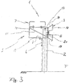
- Fig. 3 shows a view in the direction of travel on the vehicle restraint system 1 with support structure 5, spar 3, console 6 and sliding or support means 7.
- the support structure 5 is arranged so that it faces away from the carriageway F.
- Below the support structure 5 is at the back of the vehicle restraint system 1 to the post 2, a bracket 6 for supporting the support structure 5 arranged.
- the console 6 may be held on a stand-alone post assembly.
- the support structure 5 is provided with a support area 8 which rests on the console 6.
- the support structure 5 is located directly on the console 6; However, it may also be an intermediate layer between the bracket 6 and the support area 8 may be arranged, which largely prevents corrosion of the superimposed components.
- the arranged on the support structure 5, extending in the direction of travel slide or support means 7 can serve as a guideway for provided on the lowering traffic safety devices.
- this can be a form-locking guide which is formed by mutually opposite C-profiles, but a substantially planar guideway for safety devices is also possible.
- the bracket 6 is an L-shaped angle profile which extends in the longitudinal direction of the road F and is fastened below the beam 3 away from the roadway to the post and offset backwards.
- the sliding or supporting device 7 is in the illustrated example part of a mounting or guiding system for at least one displaceable energy absorbing element 10.
- a mounting or guiding system by one or more Guide rods / ropes can be ensured, which are guided through openings in the elements 10 (not shown).
- a leading over this post slide or support means 7 is offset laterally so far that a tool can be applied;
- the sliding or supporting device has a flat, plate-like shape. It may be provided at this point when using a plate web as a sliding or support means a recess.
- the support structure 5 is a wall frame structure 14.
- the stiffeners 15 shown in this example are not mandatory, but allow a stable and lightweight truss construction.
- the support structure 5 is fixed here by means of a roadway facing frame portion 16 on the spar 3 and supported by a lower frame portion 17 on the bracket 6.
- the spar 3 has on its side remote from the road on a support bracket 18 with an upper and a lower support wings 19 and a support wings both connecting abutting portion 20.
- the support structure 5 rests against the abutment portion 20 of the support bracket 18 of the beam 3 by means of a frame portion 16 formed at its roadside end and is fastened thereto.
- FIG. 4 shows a next embodiment of the support structure according to the invention 5.
- the support structure 5 a horizontally extending support arm 21 with a vertically downwardly projecting stop leg 22.
- a stiffener 23 is arranged in the angle between the support arm 21 and stop leg 22, wherein it has a lower peripheral edge, with which it rests on the console 6.
- a plate 24 may be provided to provide a wider support on the console 6.
- an additional reinforcement 25 may be arranged to increase the stability of the support structure 5.
- the support structure 5 is used in the illustrated embodiment, the inclusion of a rail assembly 25 in which the sliding or support means 7 is formed.
- traffic safety devices are added on the support structure 5 . These can be energy-consuming deformation bodies that deform plastically in the event of a collision of a vehicle and thereby convert the kinetic energy of the vehicle into deformation work.
- a support bracket 18 is also arranged in this embodiment, which rests with its abutment portion 20 on the stop leg 22 of the support structure 5 and is secured thereto.
- the invention is not limited in its execution to the above-mentioned preferred embodiments. Rather, a number of variants is conceivable, which makes use of the illustrated solution even with fundamentally different types of use.
Description
Die Erfindung betrifft ein neben einer Fahrbahn F angeordnetes Fahrzeugrückhaltesystem, mit mindestens einem an Pfosten gehaltenen, sich in Fahrtrichtung erstreckenden Holm, und mit einer den Holm aufweisenden, als Absenkung ausgebildeten Anfangs- und /oder Endkonstruktion.The invention relates to a arranged next to a carriageway F vehicle restraint system, with at least one held on posts, extending in the direction of travel spar, and having a spar-shaped, designed as a lowering initial and / or final construction.
Ein derartiges Fahrzeugrückhaltesystem ist für eine Absenkung aus der
Ein weiteres derartiges Fahrzeugrückhaltesystem ist zudem aus der
Der Erfindung liegt deshalb die Aufgabe zugrunde, ein gattungsgemäßes Fahrzeugrückhaltesystem anzugeben, bei dem ein auffahrendes Fahrzeug mit vier Rädern eine stabile durchgehende Abstützung erfährt.The invention is therefore based on the object of specifying a generic vehicle restraint system, in which a colliding vehicle with four wheels undergoes stable continuous support.
Diese Aufgabe wird durch die Merkmalskombination gemäß Hauptanspruch dadurch gelöst, dass zumindest im Bereich der Absenkung mindestens eine Trägerkonstruktion mittelbar oder unmittelbar an dem Holm befestigt ist und von der Fahrbahn weg weist, wobei eine Konsole an der Rückseite zum Stützen der Trägerkonstruktion angeordnet ist, und mit mindestens einer mittelbar oder unmittelbar auf der Trägerkonstruktion liegenden, sich in Fahrtrichtung erstreckenden Gleit- oder Auflageeinrichtung.This object is achieved by the combination of features according to the main claim in that at least in the region of the lowering at least one support structure is directly or indirectly attached to the spar and facing away from the road, with a console is arranged on the back for supporting the support structure, and with at least one indirectly or directly on the support structure lying, extending in the direction of travel sliding or support means.
Dadurch, dass die Trägerkonstruktion an ihrem der Fahrbahn zugewandten Endabschnitt mittelbar oder unmittelbar an dem Holm festgelegt ist, kann der Abstand zwischen den einzelnen Trägerkonstruktionen unabhängig von dem Abstand der Pfosten beliebig kleiner oder größer als jener gestaltet werden. Hierdurch kann die stabile Festlegung der weiteren Einrichtung sichergestellt werden.Characterized in that the support structure is fixed at its end facing the road surface directly or indirectly on the spar, the distance between the individual support structures regardless of the distance of the posts arbitrarily smaller or larger than that can be designed. As a result, the stable determination of the further device can be ensured.
Günstig ist es, wenn die Konsole ein sich in Längsrichtung der Fahrbahn erstreckendes, an den Pfosten befestigtes Trag-Profil ist und die Trägerkonstruktion mit einem Auflagebereich auf der Konsole unmittelbar oder mittelbar aufliegt. Hierdurch wird eine stabile Auflage bereitgestellt.It is advantageous if the console is a support profile which extends in the longitudinal direction of the roadway and is fastened to the post, and the support structure rests directly or indirectly on a bearing area on the bracket. As a result, a stable support is provided.
Dabei ist es vorteilhaft, wenn das Trag-Profil ein biegesteifes Profil ist, einer Basis an den Pfosten festgelegt ist. Hierdurch wird das Torsionsmoment in den Pfosten eingeleitet und von dem Pfosten aufgenommen.It is advantageous if the support profile is a rigid profile, a base is fixed to the post. As a result, the torsional moment is introduced into the post and received by the post.
Dabei ist es von Vorteil, dass das Trag-Profil unterhalb des Holms von der Fahrbahn weg nach rückwärts versetzt angeordnet ist. Hierdurch wird das an dem Holm angreifende Moment günstig beeinflusst, d.h. vermindert.It is advantageous that the support profile is arranged offset away from the roadway backwards below the spar. As a result, the torque acting on the spar is favorably influenced, ie reduced.
Die Gleit- oder Auflageeinrichtung kann Teil eines Führungssystems für mindestens ein verschiebbares energieabsorbierendes Element sein. Hierbei ist es von Vorteil, im Bereich des Kopfes eines Pfostens bei der über diesen führenden Gleit- oder Auflageeinrichtung eine Ausnehmung vorzusehen, um einen Zugriff auf die Kopffläche des Pfostens zu ermöglichen. Bei einer nicht dargestellten Variante kann das Führungssystem auf der Trägerkonstruktion so angeordnet sein, dass zumindest ein Teil der Kopffläche frei bleibt, um ein nachträgliches Justieren (Einschlagen) des Pfostens zu ermöglichen.The sliding or supporting device may be part of a guide system for at least one displaceable energy absorbing element. In this case, it is advantageous to provide a recess in the region of the head of a post in the case of the slide or support device leading over it in order to allow access to the head face of the post. In a variant, not shown, the guide system may be arranged on the support structure so that at least a portion of the head surface remains free to allow subsequent adjustment (turning) of the post.
Bei einer besonders vorteilhaften Ausführungsform der Trägerkonstruktion ist diese eine Wand-Rahmenkonstruktion, die mittels eines der Fahrbahn zugewandten Rahmenabschnitts an dem Holm festgelegt ist und mit einem unteren Rahmenabschnitt auf der Konsole gestützt ist. Bei einer günstigen Ausführungsform ist die Trägerkonstruktion mittels eines an ihrem fahrbahnseitigen Ende ausgebildeten Wandabschnitts unter Zwischenschaltung eines solchen Stützbügels, wie er auch zum Festlegen des Holm an einen Pfosten verwendet wird, an dem Holm befestigt.In a particularly advantageous embodiment of the support structure, this is a wall frame structure, which is fixed by means of one of the roadway facing frame portion on the spar and is supported by a lower frame portion on the console. In a favorable embodiment, the support structure is fastened to the spar by means of a wall section formed at its road-side end with the interposition of such a support bracket, as is also used for fixing the spar to a post.
Die Erfindung wird nachstehend anhand in den Figuren schematisch dargestellter, bevorzugter Ausführungsbeispiele näher erläutert. Es zeigen:
- Fig. 1
- eine Ansicht auf ein Fahrzeugrückhaltesystem von der Seite,
- Fig. 2
- eine perspektivische schematische Ansicht eines Abschnitts des Fahrzeugrückhaltesystems aus
Fig.1 mit einem Pfosten, - Fig. 3
- eine Ansicht in Fahrtrichtung auf eine an einen Pfostenangeordnete Trägerkonstruktion mit Holm, Konsole und Gleit- oder Auflageeinrichtung, und
- Fig. 4
- eine Ansicht in Fahrtrichtung auf eine weitere Ausführung der Erfindung.
- Fig. 1
- a view on a vehicle restraint system from the side,
- Fig. 2
- a perspective schematic view of a portion of the vehicle restraint system
Fig.1 with a post, - Fig. 3
- a view in the direction of travel on an arranged on a post support structure with spar, console and sliding or support means, and
- Fig. 4
- a view in the direction of travel to another embodiment of Invention.
In
Die Trägerkonstruktion 5 ist mit einem Auflagebereich 8 versehen, der auf der Konsole 6 aufliegt. Im dargestellten Beispiel liegt die Trägerkonstruktion 5 unmittelbar auf der Konsole 6 auf; es kann jedoch auch eine Zwischenlage zwischen der Konsole 6 und dem Auflagebereich 8 angeordnet sein, die eine Korrosion der aufeinanderliegenden Bauteile weitgehend unterbindet.The
Die auf der Trägerkonstruktion 5 angeordnete, sich in Fahrtrichtung erstreckende Gleit- oder Auflageeinrichtung 7 kann als Führungsbahn für auf der Absenkung vorgesehene Verkehrssicherungseinrichtungen dienen. Es kann sich dabei, wie dargestellt, um eine formschlüssige Führung handeln, die von einander gegenüberliegenden C-Profilen gebildet ist, es ist aber auch eine im Wesentlichen ebene Führungsbahn für Sicherheitseinrichtungen möglich. Bei einer solchen Ausbildung einer Sicherheitseinrichtung ist dann eine eigenständige Sicherung gegen eine seitwärts gerichtete Bewegung vorgesehen. Die Konsole 6 ist in dem gezeigten Beispiel ein sich in Längsrichtung der Fahrbahn F erstreckendes L - förmiges Winkel-Profil, das unterhalb des Holms 3 von der Fahrbahn weg nach rückwärts versetzt an den Pfosten befestigt ist.The arranged on the
Die Gleit- oder Auflageeinrichtung 7 ist in dem dargestellten Beispiel Teil eines Halterungs- oder Führungssystems für mindestens ein verschiebbares energieabsorbierendes Element 10. Je nach Bauart können statt der gezeigten Schienen auch flache Platten Verwendung finden, wobei dann ein Halterungs- oder Führungssystem durch eine oder mehrere Führungsstangen/Seile sichergestellt werden kann, die durch Öffnungen in den Elementen 10 geführt sind (nicht dargestellt).The sliding or supporting
Um für ein nachträglichen Ausrichten eines Pfostens einen Zugriff auf eine Kopffläche 13 des Pfosten 2 zu ermöglichen, ist eine über diesen Pfosten führende Gleit- oder Auflageeinrichtung 7 soweit seitlich versetzt, dass ein Werkzeug angesetzt werden kann; gleiches kann gilt, wenn die Gleit- oder Auflageeinrichtung eine flache, plattenforme Gestalt besitzt. Es kann bei Verwendung einer Plattenbahn als Gleit- oder Auflageeinrichtung eine Ausnehmung an dieser Stelle vorgesehen sein.In order to allow for a subsequent alignment of a post access to a
Wie in dem Ausführungsbeispiel der
Der Holm 3 weist auf seiner fahrbahnfernen Seite einen Stützbügel 18 mit einem oberen und einen unteren Stützflügel 19 und einen beide Stützflügel miteinander verbindenden Anlageabschnitt 20 auf. Die Trägerkonstruktion 5 liegt mittels eines an ihrem fahrbahnseitigen Ende ausgebildeten Rahmenabschnitts 16 an dem Anlageabschnitt 20 des Stützbügels 18 des Holms 3 an und ist daran befestigt.The
Die Trägerkonstruktion 5 dient bei dem dargestellten Ausführungsbeispiel der Aufnahme einer Schienenanordnung 25, in der die Gleit- oder Auflageeinrichtung 7 ausgebildet ist. Auf der Trägerkonstruktion 5 sind Verkehrssicherungseinrichtungen aufgenommen. Dabei kann es sich um Energie aufzehrenden Verformungskörper handeln, die sich bei einem Aufprall eines Fahrzeuges plastisch verformen und dabei die kinetische Energie des Fahrzeugs in Verformungsarbeit umwandeln.The
Zwischen dem Anschlagschenkel 22 und dem Holm 3 ist auch bei dieser Ausführungsform ein Stützbügel 18 angeordnet, der mit seinem Anlageabschnitt 20 an dem Anschlagschenkel 22 der Trägerkonstruktion 5 anliegt und daran befestigt ist.Between the
Die Erfindung beschränkt sich in ihrer Ausführung nicht auf die vorstehend angegebenen bevorzugten Ausführungsbeispiele. Vielmehr ist eine Anzahl von Varianten denkbar, welche von der dargestellten Lösung auch bei grundsätzlich anders gearteten Ausführungen Gebrauch macht.The invention is not limited in its execution to the above-mentioned preferred embodiments. Rather, a number of variants is conceivable, which makes use of the illustrated solution even with fundamentally different types of use.
Claims (8)
- A vehicle retention system (1) arranged next to a traffic lane F, having at least one beam (3) supported at posts (2) and extending in the direction of travel (FR), and having a start or end structure having the at least one beam (3) and being arranged as a depression (4), characterized in that - at least in the area of the depression (4).• at least one carrier structure (5) is attached indirectly or directly to the beam (3) and faces away from the traffic lane (F),wherein• a console (6) at the rear side of the post (2) is arranged for supporting the carrier structure (5), and• having at least one glide or support device (7) indirectly or directly resting on the carrier structure (5) and extending in the direction of travel.
- The vehicle retention system according to claim 1, characterized in that the carrier structure (5) rests directly or indirectly on the console (6) with a support area (8).
- The vehicle retention system according to claim 1 or 2, characterized in that the console (6) is a support profile extending in longitudinal direction of the traffic lane (F) and is affixed to the post (2).
- The vehicle retention system according to at least one of the previous claims, characterized in that the console (6) is arranged backwardly offset below a beam (3) facing away from the traffic lane (F).
- The vehicle retention system according to at least one of the previous claims, characterized in that the glide or support device (7) is part of a guiding system (9) for at least one energy absorbing element (10).
- The vehicle retention system according to at least one of the previous claims, characterized in that the glide or support device (7) which leads over the head of the post (2) is reset to the side of the post (2) remote from the traffic lane, to keep clear part of the head area for access to a head area (13) of the post (2) and to enable access.
- The vehicle retention system according to at least one of the previous claims, characterized in that the carrier structure (5) is a wall-frame structure (14) which is fixed to the at least one beam (3) by means of a frame section (16) facing the traffic lane (F) and is supported by a lower frame section (17) at the console (6).
- The vehicle retention system according to claim 1, characterized in that said beam (3) has - at its side facing away from the traffic lane - a support strap (18) with an upper and a bottom support wing (19) and a support section (20) connecting both support wings (19), wherein the carrier structure (5) abuts the support section (20) of the support strap (18) of the beam (3) and is attached thereto by means of the wail section (16) which is arranged at its end facing the traffic side.
Priority Applications (1)
| Application Number | Priority Date | Filing Date | Title |
|---|---|---|---|
| EP16205576.8A EP3339512B1 (en) | 2016-12-20 | 2016-12-20 | Vehicle retention system |
Applications Claiming Priority (1)
| Application Number | Priority Date | Filing Date | Title |
|---|---|---|---|
| EP16205576.8A EP3339512B1 (en) | 2016-12-20 | 2016-12-20 | Vehicle retention system |
Publications (2)
| Publication Number | Publication Date |
|---|---|
| EP3339512A1 EP3339512A1 (en) | 2018-06-27 |
| EP3339512B1 true EP3339512B1 (en) | 2019-04-24 |
Family
ID=57609724
Family Applications (1)
| Application Number | Title | Priority Date | Filing Date |
|---|---|---|---|
| EP16205576.8A Active EP3339512B1 (en) | 2016-12-20 | 2016-12-20 | Vehicle retention system |
Country Status (1)
| Country | Link |
|---|---|
| EP (1) | EP3339512B1 (en) |
Families Citing this family (1)
| Publication number | Priority date | Publication date | Assignee | Title |
|---|---|---|---|---|
| EP4137638A1 (en) * | 2021-08-20 | 2023-02-22 | voestalpine Krems Finaltechnik GmbH | Terminal for vehicle restraint system and vehicle restraint system using the same |
Family Cites Families (4)
| Publication number | Priority date | Publication date | Assignee | Title |
|---|---|---|---|---|
| ES2127594T3 (en) * | 1995-08-26 | 1999-04-16 | Spig Schutzplanken Prod Gmbh | PROTECTIVE FENCE ARRANGEMENT. |
| DE102007033770B3 (en) * | 2007-07-18 | 2008-10-16 | Heintzmann Sicherheitssysteme Gmbh & Co. Kg | Protective barrier for roads, includes protective profiled sections and C-section reinforcing strips connected detachably by spacers |
| DE102014104667B4 (en) * | 2014-04-02 | 2019-04-18 | SGGT Straßenausstattungen GmbH | Vehicle restraint system with start / end construction |
| DE102014104670A1 (en) * | 2014-04-02 | 2015-10-08 | SGGT Straßenausstattungen GmbH | Vehicle restraint system with start / end construction |
-
2016
- 2016-12-20 EP EP16205576.8A patent/EP3339512B1/en active Active
Non-Patent Citations (1)
| Title |
|---|
| None * |
Also Published As
| Publication number | Publication date |
|---|---|
| EP3339512A1 (en) | 2018-06-27 |
Similar Documents
| Publication | Publication Date | Title |
|---|---|---|
| EP2730700B1 (en) | Vehicle restraint system for fitting to a bridge structure | |
| EP3339512B1 (en) | Vehicle retention system | |
| EP1997957B1 (en) | Vehicle restraint system on traffic routes | |
| DE3809470C2 (en) | ||
| DE19907954B4 (en) | Passive protection device | |
| DE202005008391U1 (en) | Junction used in traffic routes between a concrete wall and a protective plank arrangement comprises a reinforced sheet steel construction with a cross- section corresponding to the concrete wall contour and a support wall for the planks | |
| DE2642475A1 (en) | Deformable roadside safety retainer - has oval bent shackle wider at top preventing overriding by colliding vehicle | |
| WO2002086242A1 (en) | Terminal for barrier systems from steel profiles that are arranged along traffic routes | |
| DE102012104686B4 (en) | Terminal for restraint systems on the side of traffic routes or lanes, consisting of damping tubes | |
| DE202010000658U1 (en) | Guard rail arrangement | |
| DE102007063511B4 (en) | Protective device on traffic routes | |
| DE2413095C3 (en) | Control system for cars and trucks | |
| DE202016107194U1 (en) | Vehicle restraint system | |
| DE202008011203U1 (en) | Vehicle restraint system on traffic routes | |
| AT400342B (en) | GUIDE RAIL FOR SECURING TRAFFIC AREAS | |
| EP1460181B1 (en) | Retaining device for catching falling cargo from vehicles | |
| DE102014104667B4 (en) | Vehicle restraint system with start / end construction | |
| EP0596405B1 (en) | Guide rail with concrete kerbstone | |
| EP2904153B1 (en) | Restraint system and transition construction between two vehicle restraint systems having different lateral rigidity | |
| EP1026327A1 (en) | Impact attenuation device | |
| DE102007033732A1 (en) | Protective beam arrangement for roadway, has reinforcing sections to clamp bars between assembling section and bars of central region, and overlap side piece of region with their side pieces, where plates extend over side pieces of sections | |
| AT512661B1 (en) | Vehicle restraint system | |
| EP1285999A2 (en) | Guard rail | |
| EP2439340B1 (en) | Guardrail system | |
| CH693640A5 (en) | Passive protection device for vehicles for mounting next to a traffic route. |
Legal Events
| Date | Code | Title | Description |
|---|---|---|---|
| PUAI | Public reference made under article 153(3) epc to a published international application that has entered the european phase |
Free format text: ORIGINAL CODE: 0009012 |
|
| STAA | Information on the status of an ep patent application or granted ep patent |
Free format text: STATUS: THE APPLICATION HAS BEEN PUBLISHED |
|
| AK | Designated contracting states |
Kind code of ref document: A1 Designated state(s): AL AT BE BG CH CY CZ DE DK EE ES FI FR GB GR HR HU IE IS IT LI LT LU LV MC MK MT NL NO PL PT RO RS SE SI SK SM TR |
|
| AX | Request for extension of the european patent |
Extension state: BA ME |
|
| STAA | Information on the status of an ep patent application or granted ep patent |
Free format text: STATUS: REQUEST FOR EXAMINATION WAS MADE |
|
| 17P | Request for examination filed |
Effective date: 20180809 |
|
| RBV | Designated contracting states (corrected) |
Designated state(s): AL AT BE BG CH CY CZ DE DK EE ES FI FR GB GR HR HU IE IS IT LI LT LU LV MC MK MT NL NO PL PT RO RS SE SI SK SM TR |
|
| GRAP | Despatch of communication of intention to grant a patent |
Free format text: ORIGINAL CODE: EPIDOSNIGR1 |
|
| STAA | Information on the status of an ep patent application or granted ep patent |
Free format text: STATUS: GRANT OF PATENT IS INTENDED |
|
| INTG | Intention to grant announced |
Effective date: 20181031 |
|
| GRAS | Grant fee paid |
Free format text: ORIGINAL CODE: EPIDOSNIGR3 |
|
| GRAA | (expected) grant |
Free format text: ORIGINAL CODE: 0009210 |
|
| STAA | Information on the status of an ep patent application or granted ep patent |
Free format text: STATUS: THE PATENT HAS BEEN GRANTED |
|
| AK | Designated contracting states |
Kind code of ref document: B1 Designated state(s): AL AT BE BG CH CY CZ DE DK EE ES FI FR GB GR HR HU IE IS IT LI LT LU LV MC MK MT NL NO PL PT RO RS SE SI SK SM TR |
|
| REG | Reference to a national code |
Ref country code: GB Ref legal event code: FG4D Free format text: NOT ENGLISH |
|
| REG | Reference to a national code |
Ref country code: CH Ref legal event code: EP |
|
| REG | Reference to a national code |
Ref country code: AT Ref legal event code: REF Ref document number: 1124313 Country of ref document: AT Kind code of ref document: T Effective date: 20190515 Ref country code: IE Ref legal event code: FG4D Free format text: LANGUAGE OF EP DOCUMENT: GERMAN |
|
| REG | Reference to a national code |
Ref country code: DE Ref legal event code: R096 Ref document number: 502016004315 Country of ref document: DE |
|
| REG | Reference to a national code |
Ref country code: NL Ref legal event code: MP Effective date: 20190424 |
|
| REG | Reference to a national code |
Ref country code: LT Ref legal event code: MG4D |
|
| PG25 | Lapsed in a contracting state [announced via postgrant information from national office to epo] |
Ref country code: NL Free format text: LAPSE BECAUSE OF FAILURE TO SUBMIT A TRANSLATION OF THE DESCRIPTION OR TO PAY THE FEE WITHIN THE PRESCRIBED TIME-LIMIT Effective date: 20190424 |
|
| PG25 | Lapsed in a contracting state [announced via postgrant information from national office to epo] |
Ref country code: FI Free format text: LAPSE BECAUSE OF FAILURE TO SUBMIT A TRANSLATION OF THE DESCRIPTION OR TO PAY THE FEE WITHIN THE PRESCRIBED TIME-LIMIT Effective date: 20190424 Ref country code: NO Free format text: LAPSE BECAUSE OF FAILURE TO SUBMIT A TRANSLATION OF THE DESCRIPTION OR TO PAY THE FEE WITHIN THE PRESCRIBED TIME-LIMIT Effective date: 20190724 Ref country code: HR Free format text: LAPSE BECAUSE OF FAILURE TO SUBMIT A TRANSLATION OF THE DESCRIPTION OR TO PAY THE FEE WITHIN THE PRESCRIBED TIME-LIMIT Effective date: 20190424 Ref country code: AL Free format text: LAPSE BECAUSE OF FAILURE TO SUBMIT A TRANSLATION OF THE DESCRIPTION OR TO PAY THE FEE WITHIN THE PRESCRIBED TIME-LIMIT Effective date: 20190424 Ref country code: SE Free format text: LAPSE BECAUSE OF FAILURE TO SUBMIT A TRANSLATION OF THE DESCRIPTION OR TO PAY THE FEE WITHIN THE PRESCRIBED TIME-LIMIT Effective date: 20190424 Ref country code: ES Free format text: LAPSE BECAUSE OF FAILURE TO SUBMIT A TRANSLATION OF THE DESCRIPTION OR TO PAY THE FEE WITHIN THE PRESCRIBED TIME-LIMIT Effective date: 20190424 Ref country code: PT Free format text: LAPSE BECAUSE OF FAILURE TO SUBMIT A TRANSLATION OF THE DESCRIPTION OR TO PAY THE FEE WITHIN THE PRESCRIBED TIME-LIMIT Effective date: 20190824 Ref country code: LT Free format text: LAPSE BECAUSE OF FAILURE TO SUBMIT A TRANSLATION OF THE DESCRIPTION OR TO PAY THE FEE WITHIN THE PRESCRIBED TIME-LIMIT Effective date: 20190424 |
|
| PG25 | Lapsed in a contracting state [announced via postgrant information from national office to epo] |
Ref country code: BG Free format text: LAPSE BECAUSE OF FAILURE TO SUBMIT A TRANSLATION OF THE DESCRIPTION OR TO PAY THE FEE WITHIN THE PRESCRIBED TIME-LIMIT Effective date: 20190724 Ref country code: PL Free format text: LAPSE BECAUSE OF FAILURE TO SUBMIT A TRANSLATION OF THE DESCRIPTION OR TO PAY THE FEE WITHIN THE PRESCRIBED TIME-LIMIT Effective date: 20190424 Ref country code: RS Free format text: LAPSE BECAUSE OF FAILURE TO SUBMIT A TRANSLATION OF THE DESCRIPTION OR TO PAY THE FEE WITHIN THE PRESCRIBED TIME-LIMIT Effective date: 20190424 Ref country code: LV Free format text: LAPSE BECAUSE OF FAILURE TO SUBMIT A TRANSLATION OF THE DESCRIPTION OR TO PAY THE FEE WITHIN THE PRESCRIBED TIME-LIMIT Effective date: 20190424 Ref country code: GR Free format text: LAPSE BECAUSE OF FAILURE TO SUBMIT A TRANSLATION OF THE DESCRIPTION OR TO PAY THE FEE WITHIN THE PRESCRIBED TIME-LIMIT Effective date: 20190725 |
|
| PG25 | Lapsed in a contracting state [announced via postgrant information from national office to epo] |
Ref country code: IS Free format text: LAPSE BECAUSE OF FAILURE TO SUBMIT A TRANSLATION OF THE DESCRIPTION OR TO PAY THE FEE WITHIN THE PRESCRIBED TIME-LIMIT Effective date: 20190824 |
|
| REG | Reference to a national code |
Ref country code: DE Ref legal event code: R097 Ref document number: 502016004315 Country of ref document: DE |
|
| PG25 | Lapsed in a contracting state [announced via postgrant information from national office to epo] |
Ref country code: CZ Free format text: LAPSE BECAUSE OF FAILURE TO SUBMIT A TRANSLATION OF THE DESCRIPTION OR TO PAY THE FEE WITHIN THE PRESCRIBED TIME-LIMIT Effective date: 20190424 Ref country code: RO Free format text: LAPSE BECAUSE OF FAILURE TO SUBMIT A TRANSLATION OF THE DESCRIPTION OR TO PAY THE FEE WITHIN THE PRESCRIBED TIME-LIMIT Effective date: 20190424 Ref country code: SK Free format text: LAPSE BECAUSE OF FAILURE TO SUBMIT A TRANSLATION OF THE DESCRIPTION OR TO PAY THE FEE WITHIN THE PRESCRIBED TIME-LIMIT Effective date: 20190424 Ref country code: EE Free format text: LAPSE BECAUSE OF FAILURE TO SUBMIT A TRANSLATION OF THE DESCRIPTION OR TO PAY THE FEE WITHIN THE PRESCRIBED TIME-LIMIT Effective date: 20190424 Ref country code: DK Free format text: LAPSE BECAUSE OF FAILURE TO SUBMIT A TRANSLATION OF THE DESCRIPTION OR TO PAY THE FEE WITHIN THE PRESCRIBED TIME-LIMIT Effective date: 20190424 |
|
| PG25 | Lapsed in a contracting state [announced via postgrant information from national office to epo] |
Ref country code: SM Free format text: LAPSE BECAUSE OF FAILURE TO SUBMIT A TRANSLATION OF THE DESCRIPTION OR TO PAY THE FEE WITHIN THE PRESCRIBED TIME-LIMIT Effective date: 20190424 Ref country code: IT Free format text: LAPSE BECAUSE OF FAILURE TO SUBMIT A TRANSLATION OF THE DESCRIPTION OR TO PAY THE FEE WITHIN THE PRESCRIBED TIME-LIMIT Effective date: 20190424 |
|
| PLBE | No opposition filed within time limit |
Free format text: ORIGINAL CODE: 0009261 |
|
| STAA | Information on the status of an ep patent application or granted ep patent |
Free format text: STATUS: NO OPPOSITION FILED WITHIN TIME LIMIT |
|
| PG25 | Lapsed in a contracting state [announced via postgrant information from national office to epo] |
Ref country code: TR Free format text: LAPSE BECAUSE OF FAILURE TO SUBMIT A TRANSLATION OF THE DESCRIPTION OR TO PAY THE FEE WITHIN THE PRESCRIBED TIME-LIMIT Effective date: 20190424 |
|
| 26N | No opposition filed |
Effective date: 20200127 |
|
| PG25 | Lapsed in a contracting state [announced via postgrant information from national office to epo] |
Ref country code: SI Free format text: LAPSE BECAUSE OF FAILURE TO SUBMIT A TRANSLATION OF THE DESCRIPTION OR TO PAY THE FEE WITHIN THE PRESCRIBED TIME-LIMIT Effective date: 20190424 |
|
| REG | Reference to a national code |
Ref country code: CH Ref legal event code: PL |
|
| REG | Reference to a national code |
Ref country code: BE Ref legal event code: MM Effective date: 20191231 |
|
| PG25 | Lapsed in a contracting state [announced via postgrant information from national office to epo] |
Ref country code: MC Free format text: LAPSE BECAUSE OF FAILURE TO SUBMIT A TRANSLATION OF THE DESCRIPTION OR TO PAY THE FEE WITHIN THE PRESCRIBED TIME-LIMIT Effective date: 20190424 |
|
| PG25 | Lapsed in a contracting state [announced via postgrant information from national office to epo] |
Ref country code: LU Free format text: LAPSE BECAUSE OF NON-PAYMENT OF DUE FEES Effective date: 20191220 Ref country code: IE Free format text: LAPSE BECAUSE OF NON-PAYMENT OF DUE FEES Effective date: 20191220 |
|
| PG25 | Lapsed in a contracting state [announced via postgrant information from national office to epo] |
Ref country code: BE Free format text: LAPSE BECAUSE OF NON-PAYMENT OF DUE FEES Effective date: 20191231 Ref country code: LI Free format text: LAPSE BECAUSE OF NON-PAYMENT OF DUE FEES Effective date: 20191231 Ref country code: CH Free format text: LAPSE BECAUSE OF NON-PAYMENT OF DUE FEES Effective date: 20191231 |
|
| PGFP | Annual fee paid to national office [announced via postgrant information from national office to epo] |
Ref country code: FR Payment date: 20201223 Year of fee payment: 5 |
|
| PG25 | Lapsed in a contracting state [announced via postgrant information from national office to epo] |
Ref country code: CY Free format text: LAPSE BECAUSE OF FAILURE TO SUBMIT A TRANSLATION OF THE DESCRIPTION OR TO PAY THE FEE WITHIN THE PRESCRIBED TIME-LIMIT Effective date: 20190424 |
|
| PGFP | Annual fee paid to national office [announced via postgrant information from national office to epo] |
Ref country code: DE Payment date: 20210224 Year of fee payment: 5 |
|
| PG25 | Lapsed in a contracting state [announced via postgrant information from national office to epo] |
Ref country code: MT Free format text: LAPSE BECAUSE OF FAILURE TO SUBMIT A TRANSLATION OF THE DESCRIPTION OR TO PAY THE FEE WITHIN THE PRESCRIBED TIME-LIMIT Effective date: 20190424 Ref country code: HU Free format text: LAPSE BECAUSE OF FAILURE TO SUBMIT A TRANSLATION OF THE DESCRIPTION OR TO PAY THE FEE WITHIN THE PRESCRIBED TIME-LIMIT; INVALID AB INITIO Effective date: 20161220 |
|
| PG25 | Lapsed in a contracting state [announced via postgrant information from national office to epo] |
Ref country code: MK Free format text: LAPSE BECAUSE OF FAILURE TO SUBMIT A TRANSLATION OF THE DESCRIPTION OR TO PAY THE FEE WITHIN THE PRESCRIBED TIME-LIMIT Effective date: 20190424 |
|
| REG | Reference to a national code |
Ref country code: DE Ref legal event code: R119 Ref document number: 502016004315 Country of ref document: DE |
|
| PG25 | Lapsed in a contracting state [announced via postgrant information from national office to epo] |
Ref country code: DE Free format text: LAPSE BECAUSE OF NON-PAYMENT OF DUE FEES Effective date: 20220701 |
|
| PG25 | Lapsed in a contracting state [announced via postgrant information from national office to epo] |
Ref country code: FR Free format text: LAPSE BECAUSE OF NON-PAYMENT OF DUE FEES Effective date: 20211231 |
|
| PGFP | Annual fee paid to national office [announced via postgrant information from national office to epo] |
Ref country code: GB Payment date: 20221223 Year of fee payment: 7 |
|
| REG | Reference to a national code |
Ref country code: AT Ref legal event code: MM01 Ref document number: 1124313 Country of ref document: AT Kind code of ref document: T Effective date: 20211220 |
|
| PG25 | Lapsed in a contracting state [announced via postgrant information from national office to epo] |
Ref country code: AT Free format text: LAPSE BECAUSE OF NON-PAYMENT OF DUE FEES Effective date: 20211220 |